Article

Adaptive Torsional Tuned Vibration Absorber for Rotary Equipment

Department of Mechanical Engineering, Khalifa University of Science and Technology (SAN Campus), P.O. Box 2533, Abu Dhabi, UAE
*
Author to whom correspondence should be addressed.
Current address: Central Engineering Division, ADNOC Offshore, P.O. Box 303, Abu Dhabi, UAE.
Vibration 2019, 2(1), 116-134; https://doi.org/10.3390/vibration2010008
Submission received: 15 December 2018 / Revised: 17 February 2019 / Accepted: 19 February 2019 / Published: 28 February 2019

Abstract

:
This paper proposes an innovative solution to suppress torsional vibrations in any rotating machinery with a variable frequency of excitation, or a variable natural frequency. The adaptive torsional tuned vibration absorber (ATTVA) was designed using an integrated electromagnetic circuit, which can adapt its natural frequency to match the varying natural frequency of any Multi Degree of Freedom (MDOF) rotating system. A two degree of freedom rotating system was modeled along with the integrated ATTVA using the bond graph modeling technique. Simulation results showed that torsional vibrations can be easily attenuated by controlling the capacitance shunted to the voice coil circuit. The ATTVA was designed, fabricated and evaluated on a test rig in the laboratory. Test results revealed good matching between the mathematical model and the experimental data. Experiments were performed with different configurations of the ATTVA, and the experimental results showed reasonable suppression in vibration magnitude at the desired frequency.

1. Introduction

Vibration is the root cause of failure for most rotating equipment in the oil and gas, manufacturing, and other industries [1,2,3,4]. Rotating equipment with relatively long shafts, such as drill strings and vertically suspended pumps, experience detrimental torsional vibrations whenever the torsional natural frequencies are excited. One of the efficient approaches to attenuate vibrations at a specific frequency is through a conventional tuned vibration absorber (TVA) [5]. This is an efficient approach in applications where a single natural frequency is being excited, or the excitation frequency does not change, since the absorber can be tuned to match a single desired frequency value. However, in applications where multiple natural frequencies can be excited, or the excitation frequency changes, there is a need for an adaptive tuned vibration absorber to suppress vibration over a wide range of frequencies.
An example of a rotating system with varying natural frequencies is the drill string structure, which experiences violent torsional vibrations, costing the oil and gas industry dearly [6]. The complexity of drill string vibrations arises from the enormous length of the drill stem comprised of drill pipes, drill collars and the bottom-hole-assembly (BHA), which extends from a few meters to several kilometers [7,8]. Drilling operations require elongating the drill string to penetrate further into the rock by connecting additional drill pipes after each run. This changes the dynamics of the entire system and the natural frequency accordingly [9].
Whenever this system is excited at a speed that is close to the BHA natural frequency, it would induce down-hole vibrations (resonance) [10]. This implies that the speed of rotation should not be close to any of the natural frequencies of the BHA [6]. However, sometimes the optimum rotational speed (or its multiples) for the rate of penetration (ROP) matches with the natural frequency of the drill string, which prevents drilling engineers from operating the rotary table at the desired speed.
Various approaches were employed to model torsional vibrations of drill strings analytically to determine their torsional resonant frequencies and critical rotary speeds [11,12]. A case study confirmed the existence of oscillations in torque between the 120 and 150 RPM (2 to 2.5 Hz) range. It was observed that “stick-slip” does not occur if the drill string is running outside this range of speeds. Besaisow [13] studied excitation mechanisms that cause BHA vibrations during drilling operations, and the data showed that noticeable resonances are excited when the rotating speed or any of its multiples match with one of the torsional natural frequencies of the drill string (1 × ω, 2 × ω and 3 × ω).
Recently, finite element modeling (FEM) played a major role in modeling drill string vibrations, and various research studies used this tool to better understand the dynamical behavior of the drill string system [14]. Further comprehensive analysis of measured drilling vibration data from different field tests was conducted, and it was concluded that the first couple of torsional natural frequencies are below 15 Hz [15]. Upon determining the critical speeds of drill strings, recommendations were set to execute drilling operations at speeds below the lowest critical speed to avoid resonance. This demonstration drives the need for a novel solution to attenuate the vibrations in the drill string, even while running close to critical speeds to maintain the optimum efficiency of drilling.
Halsey et al. [16] proposed a torque feedback control algorithm to minimize the stick-slip motion. The concept was to allow the rotary table speed to dampen the vibrations in the drill string by attenuating the reflections of the torsional waves. Shell Global developed an improved system, called the soft torque rotary system (STR System), which was designed to deduce the speed and torque from the voltage and current measured at the motor terminals. It was observed that STR acts as a tuned vibration damper, which needs to be tuned based on the mechanical properties of the drill string [9].
Apart from the feedback controller, mechanical systems were integrated into the drill string system to attenuate vibrations by means of friction dampers, active dampers, and passive vibration absorbers. A common active system was developed by Cobern and Perry [17], which attenuates torsional vibrations by changing the damping ratio using magneto-rheological (MR) fluids. Another approach was the nonlinear targeted energy transfer system comprising a passive nonlinear energy sink (NES). It can be described as a discrete torsional oscillator comprised of a disk connected to the drill string system by a nonlinear spring and a viscous damper [18]. Due to nonlinear characteristics of the NES, the dynamic behavior complicated practical implementation of such devices in a drill string or other rotating systems. This reveals the need for an innovative torsional vibration suppression device, which can be tunable to the changes in the dynamics of the rotating system.
Various methodologies were implemented to design an adaptive torsional TVA by adapting the stiffness or the inertia of the absorber to yield the desired frequency. The approaches that focused on varying the stiffness were: The Electro-Rheological (ER) dynamic torsional absorber developed by [19], and the adaptive tuned vibration absorber using Magneto-Rheological Elastomers (MRE) studied by [20]. Another approach was to change the inertia of the absorber by controlling the centrifugal force of supplementary masses in the centrifugal pendulum absorber [21]. The drawback of such ‘active’ systems is the need for continuous energy, which is not feasible in many submersible applications. To overcome this restriction, passive dampers were proposed, such as the torsional absorber with a dual mass flywheel, studied in [22]. Another study focused on using shape memory alloy springs employed as actuators to design a semi-active tuned mass damper [23].
The electromagnetic approach was used in a translational TVA to adapt the absorber frequency to the desired one by changing the dynamic stiffness through controlling the current in the electromagnet. In 1993, the electromagnetic servomechanism was developed where two paired electromagnets were combined with permanent magnets to exert interacting forces when electromagnets were energized [24]. Another hybrid-type active vibration absorber system was developed in 2000, using both electromagnetic and pneumatic forces for varying the dynamic stiffness [25]. A similar method was proposed [26], in which the dynamic stiffness was varied by controlling the current of an electromagnet suspended between two permanent magnets.
All the above research work focused on active electromagnets, which need a continuous supply of electrical power. A recent SDOF translational electromechanical tuned vibration absorber (ETVA) was introduced by [27,28], which is comprised of a voice coil, a single degree of freedom mass-spring system, and an RLC circuit. The natural frequency of the ETVA was varied by controlling the capacitance in the RLC circuit. In [28], a torsional tuned vibration absorber design was also introduced. This design is different from the one proposed in this paper. The mathematical model, experimental results, and design details of the torsional TVA presented in [28] were not published.
In this paper we present a prototype of a novel semi-active adaptive electromagnetic torsional tuned vibration absorber, which can be tuned to the excitation frequency by means of shunting the capacitance in the electromagnetic RLC circuit. This design will be useful in suppressing vibrations in rotary systems with variable natural frequency or excitation frequency. This will enable running the rotating machinery at any desired frequency regardless of the resonant frequency of the machine. To the best of our knowledge, no prior publication exists that discusses an adaptive tunable device for suppressing torsional vibrations using electromagnetic voice-coils. The design was modeled analytically using the bond graph modeling technique [29], and a simulation was carried out to select the parameters for the prototype. The prototype was then built and tested in the laboratory to validate its performance.

2. Methodology and Analytical Modeling

2.1. The Physical Model of the ATTVA

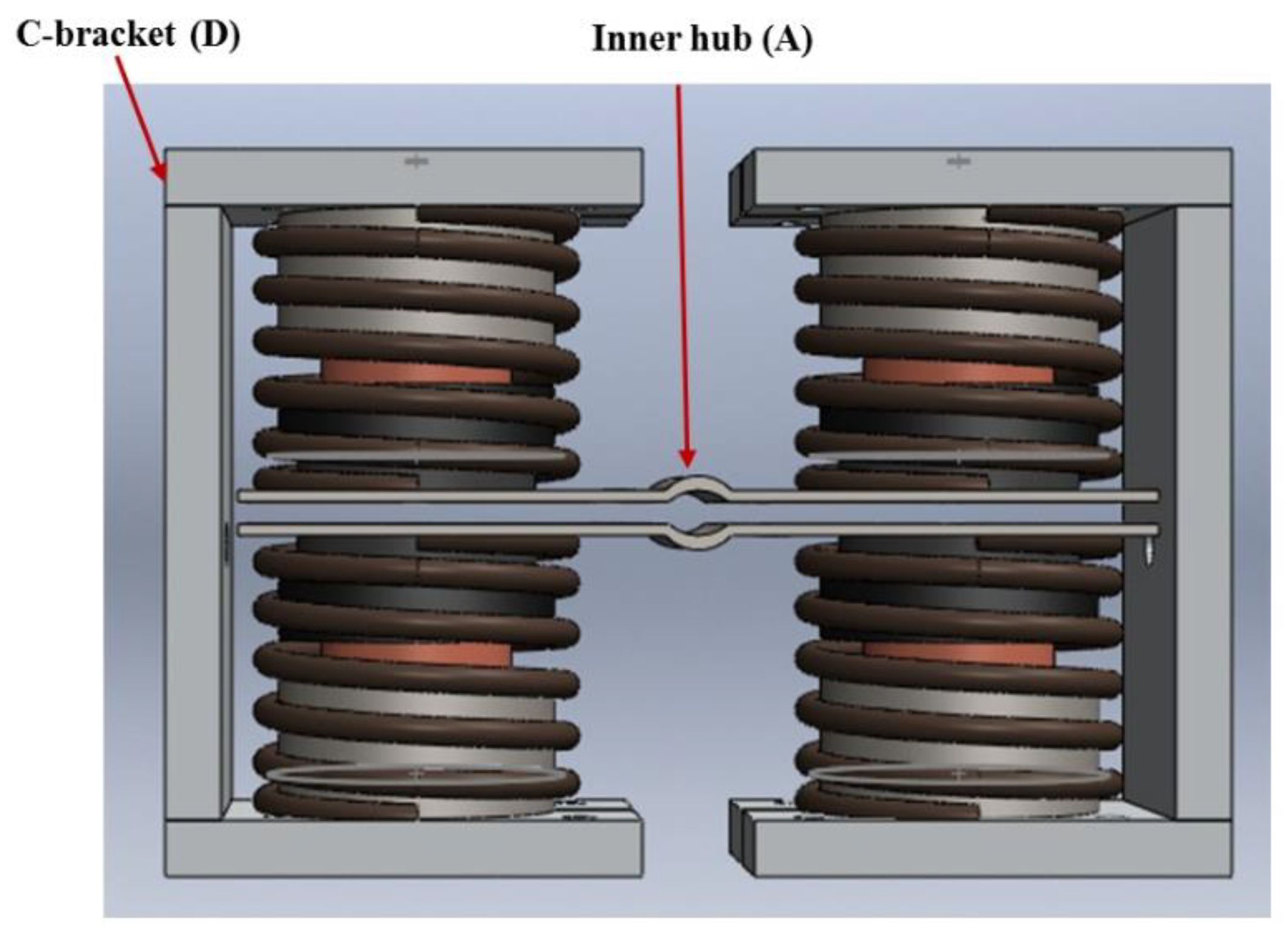
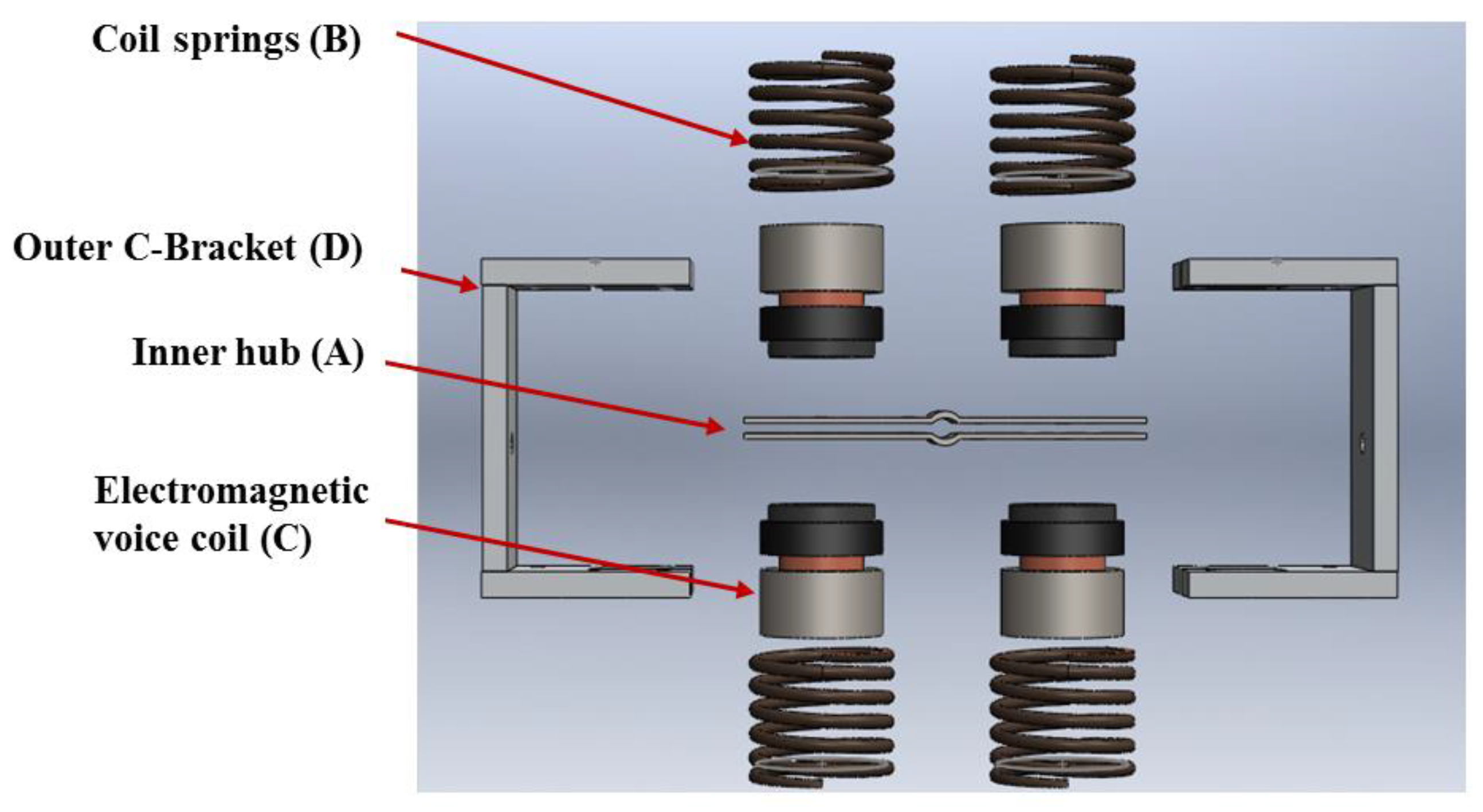
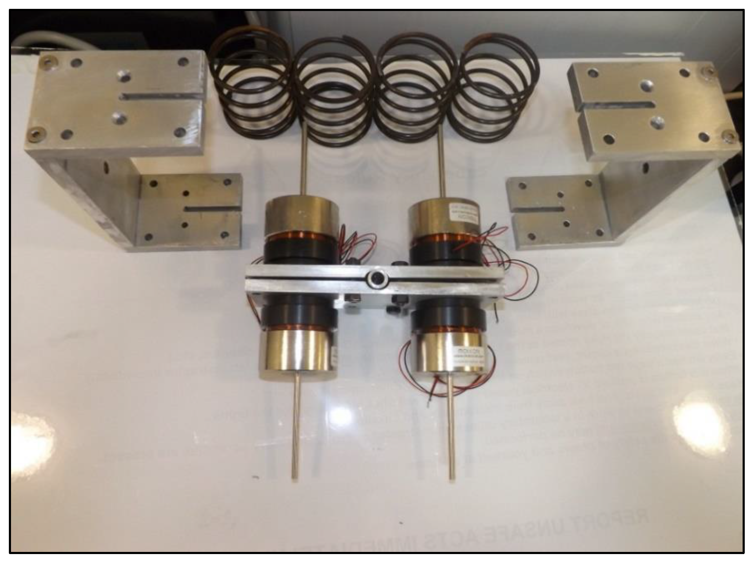
In a typical vibration absorber, the frequency at which structural response is minimized depends primarily on the lumped parameters (mass and stiffness). However, placing an effective stiffness of an electromagnetic actuator in parallel with the inherent structural stiffness of the conventional absorber would result in an equivalent stiffness that is a summation of both. In view of the above, four electromagnetic voice-coils were placed in parallel with four coil springs as per the schematic in Figure 1. The inner hub (A) consists of two rigid notched clamps which can be fastened on any shaft at any desired location. The effective mass of the absorber is represented by two C-bracket assemblies (D) as shown in Figure 2. Although torsional vibrations induce a rotational motion in the inner hub, this arrangement facilitates axial movements of the springs, the voice-coils, and the two masses.
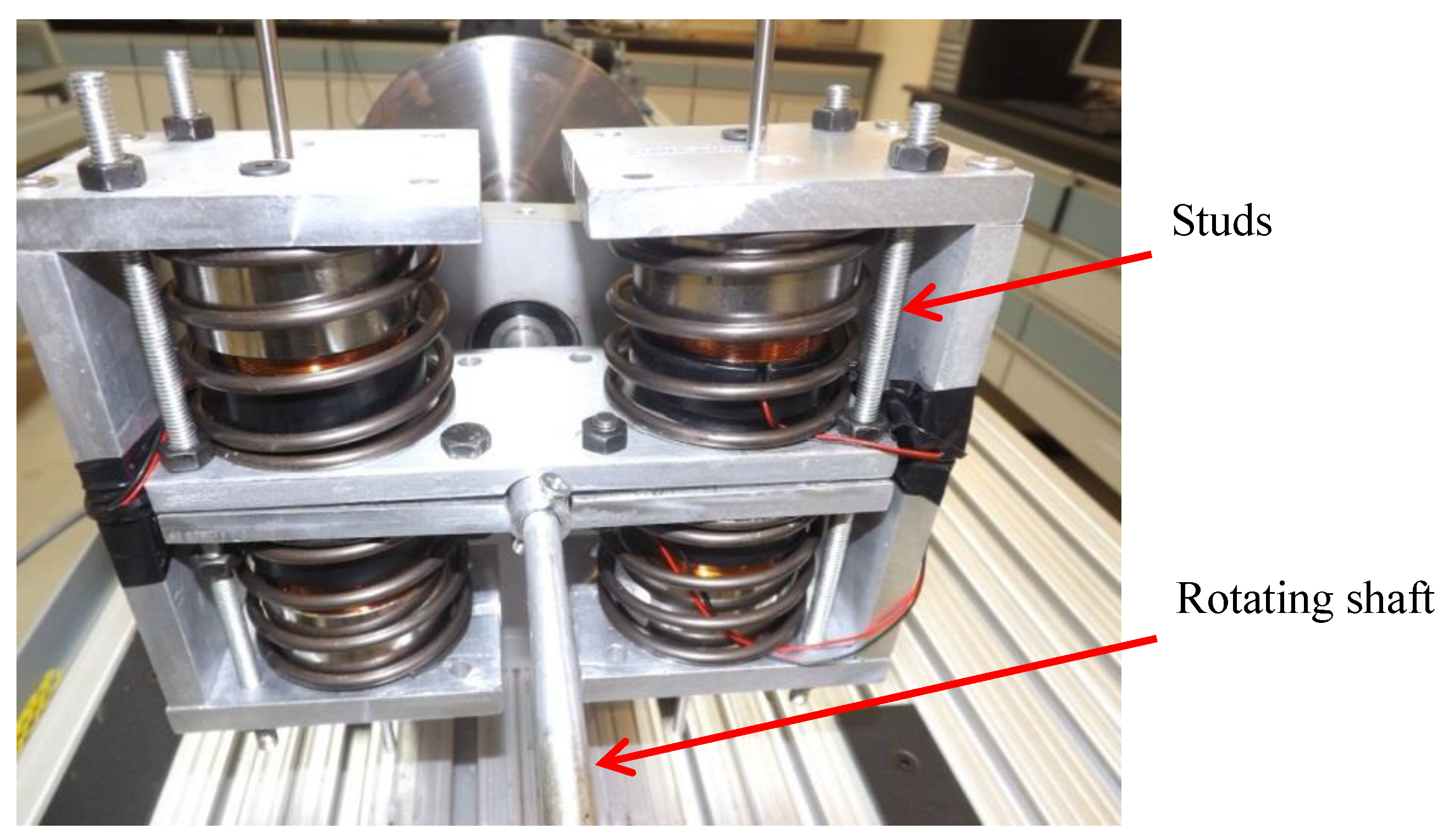
During normal operation, the ATTVA rotates with the shaft as part of the rotor system. Once torsional vibrations are induced in the shaft (resonance), the oscillations are transferred and absorbed by the inertia of C-brackets, which oscillate independently and in opposite directions (at the same frequency) to counteract the induced torque. This shall lead to significant suppression of torsional vibrations in the rotor system, since the C-brackets absorb torsional vibration energy.

2.2. Analytical Model of the ATTVA

The physical design was modeled mathematically and constitutive equations of motion were derived to simulate the dynamic behavior of the ATTVA system. Certain assumptions were made to facilitate the development of the model: the clamp is rigidly attached to the shaft of the primary system, the damping in the springs is assumed negligible, and the voice coil friction is assumed negligible due to self-aligning bushings. Resistance in the voice-coil is considered but the capacitor resistance is assumed zero, since this value is unknown. It shall be noted that the inertia of C-brackets, plus the weight of the magnets of the voice coil yields the effective mass (M) in the mathematical model.
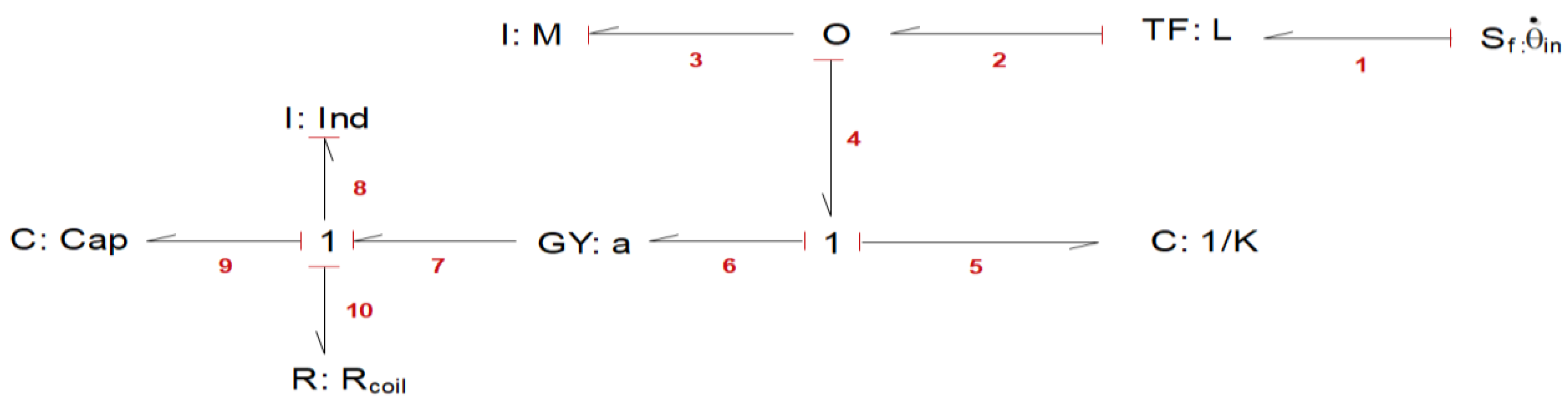
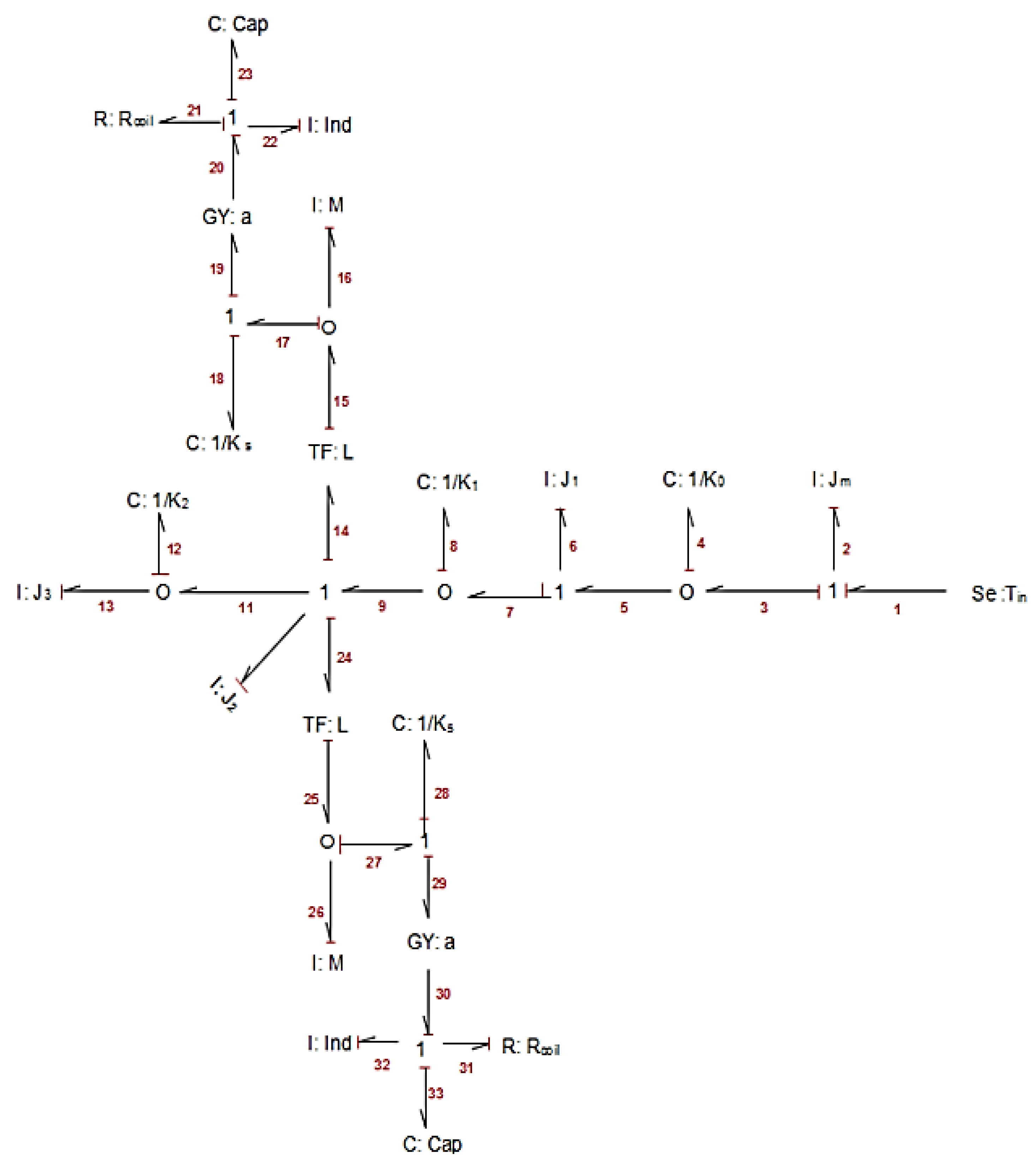
Since the model involves multiple energy domains (electro-mechanical), the bond graph modeling technique [29] was used to model the ATTVA (Figure 3) and derive constitutive equations of motion. Bond graph technique is a domain-independent graphical description of the dynamic behavior of physical systems. It is a powerful tool for modeling engineering systems, especially when different energy domains are involved (i.e., electrical, mechanical, acoustic, hydraulic, etc.).
Using the bond-graph model of Figure 3, the state-space equations are derived as follows:
State-space equations from Bond GraphEquivalent representation in standard form
p 3 ˙ = q 5 C 5 + α · p 8 I 8 x ¨ = k M Δ x s + α M · λ L (1)
q 5 ˙ = l · θ ˙ i n p 3 I 3 Δ x ˙ s = l θ i n ˙ x ˙ (2)
q 9 ˙ = p 8 I 8 i = λ L (3)
p 8 ˙ = α · ( l · θ ˙ i n p 3 I 3 ) q 9 C 9 R 10 · p 8 I 8 λ ˙ = α · ( l θ i n ˙ x ˙ ) Q C c a p R · λ L (4)
q” represents a generalized displacement variable; and “p” represents a momentum variable as described in Table 1. To simulate the model in MATLAB™, values of the voice coil parameters (force constant (α), resistance (Rcoil) and inductance (Ind)) were obtained from the available voice coil data sheet. Further, practical values were substituted for the physical parameters i.e., bracket mass (M), spring stiffness (K) and distance (L) as per Table 2 below.
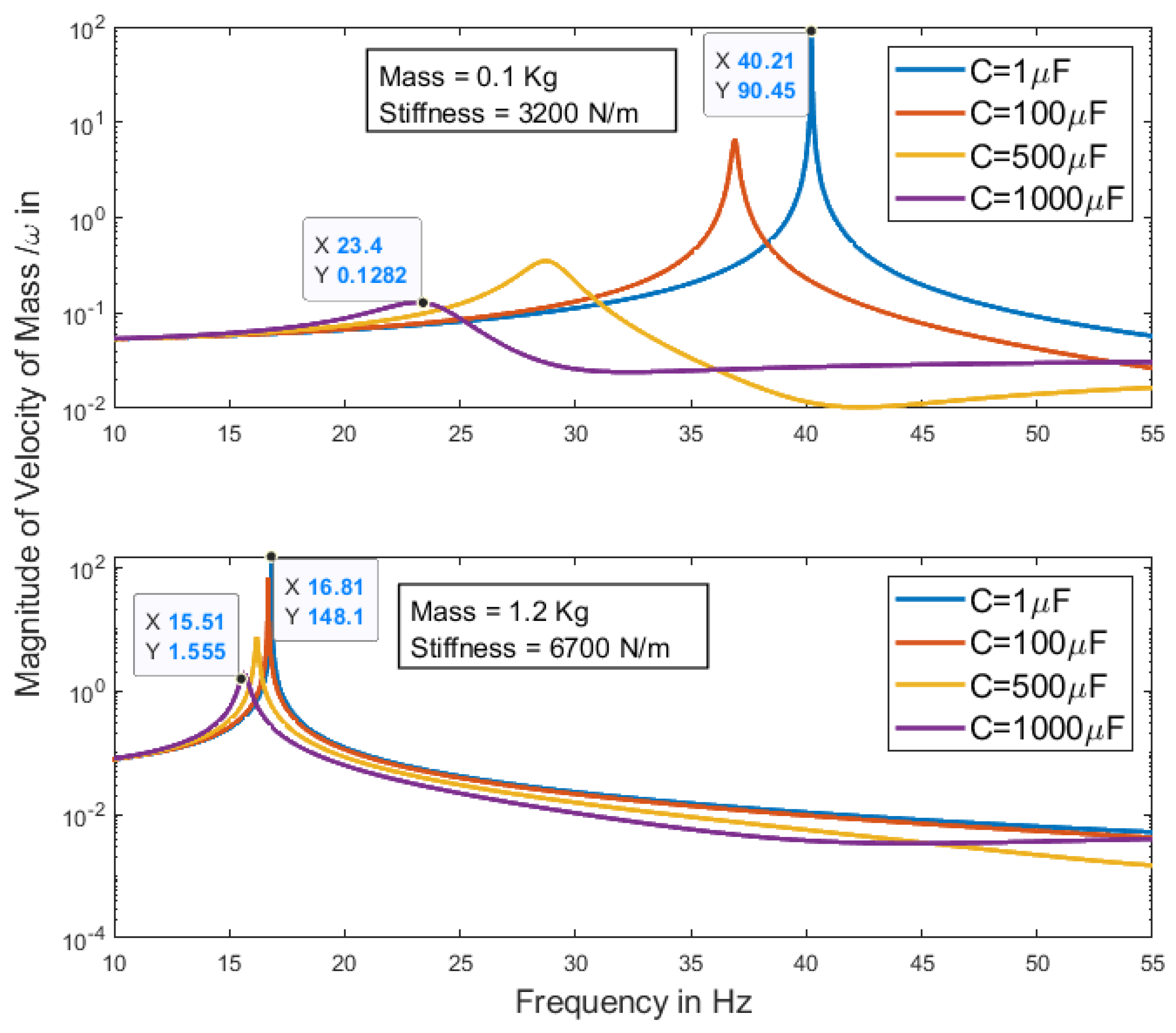
Constitutive state space Equations (1)–(4) were used to compute and plot the frequency response of the velocity of the ATTVA bracket mass (M) for various capacitance values. Results are shown in Figure 4 below. The simulation was run for two cases with different physical parameters to illustrate the impact of the lumped parameters on the tuning range of the absorber (Case 1: M = 0.1 kg, K = 3200 N/m) and (Case 2: M = 1.2 kg, K = 6700 N/m). In both cases, the only parameter which was varied throughout the simulation was the capacitance in the voice coil RLC circuit. This resembles an electrical shunt circuit in which the capacitance can be controlled over a wide range. Ultimately, the capacitance shall be varied from the open circuit configuration (relatively small capacitance) to the short circuit configuration (relatively high capacitance).
The plot in Figure 4 illustrates the change in tuning frequency (natural frequency) of the ATTVA with changing capacitance. For case 1, it is evident that the tuning frequency is 40.2 Hz when C = 1 μF (open circuit), and it shifts gradually to 36.9 Hz, 28.8 Hz and 23.2 Hz when the capacitance is increased from C = 1 μF to C = 100 μF, C = 500 μF, and to C = 1000 Μf, respectively. Therefore, the dynamic stiffness of the ATTVA and the natural frequency of the ATTVA are altered through discrete capacitance shunting. The apparent 40% drop in natural frequency demonstrates the ability to change the ATTVA natural frequency over a wide range of frequencies only by varying the capacitance.
For case 2, the mass and stiffness were tuned to yield a passive natural frequency of the system close to the primary natural frequency of the experimental set-up. The same values were used to build the prototype presented later in this paper. Similar to case 1, capacitance was varied in the model from C = 1 μF to C = 1000 μF. This results in a reduction of the natural frequency value from 16.8 Hz to 15.5 Hz (around 8%). This shows that the tunable range of the ATTVA is heavily affected by the lumped physical parameters of the absorber. The device can be tuned and the range can be optimized to suit different applications.

2.3. Control Algorithm

The electrical capacitive shunt circuit can be configured to change the apparent mass of the ATTVA. It was explained in [28] that when a capacitor is connected to a Gyrator (GY), see Figure 3, it plays the role of an inductor, and it is equivalent to a mass in a mechanical system. Therefore, when capacitance is varied in the coil circuit, the apparent mass of the ATTVA is changed; thus, its natural frequency. The variable capacitance can be varied from a very low capacitance which is equivalent to an open circuit, to a very high capacitance which is equivalent to a short circuit. Thus, there are limits on the range of apparent mass values that can be achieved through a variable capacitor.
To vary the capacitance, there are three MDOFs. Mechanically controlled variable capacitors can be used, but they are in picofarad range and they have to be tuned physically. Then there are digitally tunable capacitors but they are also in picofarad range and their tuning range is also very limited.
The third and best approach for the capacitive shunt circuit is the “capacitor ladder” circuit, with discrete capacitors wired in parallel which can be used to vary the capacitance through multiple switches arranged in the circuit. Manual switches cannot be used; so, to remotely control switches on and off, electrically operated switches, called relays, are recommended. But switches and relays can add resistance to the circuit which is not desired; so, great efforts should be taken to select low resistance relays. Electromechanical relays, in general, have lower resistance than solid state relays; thus they are the preferred choice.
This methodology was comprehensively described in [30] and briefly in [28]. The same approach can be implemented to control the apparent mass of the ATTVA device. Since this strategy was developed and tested in the previous research studies, it is not going to be described here. We refer our readers to reference [28]. In a rotary system with torsional vibration problems, incremental encoders will be used and attached to the main shaft. The encoders will measure the torsional vibration experienced by the shaft. LMS algorithm and encoders can be used to tune the capacitor ladder circuit and continue tuning until torsional vibrations are minimized.

2.4. Analytical Model of the Experimental Set-Up

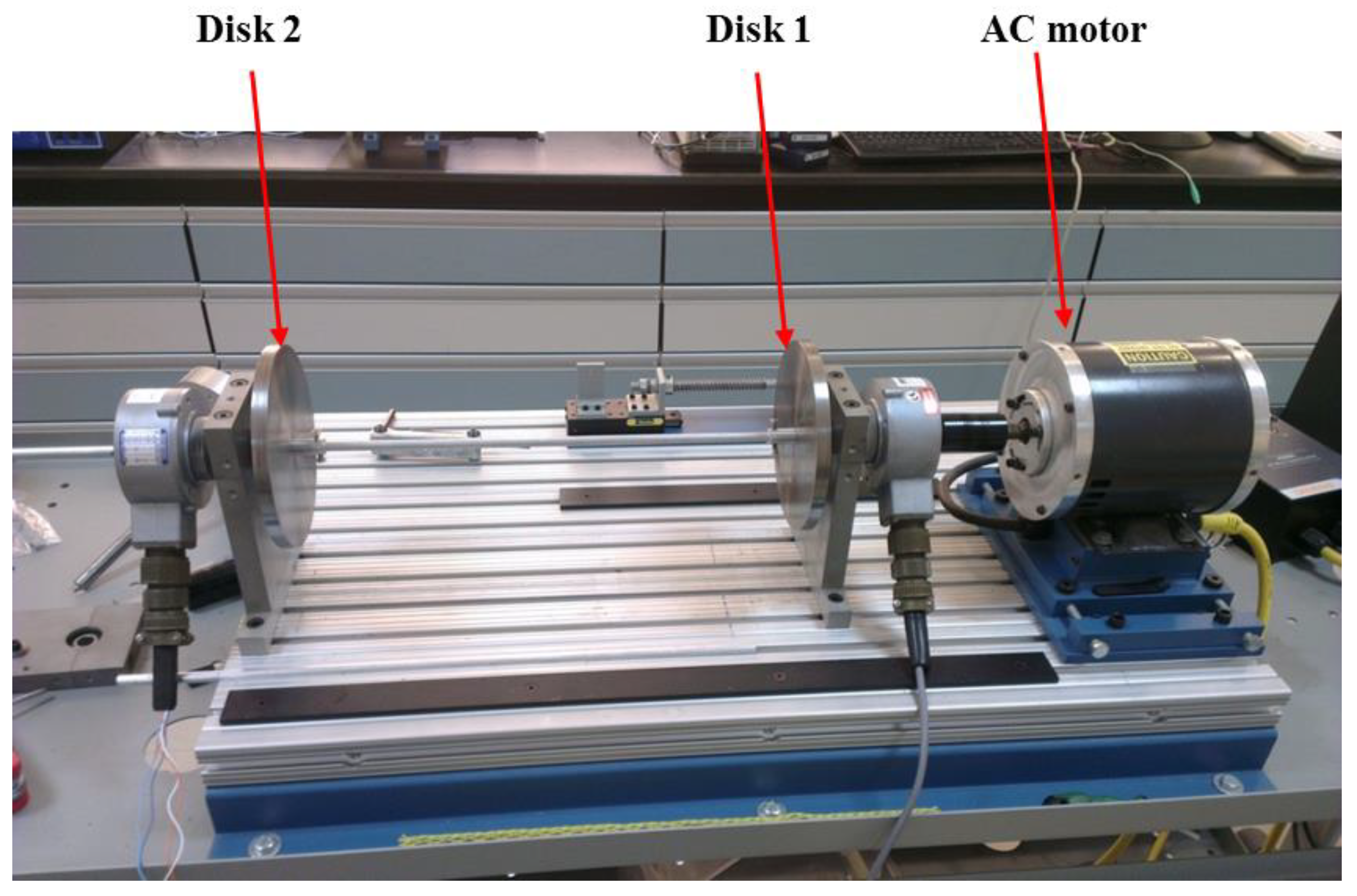
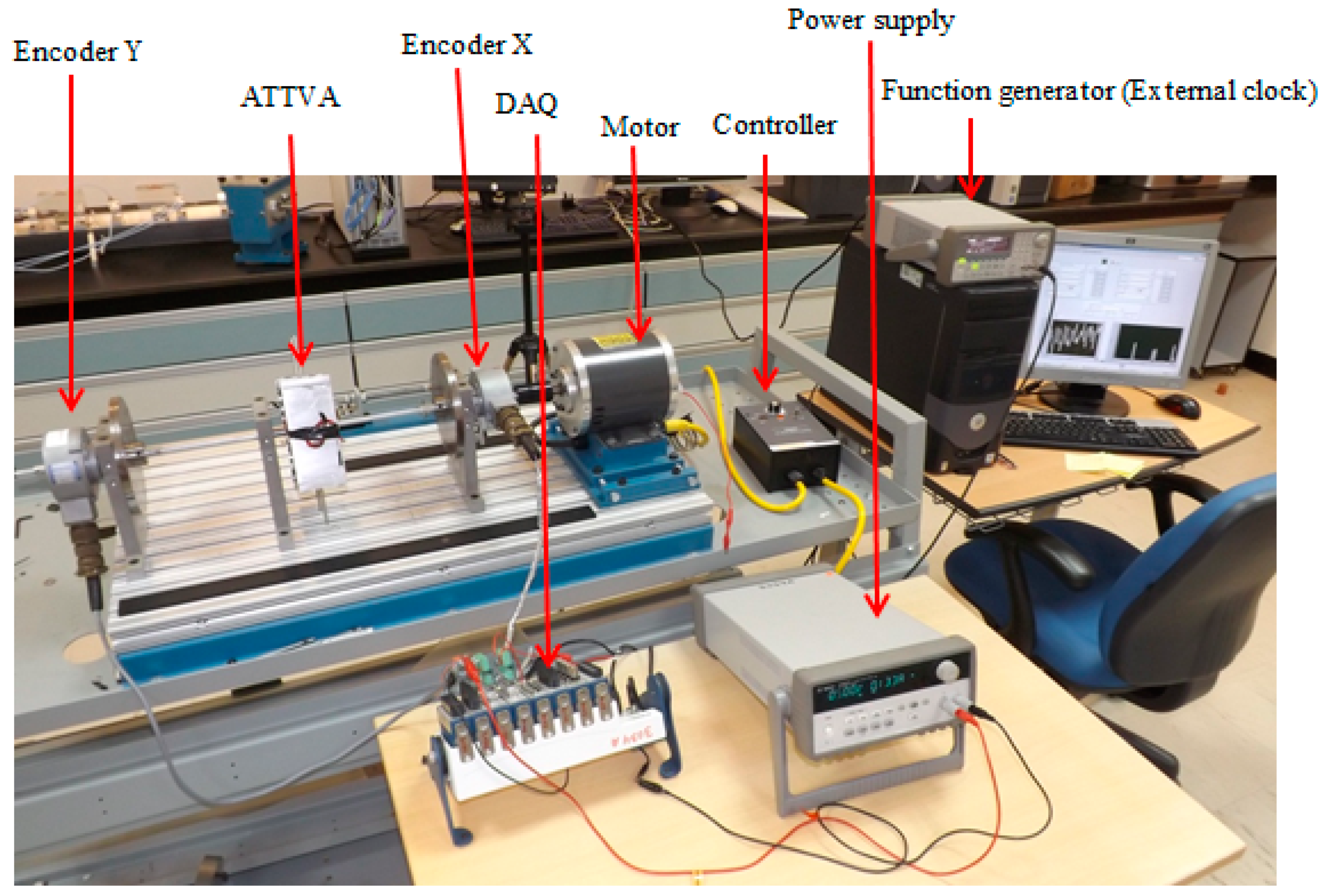
To validate the functionality of the device, an experimental test setup was assembled in the lab. In brief, the experimental test setup resembles a rotary system in a horizontal orientation. The prime mover is an AC induction motor (mimics the top drive), which drives two steel disks (Disk 1 mimics the rotary table, Disk 2 mimics the bottom hole assembly (BHA)) mounted on a(1/2)inch aluminum shaft (mimics the drill string), on which the ATTVA is mounted as shown in Figure 5.
The MDOF system of Figure 5 is modeled analytically and integrated into the previously derived ATTVA analytical model. Figure 6 shows the overall integrated bond graph model of the ATTVA, plus the experimental set-up system. It shall be noted that bonds 14 through 23 and 24 through 33, in the bond graph model, simply represent the bond graph model of the ATTVA, derived earlier.
State space equations, derived from the bond graph model of Figure 6, are as follows:
P 2 ˙ = τ i n ( t ) q 4 c 4
q 4 ˙ = P 2 I 2 P 6 I 6
P 6 ˙ = q 4 C 4 q 8 C 8
q 8 ˙ = P 6 I 6 P 10 I 10
P 10 ˙ = q 8 C 8 q 12 C 12 L · q 18 C 18 L α · P 22 I 22 L · q 28 C 28 L α · P 32 I 32
q 12 ˙ = P 10 I 10 P 13 I 13
P 13 ˙ = q 12 C 12
P 16 ˙ = q 18 C 18 + α · p 22 I 22
q 18 ˙ = L · P 10 I 10 P 16 I 16
P 22 ˙ = α L · P 10 I 10 α · P 16 I 16 R 21 · P 22 I 22 q 23 C 23
q 23 ˙ = P 22 I 22
P 26 ˙ = q 28 C 28 + α · P 32 I 32
q 28 ˙ = L · P 10 I 10 P 26 I 26
P 32 ˙ = α L · P 10 I 10 α · P 26 I 26 R 31 · P 32 I 32 q 33 C 33
q 33 ˙ = P 32 I 32
The states used in the model and corresponding parameters are defined in Table 3 and Table 4 below:
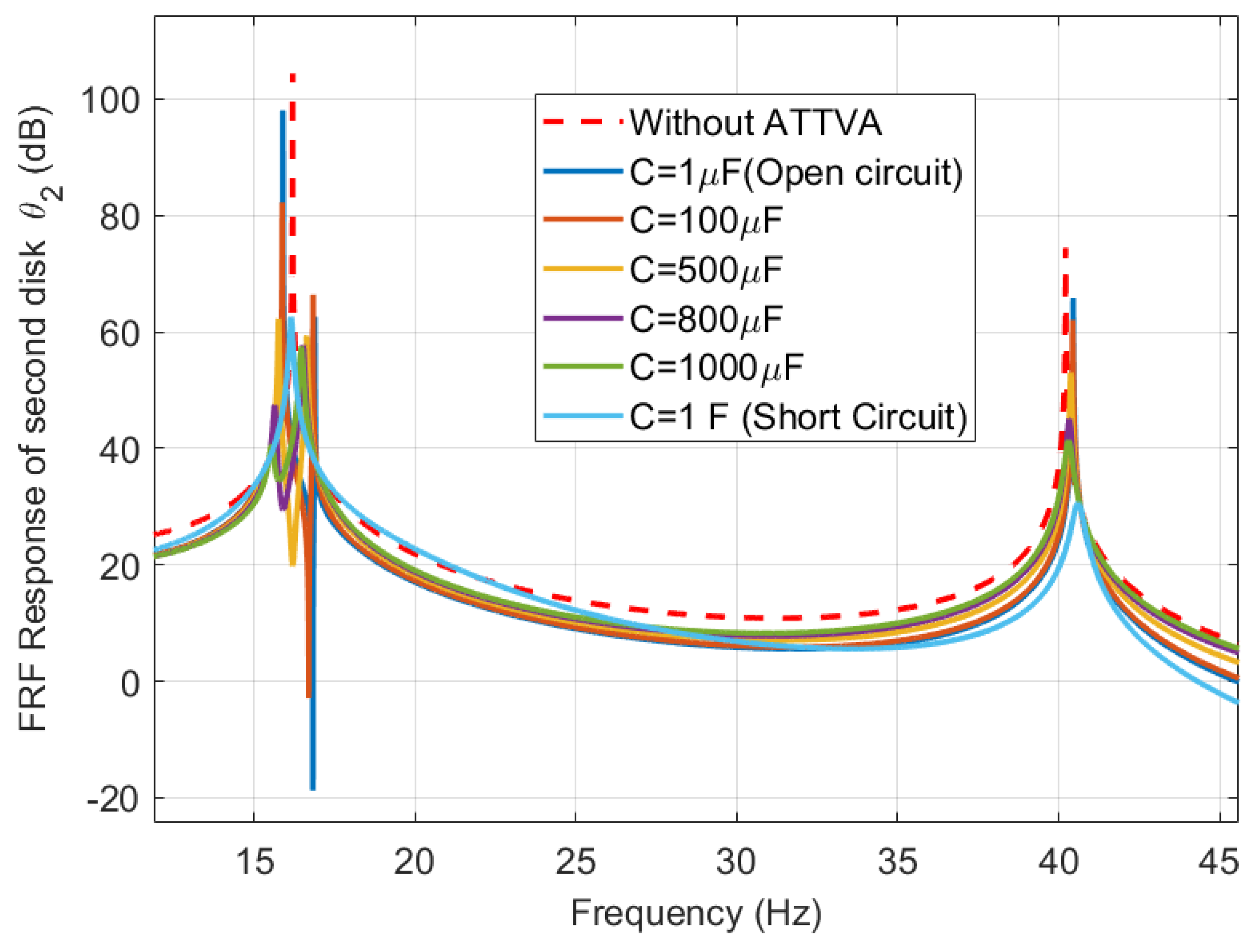
Equations of motion (5)–(19), are expressed in the state space form and simulated using MATLAB™ to obtain the frequency response of Disk 2, which is shown in Figure 7 and Figure 8. To obtain the original natural frequencies of the experimental set-up, the first run was carried out for the model without the ATTVA (red curve). Later, the ATTVA model was added to analyze the effect of adding the ATTVA inertia to the MDOF system.
The voice coil parameters were fixed to the ones used in the previous simulation in Section 2.2, whereas, other parameters of the ATTVA (spring stiffness and mass) were tuned to values used in Case 2 to yield a natural frequency marginally higher than the original natural frequency of the MDOF system. This allows tuning the frequency of the ATTVA to match the desired natural frequency of the MDOF system through increasing the capacitance value as discussed earlier (refer Figure 4).
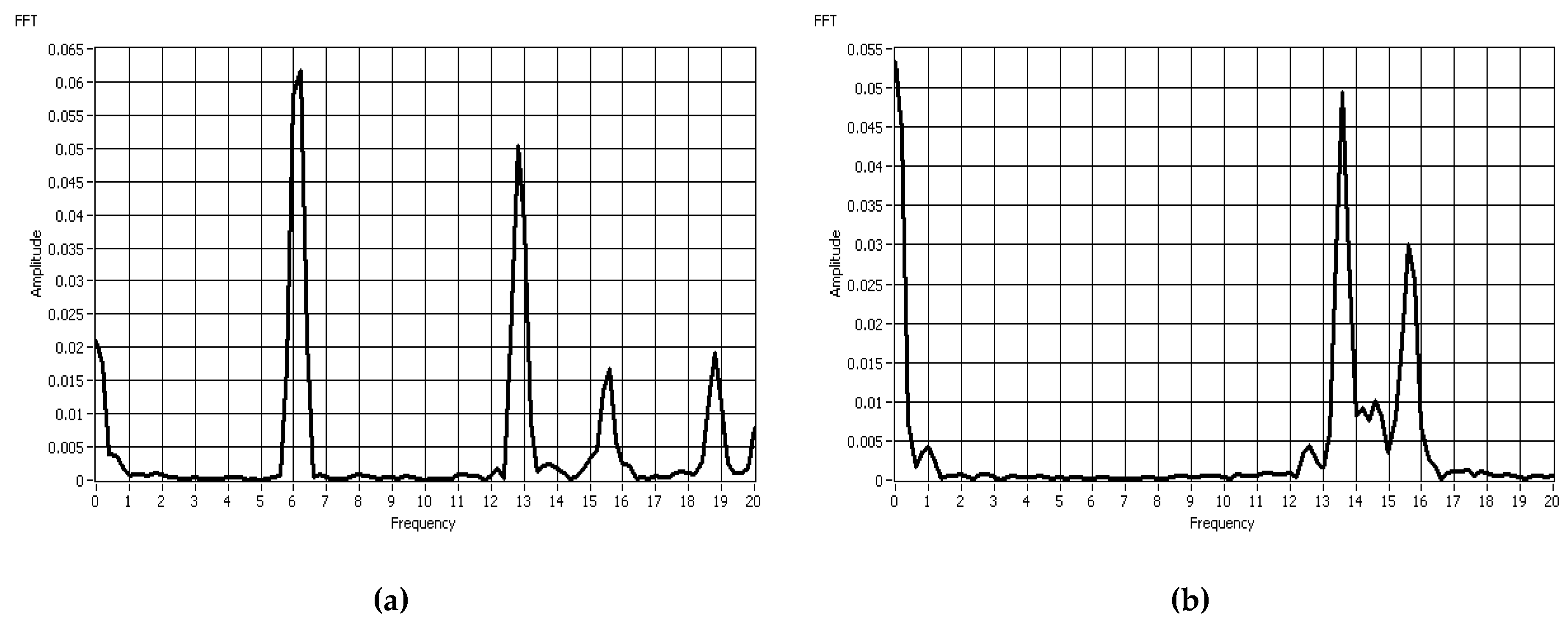
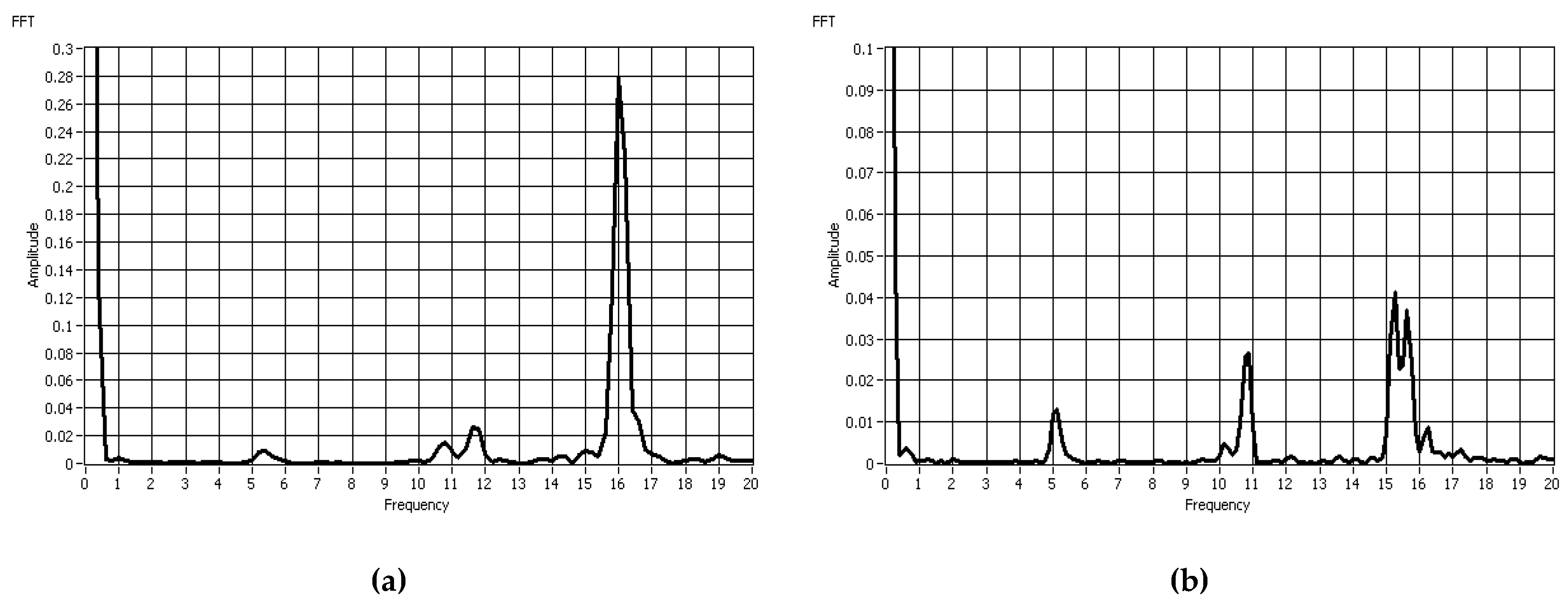
The data shows that the first natural frequency of the system without the ATTVA is 16.2 Hz (red dashed curve). Upon the addition of the ATTVA device with very small capacitance (open circuit configuration), the first peak has moved to 15.8 Hz, which represents the new natural frequency of the MDOF system (including the ATTVA). Further, another peak is observed at 16.9 Hz, which matches the passive tuned frequency of the ATTVA (blue curve). This peak is coupled with a notch (valley), which is a typical behavior of any tuned vibration absorber (TVA).
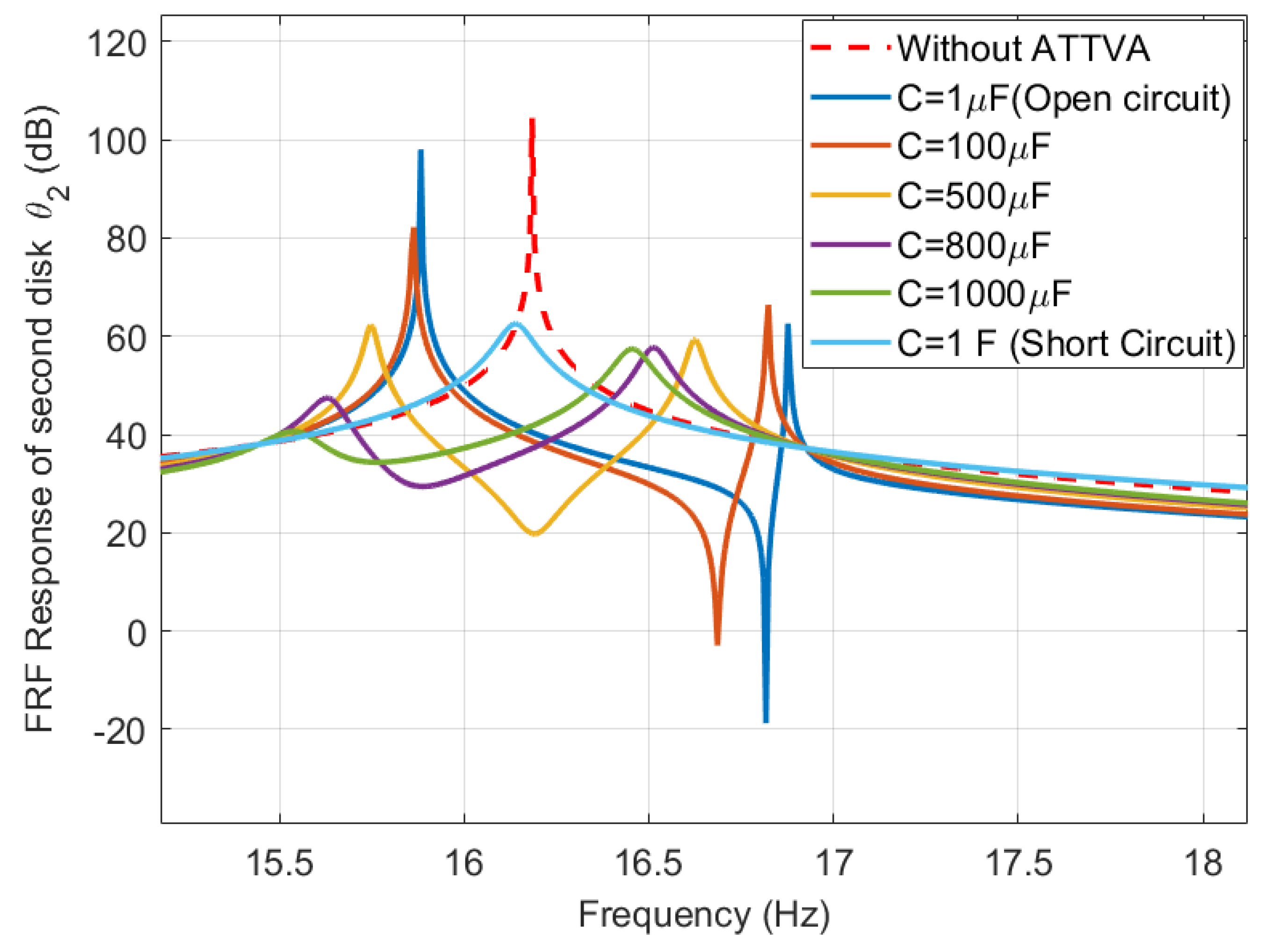
In the simulation, capacitance is increased to explore the effect of shunting the capacitance on shifting the notch frequency of the ATTVA over a range of frequencies. It is observed that upon increasing the capacitance, the notch frequency of the ATTVA shifts to the left (decreased), creating two peaks separated by a notch with noticeable reduction in magnitude (minima of the red, yellow, and purple curves).
Since the frequency of interest is 15.8 Hz, the capacitance is increased gradually until the notch frequency moves to 15.8 Hz. When the capacitance is C = 800 μF, the response shows a valley (notch) with maximum reduction in magnitude at 15.8 Hz. Furthermore, simulation results show that the notch depth decreases for higher capacitances indicating higher damping, which limits the performance of the ATTVA. The notch diminishes when the capacitance is increased to a very high value (closed circuit configuration). This implies that the tunable range of the ATTVA is bounded by the short-circuit (or infinite capacitance) and the open-circuit (or zero capacitance) shunted circuits.
In the application described here, the absorber is efficient in suppressing the response at frequencies closer to the passive natural frequency of the ATTVA. Therefore, to achieve superior performance of the ATTVA, the passive natural frequency of the ATTVA shall be marginally higher than the desired natural frequency of the MDOF system. This discussion illustrates the functionality of the ATTVA in mitigating torsional vibrations in an MDOF system over a reasonable range of frequencies (in this case from 16.9 Hz to 15.8 Hz). Though the frequency bandwidth seems narrow, this range is reasonable in low frequency applications where the rotary is system is driven at low RPM, such as the drill string (120–150 RPM) [13].

3. Experimentation and Results

3.1. ATTVA Prototype Construction

To validate the model of the ATTVA, a prototype was built (see Figure 9 and Figure 10) and tested on a rotary test rig shown in Figure 5. C-brackets and the inner hub were fabricated to match required dimensions that were obtained using the mathematical model. The clamps were designed with longitudinal notches to be fastened on the rotating shaft. Studs with nuts were used to lock the C-bracket with the clamp, and prevent relative movements of the springs/voice coils when the ATTVA is in inactive mode.
Four identical helical coil springs were custom designed and manufactured to match the spring stiffness rate and the relative displacement as predicted by the mathematical model. The electro-magnetic voice coils were selected based on their force sensitivity, low electrical resistance, dimensions and weight. The available voice coil in the market with the minimum resistance in this size range was “MotiCont GVCM-051-025-01”, with a force sensitivity of 6.9 N/Amp, and coil resistance and inductance of 1.7 Ω and 0.6 mH, respectively. This linear voice coil has an internal low friction bearing to keep the coil concentric with the field assembly.

3.2. Instrumentation and Measurement Techniques

Figure 11 shows the experimental test setup with the ATTVA and two high resolution (10,000 PPR) incremental encoders (BEI Model # HS35). Both encoders were connected to a 5 V power supply, and their signals were transferred to the data acquisition module (DAQ), which manipulates the data and sends it to the PC. The first encoder was mounted next to the motor to measure the input angle, whereas the second encoder was placed next to the second disk to measure the torsional vibration in that disk. Since the output of encoders was in degrees, the difference between the angle readings from encoders X and Y indicates the torsional vibration induced in the system, when the steady state condition was achieved. The motor was equipped with a controller to control the rotational speed ranging from 0 to 3450 RPM.
Since the experiment required collecting data from both encoders and calculating the difference in angles instantly, a shared external sample clock was used to ensure synchronized and simultaneous measurements from both encoders. The pulse rate generated by incremental encoders is a function of the rotational speed and the pulses per revolution (PPR) of the encoder. It is expressed according to the formula: F p u l s e =   P P R R P M 360   .
Following the Nyquist Sampling Theorem, the sampling frequency was set at 100 kHz based on the accuracy of the encoders (10,000 PPR) and the maximum speed of rotation (1400 RPM). The Fast Fourier Transform (FFT) was used to analyze the frequency content of discrete signals.

3.3. Experimental Results and Discussion

Three main experiments were carried out to examine the functionality of the ATTVA and compare results to the simulation from the mathematical model.

3.3.1. Experiment I–without ATTVA

The objective of the first experiment was to validate the natural frequency of the rotary system without the ATTVA experimentally. The experimental setup was excited by running the motor at different speeds of rotation. The speed of the motor was varied manually with a controller knob, since it was not equipped with a feedback loop controller. From the time domain data, the difference in the angle between the two encoders (Angle 1 from encoder X, and Angle 2 from encoder Y) was recorded at each rotational speed, and the frequency spectrum was acquired using the FFT as shown in Figure 12.
Figure 12 shows distinct peaks at different frequencies corresponding to each running speed as per Table 5 below:
The analysis of these peaks revealed that the first peak always shows up at the running frequency, whereas the subsequent peaks are simply the harmonic multiples of the running frequency. However, a specific peak was consistent in all the spectrums around 16 Hz, regardless of the running speed. This implies that the first natural frequency of the experimental test setup is in this range 16–16.5 Hz, which matches well with the derived natural frequency from the analytical model and simulation.

3.3.2. Experiment II–with ATTVA Mounted in Locked Configuration

The second set of experiments was carried out to investigate the effect of adding the ATTVA mass (inertia) on the dynamics and natural frequencies of the experimental test setup. This was achieved by locking the springs and voice coils and preventing their motion using studs and locking nuts as shown in Figure 13 to make the ATTVA act as a rigid body (inertia).
The same approach was used in experiment II, in which the experimental test setup was excited at different rotational speeds and the encoder time responses were processed with FFT. Since experiment I showed that the natural frequency of the original system was around 16 Hz, the speeds of the motor were chosen so that that none of the multiples of the running speeds lay between 14 Hz and 17 Hz in order to examine the shift in the natural frequency of the system after the addition of the ATTVA inertia.
When the system was driven at 360 RPM (6 Hz), the peaks were observed at the running speed (6 Hz), at the harmonic multiples (~12 Hz and ~18 Hz), and at 15.5 Hz as shown in Figure 14a. In Figure 14b, a similar peak showed up at 15.5 Hz, in addition to the peak at the running frequency (13.5 Hz). Since 15.5 Hz was not a harmonic of any of the rotational speeds in both runs, this implies that 15.5 Hz is the natural frequency of the new system (with the ATTVA attached in the locked configuration). Comparing this outcome with the previous experiment, we observe that the natural frequency of the system has decreased from about 16 Hz to approximately 15.5 Hz due to the addition of ATTVA inertia. This is in line with the simulation of the mathematical model described in Section 2.4. The new frequency is close to the tuned frequency of the ATTVA, and it shall be suppressed by activating the ATTVA.

3.3.3. Experiment III–Activated ATTVA

In the last experiment, the ATTVA was unlocked to observe the impact of the “active” ATTVA on the amplitude of the vibration at the desired natural frequency. The studs and nuts were removed from the ATTVA, and the springs/voice coils were set free to move axially (Figure 15). Utilizing the same concept of capacitance shunting that was proven experimentally in the translational model in [27], the ATTVA was tested in two configurations:
  • Open-circuit configuration: The ends of the voice coil wires were left open during the experiment.
  • Short-circuit configuration: The ends of the voice coil wires were connected to each other.
These two configurations represent the extremities of the minimum and the maximum capacitances that can be added to the voice coil circuit.
In both experiments, the system was excited around 5 Hz (300 RPM). In the open circuit experiment (Figure 16a), a distinct peak with a high magnitude of 0.28 degrees is observed at the natural frequency of 16 Hz, along with another peak at the running frequency (~5 Hz) with a magnitude of 0.01 degrees, and a peak at the first multiple (~11 Hz) with magnitude of 0.03 degrees. The effect of the ATTVA was perceptible when the voice-coil electric circuit was closed (Figure 16b), in which two new peaks appear around the 16 Hz frequency with a clear reduction (a notch showing as a valley) attained at the 16 Hz. Noticeably, the peak which was at 16 Hz with 0.28-degree magnitude was attenuated by more than 10 times to less than 0.03 degrees, whereas the magnitude of other peaks remained the same. Additionally, the peaks shifted slightly to the left when the circuit of the coils was shortened, which proves the functionality of the ATTVA as predicted in the analytical model.

4. Conclusions

The purpose of this research was to develop a practical adaptive device for suppressing torsional vibrations of any rotating machinery with time varying excitation frequency or varying natural frequencies. The developed Adaptive Torsional Tuned Vibrational Absorber (ATTVA) employs an RLC circuit with an electromagnetic voice coil and capacitances. The effective stiffness of the ATTVA and its natural frequency can be tuned over a range of frequencies through shunting the capacitance. Experimental results agree well with simulations of analytical models. Noticeable reduction in torsional vibration amplitude was observed at the first natural frequency of the experimental test setup/ATTVA system.
It is possible to adapt the natural frequency of the device presented in this work to a specific desired value based on the changes in the main system. Further, the absorber parameters can be adjusted to suit any rotating machinery application (drill string, submersible pumps, etc.) at any frequency range. The proposed ATTVA, appears large for the experimental test set-up, but the authors believe that the size of the device can be made smaller and if designed properly, it can be very useful to control torsional vibrations in any rotating equipment.

Author Contributions

T.A.S. developed the analytical models. N.V. verified the models and provided the experimental methodology. T.A.S. manufactured the ATTVA prototype and carried out the experiments. T.A.S, N.V. and O.S. analyzed the results. N.V. and O.S. supervised the project and provided their technical expertise throughout the experiments. T.A.S. took a major role in writing the paper.

Funding

This research received no external funding.

Acknowledgments

The authors are grateful to Hamad Karki and Arman Molki for their continuous support and contribution throughout the project. The authors would also like to acknowledge the support provided for this research by the Petroleum Institute and the Khalifa University of Science and Technology.

Conflicts of Interest

The authors declare no conflict of interest.

References

  1. Aarsnes, U.; van de Wouw, N. Axial and torsional self-excited vibrations of a distributed drill-string. J. Sound Vib. 2019, 444, 127–151. [Google Scholar] [CrossRef]
  2. Khulief, Y.; Al-Sulaiman, F.; Bashmal, S. Vibration analysis of drillstrings with self-excited stick–slip oscillations. J. Sound Vib. 2007, 299, 540–558. [Google Scholar] [CrossRef]
  3. Challamel, N. Rock destruction effect on the stability of a drilling structure. J. Sound Vib. 2000, 233, 235–254. [Google Scholar] [CrossRef]
  4. Kabziński, J. Adaptive Control of Drillstring Torsional Oscillations. IFAC-PapersOnLine 2017, 50, 13360–13365. [Google Scholar] [CrossRef]
  5. Engineering Vibration, D.J. Inman, 4th ed.; Pearson Education Limited: England, UK, 2014; pp. 467–475. [Google Scholar]
  6. Alabdullatif, Z.A. Analysis of Downhole Drilling Vibrations: Case Studies of Manifa and Karan Fields in Saudi Arabia; University of Texas: Austin, TX, USA, 2011. [Google Scholar]
  7. Macpherson, J.D.; Mason, J.S.; Kingman, J.E.E. Surface Measurement and Analysis of Drillstring Vibrations While Drilling. In Proceedings of the SPE/IADC Drilling Conference, Amsterdam, The Netherlands, 22–25 February 1993. [Google Scholar]
  8. Chevallier, A. A Probabilistic Approach to the Frequency Domain Analysis of Drill-String Lateral Vibrations. Master’s Thesis, Rice University, Houston, TX, USA, 1998. [Google Scholar]
  9. Jansen, J.D.; van den Steen, L. Active damping of self-excited torsional vibrations in oil well drillstrings. J. Sound Vib. 1995, 179, 647–668. [Google Scholar] [CrossRef]
  10. Craig, A.D.; Hanley, C.; McFarland, B.; Shearer, D.R.; King, P.D. A Proven Approach to Mitigating Drilling Vibration Problems in offshore Western Australia. In Proceedings of the International Petroleum Technology Conference, Doha, Qatar, 7–9 December 2009. [Google Scholar]
  11. Halsey, G.W.; Kyllingstad, A.; Aarrestad, T.V.; Lysne, D. Drillstring Torsional Vibrations: Comparison between Theory and Experiment on a Full-Scale Research Drilling Rig. In Proceedings of the SPE Annual Technical Conference and Exhibition, New Orleans, LA, USA, 5–8 October 1986. [Google Scholar]
  12. Peltier, B.P.; Cooper, G.A.; Curry, D.A. Use of Torque Analysis to Determine Tricone Bit Bearing Failure. In Proceedings of the SPE Annual Technical Conference and Exhibition, Dallas, TX, USA, 27–30 September 1987. [Google Scholar]
  13. Besaisow, A.A.; Payne, M.L. A Study of Excitation Mechanisms and Resonances Inducing Bottomhole-Assembly Vibrations. SPE Drill. Eng. 1988, 3, 93–101. [Google Scholar] [CrossRef]
  14. Burgess, T.M.; McDaniel, G.L.; Das, P.K. Improving BHA Tool Reliability with Drillstring Vibration Models: Field Experience and Limitations. In Proceedings of the SPE/IADC Drilling Conference, New Orleans, LA, USA, 15–18 March 1987. [Google Scholar]
  15. Jogi, P.N.; Neubert, M.; Macpherson, J.D. Field Verification of Model-Derived Natural Frequencies of a Drill String. J. Energy Resour. Technol. 2002, 124, 154–162. [Google Scholar] [CrossRef]
  16. Kyllingstad, A.; Halsey, G.W. A Study of Slip/Stick Motion of the Bit. SPE Drill. Eng. 1988, 3, 369–373. [Google Scholar] [CrossRef]
  17. Cobern, M.E.; Perry, C.A.; Burgess, D.E.; Barbely, J.R.; Wassell, M. Drilling Tests of an Active Vibration Damper. In Proceedings of the SPE/IADC Drilling Conference, Amsterdam, The Netherlands, 20–22 February 2007. [Google Scholar]
  18. Wilson, W.K. Practical Solution of Torsional Vibration Problems; Chapman Hall: London, UK, 1968. [Google Scholar]
  19. Sun, Y.; Tomas, M. Control of torsional rotor vibrations using an electrorheological fluid dynamic absorber. J. Vib. Control 2011, 17, 1253–1264. [Google Scholar] [CrossRef]
  20. Hoang, N.; Zhang, N.; Du, H. A dynamic absorber with a soft magnetorheological elastomer for powertrain vibration suppression. Smart Mater. Struct. 2009, 18, 074009. [Google Scholar] [CrossRef] [Green Version]
  21. Den Hartog, J.P.; Ormondroyd, J. Torsional vibration dampers. Trans. Am. Soc. Mech. Eng. 1930, 52, 133. [Google Scholar]
  22. Meng, X.J.; Li, J.W. Idling Natural Characteristic Analysis of the Torsion Absorber with Dual Mass Flywheel. Appl. Mech. Mater. 2011, 80–81, 860. [Google Scholar] [CrossRef]
  23. Cai, Q.C.; Park, J.-H.; Lee, C.-H.; Park, J.-L.; Yoon, D.-Y. A semi-active smart tuned mass damper for drive shaft. In Proceedings of the Korea Society for Noise and Vibration Engineering (KSNVE), 2011 Annual Fall Conference, Interburgo Hotel, Daegu, South Korea, 27–28 October 2011; pp. 349–354. [Google Scholar]
  24. Mizuno, T.; Araki, K. Control system design of a dynamic vibration absorber with an electromagnetic servomechanism. Mech. Syst. Signal Process. 1993, 7, 293–306. [Google Scholar] [CrossRef]
  25. Al Matsuzaki, Y. Electromagnetic forces for a new vibration control system: Experimental verification. Smart Mater. Struct. 2000, 9, 127. [Google Scholar] [CrossRef]
  26. Tentor, L.B. Characterization of an Electromagnetic Tuned Vibration Absorber. Ph.D. Thesis, Virginia Polytechnic Institute and State University, Blacksburg, VA, USA, August 2001. [Google Scholar]
  27. Seer, T.A.; Vahdati, N.; Karki, H.; Shiryayev, O. Adaptive electromagnetic torsional tuned vibration absorber and its applications in rotating equipment. In Proceedings of the 14th International Mechanical Engineering Congress and Exposition (IMECE2012), Houston, TX, USA, 9–15 November 2012. [Google Scholar]
  28. Vahdati, N.; Seer, T.A. An Adaptive Electromagnetic Torsional Vibration Absorber. In Proceedings of the 20th International Congress on Sound and Vibration (ICSV20), Bangkok, Thailand, 7–11 July 2013. [Google Scholar]
  29. Karnopp, D.C.; Margolis, D.L.; Rosenberg, R.C. System Dynamics: Modeling, Simulation, and Control of Mechatronic Systems, 5th ed.; John Wiley and Sons: Hoboken, NJ, USA, 2012. [Google Scholar]
  30. Heidari, M.S. Development of Variable Multiple-Notch and Multi-Function Fluid Mounts. Ph.D. Thesis, Nanyang Technological University, Singapore, 2010; pp. 132–137. [Google Scholar]
Figure 1. Conceptual design II of the adaptive torsional tuned vibration absorber (ATTVA) (front view).
Vibration 02 00008 g001
Figure 2. Conceptual design II of the ATTVA (exploded view).
Vibration 02 00008 g002
Figure 3. Bond graph model of the ATTVA conceptual design.
Vibration 02 00008 g003
Figure 4. Simulation of the frequency response of the ATTVA (Case 1 and Case 2) for various capacitances.
Vibration 02 00008 g004
Figure 5. Schematic representation of the experimental Multi Degree of Freedom (MDOF) system.
Vibration 02 00008 g005
Figure 6. Bond graph model of the experimental test rig plus the integrated ATTVA.
Vibration 02 00008 g006
Figure 7. FRF for disk 2 with the ATTVA (disk 2 angle/input torque).
Vibration 02 00008 g007
Figure 8. FRF for disk 2 with ATTVA (zoomed-in on frequency range from 15 Hz to 18 Hz).
Vibration 02 00008 g008
Figure 9. ATTVA Prototype manufactured and assembled for this project as per the physical model and parameters (Section 2.1).
Vibration 02 00008 g009
Figure 10. An exploded view of the ATTVA, showing all components.
Vibration 02 00008 g010
Figure 11. Experimental test rig setup in the laboratory.
Vibration 02 00008 g011
Figure 12. (a) Frequency spectrum of angle difference amplitude without ATTVA at 120 RPM (2Hz) (b) at 480 RPM (8Hz) (c) at 720 RPM (12Hz) (d) at 960 RPM (16Hz).
Vibration 02 00008 g012
Figure 13. The ATTVA mounted on the rotating shaft in the locked position.
Vibration 02 00008 g013
Figure 14. (a) Frequency spectrum of the angle difference amplitude with ATTVA locked at 360 RPM (6 Hz) (b) at 810 RPM (13.5 Hz).
Vibration 02 00008 g014
Figure 15. Image of the experimental setup with the ATTVA mounted in the activated configuration.
Vibration 02 00008 g015
Figure 16. (a) The Fast Fourier Transform (FFT) of the angle difference for open-circuit configuration at 5 Hz (b) The FFT of the angle difference for closed-circuit configuration at 5 Hz.
Vibration 02 00008 g016
Table 1. States used in the bond graph model.
StatesDefinitionUnits
p3Momentum of the C-bracket ( M · x ˙ )kg·m/s
q5Motion across the coil springsmeters
p8Flux linkage (λ): Time integral of the induced voltage in voice coilWb (Weber)
q9Charge across the capacitance that was added to the voice coilC
Table 2. Baseline parameters.
ParametersDefinitionUnitsValues
k (C5 = 1/k)stiffness of two coil springsN/mCase 1: 3200
Case 2: 6700
I8 = LInductance of the voice coilmH0.6
I3 = MMass of one C-bracket plus voice coil magnetskg0.1
R10Total electrical resistance of the voice coilOhms1.2
αForce sensitivity of the voice coilN/amps6.9
C9Variable capacitance added to the voice coilFarad1, 100, 500, 1000
lPerpendicular distance between the center of the hub and center of spring/voice coilmeters0.05
Table 3. States used in the comprehensive bond graph model.
StatesDefinitionUnits
P2the momentum of the motor inertiakg·m2/s
q4relative angular displacement between the motor and disk 1rad
P6Momentum of disk 1kg·m2/s
q8Relative angular displacement between disk 1 and ATTVArad
P10Momentum of ATTVA hubkg·m2/s
q12Relative angular displacement between disk 2 and ATTVArad
P13Momentum of disk 2 kg·m2/s
P16, P26Momentum of each C-bracketskg·m/s
q18, q28relative displacement of the coil springm
P22, P32flux linkage variable (λ), equal to time integral of the induced voltage in the voice coilWb
q23, q33Induced electrical charge in the voice coil-RLC circuitQ
Table 4. Parameters used in the comprehensive bond graph model.
ParametersDefinitionUnits
τinInput torque from the motorN·m
C41/K0 where K0 is the stiffness of shaft segment between motor and disk 11/N·m2
I2Mass moment of inertia of the motorkg·m2
I6:Mass moment of inertia of disk 1kg·m2
C81/K1 where K1 is the stiffness of shaft segment between disk 1 and ATTVA1/N·m2
I10Mass moment of inertia of ATTVA hubkg·m2
C121/K2 where K2 is the stiffness of shaft segment between disk 2 and ATTVA1/N·m2
C18, C281/Ks where Ks is the stiffness of the coil springm/N
I22, I32Inductance of the voice coilsmH
I13Mass moment of inertia of disk 2kg·m2
I16, I26Mass of each C-brackets plus mass of magnet of voice coilkg
C23, C33Variable capacitance in the voice coil-RLC circuitF
R21, R31Resistance in the voice coil-RLC circuit
LPerpendicular distance between center of hub and center of spring/voice coilm
αForce sensitivity of the voice coilN/amp
Table 5. Apparent peaks in the frequency spectrum of experimental results without ATTVA.
Speed, RPM (Hz)1st Peak2nd Peak3rd Peak4th Peak
120 (2)241216
480 (8)81624-
720 (12)12162436
960 (16)1632--

