Review

A Review of Airtanker Drop Characteristics, Effectiveness, and Future Research Directions

1
College of Civil Aviation Safety Engineering, Civil Aviation Flight University of China, Guanghan 619107, China
2
Civil Aircraft Fire Science and Safety Engineering Key Laboratory of Sichuan Province, Guanghan 619107, China
3
Sichuan Key Technology Engineering Research Center for All-electric Navigable Aircraft, Guanghan 619107, China
*
Author to whom correspondence should be addressed.
Fire 2026, 9(4), 166; https://doi.org/10.3390/fire9040166
Submission received: 24 February 2026 / Revised: 31 March 2026 / Accepted: 8 April 2026 / Published: 13 April 2026

Abstract

Aerial forest firefighting is a critical technology for wildfire suppression. Recent studies have examined suppression agent drop dynamics, deposition patterns, and optimization strategies. This review synthesizes advances from three perspectives: (i) in-flight suppression agent jet dynamics, (ii) ground deposition patterns, and (iii) suppression effectiveness, while outlining future research directions. Flight altitude, velocity, and momentum ratio govern jet behavior—affecting penetration, expansion, and breakup. Momentum ratio, shaped by drop velocity and aircraft speed, is pivotal in penetration depth and fragmentation. Deposition patterns vary with delivery systems and flight parameters: low-altitude/low-speed drops yield higher coverage density over smaller areas, whereas high-altitude/high-speed drops cover larger areas but less densely. Suppression efficacy depends on fire intensity–vegetation interactions, droplet size–coverage requirements, and operational parameters such as response time, aircraft capacity, and real-time intelligence. Large droplets excel in cooling high-intensity flames, while fine droplets provide efficient area coverage. Adequate resources and integrated data enhance outcomes. Future work should couple multi-physics models of terrain, meteorology, and fire plume dynamics, and develop integrated deposition models including wind, thermodynamics, terrain, and fire behavior to optimize aerial dispersion in diverse wildfire scenarios.

1. Introduction

Forest fires pose major ecological and environmental threats worldwide. Their increasing frequency and intensity degrade air quality, intensify climate change, and endanger lives and property [1,2]. Recent climate warming and extreme weather have expanded both high-risk fire zones and global burned area [3,4]. At the same time, delayed response and high flame intensity make many fires difficult to control. Numerous studies [5,6,7,8] have shown that aerial firefighting is effective for suppressing large fires, making it a major focus of wildfire management research [9,10].
Aerial firefighting mainly uses fixed-wing aircraft, including amphibious aircraft and helicopters. Because these platforms differ in payload, water intake method, and flight mode, each serves a distinct operational role [11,12]. Amphibious aircraft (e.g., AVIC AG600 and Beriev Be-200) can operate from both land and water and usually refill in less than 1 min from nearby lakes, reservoirs, or coastal waters. Although they carry less water than land-based fixed-wing airtankers, their rapid turnaround can greatly increase sortie frequency when water sources are close to the fire. Land-based fixed-wing aircraft (e.g., De Havilland Canada Dash 8 and McDonnell Douglas DC-10) offer larger payloads, longer range, and higher airspeeds. They also tolerate crosswinds and turbulence better than many smaller amphibious aircraft or helicopters, which makes them well-suited to inland dry regions, mountainous areas without large water bodies, and firegrounds lacking nearby open water. Under strong winds, dense smoke, and low visibility, they may also provide greater flight stability and safety [11]. Helicopters (e.g., Chang Z-8 and Erickson S-64 Air Crane) usually have moderate refill times of about 2 min and lower payloads, but they excel in precision drops. Their vertical takeoff and landing capability allows targeted delivery in difficult terrain, including high-altitude forests and rugged landscapes.
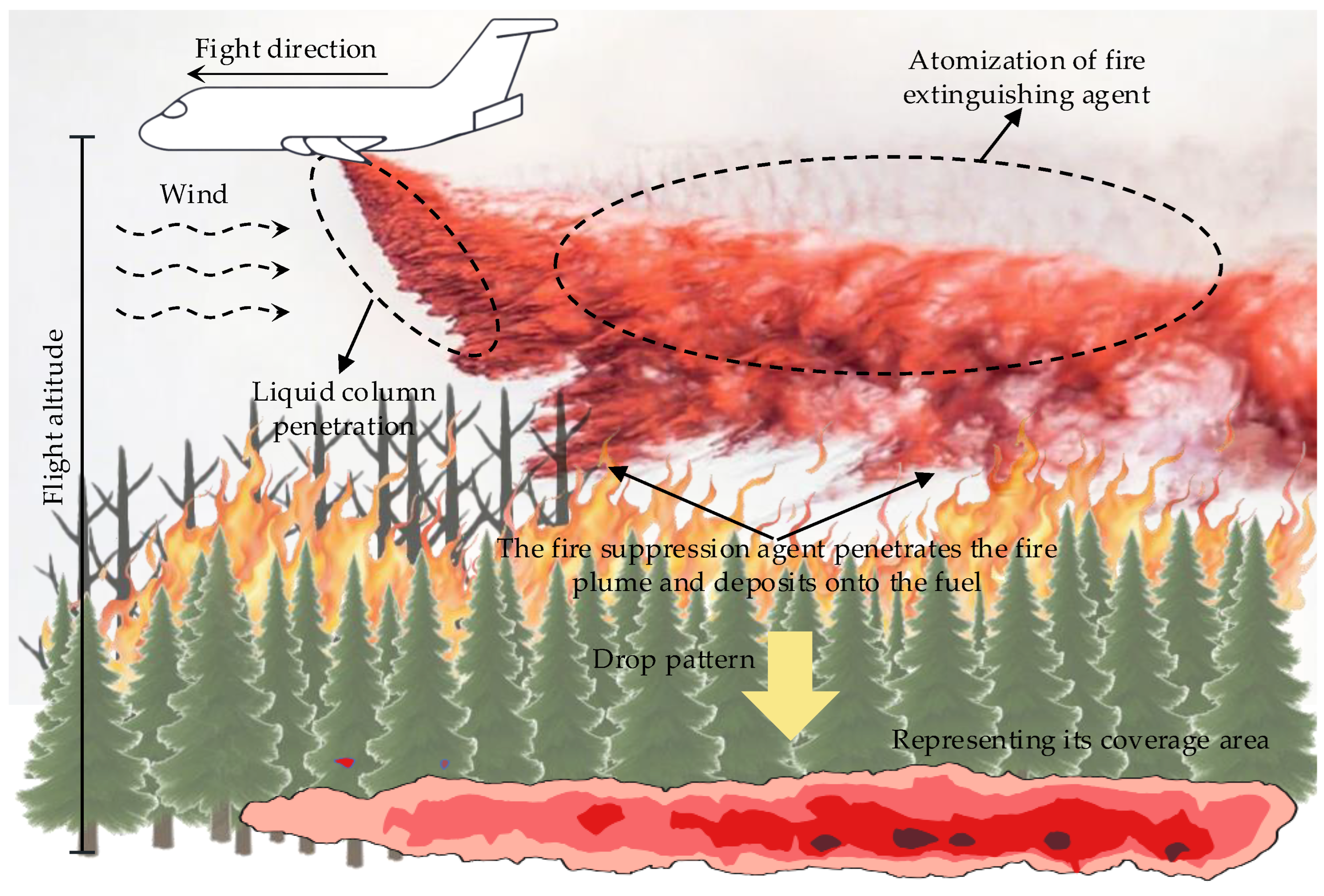
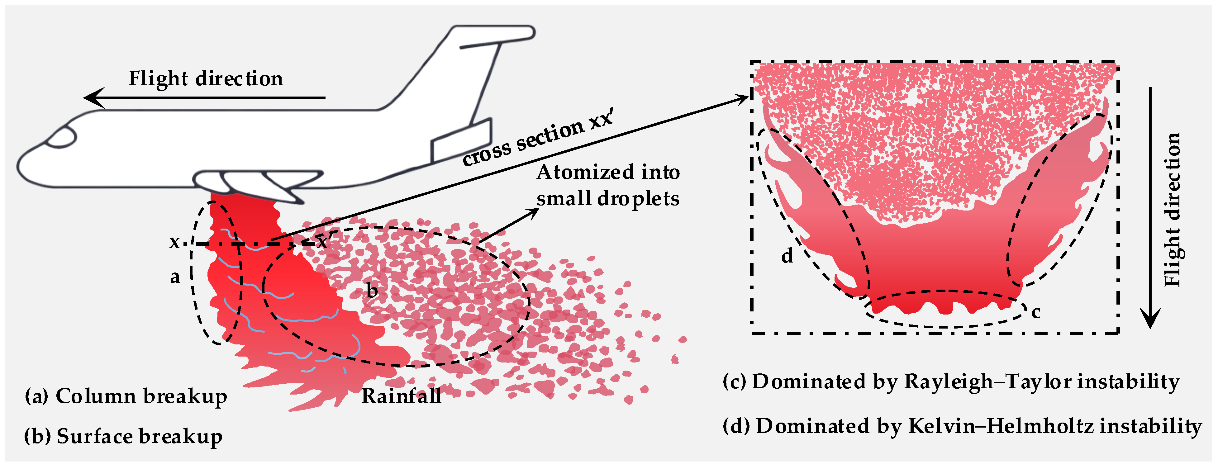
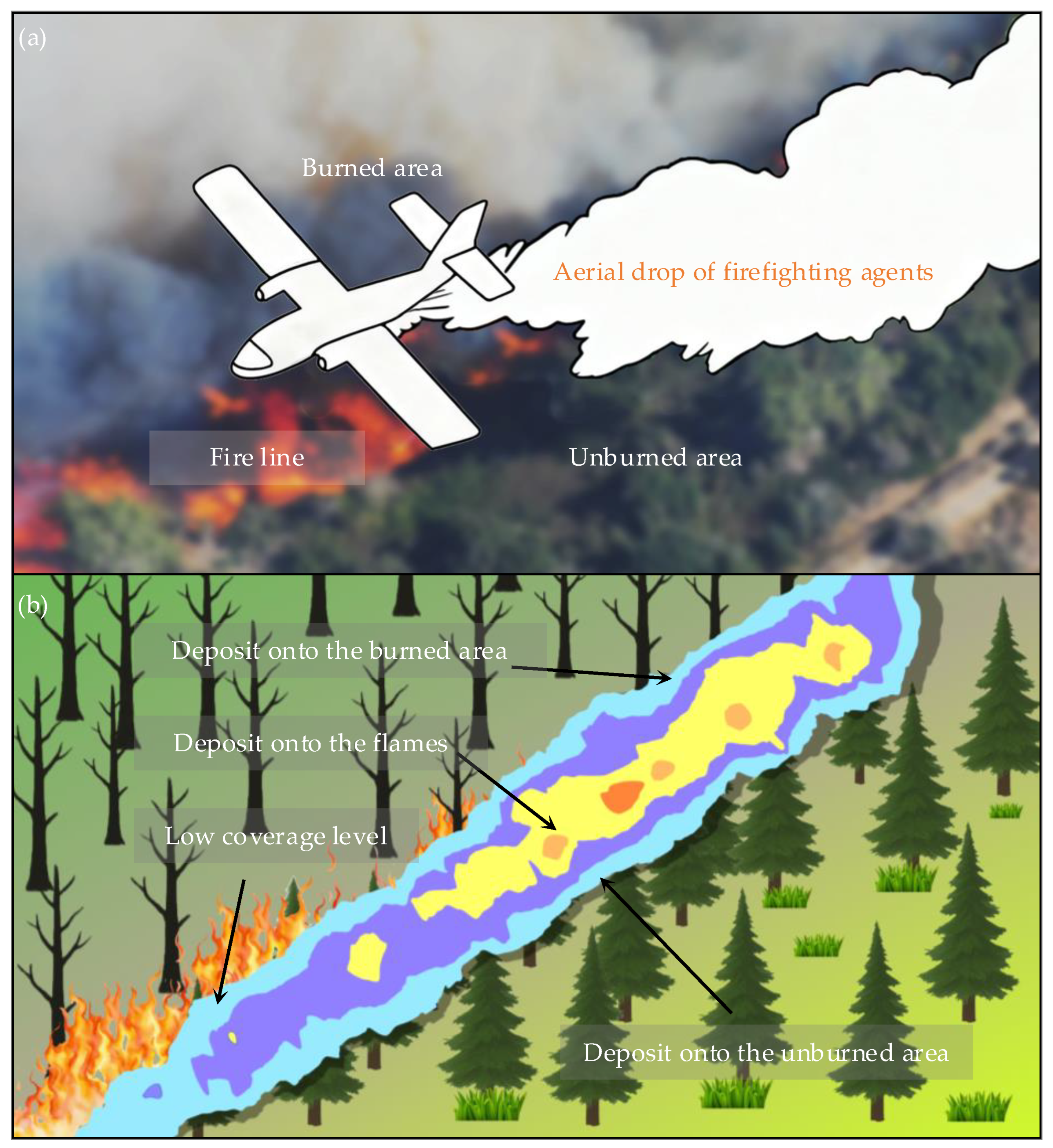
In aerial forest firefighting, aircraft either build firebreaks by dropping agent along the flanks of a fire or attack flames directly with rapid suppressant delivery [13]. Research has therefore focused on two core issues: in-flight drop dynamics and ground deposition patterns [14,15]. As shown in Figure 1, the released liquid forms a column that deforms, breaks up, and atomizes into droplets during descent. These droplets then penetrate the fire plume, deposit on fuels, and suppress combustion through cooling and smothering. Their behavior depends on flight conditions such as altitude and airspeed, meteorological conditions such as wind and turbulence, terrain complexity, and fire dynamics, including flame intensity and plume behavior. Suppression effectiveness further depends on fuel type, fuel moisture, and fire intensity [13,16,17,18]. This review synthesizes current knowledge of aerial agent dispersion, deposition, and suppression effectiveness, and highlights key limitations and future research needs.
These three parts of the review are best understood as a continuous mechanistic chain rather than independent topics: in-flight dispersion governs droplet breakup and transport, these processes shape ground deposition, and the resulting coverage determines suppression effectiveness. Although the literature has advanced understanding at each stage, major gaps remain across the full chain. In particular, five questions stand out: (1) How can breakup regime, droplet-size evolution, and final ground deposition be linked quantitatively under realistic aerial firefighting conditions? (2) How do fire intensity, fuel structure, terrain, ambient wind, and fire-induced plume dynamics jointly affect optimal drop altitude, flight speed, and release-system type? (3) What droplet-size distributions and coverage thresholds are needed for different objectives, such as direct attack on crown fires versus indirect firebreak construction? (4) How can existing empirical and theoretical models be extended and validated across aircraft platforms, suppressant properties, and atmospheric conditions? (5) How can real-time fireground information, aircraft availability, and resource scheduling be integrated with drop-physics and deposition models to support dynamic decision-making? Answering these questions would help move the field from isolated physical descriptions and empirical observations toward a unified predictive and decision-support framework for aerial forest firefighting.

2. Dispersion Mechanism of Aerial-Dropped Fire Extinguishing Agent

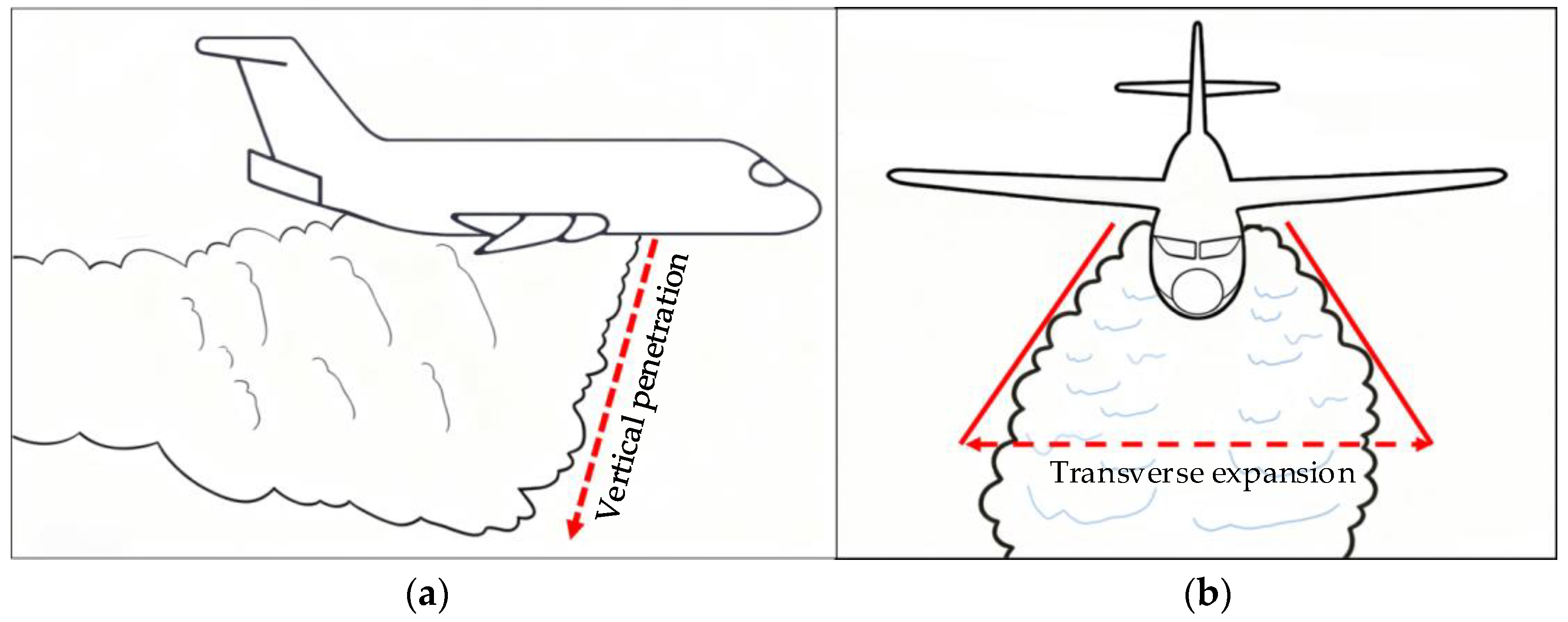
The aerial release of fire extinguishing agents is essentially a high-speed jet process controlled by deformation and breakup [19,20]. Because aerial firefighting uses large discharge openings rather than conventional small nozzles, the jet evolves in a more complex way during flight. The process can be divided into two related stages. The first is vertical penetration of the liquid column, driven mainly by initial jet momentum and gravity; this stage determines plume or canopy penetration and strongly affects ground coverage. The second is transverse expansion, governed by surface instabilities, aerodynamic drag, and surface tension, which stretch the liquid column into films and filaments [19]. Aerodynamic loading together with Rayleigh–Taylor (R-T) and Kelvin–Helmholtz (K-H) instabilities then drives secondary breakup and atomization into polydisperse droplets [15,21]. Current studies aim to quantify this evolution, including jet trajectory, deformation, and the resulting droplet-size distribution, because these factors are essential for predicting ground patterns, optimizing drop parameters, and improving aerial firefighting performance [15,22,23,24,25].

2.1. Deformation Characteristics of Fire Extinguishing Agent

After release from an aircraft, the liquid undergoes strong vertical and lateral deformation. Vertically, aerodynamic drag and impact alter the jet trajectory [15,25]. Laterally, crossflow shear bends and spreads the liquid column, as shown in Figure 2. Understanding this in-flight evolution is essential for improving drop performance and ground-coverage accuracy. Vertical penetration and transverse expansion depend on both liquid and airflow properties, including liquid velocity, density, surface tension, and viscosity, as well as air velocity, air density, and nozzle diameter [19,26]. These effects are commonly described by dimensionless groups such as the momentum ratio (q), Weber number (We), Froude number (Fr), and Reynolds number (Re) [14,20,27]. The Weber number measures the balance between inertial and surface-tension forces and is therefore closely related to breakup. The Froude number represents the ratio of inertial to gravitational forces and reflects vertical jet stability. The Reynolds number describes the balance between inertial and viscous forces and indicates the flow regime and spreading tendency. The momentum ratio compares jet momentum with crossflow momentum and is a key indicator of penetration depth [26,28]:
q = ρ l U l 2 ρ a U a 2 ,
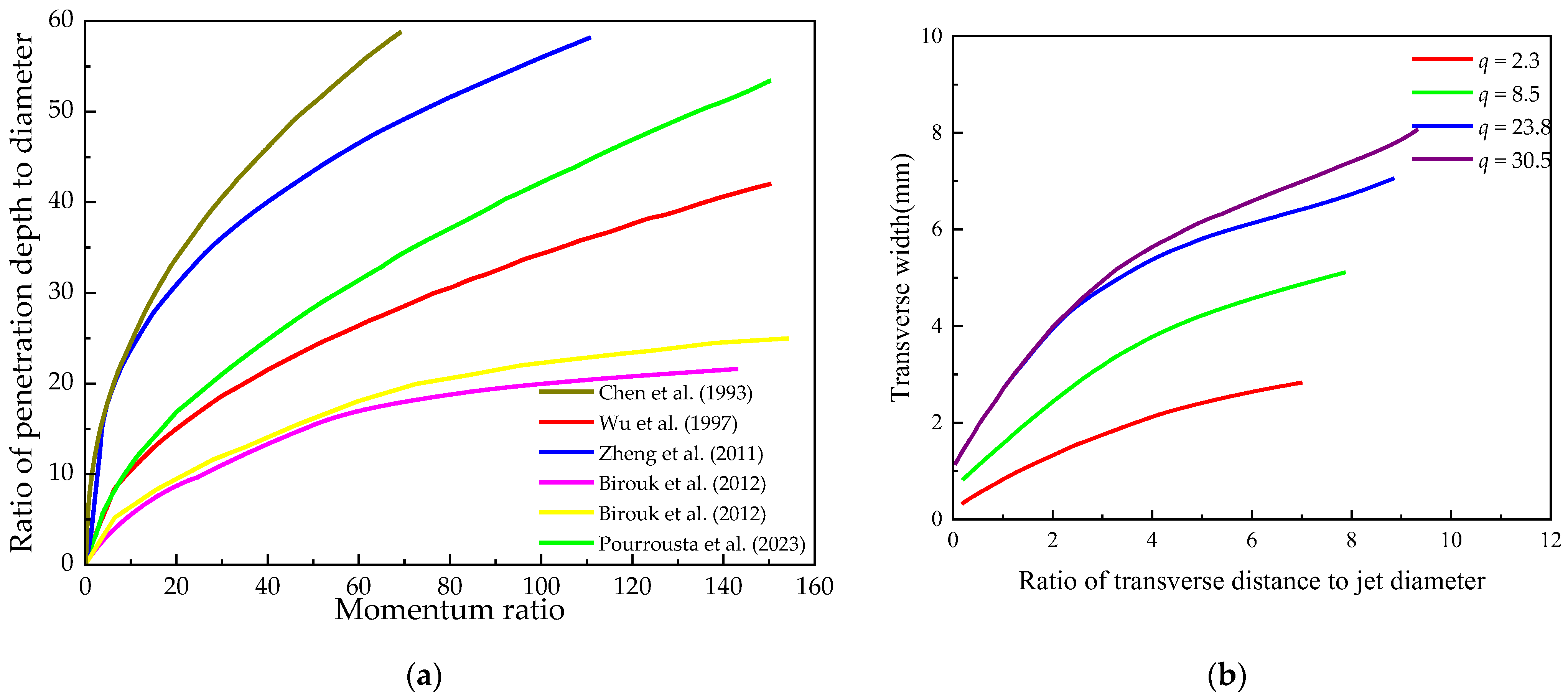
where ρl and ρa are the densities of the liquid and air, kg/m3. Ul is the liquid injection velocity, m/s, and Ua is the relative horizontal velocity between the surrounding air and the liquid, m/s. To interpret the literature, we relate the momentum ratio to two key performance indicators: vertical penetration and transverse expansion. Both directly affect drop effectiveness. As shown in Figure 3, changes in momentum ratio strongly influence both penetration depth and expansion width [19]. In general, both increase as the momentum ratio increases. Studying these trends helps predict jet trajectory [29] and, ultimately, the ground deposition pattern [23,30]. A high momentum ratio allows the jet to penetrate canopy layers and reach the target fire zone more effectively, which is advantageous for high-intensity fires. By contrast, a low momentum ratio makes the jet more sensitive to crosswind dispersion, producing broader coverage that may be useful for rapid control of large surface fires. Experimental studies and CFD simulations have quantified these effects.
Before breakup, jet deformation can be described mainly through changes in trajectory [25]. By measuring jet length or breakup-point location, which reflects vertical penetration depth, many studies [19,26] have identified a power-law relationship between penetration and momentum ratio: penetration increases as momentum ratio increases [29,35], as illustrated in Figure 3a. Rouaix et al. [19] used numerical simulations to increase the momentum ratio from 4.3 to 39 and reported roughly a twofold increase in penetration depth. Wu et al. [32] varied gas and liquid velocities in wind-tunnel tests, increasing the momentum ratio from 2 to 100, and found penetration depths ranging from 4 to nearly 100 nozzle diameters. Pourrousta et al. [28] studied small-scale jets and showed that increasing the momentum ratio from 5 to 211 extended the breakup-point distance by 94%. During penetration, the jet also spreads laterally under crossflow shear [19,34], and this transverse expansion is likewise controlled by momentum ratio [19,36]. Masuda and McDonell [35] examined distilled-liquid jets at T = 350–475 K and p = 3.7–6.4 atm with momentum ratios of 2.3–30.5. As shown in Figure 3b, higher momentum ratios produced stronger lateral spreading. This finding indicates that jet expansion depends not only on travel distance but also strongly on momentum ratio. As the momentum ratio increases, the wider transverse spread changes both the size and distribution of the final coverage area. BelloFiore et al. [37] also showed that increasing the gas density ratio, and thus the momentum ratio, caused the jet width to expand rapidly at first and then level off. Together, these studies clarify how environmental conditions affect jet behavior and provide a basis for optimizing aerial drops, especially in mountainous or high-altitude environments.
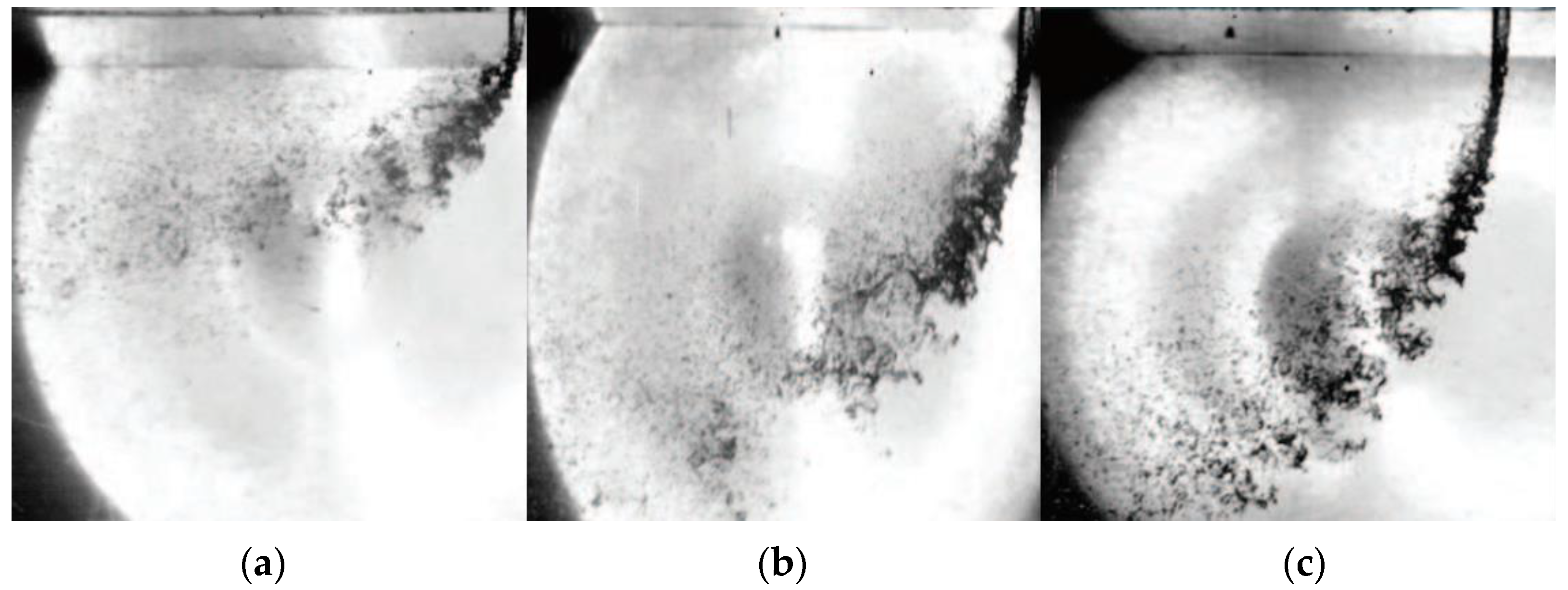
In summary, when the momentum ratio is low, jet inertia is small relative to the surrounding airflow. The jet, therefore, cannot overcome aerodynamic drag, bends more easily, and shows both shallow penetration and limited lateral spread. As the momentum ratio increases, jet inertia becomes dominant, allowing the liquid column to resist aerodynamic disturbance and maintain its structure, which increases both vertical penetration and transverse expansion. At still higher momentum ratios, airflow resistance becomes less important, the breakup point shifts downstream, and ambient-air entrainment further increases penetration and spread (Figure 4) [27,38,39,40]. From an operational perspective, high-momentum-ratio drops are better suited to crown fires and other high-intensity fires because they can better withstand strong thermal plumes and turbulence. Low-momentum-ratio drops are more suitable for surface or low-intensity fires without canopy obstruction because they promote aerodynamic shearing, faster breakup, and wider area coverage.
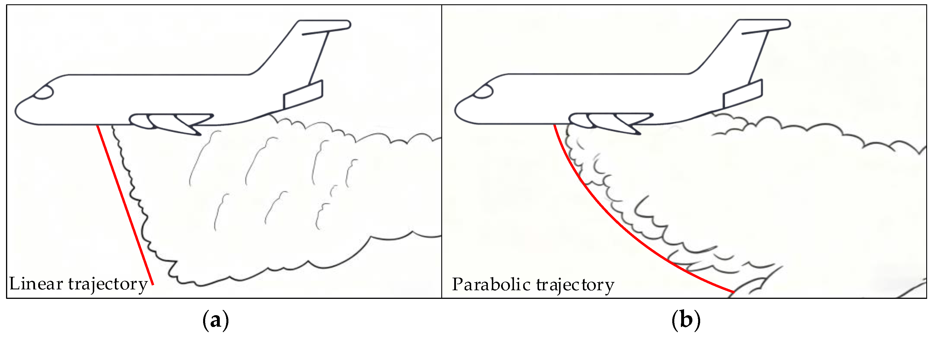
Momentum ratio influences not only penetration and expansion but also jet-trajectory shape. As shown in Figure 5, trajectories are generally classified as linear or parabolic. Wind-tunnel experiments by Ito et al. [14] showed that, at constant Froude number (Fr), trajectories tend to collapse onto a similar form. Using a pulsed shadowgraph technique, Wu et al. [28] proposed an empirical formula for jet trajectory, y / d = C 1 q C 2 , where d denotes the nozzle diameter, y denotes the distance of vertical penetration, and C1 and C2 are fitting parameters dependent on experimental conditions, fluid type, and environmental factors. Legendre [15] studied the effect of the Richardson number (Ri) in determining jet trajectory shape and classified trajectories as linear when (Ri < 1) and parabolic when (Ri > 1), establishing separate empirical models for each case. The linear trajectory model is expressed as x ≈ Cqy2/D (see Figure 5a), while the parabolic trajectory model is expressed as x ≈ CRiqy (see Figure 5b), where Ri = gD/Ul2, g represents gravitational acceleration, m/s2, x represents the distance of vertical penetration, and D is the characteristic diameter of the liquid jet, m. These studies collectively highlight the relationships between jet trajectory morphology and dimensionless numbers such as Fr and Ri, while also reinforcing the link between momentum ratio and vertical penetration depth. Therefore, optimizing aerial drop strategies should take into account fire intensity, terrain, and prevailing meteorological conditions. By incorporating appropriate trajectory models, operational parameters such as nozzle diameter and ejection velocity can be adjusted to improve the precision of fire extinguishing agent release and enhance the firefighting efficiency.

2.2. Breakup Characteristics of Fire Extinguishing Agent Jet

Jet breakup is the disintegration of a liquid jet into droplets under external forces such as crossflow air and gravity. It is commonly divided into two modes: column breakup (CBU) and surface breakup (SBU) [41], as shown in Figure 6. Understanding these mechanisms is essential for predicting droplet distribution and coverage range, and therefore for improving the uniformity and efficiency of agent deposition in the target area. Both breakup modes shape the initial droplet-size distribution, which is fundamental to any predictive model [22,42,43]. Column breakup usually occurs downstream of the release door. It is driven by the large density difference between the liquid jet and the surrounding air, which promotes Rayleigh–Taylor instabilities [44,45]. These instabilities rupture the jet core and produce relatively large liquid fragments. As the liquid travels farther from the door, the breakup continues, the column bends, and the fragments further atomize [44,45]. Surface breakup, by contrast, begins at the liquid–air interface [15]. There, the large velocity gradient triggers Kelvin–Helmholtz instabilities that continuously strip off films and filaments, which then fragment into many small droplets. Because surface breakup produces much finer droplets than column breakup, it generates a highly atomized droplet cloud [31]. These breakup differences strongly affect the ground deposition pattern [23,46] and thus the final coverage and suppression performance.
Experimental studies show that jet breakup depends strongly on flight conditions, especially drop altitude and airspeed. Increasing drop altitude lengthens the time during which the liquid is exposed to gravity and aerodynamic forces, promoting more complete breakup and producing smaller droplets [47,48,49]. Within a certain altitude range, breakup and collision-driven coalescence can reach a dynamic balance, so the mean droplet diameter eventually stabilizes [50,51]. Airspeed also shows a strong inverse relationship with droplet size. At low airspeed, droplet sizes are broader and generally larger, often following an approximately log-normal distribution. At high airspeed, droplets become smaller, and the size distribution becomes narrower [52,53]. Operationally, these results suggest that low-altitude, low-speed drops limit breakup and preserve penetration, which is advantageous for crown fires. By contrast, high-altitude, high-speed drops promote strong atomization and broader surface coverage, which may be more effective for open surface fires without dense canopy cover.
To improve predictions of droplet-size distributions, researchers have developed several empirical models based on experimental data [42,54]. A representative approach uses a statistical distribution normalized by a k-order Gamma function: Pk(x) = xk−1ekxkk/Γ(k). Kuznetsov et al. [43] analyzed experimental data from Magarvey and Taylor [48] to derive an empirical correlation for the mean droplet diameter (dm). This correlation couples key dimensionless numbers, specifically the Weber number (We) and Reynolds number (Re):
d m = ( k 1 × W e 0.5 + k 2 × R e 0.5 ) g ( Q × d k 3 × U a ) 1 6 ,
where dm represents the average diameter of the droplet, m; We = ρlv2δ/σ; Re = ρl/μ; δ represents characteristic dimensions of jet diameter, m; σ represents surface tension, N/m; μ represents the viscosity of a liquid, Pa·s; v is the relative velocity of gases and liquids, m/s; Q represents volumetric flow rate, m3/s; k1, k2, and k3 are empirical coefficients. Equation (2) provides a useful framework for linking the atomization behavior of aerially released fire extinguishing agents to key physical and aerodynamic parameters. By combining the Weber and Reynolds numbers, it captures the effects of inertia, surface tension, viscosity, and gas–liquid relative motion on droplet breakup and mean droplet size. The model therefore helps explain how flight conditions, discharge conditions, and liquid properties jointly shape the final dispersion state of the extinguishing agent. Because droplet size also affects evaporation loss, canopy penetration, ground deposition, and suppression effectiveness, Equation (2) forms an important link between breakup physics and practical aerial firefighting performance.
This model quantitatively links mean droplet diameter to the key dimensionless parameters governing atomization. A higher Weber number implies stronger inertial effects relative to surface tension and therefore more intense breakup. A higher Reynolds number indicates stronger turbulence and likewise promotes droplet fragmentation [54]. Under stronger inertia and turbulence, the number of secondary droplets increases, and their characteristic size decreases, so the mean droplet diameter (dm) is inversely related to both We and Re. Under high flow-rate conditions (10–15 L/s), Equation (2) predicts mean droplet diameter with good accuracy, with typical deviations from measurements below 10% [43]. This level of agreement makes the model useful for practical optimization of suppression strategies.
The transition from in-flight breakup to final ground deposition is governed largely by the resulting droplet-size distribution. Column breakup tends to produce larger fragments, whereas surface breakup produces finer droplets. This distinction matters because small droplets are more easily advected by ambient air and evaporated, increasing drift and potentially reducing local coverage, while larger droplets are more stable during descent and penetrate vegetation and fire plumes more effectively. Momentum ratio further affects the final deposition pattern by controlling not only vertical penetration but also transverse expansion. Even so, the current literature still lacks enough direct quantitative evidence to establish a universal coupling among breakup regime, droplet-size evolution, and final ground deposition under realistic aerial firefighting conditions. Resolving this gap remains an important direction for future research.
Overall, research on the deformation and breakup of aerially released fire extinguishing agents has advanced considerably, but most studies still rely on simplified experiments and idealized analysis. Future work should focus more directly on realistic aerial firefighting conditions and, in particular, on the coupled effects of aircraft operating parameters, ambient crosswind, fire-induced updrafts, complex terrain, and canopy structure on penetration, expansion, and trajectory evolution. Most wind-tunnel studies and simulations have used water or water-like liquids, and the limited work on other fluids suggests that the main breakup behavior remains broadly similar because the same instability mechanisms and dimensionless groups still dominate. However, the applicability of current trajectory and penetration models to practical retardants with different physicochemical properties and under varying atmospheric conditions still needs to be tested. More full-scale experiments and high-fidelity multiphase simulations are also needed to bridge the gap between laboratory studies and real operations. More broadly, future studies should move beyond isolated descriptions of jet deformation and build an integrated framework that links in-flight deformation, droplet breakup, ground deposition, coverage level, and actual suppression effectiveness.

3. Deposition Mechanism of Aerial-Dropped Fire Extinguishing Agent

As discussed above, the final coverage area and coverage level are controlled by the preceding dispersion and deposition processes. Together with droplet size and fire conditions, these deposition characteristics determine practical suppression effectiveness [21,55]. In practice, however, ground deposition is often highly non-uniform because droplet trajectories are shaped by several interacting environmental factors. Ambient wind speed and direction [27,56] can displace droplets from their intended paths, flight altitude [23,57] changes airborne residence time and thus the landing position, and flight speed [58], together with initial ejection velocity, controls the longitudinal extent of the drop pattern. Temperature, atmospheric turbulence, and terrain further modify local airflow and droplet evaporation, which also changes deposition. To clarify these effects, researchers have combined high-fidelity numerical simulations [56,59,60], controlled wind-tunnel experiments [14,23], and full-scale drop tests [30,55,61]. The goal is to develop predictive models for diverse operating and environmental conditions and thereby support better aerial firefighting strategies [62].

3.1. Coverage Area of Fire Extinguishing Agent

After release from the aircraft, the fire extinguishing agent breaks up, expands, and settles before forming a ground coverage area. To estimate that area, Legendre et al. [58] derived empirical expressions for coverage length (L) and width (λ). Coverage length was controlled mainly by aircraft ground-relative speed (Ua) and drop duration (T); the primary contribution was assumed to be the distance traveled by the aircraft during the drop, i.e., UaT, where T represents the duration of the liquid decline, s. Because measured ground patterns were consistently longer than UaT, an additional longitudinal-dispersion term proportional to pattern width was introduced. The resulting empirical expression for coverage length is
L = U a T + f 1 λ ,
where f1 is the empirical coefficient; λ represents the coverage width, m. For the lateral coverage width (λ), dimensional analysis indicated that the dominant controlling parameter is the momentum ratio (q), which is consistent with classical studies of liquid jets in crossflow. The appropriate characteristic length scale was identified as ds = S1/2, where S is the exit area of the release door or nozzle, m2. This effect is particularly evident in a pressurized system, where higher injection velocity and increased inertia result in broader dispersion. The empirical formula for estimating the lateral coverage width is expressed as
λ = f 2 S 1 / 2 q 1 / 5 ,
where f2 is the empirical coefficient; q represents the momentum ratio. The empirical parameters f1 and f2 vary under different conditions. When the wind speed is less than 1.5 m/s, the value of the empirical coefficient f1 is 2, and the value of the empirical coefficient f2 is 27 in a gravity feed system and 58 in a pressurized system [63]. Experiments at the CEREN laboratory in France validated the model under these low-wind conditions [58]. However, its predictive accuracy declines markedly when wind speed exceeds 1.5 m/s, showing that it remains a low-wind empirical model. Based on the literature reviewed here, no universally validated coverage model yet exists for higher wind speeds. Extending prediction to wind speeds above 1.5 m/s is therefore an important research priority. Such a model will likely need to include mean-wind advection, wind direction, atmospheric turbulence, droplet breakup and size evolution, drag, gravitational settling, evaporation, fire–plume interaction, and terrain and canopy effects, so that the final ground pattern can be predicted within an integrated multiphysics framework rather than by empirical extrapolation alone. Coverage area also depends strongly on the delivery system and flight conditions [21]. The two main aerial delivery systems are gravity-feed and pressurized systems [21,63], and they produce different deposition patterns. Gravity-feed systems rely on gravity to discharge the liquid, giving them a simple structure and broad compatibility with different agents. Pressurized systems use pumps or compressed gas to increase tank pressure and release velocity, which intensifies shear, promotes finer atomization, and increases lateral momentum. As a result, they generally produce broader and more uniform coverage than gravity-feed systems [60,63].
Flight conditions strongly influence the coverage area by controlling droplet dynamics. Experimental and numerical studies have quantified the effects of altitude and speed. Suter [61] and Qureshi et al. [64] analyzed coverage patterns under different flight conditions by varying altitude and velocity. Based on Froude-number similarity, Yang et al. [23] used wind-tunnel experiments to examine how airflow conditions affect coverage. Guan et al. [56] used a Smoothed Particle Hydrodynamics (SPH) model, and Sun et al. [46] incorporated full-scale aircraft data to quantify the relationship between coverage area and flight parameters. Lower drop altitudes limit plume expansion and therefore produce smaller, more regular coverage areas. Higher altitudes increase airborne residence time and allow longer interaction with the surrounding air, which broadens dispersion. Flight speed affects the pattern differently: higher speed gives the liquid more initial horizontal momentum, stretches the plume downwind, increases the coverage aspect ratio, and concentrates deposition along the flight path. As shown in Table 1, deposition patterns vary substantially across aircraft types and operating conditions. With respect to the delivery system, the B-747 pressurized system produces a more uniform pattern than the DC-10 gravity-feed system, with more continuous and concentrated high-coverage zones. With respect to altitude, the B-747 operates at a higher altitude than the MAFFS II 2008 and achieves broader dispersion because of the longer air-interaction time, which reduces the aspect ratio. Similarly, the S-64 Erickson flies higher than the Bambi Bucket 2K and produces a wider spread for the same reason. With respect to speed, the Lockheed P-3 Orion flies faster than the Air Tractor AT-802, giving the liquid greater initial horizontal momentum and stretching the plume more strongly in the downwind direction, which increases the aspect ratio. These results show that altitude and speed must be adjusted together to optimize coverage. Higher altitudes are preferable when wider lateral coverage is needed, as in firebreak construction, whereas higher flight speeds may be more suitable when stronger longitudinal coverage is required, as in direct engagement with a flame front.

3.2. Coverage Level of Fire Retardant

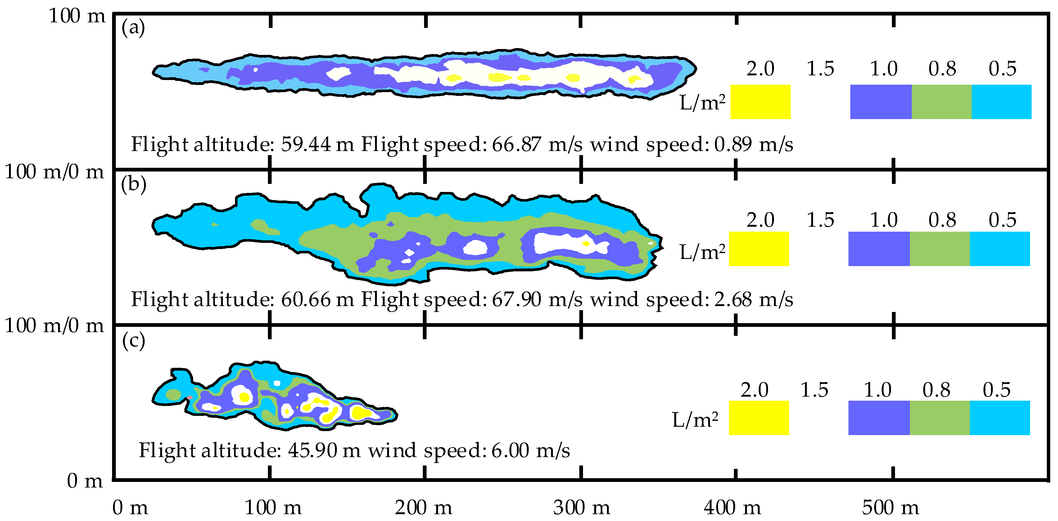
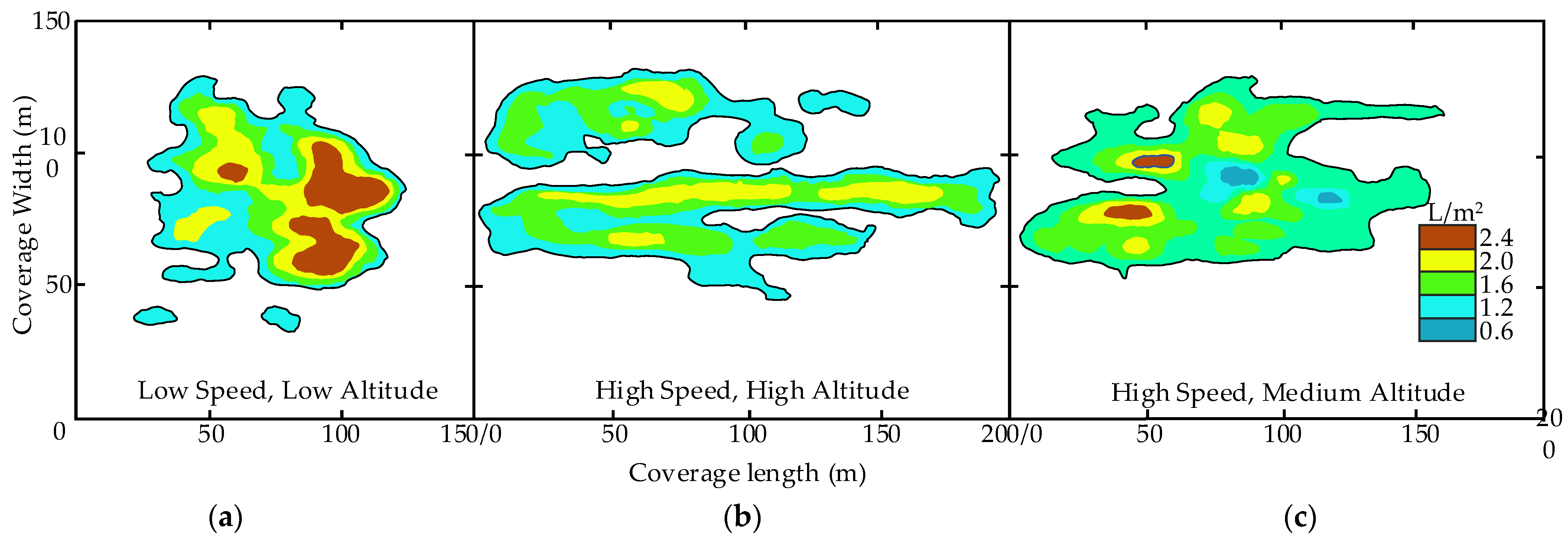
Coverage level, defined as ground deposition per unit area, is a key determinant of aerial-drop effectiveness. It is strongly affected by flight altitude, flight speed, and wind speed. Figure 7 shows coverage-level distributions for the CDF S2F Turbo under different conditions [65]. Compared with Figure 8a, the stronger wind in Figure 7b increases airflow shear, disperses the liquid more widely, and reduces the uniformity of coverage. In Figure 7c, the lower flight altitude shortens airborne time and produces a more concentrated coverage area, although the stronger wind still disperses the highest-coverage regions. Figure 8 shows the coverage-level distribution for 12 m3 simultaneous drops from the AG600 amphibious aircraft under different conditions [30]. Under low-speed, low-altitude conditions, the highest-coverage zones are larger and concentrated mainly upstream along the flight path. Under high-speed, high-altitude conditions, overall coverage level decreases, but the pattern becomes more uniform, and the high-coverage zones are more elongated. Under high-speed, moderate-altitude conditions, the high-coverage zones expand more strongly.
In aerial forest firefighting, researchers have studied the effects of flight conditions on coverage level using numerical simulations, theoretical models, and full-scale experiments. Numerical studies have focused on the main factors controlling coverage distributions and on predictive models that account for interactions between flight conditions and the environment. Amorim [65] developed a simulation framework that explicitly includes wind speed, wind direction, and flight altitude, providing a basis for optimizing drop tactics through quantitative analysis of ground patterns. To capture the transient physics of liquid dispersal, Guan et al. [56] used a Smoothed Particle Hydrodynamics (SPH) method in which the fire extinguishing agent is represented by Lagrangian particles; this method reproduces breakup, coalescence, and splashing and therefore allows high-fidelity evaluation of how flight parameters affect coverage level. Using data from full-scale aircraft and wind-tunnel tests, Sun et al. [46] simulated the effects of velocity, altitude, and attitude on coverage level and provided guidance for parameter optimization. Experimental studies by Suter [61] and Qureshi et al. [64], as well as scaled wind-tunnel tests by Ito et al. [14], measured key coverage metrics including area, density, and uniformity under varying meteorological and flight conditions. Overall, these studies show that low-altitude, low-speed drops shorten the ballistic trajectory and reduce airborne time, which limits aerodynamic disturbance and produces concentrated deposition with high local coverage. Such conditions are advantageous for high-intensity fires. In contrast, high-altitude, high-speed drops increase droplet disruption, broaden the coverage area, and reduce local coverage density; they may therefore be suitable for low-intensity fires but are less effective against high-intensity fires. Coverage level also increases approximately linearly with mass flow rate, because a higher flow rate increases the volume released per unit time, although this relationship weakens at high altitude or high speed because aerodynamic interference becomes stronger. To predict spatial distribution, Legendre et al. [63] proposed that coverage level can be approximated by a two-dimensional Gaussian profile and, using volume conservation for the effective deposited liquid, derived the maximum centerline coverage level. Combining that Gaussian assumption with the previously derived expressions for pattern length and width yields the following coverage-level equation:
η ¯ ( y ) = η max exp [ y 2 / 2 λ 0 2 ] ,
where η ¯ represents the coverage contour, L/m2; ηmax represents the highest coverage level within the coverage area, L/m2; y represents the coverage width; λ0λ/2(ln(2))1/2, λ represents the coverage width, m. The model was derived from full-scale drop data collected from a B-747 fixed-wing aircraft, a Columbia BV-107 helicopter equipped with a 1000-gallon bucket, and a CDF S-2T aircraft using a fixed water tank. Its validity was further confirmed through comparisons with data from other aircraft models [63]. Equation (5) enables the estimation of fire extinguishing agent coverage levels across the entire drop zone. By calculating and adjusting flight altitude, velocity, and mass flow rate of fire extinguishing agent based on fire scenarios and operational constraints, the target area can maintain coverage above the effective threshold, optimizing fire suppression efficacy.
Overall, substantial progress has been made in understanding the coverage area and coverage level of aerially delivered fire extinguishing agents. However, current research still relies heavily on simplified empirical models, limited full-scale experiments, and relatively idealized atmospheric conditions. Future work should focus more on the coupled effects of delivery-system type, aircraft operating parameters, ambient wind, complex terrain, forest canopy structure, and the physicochemical properties of the agent on ground deposition. In particular, more robust predictive frameworks are needed to describe coverage area, coverage-level distribution, and spatial uniformity simultaneously under realistic aerial firefighting conditions. More full-scale drop tests and high-fidelity numerical simulations are also needed to improve model applicability across aircraft platforms and operating environments.

4. Effectiveness of Aerial-Dropped Fire Extinguishing Agent

The effectiveness of aerial forest fire suppression depends on how well the fire extinguishing agent alters fire behavior, and it is controlled by several interacting factors. Fuel type is fundamental because the physical and physicochemical properties of vegetation determine combustion behavior and sensitivity to different agents. The agent itself also matters, especially droplet size after atomization. Droplet size influences fall velocity, canopy penetration, surface coverage, and flame contact efficiency, and thereby affects cooling, oxygen isolation, and suppression of combustion reactions. Response time is another critical factor. It includes detection, dispatch, and travel time to the fireground, and it is especially important during the early stages of a fire, when timely intervention may prevent escalation into high-intensity surface or crown fire. In addition, aircraft number, flight speed, and the accuracy and timeliness of fireground information all influence resource deployment and suppression success. Understanding how these factors interact is therefore essential for effective aerial firefighting and efficient resource allocation.

4.1. Quantitative Modeling of Fire Suppression Effectiveness

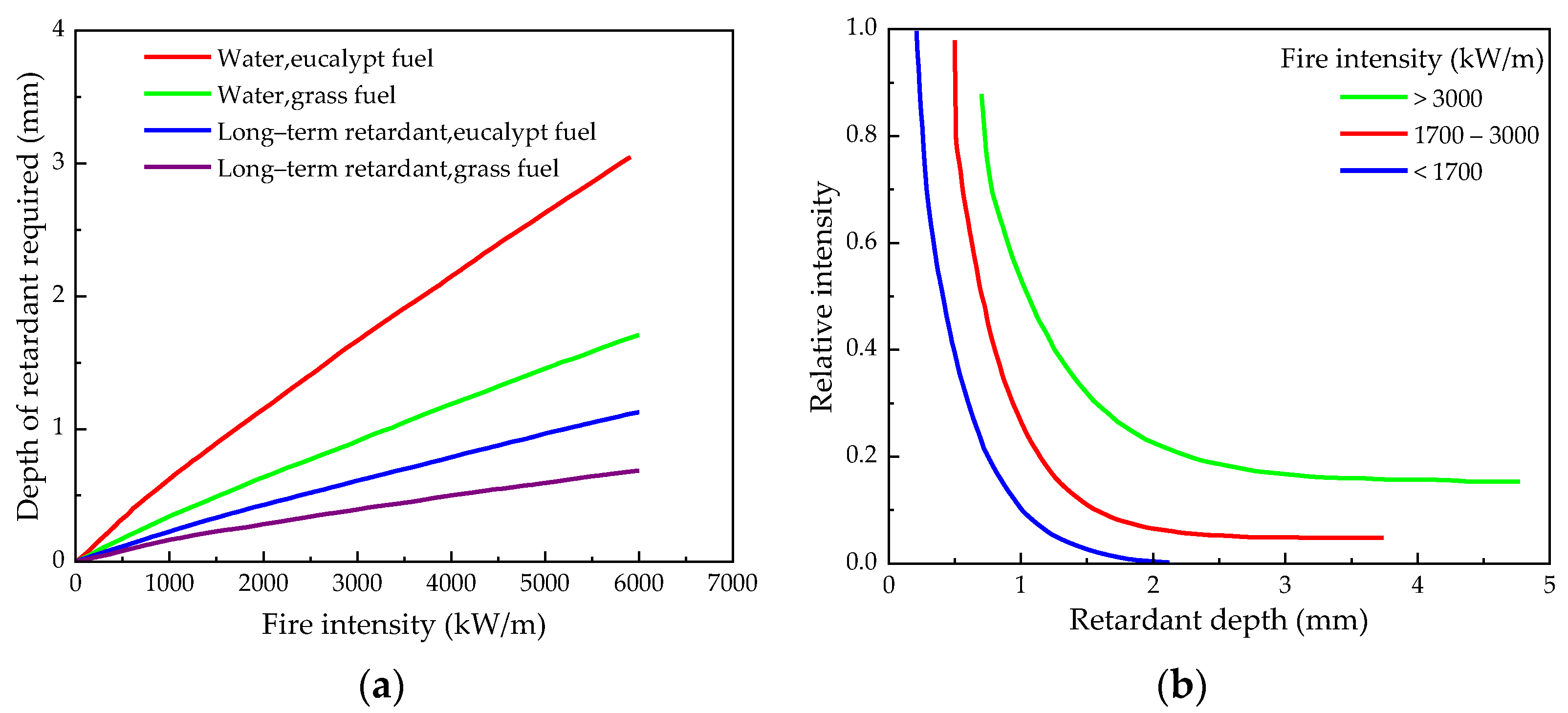
In practical wildfire suppression, fire intensity, vegetation type, and initial fire size are key variables in resource allocation. Together, they determine the required volume of fire extinguishing agent, the mass flow rate needed to achieve the target coverage level, and ultimately the likelihood of successful containment [66,67]. As shown in Figure 9a, required coverage levels vary substantially with fuel type because fire intensity differs across vegetation. Eucalyptus forests, which have high fuel loads and oil content, require much higher coverage thresholds than grasslands [68]. These thresholds also rise with increasing fire intensity. Figure 9b shows a negative relationship between coverage level and relative flame intensity, defined as the ratio of post-drop flame intensity to initial flame intensity, indicating that higher coverage levels reduce flames more rapidly. Firefighting strategies should therefore be adjusted to vegetation type and fire stage so that resources can be allocated more efficiently.
Before suppression begins, fire intensity should be estimated as accurately as possible so that resources can be allocated appropriately. Flame intensity is commonly classified by heat release rate as low (<1700 kW/m), moderate (1700–3000 kW/m), or high (>3000 kW/m) [9,17]. Stechishen and Little [68] and Hansen [69] showed that low-intensity flames may require only 0.2 L/m2 of water coverage, whereas high-intensity flames require at least 1.2 L/m2. When direct intensity estimates are unavailable, vegetation type can be used as a practical basis for planning. According to Restás [18] and Delforge [70], grassland fires typically require at least 0.4 L/m2 of coverage, while tall shrubland requires at least 1.6 L/m2; this threshold rises to 2.4 L/m2 when the shrub layer contains large amounts of dead woody fuel. In addition, the applied line width should be 2 to 2.5 times the fire-front width, because a narrower line substantially increases the risk of fire-line breach and suppression failure. Loane and Gould [17] further quantified the relationship between flame intensity and coverage level. As shown in Figure 9b, increasing the initial coverage level reduces fire intensity markedly, especially at low intensities, although the marginal benefit decreases beyond a critical point. Higher flame intensities, therefore, require proportionally higher coverage to achieve suppression. Under resource constraints, identifying the optimum coverage threshold is essential for maximizing suppression efficiency.
To estimate water demand more precisely, Hansen [69] derived a critical water flow-rate equation from the fire-point equilibrium theory proposed by Rasbash [71] and Beyler [72]. The formulation incorporates key thermal terms, including heat release from fuel combustion, external heat flux, and heat absorbed through water evaporation. The resulting critical water flow rate is given by
m ˙ water , cr = m ˙ water , cr , 0 + q ˙ E η water × L v , water ,
where m ˙ water , cr denotes the critical water application volume, kg·m−2·s−1; m ˙ water , cr , 0 represents the critical water application volume without external heat flow, kg·m−2·s−1; q ˙ E is the external heat flux, kW·m−2; ηwater signifies water use efficiency; Lv,water corresponds to the enthalpy change in water at 291 K; and water vapor at 373 K is approximately 2559.8 kJ·kg−1. Based on fire department operational data, Thomas [73] and Baldwin [74] proposed a formula for determining the required water application duration for effective suppression, as a function of burned area. For fire areas exceeding 20 m2, the necessary water application time is given by
t = 100 × A f i r e 0.559 ,
while for fire areas greater than 200 m2, the required water application time is expressed by the following equation:
t = 198 × A f i r e 0.5 ,
where Afire represents the flame’s burning area. Combining the critical water flow-rate equation with the water-application time relations provides a practical estimate of the water required for a suppression operation. In real conditions, however, extreme weather such as high temperature and strong wind can directly alter agent coverage and reduce suppression effectiveness. Using infrared imaging, Pérez et al. [75] quantified convective losses and showed that under extreme conditions, only a limited fraction of the dropped agent reaches the target area, with cooling efficiency reduced by 43%; in some cases, only about 10% of the deployed agent is effectively delivered and used within the fire zone. High-intensity fire plumes can further disrupt drop coverage. When flame intensity exceeds 3000 kW/m, the loss rate under conventional elliptical drop patterns can reach 87.8%. Although some of the agents landing outside the target may still contribute indirectly, it greatly reduces the efficiency of direct suppression [9]. Another issue is that deposited coverage is rarely spatially uniform. As discussed in Section 3.2, the coverage-level distribution can often be approximated by a two-dimensional Gaussian profile, with the highest deposition near the centerline and progressively lower deposition toward the edges. As a result, first-order estimates based on average flow rate or average coverage may overstate true effectiveness. Suppression depends more directly on whether local coverage exceeds the required threshold across the target area. Coverage heterogeneity can therefore lower suppression probability by creating sub-threshold regions even when the average deposited amount appears sufficient. This problem is especially important under high-altitude, high-speed, strong-wind, or high-intensity-fire conditions, when the pattern becomes broader, thinner, and less uniform. As shown in Figure 10, part of the dropped agent may also land on fully burned ground and provide no suppression benefit, while the pattern edges frequently remain below threshold [66]. In addition, some of the agent forms a liquid zone in front of the fire, but under very high flame intensity, much of this liquid evaporates rapidly, shortening residence time and limiting suppression effectiveness [76]. Drop strategies must, therefore, account explicitly for plume disturbance, coverage heterogeneity, edge losses, and evaporation.
In addition to the total amount applied, droplet size after atomization strongly affects suppression effectiveness [67,77]. As discussed earlier, environmental conditions shape the droplet-size distribution after breakup. In general, atomized agents can be divided into fine droplets (mist) and large droplets [77]. Fine mist has a larger specific surface area, which enhances heat and mass transfer. It can enter fuel micropores, displace oxygen, and form protective water films, thereby reducing fuel temperature and inhibiting pyrolysis. Antonov et al. [77] reported that fine mist can displace pore oxygen and form water films about 2 mm thick, reducing internal fuel temperature below 600 K. Under those conditions, residual heat may be insufficient to sustain combustion even after spraying stops, making fine mist especially effective for internal cooling and re-ignition prevention in dense fuels [78]. Fine droplets also disperse well and can cover a larger area, which helps limit fire spread. Their main disadvantage is that they are more easily deflected by wind and more prone to evaporation under high temperatures [75,79], which can greatly reduce effective coverage in strong plumes or windy conditions. Large droplets, by contrast, have greater mass and therefore resist evaporation and aerodynamic shear more effectively [80]. They penetrate flames and dense smoke better and are better suited to rapid cooling in high-intensity fire cores. Although they may be slightly less efficient than fine mist on a per-unit-mass basis and may increase extinguishment time by 10–15% [77], their greater deposition stability and thicker local coverage support rapid localized suppression. Their limitation is weaker dispersal, which makes them less effective for broad-area control [67].

4.2. Optimization Strategies for Aerial Suppression Efficiency

Suppression efficiency is a central metric for evaluating aerial forest firefighting systems because it reflects how effectively a fire can be controlled within a limited time window. It depends on the interaction of many factors. In addition to the physical variables discussed above, such as fuel type, droplet-size distribution, and deposition pattern, operational variables such as aircraft number and flight speed also govern delivery precision and overall effectiveness. Suppression efficiency is therefore strongly scenario dependent.
Aircraft number, flight speed [81], and the accuracy of fireground information [82] all have major effects on suppression outcomes. Among them, the aircraft number appears to be the most decisive. Based on the System of Systems (SoS) model of Prakasha et al. [83], containing a 1.2 ha ignition within a 20 min dispatch window requires at least eight aircraft. Smaller fleets fail regardless of platform type, including belly-tank helicopters, fixed-wing airtankers, and helibuckets. With ten aircraft, containment is achieved only by high-capacity platforms such as compound helicopters or VTOL aircraft; low-capacity platforms such as multirotors or tiltrotors remain ineffective. Consistent containment across all platform types requires twelve or more aircraft [81]. Flight speed is also important. At 20 m/s, a lower speed improves placement precision but limits spread, reducing operational efficiency and causing failure in low-payload aircraft. Increasing speed to 30 m/s improves suppression performance across configurations for small burned areas. At 40 m/s, however, energy use rises, endurance falls, and refueling becomes more frequent, which lowers overall success rates. In addition, reduced air density at altitude may increase stall risk if the speed is too low. Optimum speed, therefore, requires a balance between suppression performance and flight safety. Real-time fireground information is equally important. Using a fuzzy goal programming risk function, Zhan et al. [82], and using a coordinated collaboration algorithm, Shahparvari et al. [83], showed that timely information updates can reduce suppression risk by about 13% and, through better coordination and resource scheduling, reduce firefighting time by about 11%. Increasing the update frequency from once per hour to once every 10 min further improves suppression success [82]. Effective aerial firefighting, therefore, requires sufficient aircraft, platform-specific optimization of speed and trajectory, and continuous information updates so that deployment and resource allocation can be adjusted in real time.
Taken together, the evidence reviewed in Section 2, Section 3 and Section 4 shows that no single drop strategy is optimal for all fires. Instead, droplet characteristics, flight parameters, deposition patterns, and required coverage must be matched to the specific fire scenario. High-intensity or crown fires require stronger penetration through flames, smoke, and canopy, together with higher local coverage density. These conditions are better achieved with relatively larger droplets and more concentrated drops, such as low-altitude, low-speed delivery. Low-intensity surface fires and firebreak construction, by contrast, benefit more from broader spatial coverage, for which finer droplets and wider dispersion may be preferable.
Although major progress has been made in modeling aerial suppression effectiveness and improving operational efficiency, current studies still depend heavily on simplified assumptions about fire behavior, agent transport, and aircraft deployment. Future research should integrate fire-intensity evolution, vegetation characteristics, droplet-size-dependent suppression mechanisms, and ground deposition into a unified evaluation framework. Particular attention is needed on the coupled effects of extreme weather, fire-plume dynamics, evaporative loss, and sub-threshold edge coverage under realistic conditions. Existing theoretical and empirical models also need further refinement through full-scale experiments, high-fidelity multiphase simulations, and cross-platform validation. More broadly, the field should move beyond static estimates of agent demand and develop dynamic decision-support frameworks that integrate aircraft number, flight parameters, real-time fireground information, and resource scheduling to improve the precision, adaptability, and overall effectiveness of aerial forest firefighting.

5. Conclusions

Overall, the reviewed literature supports a unified view of aerial firefighting effectiveness. Drop dispersion, ground deposition, and suppression effectiveness are not separate issues but successive links in one causal chain. Flight conditions and release-system characteristics determine jet penetration, breakup, and droplet-size evolution; these processes then control the spatial extent, uniformity, and local density of ground deposition; and the resulting deposition pattern governs suppression performance under different fire scenarios. This synthesis suggests several practical implications. High-intensity or crown fires generally require more concentrated delivery that provides stronger penetration and higher local coverage. Low-intensity surface fires and firebreak construction benefit more from broader dispersion and wider area coverage. Release-system choice should also reflect the target deposition pattern, with pressurized systems generally favoring wider and more uniform coverage.
On the suppressant agent drop itself, three points to note:
(1)
As the inertia of the suppressant agent jet is smaller than that of the gas, the kinetic energy of the liquid column is insufficient to overcome air resistance at a low momentum ratio. As a result, the liquid column is easily disturbed by airflow, leading to shape bending, shallower vertical penetration depth, and smaller transverse expansion range. When the momentum ratio increases, the inertia of the suppressant agent jet relative to that of the gas increases. Airflow resistance was reduced, and the shape of the jet did not change. Both vertical penetration depth and transverse expansion range of the liquid column increased.
(2)
At higher liquid discharge height within a certain range, the liquid is under gravity and air resistance for a longer time. A more complete droplet breakup process resulted. Therefore, droplet diameter decreases with height increase.
(3)
For discharge velocity at lower airspeeds, the droplet size distribution has a wider range. The larger droplet diameters follow a log-normal distribution function. At higher airspeeds, the droplet size distribution curve becomes narrower with smaller droplet diameters.
There are three points to note for the suppressant agent ground pattern:
(1)
Gravity Feed Systems have a relatively simpler structure and are easily used for different types of suppressant agents. The pressurized system needs mechanical devices such as pumps or compressed gases to apply pressure to the suppressant agent storage tank to increase the velocity of the liquid drops. The suppressant agent is then exposed to greater shear forces and breaks down into smaller droplets in the air. These smaller droplets can then diffuse more effectively with the airflow to give a larger coverage area. Compared to the Gravity Feed Systems, the pressurized system provides more uniform coverage and a larger coverage area for the suppressant agent.
(2)
As the drop height increases, the suppressant agent stays in the air for longer and interacts more with the surrounding air. This results in a broader diffusion of the suppressant agent. As the flight speed increases, the suppressant agent is rapidly carried away and extends along the direction of the flight path. At the same time, the lateral shear forces acting on the droplets in the airflow increase, limiting their transverse expansion. The coverage area becomes more concentrated along the flight path to give a more elongated sedimentation distribution pattern.
(3)
At low altitude and low speed, the suppressant agent travels a shorter distance and remains airborne for less time. This reduces airflow disturbance and allows more precise, concentrated delivery, resulting in a higher coverage level. As altitude and speed increase, airborne time becomes longer, and droplets are more strongly disturbed by airflow, which reduces the coverage level. As flight altitude and speed increase, the distance to the target area becomes longer. The airborne retention time increases with more disturbance caused by airflow on the droplets. The coverage level is reduced.
In the aspect of fire suppression effectiveness, there are also three points to note:
(1)
For fire scenarios with different flame intensities or vegetation types, the required fire suppressant coverage and dosage vary accordingly. The higher the flame intensity and the denser the vegetation, the greater the coverage level and water volume needed.
(2)
Droplets with smaller sizes have stronger diffusion capabilities during the spraying process. This would allow them to cover a larger area of the fire source and quickly penetrate the fuel to control fire spread effectively. Droplets with bigger sizes have greater mass. They are more difficult to evaporate and have higher airflow shear, making them better suited for penetrating flames and dense smoke. They are particularly effective for rapid-cooling tasks in big fires.
(3)
The number of aircraft, flight speed, and the frequency and accuracy of updating fire scene information affect the time needed to suppress the fire.

Author Contributions

Conceptualization, Y.H. and J.H.; methodology, Y.H., J.H. and W.C.; formal analysis, J.W.; resources, J.W.; data curation, J.W., Q.A. and J.H.; writing—original draft preparation, J.W.; writing—review and editing, Y.H., J.H. and W.C.; visualization, J.W.; supervision, J.H.; project administration, Y.H.; funding acquisition, Y.H. and W.C. All authors have read and agreed to the published version of the manuscript.

Funding

This research was funded by the National Natural Science Foundation of China, grant number U2334210.

Data Availability Statement

Data sharing is not applicable as no new data were generated or analyzed during this study.

Conflicts of Interest

The authors declare that they have no known competing financial interests or personal relationships that could have appeared to influence the work reported in this paper.

References

  1. Martinho, V.J.P.D. Estimating Relationships Between Forest Fires and Greenhouse Gas Emissions: Circular and Cumulative effects or Unidirectional Causality? Environ. Monit. Assess. 2019, 191, 581. [Google Scholar] [CrossRef] [PubMed]
  2. Gongalsky, K.B.; Zaitsev, A.S.; Korobushkin, D.I.; Saifutdinov, R.A.; Butenko, K.O.; de Vries, F.T.; Ekschmitt, K.; Degtyarev, M.I.; Gorbunova, A.Y.; Kostina, N.V.; et al. Forest fire induces short-term shifts in soil food webs with consequences for carbon cycling. Ecol. Lett. 2021, 24, 438–450. [Google Scholar] [CrossRef]
  3. Jones, M.W.; Kelley, D.I.; Burton, C.A.; Di Giuseppe, F.; Barbosa, M.L.F.; Brambleby, E.; Hartley, A.J.; Lombardi, A.; Mataveli, G.; McNorton, J.R.; et al. State of Wildfires 2023–2024. Earth Syst. Sci. Data 2024, 16, 3601–3685. [Google Scholar] [CrossRef]
  4. Giuseppe, F.D.; McNorton, J.; Lombardi, A.; Wetterhall, F. Global Data-Driven Prediction of Fire Activity. Nat. Commun. 2025, 16, 2918. [Google Scholar] [CrossRef]
  5. Stonesifer, C.; Calkin, D.E.; Thompson, M.P.; Stockmann, K.D. Fighting Fire in the Heat of the Day: An Analysis of Operational and Environmental Conditions of Use for Large Airtankers in United States Fire Suppression. Int. J. Wildland Fire 2016, 25, 520–533. [Google Scholar] [CrossRef]
  6. Sabo, C.; Cohen, K.; Kumar, M.; Abdallah, S. Path Planning for a Fire-Fighting Aircraft Using Fuzzy Logic. In Proceedings of the 47th AIAA Aerospace Sciences Meeting including the New Horizons Forum and Aerospace Exposition, Orlando, FL, USA, 5–8 January 2009; p. 1353. [Google Scholar] [CrossRef]
  7. Palaiologou, P.; Ager, A.A.; Nielsen-Pincus, M.; Evers, C.R.; Day, M.A. Social Vulnerability to Large Wildfires in the Western USA. Landsc. Urban Plan. 2019, 189, 99–116. [Google Scholar] [CrossRef]
  8. Walsh, M.; Bil, C. C-17 Conversion System for Fire Fighting Operations. In Proceedings of the 53rd AIAA Aerospace Sciences Meeting, Kissimmee, FL, USA, 5–9 January 2015; p. 1904. [Google Scholar] [CrossRef]
  9. Plucinski, M.P.; Gould, J.S.; Mccarthy, G.; Hollis, J. The Effectiveness and Efficiency of Aerial Firefighting In Australia PART1; Bushfire: Upper Plenty, Australia, 2007. [Google Scholar]
  10. Kal’avský, P.; Petríek, P.; Kelemen, M.; Rozenberg, R.; Jevák, J.; Tomako, R.; Mikula, B. The Efficiency of Aerial Firefighting in Varying Flying Conditions. In Proceedings of the International Conference on Military Technologies (ICMT), Brno, Czech Republic, 30–31 May 2019; IEEE: New York, NY, USA, 2019; pp. 1–5. [Google Scholar] [CrossRef]
  11. Stehle, L.M. Methods to Rapidly Load and Effectively Dispense Firefighting Retardant for Firefighting Aircraft. Honors Capstone Projects and Theses, University of Alabama, Huntsville, Alabama, 2022. [Google Scholar]
  12. Burns, K.R.; Burns, M.J. Aviation in Fire Fighting. In Proceedings of the AIAA SCITECH 2024 Forum, Orlando, FL, USA, 8–12 January 2024; p. 2217. [Google Scholar] [CrossRef]
  13. Plucinski, M.P. Fighting Flames and Forging Firelines: Wildfire Suppression Effectiveness at the Fire Edge. Curr. For. Rep. 2019, 5, 1–19. [Google Scholar] [CrossRef]
  14. Ito, T.; Kato, H.; Goda, Y.; Tagawa, S.; Negishi, E.I. Water-Dropping Aerodynamics for Fire-Fighting Amphibian. In Proceedings of the 27th International Congress of the Aeronautical Sciences, Nice, France, 19–24 September 2010; pp. 19–24. [Google Scholar]
  15. Legendre, D. Fluid Dynamics of Airtanker Firefighting. Annu. Rev. Fluid Mech. 2024, 56, 577–603. [Google Scholar] [CrossRef]
  16. Hirsch, K.G.; Corey, P.N.; Martell, D.L. Using Expert Judgment to Model Initial Attack Fire Crew Effectiveness. For. Sci. 1998, 44, 539–549. [Google Scholar] [CrossRef]
  17. Loane, I.T.; Gould, J.S. Aerial Suppression of Bushfires: Cost-Benefit Study for Victoria; National Bushfire Research Unit, CSIRO Division of Forest Research: Canberra, Australia, 1986. [Google Scholar]
  18. Restás, Á. Examining the Effectiveness of Aerial Firefighting with the Components of Firebreak Requirements and Footprint Geometry—Critics of the Present Practice. Fire 2023, 6, 351. [Google Scholar] [CrossRef]
  19. Rouaix, C.; Stoukov, A.; Bury, Y.; Joubert, D.; Legendre, D. Liquid Jet Breakup in Gaseous Crossflow Injected Through A Large Diameter Nozzle. Int. J. Multiph. Flow. 2023, 163, 104419. [Google Scholar] [CrossRef]
  20. Calbrix, C.; Stoukov, A.; Cadiere, A.; Roig, B.; Legendre, D. Numerical Simulation of Aerial Liquid Drops of Canadair CL-415 and Dash-8 airtankers. Int. J. Wildland Fire 2023, 32, 1515–1528. [Google Scholar] [CrossRef]
  21. Qureshi, S.; Altman, A. Studying Fluid Breakup and Dispersion To Predict Aerial Firefighting Ground Drop Patterns. In Proceedings of the 2018 AIAA Aerospace Sciences Meeting, Kissimmee, FL, USA, 8–12 January 2018; p. 1047. [Google Scholar] [CrossRef]
  22. Islamova, A.; Kropotova, S.; Tkachenko, P.P.; Voytkov, I.S.; Kuznetsov, G.V. Transformation of Initially Unatomized Fire-Extinguishing Liquid Arrays at Free Fall from Different heights. At. Sprays 2021, 31, 71–91. [Google Scholar] [CrossRef]
  23. Yang, K.; Wen, Q.; Cheng, Z.; Jia, Z. Preliminary Study on Wind Tunnel Test of Amphibious Aircraft Dropping Water. In Asia-Pacific International Symposium on Aerospace Technology; Springer Nature: Singapore, 2023; pp. 1069–1086. [Google Scholar] [CrossRef]
  24. Tadjfar, M.; Kasmaiee, S.; Ahmadi, G. Linear Stability Analysis of Surface Waves of Liquid Jet Injected in Transverse Gas Flow with Different Angles. Theor. Comput. Fluid Dyn. 2024, 38, 107–138. [Google Scholar] [CrossRef]
  25. No, S.Y. A Review on Empirical Correlations for Jet/Spray Trajectory of Liquid Jet in Uniform Cross flow. Int. J. Spray Combust. Dyn. 2015, 7, 291–313. [Google Scholar] [CrossRef]
  26. Broumand, M.; Rigby, G.; Birouk, M. Effect of Nozzle Exit Turbulence on the Column Trajectory and Breakup Location of A Transverse Liquid Jet in A Gaseous Flow. Flow Turbul. Combust. 2017, 99, 153–171. [Google Scholar] [CrossRef]
  27. Ragucci, R.; Bellofiore, A.; Cavaliere, A. Trajectory and Momentum Coherence Breakdown of a Liquid Jet in High-Density Air Cross-Flow. At. Sprays 2007, 17, 47–70. [Google Scholar] [CrossRef]
  28. Pourrousta, M.; Larimi, M.; Biglarian, M.; Hedayati, P. Liquid Jet Breakup and Penetration in a Gas Cross-Flow-An Experimental Study. Exp. Tech. 2024, 48, 449–459. [Google Scholar] [CrossRef]
  29. Stenzler, J.N.; Lee, J.G.; Santavicca, D.A.; Lee, W. Penetration of Liquid Jets in a Cross-Flow. At. Sprays 2006, 16, 887–906. [Google Scholar] [CrossRef]
  30. Wang, S.; Li, Z.; Cheng, Z.; Zhang, L. Flight Experimental Analysis of Largemulti-Propeller Airtanker Dropping Capability. J. Phys. Conf. Ser. 2024, 2882, 012034. [Google Scholar] [CrossRef]
  31. Chen, T.; Smith, C.; Schommer, D.; Nejad, A. Multi-Zone Behavior of Transverse Liquid Jet in High-Speed Flow. In Proceedings of the 31st Aerospace Sciences Meeting, Reno, Nevada, 11–14 January 1993; p. 453. [Google Scholar] [CrossRef]
  32. Wu, P.K.; Kirkendall, K.A.; Fuller, R.P. Breakup processes of liquid jets in subsonic crossflows. J. Propuls. Power 1997, 13, 64–73. [Google Scholar] [CrossRef] [PubMed]
  33. Zheng, Y.; Marshall, A.W. Characterization of The Initial Spray from Low-Weber-Number Jets in Crossflow. At. Sprays 2011, 21, 575–589. [Google Scholar] [CrossRef]
  34. Birouk, M.; Nyantekyi, B.; Popplewell, N. Effect of Nozzle Geometry on Breakup Length and Trajectory of Liquid Jet in Subsonic Crossflow. At. Sprays 2011, 21, 847–865. [Google Scholar] [CrossRef]
  35. Masuda, B.J. Penetration of A Recessed Distillate Liquid Jet into A Crossflow at Elevated Pressure and Temperature. In Proceedings of the 10th International Conference on Liquid Atomization and Spray Systems, ICLASS 2006, Kyoto, Japan, 27 August–1 September 2006. [Google Scholar]
  36. Song, J.; Ahn, K.; Kim, M.k.; Yoon, Y. Effects of Orifice Internal Flow on Liquid Jets in Subsonic Crossflows. J. Propul. Power 2011, 27, 608–619. [Google Scholar] [CrossRef]
  37. Bellofiore, A.; Cavaliere, A.; Ragucci, R. Air Density Effect on The Atomization of Liquid Jets in Crossflow. Combust. Sci. Technol. 2007, 179, 319–342. [Google Scholar] [CrossRef]
  38. Tambe, S.; Jeng, S.M.; Mongia, H.; Hsiao, G. Liquid Jets in Subsonic Crossflow. In Proceedings of the 43rd AIAA Aerospace Sciences Meeting and Exhibit, Reno, Nevada, 10–13 January 2005; p. 731. [Google Scholar] [CrossRef]
  39. Mashayek, A.; Jafari, A.; Ashgriz, N. Improved Model for the Penetration of Liquid Jets in Subsonic Crossflows. AIAA J. 2008, 46, 2674–2686. [Google Scholar] [CrossRef]
  40. Lee, K.; Aalburg, C.; Diez, F.J.; Faeth, G.M.; Sallam, K.A. Primary Breakup of Turbulent Round Liquid Jets in Uniform Crossflows. AIAA J. 2007, 45, 1907–1916. [Google Scholar] [CrossRef]
  41. Liu, C.; Xi, X.; Liu, H.; Li, W.; Jia, M.; Li, R. Multi-Scale Methodology of Breakup and Atomization for Liquid Jets in Crossflow. Appl. Therm. Eng. 2024, 248, 123309. [Google Scholar] [CrossRef]
  42. Kuznetsov, G.V.; Kropotova, S.S.; Voytkov, I.S.; Strizhak, P.A. Influence of the Component Composition of Extinguishing Fluids on the Droplet Distribution in An Aerosol Cloud. Powder Technol. 2022, 395, 838–849. [Google Scholar] [CrossRef]
  43. Kuznetsov, G.; Zhdanova, A.; Voitkov, I.; Strizhak, P. Disintegration of Free-Falling Liquid Droplets, Jets, and Arrays in Air. Microgravity Sci. Technol. 2022, 34, 12. [Google Scholar] [CrossRef]
  44. Legendre, D.; Khoneisser, C.; Landreau, M.; Cazin, S.; Risso, F.; Sebilleau, J.; Colin, C. Large Scale Liquid Column Fragmentation in A Wind Tunnel Airflow. In ILASS-AMERICAS 2024 Conference Papers; Institute Liquid Atomization and Spray Systems: Livermore, CA, USA, 2024. [Google Scholar]
  45. Rimbert, N.; Castanet, G. Crossover between Rayleigh-Taylor Instability and Turbulent Cascading Atomization Mechanism in the Bag-Breakup Regime. Phys. Rev. E 2011, 84, 016318. [Google Scholar] [CrossRef]
  46. Sun, H.; Wu, C.; Wu, Y.; Hu, R.; Wang, Y.; Sun, J.; Duan, Z. A Mathematical Model for Predicting Liquid Release and Spraying Characteristics of Fixed-Wing Airtankers. Phys. Fluids 2024, 36, 113317. [Google Scholar] [CrossRef]
  47. Christensen, V.B.; Owkes, M. Advanced Numerical Simulations of Airtanker Firefighting: A Quantitative Analysis of Liquid Breakup Dynamics. In ILASS-AMERICAS 2024 Conference Papers; Institute Liquid Atomization and Spray Systems: Livermore, CA, USA, 2024. [Google Scholar]
  48. Magarvey, R.; Taylor, B. Free Fall Breakup of Large Drops. J. Appl. Phys. 1956, 27, 1129–1135. [Google Scholar] [CrossRef]
  49. Nakoryakov, V.; Kuznetsov, G.; Strizhak, P. Limited Transverse Sizes of A Droplet Cloud Under Disintegration of A Water Mass during Its Fall from A Great Height. In Doklady Physics; Pleiades Publishing: Moscow, Russia, 2017; pp. 333–336. [Google Scholar]
  50. Shlegel, N.E.; Strizhak, P.A.; Volkov, R.S. Collision Behavior of Heterogeneous Liquid Droplets. Microgravity Sci. Technol. 2019, 31, 487–503. [Google Scholar] [CrossRef]
  51. Zhang, Y.; Le, J.; Tian, Y. Study on Atomization Characteristics of a Kerosene Jet in a Supersonic Crossflow. Adv. Aerodyn. 2024, 6, 4. [Google Scholar] [CrossRef]
  52. van Esch, S. Comparison of Breakup Models for the Secondary Breakup in Gas Atomization. Bachelor’s Thesis, Eindhoven University of Technology, Eindhoven, The Netherlands, June 2022. [Google Scholar]
  53. Vallon, R.; Abid, M.; Anselmet, F. Multimodal Distributions of Agricultural-Like Sprays: A Statistical Analysis of Drop Population from A Pressure-Atomized Spray. Phys. Rev. Fluids 2021, 6, 023604. [Google Scholar] [CrossRef]
  54. Sharma, S.; Chandra, N.K.; Basu, S.; Kumar, A. Advances in Droplet Aerobreakup. Eur. Phys. J. Spec. Top. 2022, 232, 719–733. [Google Scholar] [CrossRef]
  55. Gu, Y.; Zhou, R.; Xie, H.M.; Shi, L. Study on the Ground Fraction of Air Tankers. Int. J. Wildland Fire 2023, 32, 576–592. [Google Scholar] [CrossRef]
  56. Guan, X.S.; Sun, P.N.; Huang, L.C.; Huang, X.T. Efficient Smoothed Particle Hydrodynamics Modeling of Airtanker Water Dropping: From Basic Validations to Practical Applications. Phys. Fluids 2024, 36, 112126. [Google Scholar] [CrossRef]
  57. Lan, Y.; Qian, S.; Chen, S.; Zhao, Y.; Deng, X.; Wang, G.; Zang, Y.; Wang, J.; Qiu, X. Influence of the Downwash Wind Field of Plant Protection UAV on Droplet Deposition Distribution Characteristics at Different Flight Heights. Agronomy 2021, 11, 2399. [Google Scholar] [CrossRef]
  58. Giroud, F.; Picard, C.; Arvieu, P.; Oegema, P. An Optimum Use of Retardant During the Aerial Fire Fighting. In Proceedings of the IV International Conference on Forest Fire Research, Luso, Portugal, 18–23 November 2002. [Google Scholar]
  59. Zhao, X.L.; Zhou, P.; Yan, X.T.; Weng, Y.; Yang, X. Numerical Simulation of the Aerial Drop of Water for Fixed-Wing Airtankers. In Proceedings of the 31st International Congress of the Aeronautical Science (ICAS 2018), Belo Horizonte, Brazil, 9–14 September 2018. [Google Scholar]
  60. Tsujimura, H. Numerical Analysis of Aerial Firefighting Using Grid–Particle Coupling Method. In Proceedings of the AIAA SciTech Forum, San Diego, CA, USA, 3–7 January 2022. [Google Scholar]
  61. Suter, A. Drop Testing Airtankers: A Discussion of the Cup-and-Grid Method; USDA Forest Service, Technology & Development Program: San Dimas, CA, USA, 2000. [Google Scholar]
  62. Qureshi, H.; Altman, A. Predicting Aerial Firefighting Ground Drop Patterns. In Proceedings of the Aerial Firefighting and Search & Rescue Europe 2022, Nimes, France, 18–20 May 2022. [Google Scholar]
  63. Legendre, D.; Becker, R.; Alméras, E.; Chassagne, A. Air Tanker Drop Patterns. Int. J. Wildland Fire 2014, 23, 272–280. [Google Scholar] [CrossRef]
  64. Qureshi, S.; Altman, A. Aerial firefighting: Determining Ground Coverage Using Fixed-Wing Airtanker Drop Test Data. In Proceedings of the 6th International Fire Behavior and Fuels Conference, Marseille, France, 29 April–3 May 2019. [Google Scholar]
  65. Amorim, J.H. Numerical Modelling of the Aerial Drop of Products for Forest Firefighting. Master’s Thesis, Universidade de Aveiro, Águeda, Portugal, 2008. [Google Scholar]
  66. Plucinski, M.P.; Pastor, E. Criteria and Methodology for Evaluating Aerial Wildfire Suppression. Int. J. Wildland Fire 2013, 22, 1144–1154. [Google Scholar] [CrossRef]
  67. Zhdanova, A.O.; Kuznetsov, G.V.; Volkov, R.S.; Khasanov, I.R. Suppressing the Thermal Decomposition of Forest Fuel Using the Different Water Spraying Schemes. Therm. Sci. 2019, 23, 3263–3273. [Google Scholar] [CrossRef]
  68. Stechishen, E.; Little, E.C. Water Application Depths Required for Extinguishment of Low Intensity Fires in Forest Fuels; Forest Fire Research Institute: Ottawa, ON, Canada, 1971. [Google Scholar]
  69. Hansen, R. Estimating the Amount of Water Required to Extinguish Wildfires under Different Conditions and in Various Fuel Types. Int. J. Wildland Fire 2012, 21, 525–536, Corrigendum in Int. J. Wildland Fire 2012, 21, 778–790.. [Google Scholar] [CrossRef]
  70. Delforge, P. Guide d’emploi des moyens aériens en feux de forêts. In Aerial Firefighting Handbook; Minister de L’Interieur: Paris, France, 2001. [Google Scholar]
  71. Rasbash, D.J. The Extinction of Fire With Plain Water: A review. Fire Saf. Sci. 1986, 1, 1145–1163. [Google Scholar] [CrossRef]
  72. Beyler, C.A. Unified Model of Fire Suppression by. J. Fire Prot. Eng. 1992, 4, 5–16. [Google Scholar] [CrossRef]
  73. Thomas, P.H. A Note on the Extinguishment of Very Large Fires. In Fire Research Note 245; Fire Research Station: Borehamwood, UK, 1957. [Google Scholar]
  74. Baldwin, R. The Use of Water in the Extinguishment of Fires by Brigades. In Fire Research Note 803; Fire Research Station: Borehamwood, UK, 1970. [Google Scholar]
  75. Pérez, Y.; Pastor, E.; Planas, E.; Plucinski, M.; Gould, J. Computing Forest Fires Aerial Suppression Effectiveness by IR Monitoring. Fire Saf. J. 2011, 46, 2–8. [Google Scholar] [CrossRef]
  76. Gimenez, A.; Pastor, E.; Zárate, L.; Planas, E.; Arnaldos, J. Long-Term Forest Fire Retardants: A Review of Quality, Effectiveness, Application and Environmental Considerations. Int. J. Wildland Fire 2004, 13, 1–15. [Google Scholar] [CrossRef]
  77. Antonov, D.V.; Volkov, R.S.; Zhdanova, A.O.; Kuznetsov, G.V.; Strizhak, P.A. Experimental Study of the Conditions for Quenching Forest Combustible Materials. J. Eng. Phys. Thermophys. 2017, 90, 511–520. [Google Scholar] [CrossRef]
  78. Younes, N.; Yebra, M.; Boer, M.M.; Griebel, A.; Nolan, R.H. A Review of Leaf-Level Flammability Traits in Eucalypt Trees. Fire 2024, 7, 183. [Google Scholar] [CrossRef]
  79. Guella, S.; Alexandrova, S.; Saboni, A. Evaporation d’une Gouttelette en chute libre dans l’air. Int. J. Therm. Sci. 2008, 47, 886–898. [Google Scholar] [CrossRef]
  80. Lorenzini, G.; Saro, O. Thermal Fluid Dynamic Modelling of A Water Droplet Evaporating in Air. Int. J. Heat Mass Transf. 2013, 62, 323–335. [Google Scholar] [CrossRef]
  81. Shiva Prakasha, P.; Kilkis, S.; Naeem, N.; Ratei, P.; Nagel, B. System of Systems Simulation Driven Wildfire Fighting Aircraft Design and Fleet Assessment. In Proceedings of the AIAA Aviation and Aeronautics Forum and Exposition, Virtual, 28 July 2021. [Google Scholar] [CrossRef]
  82. Zhan, S.L.; Liu, N.; Ye, Y. Coordinating Efficiency and Equity in Disaster Relief Logistics Via Information Updates. Int. J. Syst. Sci. 2014, 45, 1607–1621. [Google Scholar] [CrossRef]
  83. Shahparvari, S.; Bodaghi, B.; Roozbeh, I.; Mohammadi, M.; Soleimani, H.; Chhetri, P.A. Cooperative (or Coordinated) Multi-Agency Response to Enhance the Effectiveness of Aerial Bushfire Suppression Operations. Int. J. Disaster Risk Reduct. 2021, 61, 102352. [Google Scholar] [CrossRef]
Figure 1. Schematic diagram of penetration, atomization and ground pattern of fire extinguishing agent after dropping.
Fire 09 00166 g001
Figure 2. Schematic of jet deformation [15]. ((a) Vertical penetration. (b) Transverse expansion).
Fire 09 00166 g002
Figure 3. Variation trends of vertical penetration and transverse expansion with momentum ratio. (a) Trend of vertical penetration with increasing momentum ratio [28,31,32,33,34]. (b) Transverse expansion at different momentum ratios [35].
Fire 09 00166 g003
Figure 4. Vertical penetration depths of jets at different momentum ratios [34]. (a) Low momentum ratio. (b) Moderate momentum ratio. (c) High momentum ratio.
Fire 09 00166 g004
Figure 5. Drop trajectories of aerial firefighting aircraft [15]. (a) Linear trajectory. (b) Parabolic trajectory.
Fire 09 00166 g005
Figure 6. Instability-induced breakup of fire extinguishing agent.
Fire 09 00166 g006
Figure 7. Coverage level of CDF S2F Turbo under different flight conditions [65]. (a) Flight altitude: 59.44 m; Flight speed: 66.87 m/s. (b) Flight altitude: 60.66 m; Flight speed: 67.90 m/s. (c) Flight altitude: 45.90 m.
Fire 09 00166 g007
Figure 8. Coverage level of 12-ton simultaneous drops of AG600 under different flight conditions [30]. (a) Low speed, Low altitude. (b) High speed, High altitude. (c) High speed, Medium altitude.
Fire 09 00166 g008
Figure 9. Relationship between coverage level and fire intensity. (a) Effective coverage levels of various fire extinguishing agents applied to different vegetation types under varying fire intensities [17]; (b) Residual flame intensity following fire suppression using different coverage levels of fire extinguishing agents under varying fire intensities [17].
Fire 09 00166 g009
Figure 10. Schematic diagram of fire extinguishing agent coverage.
Fire 09 00166 g010
Table 1. Ground pattern of different airtanker models (Stehle et al. [11]; Qureshi and Altman [63]).
Air TankerTypeFlight Altitude
H (m)
Flight Speed
U (m/s)
Wind Speed
V (m/s)
Aspect Ratio of Coverage AreaGround Pattern
Neptune Aviation Services
BAe 146 [63]
Fixed-wing aircraft57.9157.10-4.27Fire 09 00166 i001
McDonnell Douglas
DC-10 [11]
Fixed-wing aircraft66.7575.622.249.55Fire 09 00166 i002
Boeing 747 Supertanker [11]Fixed-wing aircraft
(Pressurized System)
56.3967.393.138.95Fire 09 00166 i003
MAFFS II 2008 [11]Fixed-wing aircraft
(Pressurized System)
47.5562.762.6814.73Fire 09 00166 i004
SEI Industries
Bambi Bucket 2K [11]
Helicopter18.5939.580.4511.58Fire 09 00166 i005
Lockheed P-3 Orion [11]Fixed-wing aircraft43.2869.453.585.79Fire 09 00166 i006
Erickson S-64 Air Crane [11]Helicopter56.0830.351.565.18Fire 09 00166 i007
Lockheed P-2 Neptune [11]Fixed-wing aircraft53.9564.317.151.76Fire 09 00166 i008
Air Tractor AT-802 [11]Fixed-wing aircraft43.6049.900.893.49Fire 09 00166 i009
Disclaimer/Publisher’s Note: The statements, opinions and data contained in all publications are solely those of the individual author(s) and contributor(s) and not of MDPI and/or the editor(s). MDPI and/or the editor(s) disclaim responsibility for any injury to people or property resulting from any ideas, methods, instructions or products referred to in the content.