1. Introduction
Thermo-mechanical analysis of single shear dowelled timber connections under fire highlights the importance of accurate char layer calculation and advanced modelling techniques. Key factors such as fire exposure, connection geometry, and material properties must be considered to ensure reliable performance and safety.
Under fire, the load-bearing capacity of connections decreases as temperature rises. Lower wood density leads to faster heat penetration and reduced mechanical resistance. The presence of steel dowels or fasteners can accelerate the local char layer and heat transfer, further weakening the connection [
1,
2,
3]. Some experimental and numerical results in wood–steel hybrid elements, demonstrate that 5–8% increase in charring rate due to the presence of steel, compared to standard values for wood alone, where the average experimental charring rate was 0.88–1.00 mm/min, while numerical models predicted 0.95–1.06 mm/min [
4].
The char layer is a critical factor in the fire behavior and structural integrity of wood and engineered timber. As timber burns, a charred surface forms, acting as an insulating barrier that slows further degradation but also reduces the effective load-bearing cross-section. Understanding the formation, properties, and loss of the char layer is essential for fire-safe timber construction. The char layer forms rapidly during the initial stages of fire exposure, with charring rates typically around 0.65 mm/min for standard fires, though rates can increase under more severe conditions or with lower-density wood [
5,
6,
7]. The main chemical components of wood are cellulose, hemicellulose and lignin, with different thermal degradation characteristics, releasing volatiles at various temperature ranges [
8]. Lignin, a major component of wood, significantly influences its response to heat and autoignition. During thermal treatment or exposure to high heat flux, lignin undergoes both degradation and condensation reactions [
9]. At lower temperatures, lignin degrades, leading to a reduction in molecular weight and the formation of aromatic compounds. At higher temperatures, condensation and cross-linking reactions predominate, leading to an increase in molecular weight and the formation of more complex structures. These chemical changes affect the mechanical properties of wood, its dimensional stability, and its fire resistance [
9].
The char layer insulates the underlying wood, reducing temperatures beneath and slowing further burning. However, phenomena like char fall-off (where charred pieces detach) can expose fresh wood, accelerate burning and increase structural vulnerability [
10]. The char layer’s effectiveness depends on its integrity; retention of the char layer significantly decreases heat penetration and burning duration, while loss of char increases fire damage [
10]. The char layer is central to the fire performance of timber, acting as both a protective barrier and a limiting factor for structural strength. Its formation, retention, and properties are influenced by wood density, fire exposure, and physical integrity [
10]. Accurate fire-safe design for timber structures requires careful consideration of char layer behavior and its impact on residual strength.
For these reasons, wooden connections lose their load-bearing capacity rapidly under fire due to the formation of a char layer, temperature effects, and fastener degradation. High-density woods, robust connection design, and accurate fire modelling are key to improving fire resistance and structural safety.
Among the referenced authors, Racher et al. [
3] developed a three-dimensional finite element approach to investigate the performance of dowelled timber connections in fire, evaluating how timber thickness affects the reduction in load-bearing capacity and suggesting straightforward design methods, utilising both experimental and computational techniques. In the research by Audebert et al. [
1], the developed numerical model accurately predicts the thermo-mechanical fire behaviour of timber-to-timber connections, with good agreement between simulated and experimental results. Audebert et al. [
11] present experimental findings on timber connections with dowel-type fasteners, demonstrating that they possess good fire resistance, in accordance with the design rules of Eurocode 5, Part 1-2 [
12].
Therefore, this work aims to present the numerical results obtained with a developed thermal-mechanical model. The developed model was previously calibrated. The results include the temperature field, the char layer evolution, and the calculation of the charring rate, as well as the equivalent stress field. Two simple calculation equations will be presented for design purposes, determining the load-bearing capacity of wood connections in single shear. The results allow for a comparison of solutions between connections with and without protection, as a technical contribution to timber connections fire safety design.
4. Developed Numerical Model for Protected and Unprotected Connections and Discussion
This section outlines the finite element modelling based on connections designed according to Eurocode 5, part 1-1 [
15]. Among the various models already analysed [
16,
17,
18], the connection with wood class GL32h, an imposed load of 20 kN, and 10 steel dowels with a 10 mm diameter will be utilised. The connection dimensions are illustrated in
Figure 8a). This connection will be examined both with and without protection. The protected connection is analysed with 23 mm of Type X gypsum plasterboard covering the entire surface considered affected by the fire [
17,
18]. The thermal properties of all involved materials [
12,
13,
17,
18] are incorporated into the programme via code in the Parametric Design Language (APDL) in ANSYS
® 2020.R2.
For thermal analysis, the components were considered as bonded in perfect contact. For structural analysis, the contact surfaces between the gypsum board, timber and dowel elements were considered, modelled with pair-contact elements, whose coefficient of friction is assumed to be 0.3 [
1].
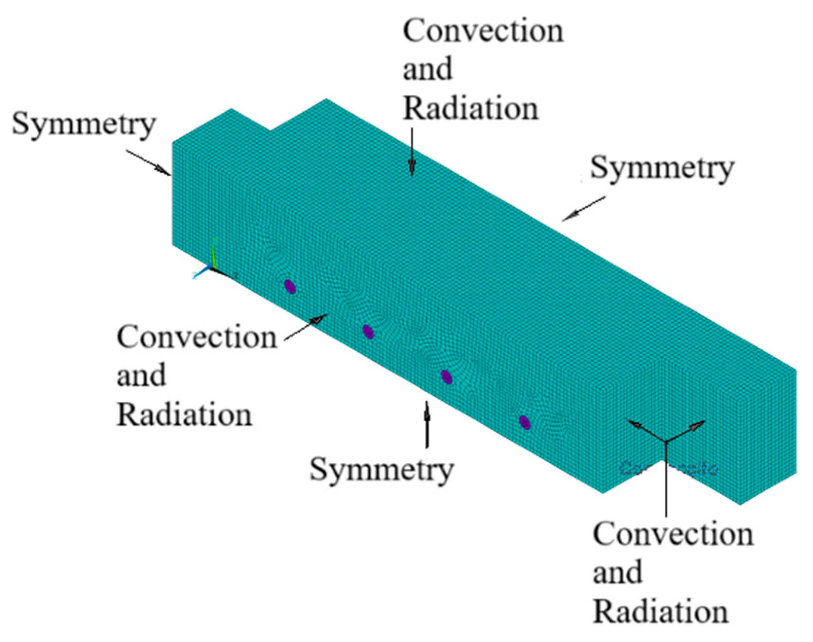
For the finite element meshes of the connections, the edge length of each element was set to 6 mm, based on the minimum size permitted in the model with gypsum plasterboard
Figure 8b). In
Figure 8c, different nodal points are positioned to measure the temperature evolution. Finite element analysis comprises two distinct phases, as shown in the flowchart in
Figure 1. The first phase involves thermal analysis, where the connection model is created, the mesh is generated, and the connection is subjected to fire
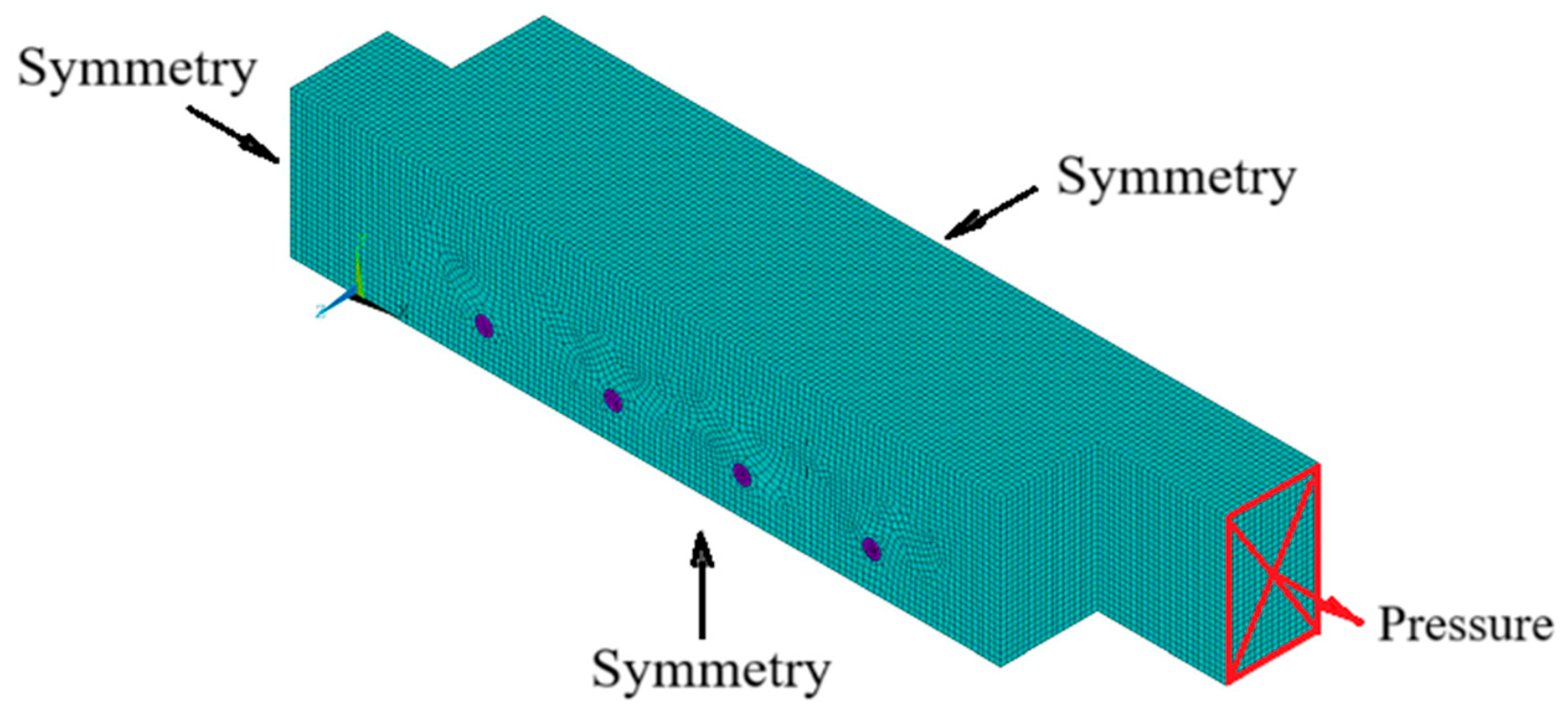
Figure 8b. In the second phase, using the same model, thermal loads are removed, and a mechanical load is applied at ambient temperature
Figure 8d. Then, using the same numerical model in
Figure 8d, a temperature field corresponding to a specific time of fire exposure is applied, enabling the thermo-mechanical study.
To analyse the behaviour of connections at high temperatures, it is necessary to determine the nodal temperatures at each moment in time. The effect of fire is reflected through the boundary conditions of convection and radiation applied to the connection surfaces, with the others being adiabatic, as shown in
Figure 8b. The imposed temperature-time curve corresponds to the standard ISO 834 fire nominal curve [
11]. The convection coefficient is 25 W/m
2K, and the emissivity is 1, according to Eurocode 1, part 1-2 [
14]. The initial temperature of the model is 20 °C. The finite element SOLID278 used has 8 nodes and 1 degree of freedom per node, which represents the temperature calculation. At this stage, contact between components is assumed to be perfect, with a continuous mesh at the interfaces. The analysis is performed in a transient state, with a time increment of 60 s, over a total duration of 3600 s. For the convergence criteria in the heat flux calculation, an absolute tolerance of 0.9 and a minimum reference value of 1 are considered.
Using the developed solution, a cross-section is selected at the level of two dowels to analyse heat transfer within the connection, as shown in
Figure 8c. Specific nodes are considered to track temperature changes: S1 on the non-fire-exposed surface, S2 outside the dowel, S3 inside the dowel, and S4 on the fire-exposed surface for the unprotected connection (Unp). In the protected connection (Pro), nodes G1, G2, G3, and G4 correspond to the same points.
4.1. Results of Thermal Analysis, Temperature Distribution
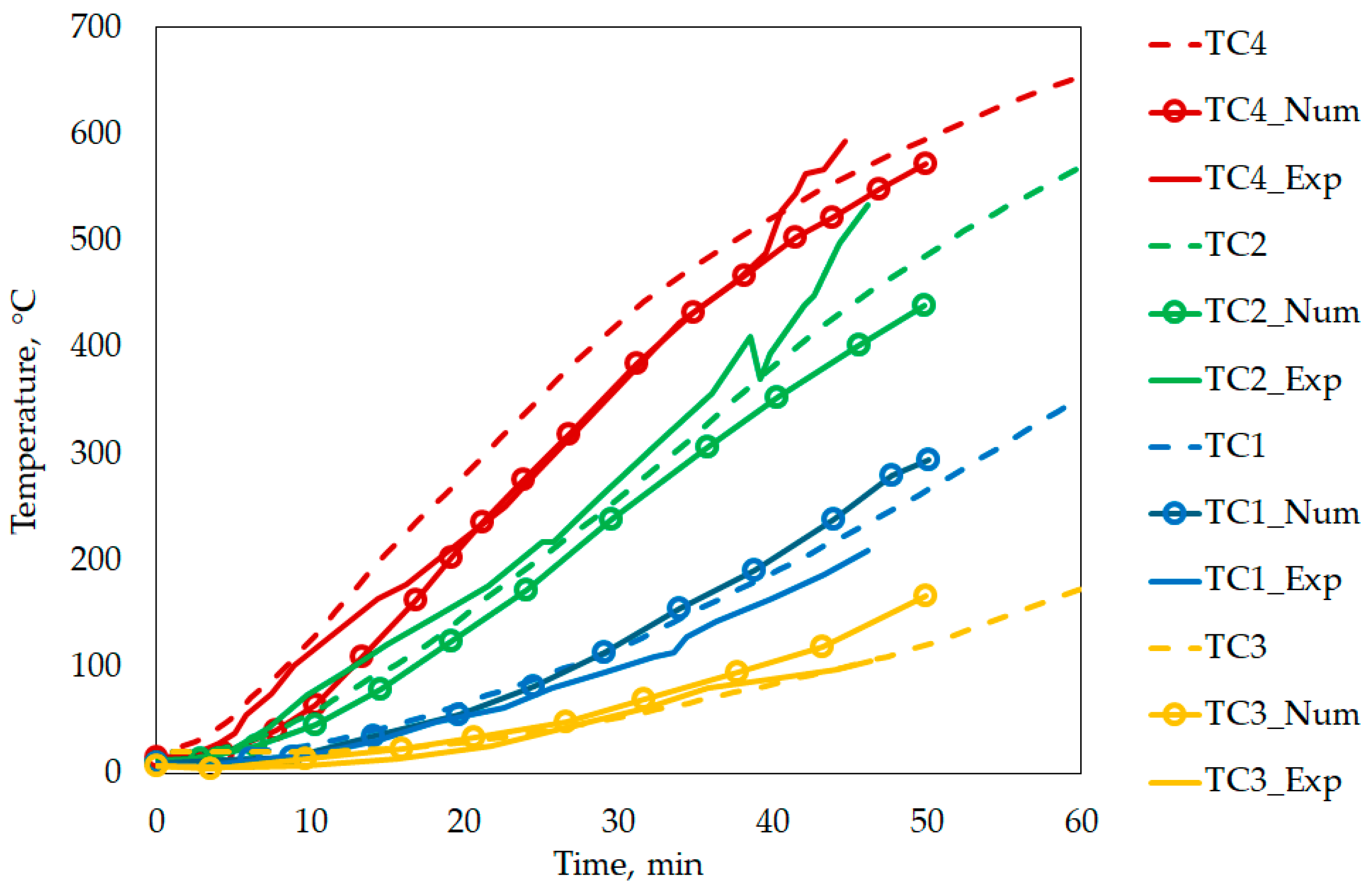
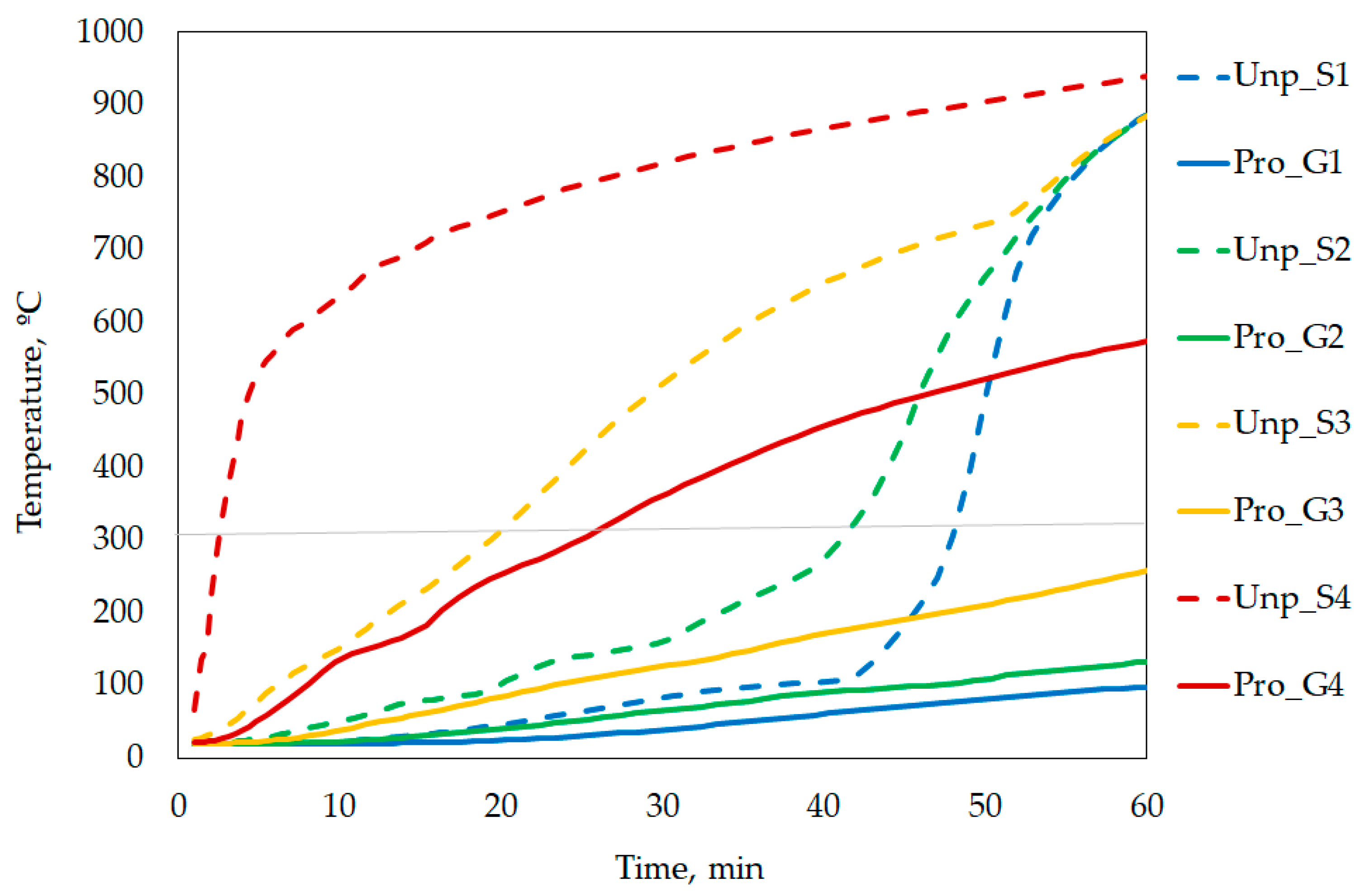
The graph of temperature evolution as a function of fire exposure is presented in
Figure 9.
As expected, inside the dowel (S3) increases in temperature significantly faster than the interior of the wood (S1 and S2), due to the high thermal conductivity of steel. This behaviour continues until approximately 35 min, when nodal points S1 and S2 experience an increase in temperature. After 55 min of fire exposure, S1, S2, and S3 show similar temperatures. Starting at 300 °C, the wood begins to char, resulting in the formation of an insulation layer on the surface, temporarily slowing the propagation of heat to the interior. This effect is visible in the more gradual temperature increase at S1 and S2. However, as the temperature increases, the thermal degradation of the wood intensifies, leading to cracking and progressive loss of material. This phenomenon results in a significant increase in thermal conductivity, especially after 500 °C, which explains the intense temperature rise observed after 35 min. At points located within the wood of the protected joint, G1 and G2, the temperature remains considerably lower over time, not reaching the charring rate temperature throughout the analysed fire exposure period. Up to approximately 35 min, a similar evolution is observed to that of the equivalent nodal points of the unprotected connection (S1 and S2). From this point on, there is a significant divergence, reflecting the effectiveness of the plasterboard protection, which helps maintain temperatures inside the wood lower level for considerably longer. In protected connections, the steel is not directly exposed to the effects of fire, which significantly reduces heat transfer inside the connection. This difference is evident when comparing points S3 and G3, located inside the dowel. The temperature evolution of point S4 is almost identical to the standard ISO 834 [
14] nominal fire curve, as it is located on the surface of the wood. In contrast, the temperature evolution of G4 shows a nearly linear increase over time; this behaviour can be explained by the constant thermal conductivity assumed for the gypsum plasterboard material.
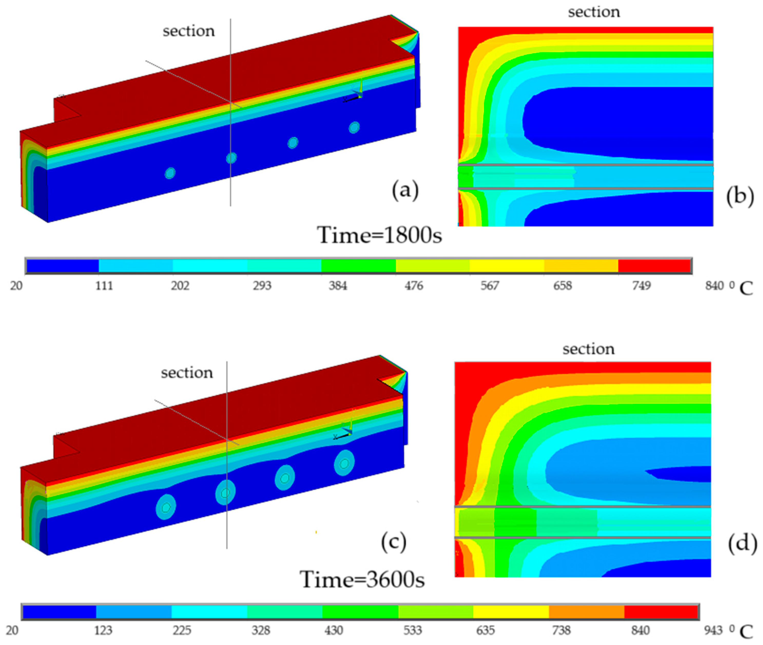
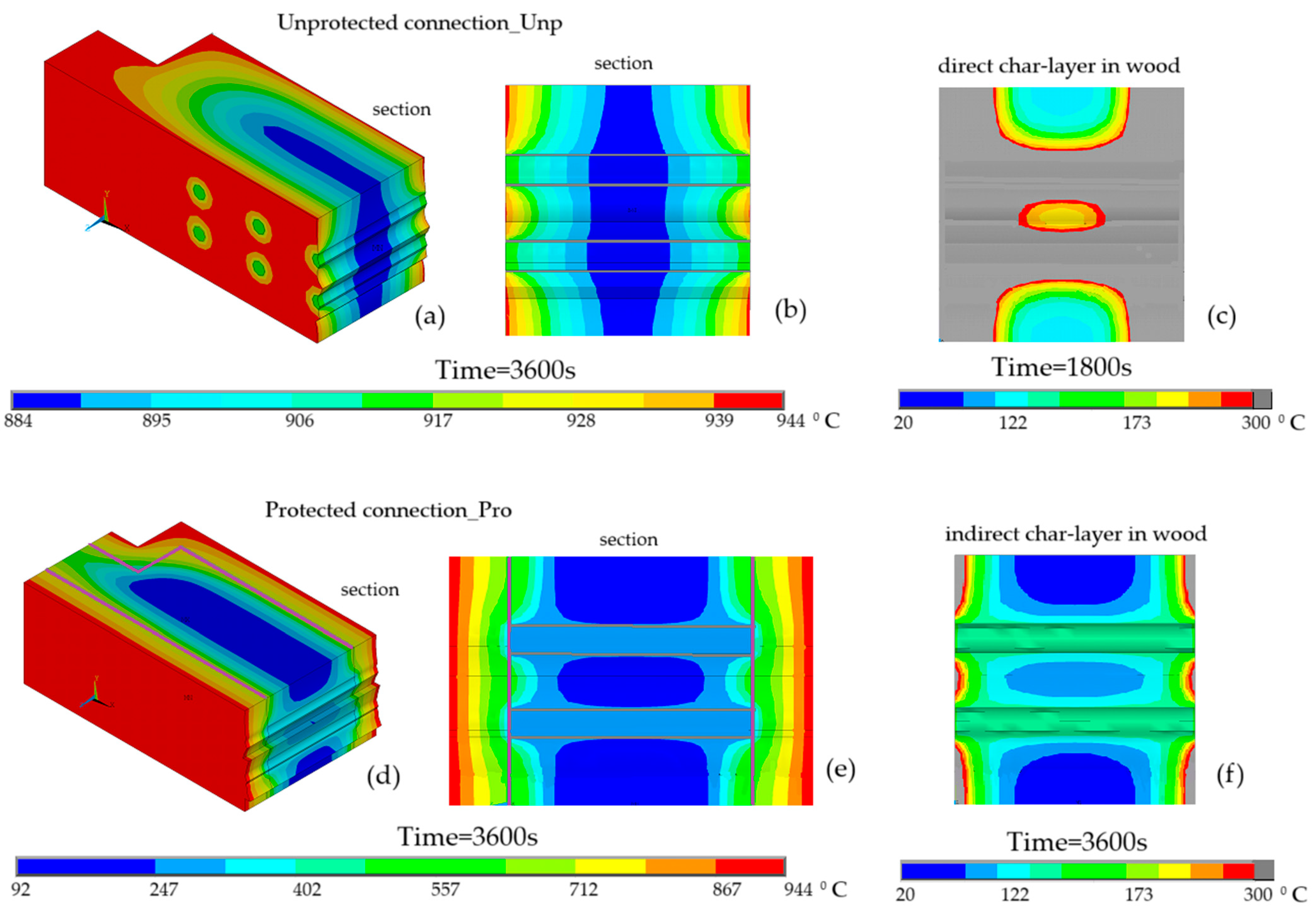
Figure 10 shows the temperature field in the protected and unprotected connections under fire exposure. In (a) part of the three-dimensional connection is presented, in (b) the cross-section with all materials considered in the study to better verify the temperature distribution, and in (c) the char layer in wood material at different time instants.
Significant differences are observed between the temperature gradients within the two connections. After 3600 s of fire exposure, the minimum temperature in the unprotected connection is 884 °C, indicating a complete char layer and complete loss of its mechanical strength, even at 1800 s, as shown. However, in the protected connection, the minimum temperature recorded is 92 °C, significantly lower. The maximum temperature recorded for both models is identical, equal to 944 °C. The temperature on the surface exposed to fire depends primarily on the temperature curve considered, the ISO 834 standard fire [
14]. This is not the case for materials with high thermal conductivity, such as steel, which rapidly transfers heat throughout the entire element.
Figure 10b for an unprotected connection, the steel dowel has 884 °C compared to the steel dowel in an unprotected connection with 247 °C.
The different results show that the temperature distribution among the steel elements is almost uniform, a behaviour expected given their high thermal conductivity. The wood elements display a more noticeable variation between the inner and outer zones, a difference that is even more evident in the gypsum elements. This variation in thermal distribution reflects the distinct heat conduction properties of each material, as well as how these properties change with increasing temperature. This behaviour highlights the effectiveness of gypsum as a passive fire protection material, as it greatly limits heat transfer into the connection.
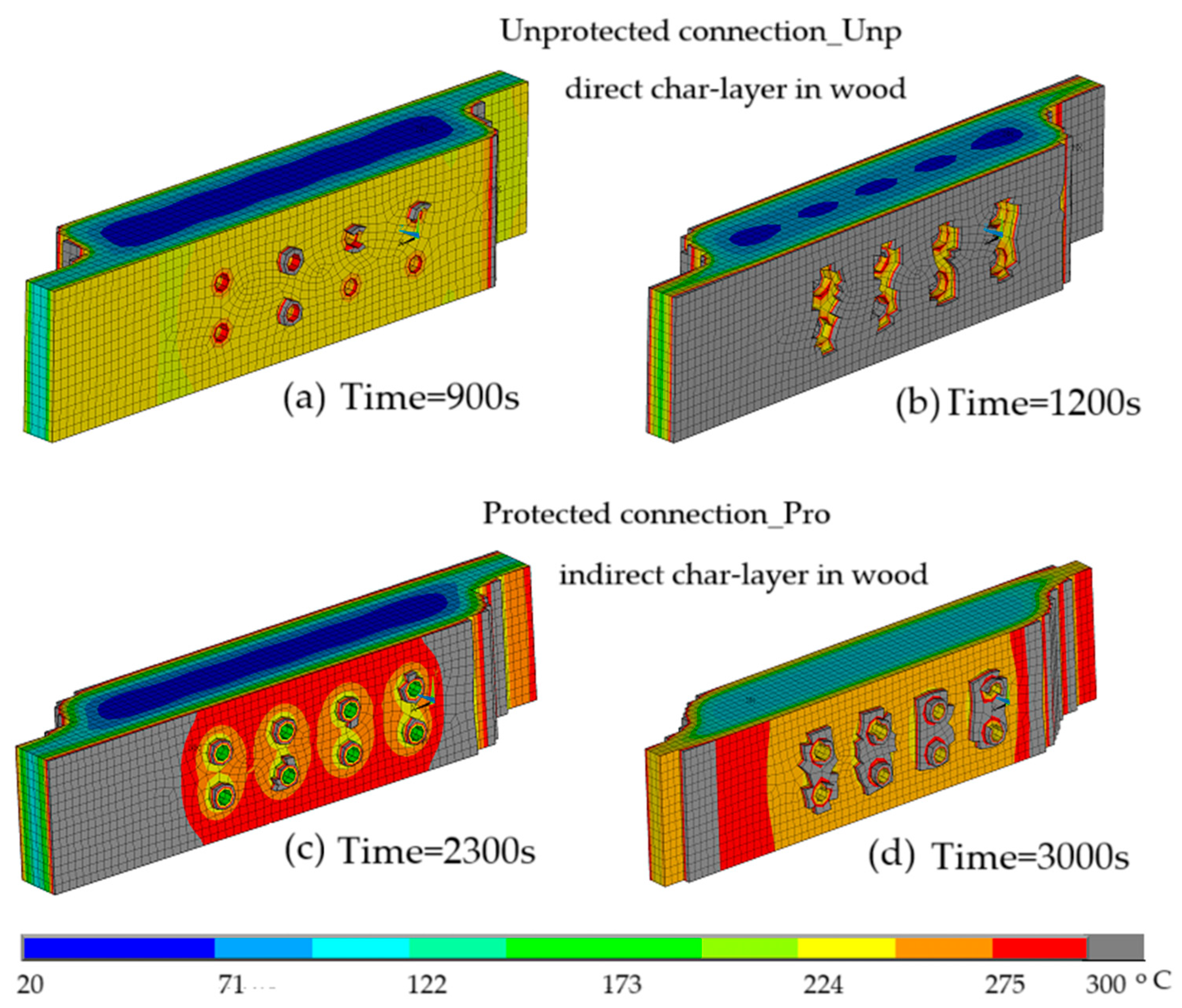
To visualise the char layer in the wood material (directly from fire in unprotected connection and indirectly for unprotected connection), different time instants are presented for each connection. In the protected connection, much of the wood thickness remains preserved at low temperatures, still presenting a significantly resistant cross-section. On the other hand, in the unprotected connection, the char layer has already compromised a substantial portion of the wood cross-section, resulting in a critical reduction in its resistance even at 1800 s. In the unprotected connection, all the wood around the dowels is charred, with a small amount of preserved wood remaining in the areas further away.
4.2. Results of Thermal Analysis, Char Layer Calculation
As previously shown, the unprotected connection is found to have considerably more charred volume than the protected connection.
To better evaluate the efficiency of the gypsum plasterboard protection, the direct charring rate was measured for the unprotected connections, with wood directly exposed to the fire action, and the indirect charring rate was measured for the protected connections, where the wood is not directly exposed to fire. The measurement was made in the cross-section shown in
Figure 10, in the direction normal to the plane of contact between the wood elements. The wood charred depth was measured at two different points, farthest from the dowels (p1) and midway between two dowels (p2), with three different measurements at different time instants. The results obtained are shown in
Table 3. For the unprotected connection, the resulting charring rate, for both points considered, is very close, but slightly higher than the values specified by Eurocode 5, part 1-2 [
12], where for Glulam under fire is equal to 0.65 mm/min. In the protected connection, the indirect charring rates are significantly lower, demonstrating the efficiency of the plasterboard in limiting thermal penetration and, consequently, in preserving the wood. Additionally, the effect of delaying the char layer between dowels, observed in
Figure 10c, is confirmed. For point p2, the measured charring rate is approximately 65% of that recorded at point p1, furthest of the dowels. Authors in [
17] measured the charring rate of a numerical model under the same conditions and with the same geometric characteristics, considering different instants and presenting a value of 0.69 mm/min, very close to the value obtained for the unprotected connection. In [
18], the charring rate was evaluated at different points in wood connections, considering the evolution of the char layer up to 900 s. Comparing the values for the same class of Glulam, but with 8 mm diameter dowels and a shorter distance between dowels, the charring rate for the point furthest from the dowels is very close to that obtained, 0.70 mm/min, while the value presented for the point between dowels is 0.43 mm/min, substantially lower. These results indicate that the initial thermal protection provided by dowels is more pronounced in geometries with smaller, more closely spaced connectors.
The results in
Table 3 indicate that, at the start of fire exposure, while the dowels are at a temperature below 300 °C, they help contain the local temperature, slowing down the charring of the nearby wood. However, once they surpass this temperature, they speed up the formation of the char layer in the surrounding wood. This behaviour has been noted in several studies examining connections with wood and steel elements. Metallic components, such as dowels, screws, and plates, tend to protect the wood in the early stages of fire exposure [
18,
19], but as the temperature rises, they become preferred pathways for heat transfer, leading to a faster development of the char layer within the connection [
20].
The loss of the load-bearing capacity is directly associated with the progression of charring rate, which leads to a reduction in the resistant area, as the charred material ceases to contribute structurally.
To highlight the evolution of the resistant cross-section over time,
Figure 11, presents the non-charred wood of the numerical models, hiding the elements whose temperature exceeds 300 °C, through the introduction of the APDL code. The results of the unprotected connection are observed in (a) for 900 s and (b) for 1200 s, of the protected connection in (c) for 2300 s and (d) for 3000 s.
As time progresses, the unprotected connection experiences a faster decrease in thickness, especially in the dowel area. At 900 s, some wood remains near the dowels, but by 1200 s, this area is much more damaged. In the protected connection, the insulation provided by the plasterboard slows down degradation in these zones, and even at 3000 s, some material is still visible around the dowels, despite a more developed char layer in the outer parts of the connection. The illustration in
Figure 11 confirms the earlier findings, highlighting the role of plasterboard in lowering the charring rate, particularly in the wood touching the dowels.
4.3. Results of Thermo-Mechanical Analysis
Thermo-mechanical analysis evaluates the load-bearing capacity of the connection at both room and high temperatures using the previously developed model. The finite element model employed is identical to that used in thermal analysis, but with the boundary conditions from the thermal analysis removed and the thermal finite element converted into a structural element. In this analysis, the SOLID185 finite element, featuring 8 nodes and 3 degrees of freedom per node, is utilised to calculate displacements along the x, y, and z axes. The contact surfaces between components, such as the wood elements and dowels, are also considered, employing contact-pair finite elements TARGE170 and CONTA174, with a friction coefficient of 0.3.
An incremental tensile load is incrementally applied to one end of the connection, and the opposite surface is considered fixed. To avoid possible bending effects of the connection, the z-displacements on the surface where the load is applied are kept zero. As can be seen in
Figure 8d for the unprotected and protected connections, the incremental pressure is only applied to the wood element. In the numerical model of the connection to obtain the behaviour during a given fire exposure, it is necessary to impose simultaneously the temperature field previously calculated in the nodal temperatures (file.rth).
4.4. Results of Thermo-Mechanical Analysis, Load-Bearing Capacity
In the first phase, the unprotected connection yield strength at room temperature was evaluated. Subsequently, the effect of adding gypsum board to the model under study was evaluated. The unprotected wood connection reached its yield strength at an applied pressure value of 17.88 MPa. In the protected connection, the maximum yield strength increased to 25.88 MPa.
Table 4 shows the results for the ultimate tensile strength of the wood connection, where
Nu,cg,Tamb and
Nu,cs,Tamb are the results obtained in the models under study, with and without protection, respectively, and
Nu,th,EC5 is the expected theoretical value, using the expressions from Eurocode 5, part 1-1 [
15]. Furthermore, the relative error about
Nu,cs,Tamb is presented.
As expected, due to the conservative nature of the Eurocode 5, part 1-1 calculation method [
8], the resulting mechanical strength of the developed numerical model is superior, presenting a relative error of approximately 25.5%. This difference is very close to that presented in the previously analysed study by M. Audebert et al. [
1]. The load resistance of the protected connection model is significantly higher, with a relative error of 44.74%. This increase is explained by the increased cross-section due to the thickness of the added gypsum board. Although gypsum has considerably lower mechanical strength than the other connection materials, its geometric contribution influences the overall result. It is also important to note that this reinforcement may depend on the method used to attach the gypsum board to the connection, as this directly affects the strength between the elements.
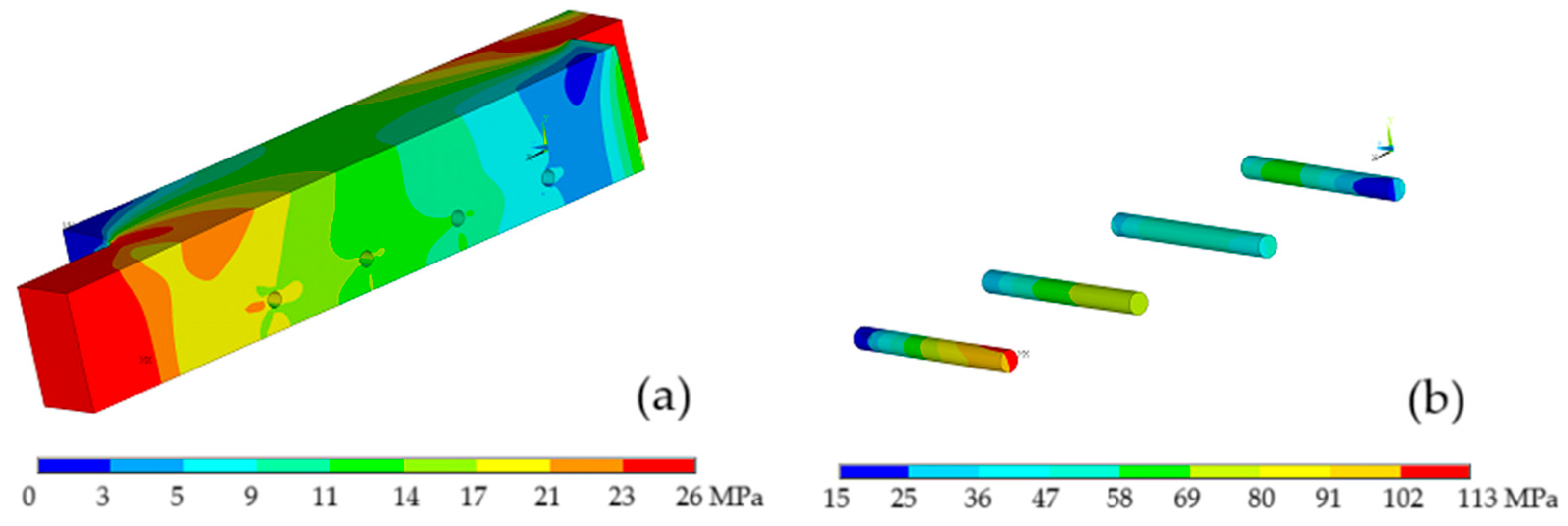
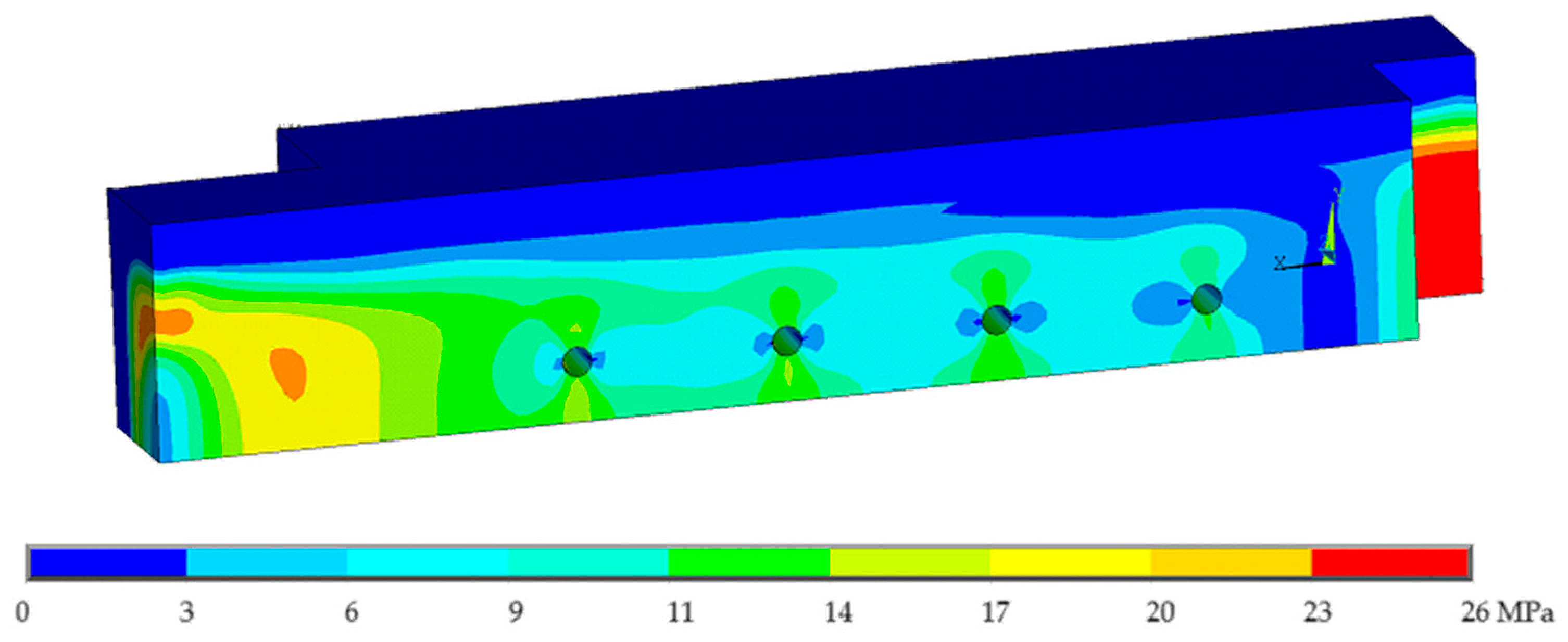
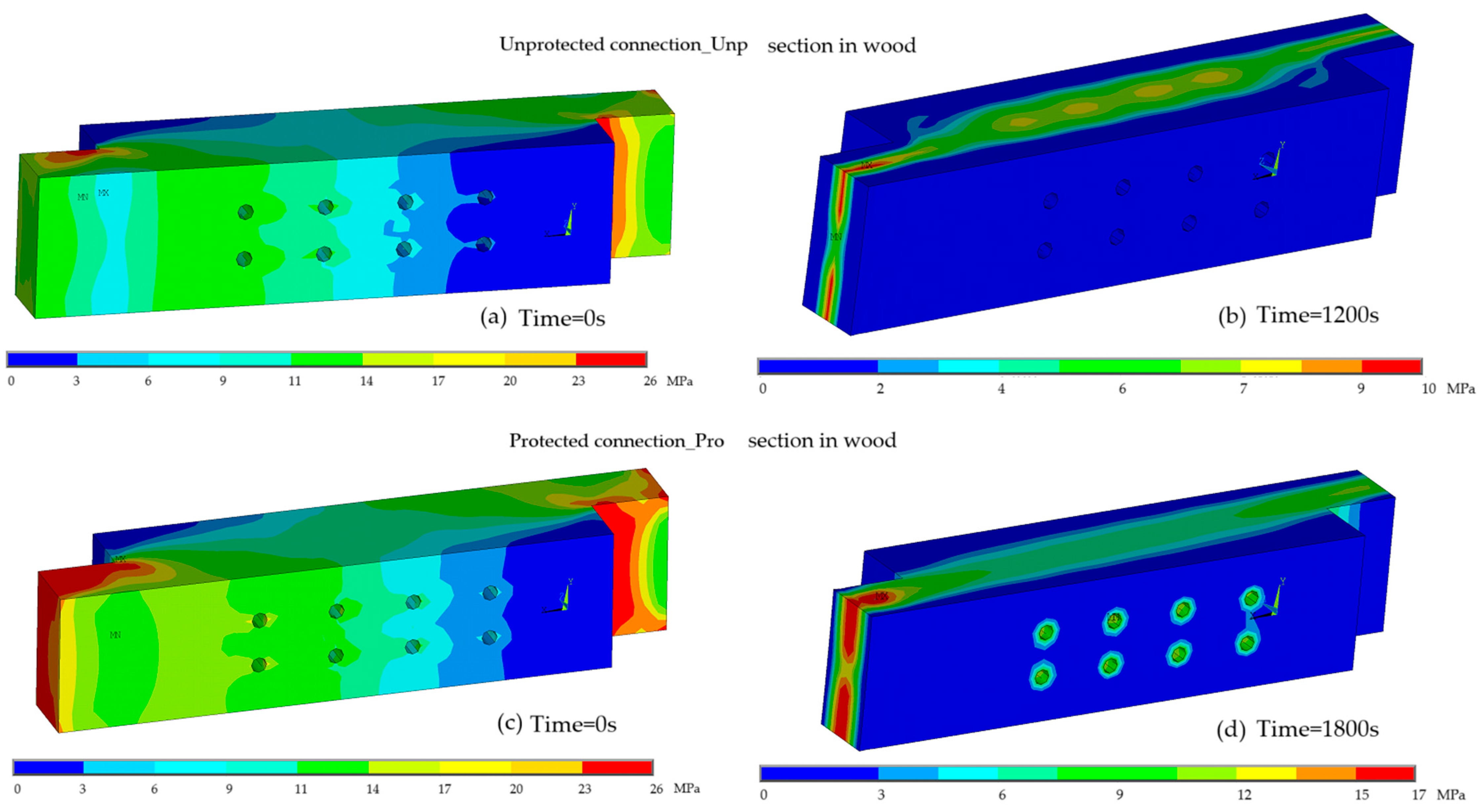
Figure 12 presents the equivalent von Mises stress for the unprotected and protected connections to the wood components, (a) at ambient temperature and (b) at high temperatures.
In both models, the damaged wood exhibited a maximum stress of 25.6 MPa in similar areas, close to the boundary conditions and stress concentration zones. For both models, a decrease in the maximum stress observed in the timber elements is observed, 10 MPa for the unprotected connection and 17 MPa for the protected connection in the areas where boundary conditions are applied. Along with the length of the elements, the charred volume of the timber presents zero stress. In the protected connection, in addition to the considerably higher maximum stress, it is observed that the timber elements have an installed stress level due to their ability to delay charring, thus maintaining a larger resistant area during longer fire exposure.
4.5. Simplified Equations for Load-Bearing Capacity Determination
In thermo-mechanical analysis, the load-bearing capacity of connections is evaluated at different times of fire exposure, aiming to quantify the decrease in mechanical strength over time and analyse the efficiency of the plasterboard protection.
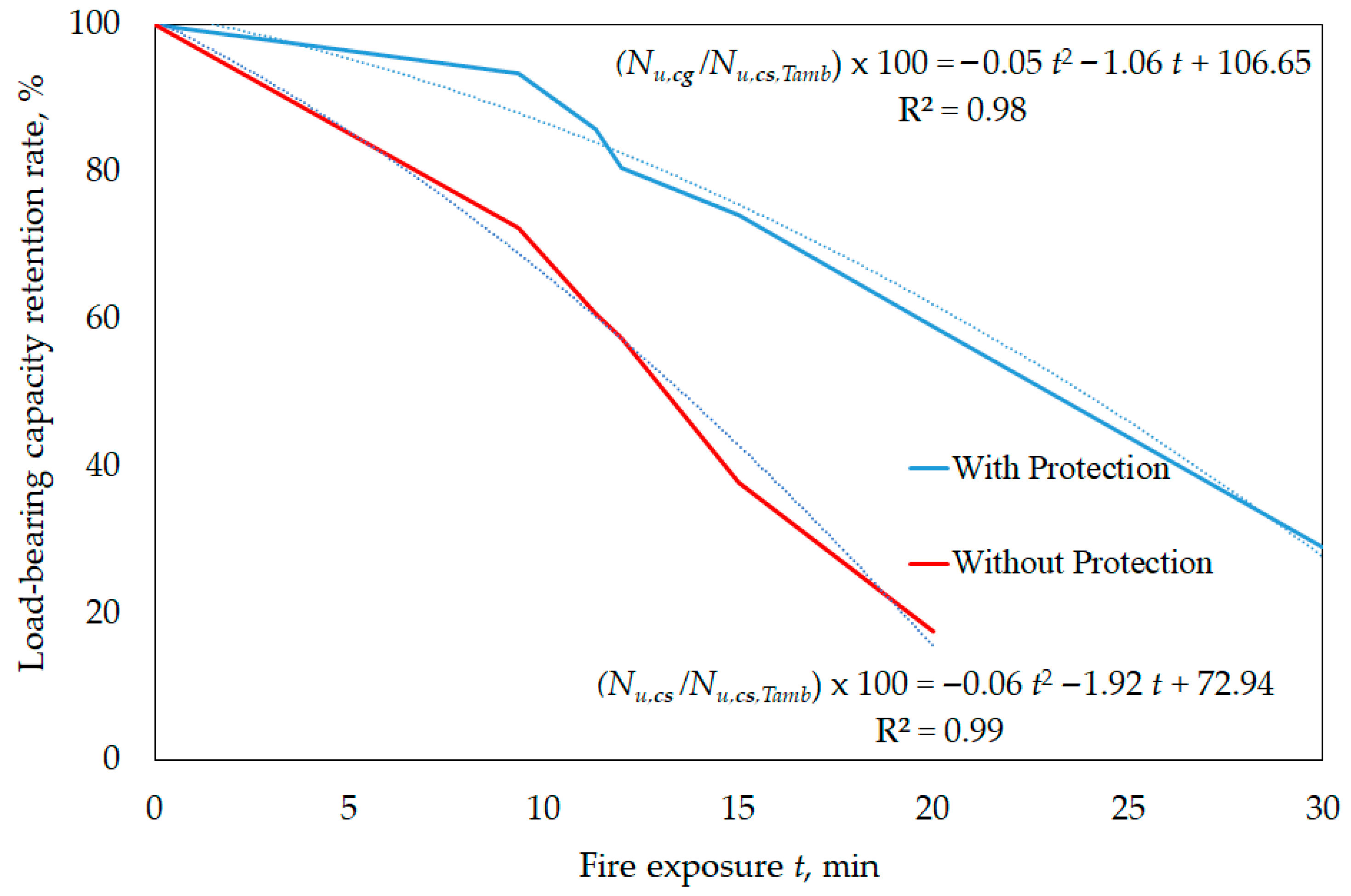
Figure 13 presents the results obtained, with second-degree polynomial trend curves. The corresponding equations are provided in the graph, allowing the prediction of the load-bearing capacity retention rate as a function of the fire exposure time. It is also observed that the square of Pearson’s correlation coefficient
R is very close to 1 in both cases, indicating a high degree of correlation between the results and the curves obtained.
For the unprotected connection, the load-bearing capacity retention rate was evaluated for the fire exposure times of 0 s, 560 s, 680 s, 720 s, 900 s, and 1200 s. In the case of the connection protected with gypsum boards, which maintains mechanical strength for longer, the analysis could be extended to 1800 s.
A clear trend toward superior performance is observed for the connection protected by gypsum boards, retaining its load-bearing capacity for substantially longer, especially in the initial phases of the fire. For the first time considered, 560 s, the unprotected connection has approximately 72% of its load-bearing capacity at room temperature, while the protected connection still retains 93%. As exposure time increases, the unprotected connection shows a progressively more pronounced reduction in load-bearing capacity, exhibiting only 17% of its original strength at 1200 s. From this point onward, there is a complete loss of mechanical strength. In contrast, although the protected connection begins to decline sharply after 560 s, it maintains significantly superior performance, preserving approximately 59% of its load-bearing capacity at 1200 s.
Between 560 s and 720 s, the load-bearing capacity of the protected connection decreases substantially, which may be due to the degradation of the gypsum mechanical properties. After 900 s, although the gypsum no longer performs a relevant structural function, it continues to play an important role as a thermal wall, slowing the propagation of heat and, consequently, the loss of strength inside the connection.
Overall, it is confirmed that the protected connection exhibits more gradual degradation, taking considerably longer to fully lose its mechanical strength when exposed to fire than the unprotected connection. The results obtained reinforce the efficacy of gypsum as a passive fire protection material.
According to Eurocode 5, part 1-2 [
12], the fire resistance time for an unprotected connection with dowels is 20 min (1200 s). In the fire test of the connections, according to the simplified method, the connection is tested for a load of 12 kN, corresponding to the result of the design actions in the fire exposure situation. According to the results of the thermo-mechanical analysis, for 1200 s of fire exposure, the connection tensile load is 12.66 kN, resulting in a safety factor of 1.05, considerably lower than that obtained through verification using Eurocode 5, part 1-2 [
12]. Furthermore, as seen in
Figure 12, the maximum stress supported by the connection now of failure is 10 MPa, much lower than the tensile strength under fire exposure, calculated using the simplified method, of 23.55 MPa.
This discrepancy may be because the wooden members of the connection under study have a thickness of 45 mm, the minimum value required by Eurocode 5, part 1-2 [
12] to achieve 20 min of fire resistance. As seen in the results of M. Audebert et al. [
1], connections with significantly thicker members show a slower reduction in load-bearing capacity over time.
P. Palma and A. Frangi [
21] conducted a study analysing the influence of different geometric parameters on the fire resistance of timber-steel joints. The authors demonstrated that the thickness of timber members stands out as a critical variable in the thermo-mechanical performance of connections. Increasing the thickness of timber members has a considerably greater impact on the fire resistance of the connection than other geometric factors considered, such as its height, connector spacing and diameter [
21].
The results highlight some of the limitations of Eurocode 5, part 1-2 [
12], whose resistance reduction factors are not dependent on relevant geometric variables, such as member thickness or connector configuration. However, as demonstrated, these factors can significantly influence the behaviour of connections under fire.
5. Conclusions
Thermo-mechanical analysis of dowelled timber connections in single shear under fire requires detailed modelling of char layer development and its impact on mechanical performance. Advanced numerical models, validated by experimental tests, are essential tools for reliable fire design and safety assessment. This work focused on studying simple-shear timber mechanical connections, with and without protection, subjected to fire. It presents a validated numerical approach, using finite element analysis, to assess the thermal and mechanical behaviour of wood connections under fire exposure.
In the case of passive protected connections, Eurocode 5, part 1-2 [
12], provides for a reduction in the charring rate with the addition of gypsum, based on the use of types A, H, and F gypsum boards. Their properties are still difficult to characterise, thus compromising the reliability of their application in specific design situations. However, the numerical models developed, based on the use of a type of gypsum board, demonstrated a significant reduction in heat transfer to the connection and a considerable delay in the initiation of the char layer, validating the effectiveness of the protection. The numerical models showed that the addition of protection can not only delay the thermal degradation of the connection but also contribute to an increase in the load-bearing capacity, particularly in the initial moments of exposure to fire. There was a more gradual degradation of the protected connection, maintaining the structural load-bearing capacity for a substantially longer period. This difference highlights the role of gypsum as a passive protection material and emphasises the need for sizing methodologies better suited to the characteristics of the materials used, as well as the variability of the construction configurations of wood connections.
With the numerical results obtained, two easy-to-use design equations are proposed, allowing the calculation of the load-bearing capacity in simple shear wooden connections, with or without protection, as a function of exposure to fire.
The research conducted is essential not only for a detailed understanding of connection behaviour but also for improving and updating technical design standards for fire safety, responding to the increasing use of wood as a structural material in sustainable solutions.
Based on the analysis conducted in this work, several areas are identified that require further research, both experimentally and numerically, to enhance the existing understanding of the behaviour of wood connections subjected to fire.
- -
One of the main limitations identified is the lack of data on the thermal and mechanical properties of gypsum boards listed in Eurocode 5, part 1-2 [
12]. These materials are recommended as passive protection solutions but remain unsuccessfully characterised, particularly in high-temperature environments. Future experiments, investigating these properties, as well as their evolution with temperature, could significantly contribute to improving current standards and their application in real projects.
- -
At the same time, an in-depth study of the different methods of attaching gypsum boards to connections is recommended. How the protection system is attached to the structural elements has a direct impact on stress transfer, the overall stiffness of the structure, and its thermal efficiency. Conducting experimental tests and simulations that evaluate the behaviour of different construction solutions, such as the use of mechanical connectors or adhesives, could provide essential data for developing more precise technical guidelines on the use of these solutions.
- -
Finally, conducting more comprehensive parametric studies, involving variations in wood types, element thicknesses, connector diameters and layouts, as well as different protection configurations, could offer a stronger basis for calibrating numerical and analytical models.

