Abstract
This study proposes a deflection-based criterion for the assessment of barrel support brackets to ensure the structural stability of large fire shutters installed in large-scale buildings such as logistics facilities. While the current extended application method in the BS EN 15269 standard allows for the evaluation of the structural adequacy of the barrel—primarily based on stress analysis—this research aims to establish a more reliable design guideline by additionally considering the deflection of barrel support brackets, which may become structurally vulnerable under high-temperature conditions. To achieve this, the bracket was modeled as a cantilever beam, and deflection equations were applied. The deflection and stress were analyzed for various rectangular hollow sections. Furthermore, the support capacities at ambient temperature and at 700 °C were compared, and regression analysis was conducted to assess the Accuracy and error rates associated with different deflection limits (L/180 to L/480). The results indicate that setting the deflection limit to L/180 yields the most favorable outcome in terms of structural safety and error minimization across most conditions. It is expected that the adoption of deflection criteria for barrel support brackets in the design of large fire shutters will contribute significantly to preventing the spread of fire and ensuring structural safety.
1. Introduction
In recent years, the demand for logistics facilities has significantly increased due to the rapid growth of e-commerce. In particular, with non-face-to-face consumption culture becoming more prevalent following the COVID-19 pandemic, the construction of large-scale logistics centers has accelerated. These logistics facilities contribute to improving the efficiency of supply chains by enabling the effective storage and distribution of goods [1].
However, due to their structural characteristics, logistics facilities entail substantial risks in the event of a fire. Most logistics facilities are designed with high ceilings and large open spaces, in which various types of combustible materials are densely stored. As a result, flashover can occur in a short period after ignition, increasing the potential for the fire to escalate into a large-scale disaster [2].
To mitigate these risks, both Active Fire Protection (AFP) and Passive Fire Protection (PFP) systems must be reinforced. Among PFP measures, fire shutters play a critical role in compartmentalizing large spaces and preventing the spread of fire. Nevertheless, at present, the evaluation criteria for fire shutters are not clearly defined, and in logistics facilities with high ceilings, there are additional difficulties in applying fire detectors. Therefore, there is an increasing demand for fire shutters with improved performance, and it is critical to establish performance evaluation methods that reflect the unique characteristics of logistics facilities [3,4,5].
Accordingly, this study investigates the characteristics of fire spread in logistics facilities and the importance of fire compartmentation to derive the specific features of fire shutters. A new calculation method is proposed by introducing a deflection limit approach into the extended application method for the assessment of large fire shutters. This approach is expected to enhance the structural safety of fire shutters and contribute to reducing fire damage in logistics facilities by reinforcing their compartmentalization.
The remainder of this paper is structured as follows: Section 2 describes the fire characteristics of logistics facilities, the importance of fire compartmentation, and the role of fire shutters in detail, including a review of the extended application methodology. In addition, it discusses potential issues that may arise during the extended application-based assessment of large fire shutters and proposes a new analytical approach to address these issues. Section 3 details the validation of the proposed deflection-based formula through a comparative analysis with the conventional extended application method, as well as the employment of regression analysis to verify the reliability of the proposed formula by applying optimal deflection limits. Section 4 discusses the results and limitations of this study. Finally, Section 5 summarizes the conclusions and contributions of this research.
2. Importance of Fire Compartmentation According to the Characteristics of Logistics Facilities and Problems with Existing Extended Application Methods
2.1. Fire Characteristics of Logistics Facilities and Performance of Fire Shutters
Logistics facilities are increasingly becoming larger and more complex, evolving beyond simple storage functions to include packaging and processing operations. In such facilities, rails are often installed to enhance internal logistics and work efficiency, and refrigeration or freezing systems are added when needing to distribute temperature-sensitive goods. As a result, certain fire compartmentation and protection standards have been relaxed. These logistics facilities typically have external walls that are vulnerable to fire and store large quantities of goods in rack systems. The densely packed goods on these racks increase the fire load and can lead to deep-seated fires, making the early detection and suppression of fires difficult [1,6].
As shown in Figure 1, logistics facilities are characterized by tall ceilings and high-density vertical storage using racks, which leads to a high fuel load within large interior spaces. This creates an environment that is vulnerable to fire and carries a high potential risk. Furthermore, the complex and enclosed structural layout of logistics facilities hinders firefighting and evacuation. In addition, polyurethane foam is commonly used as a cladding material, which can accelerate explosive combustion, generate large amounts of gas and residual vapors, and contribute to the occurrence of flashover and rapid flame spread [7,8,9,10].
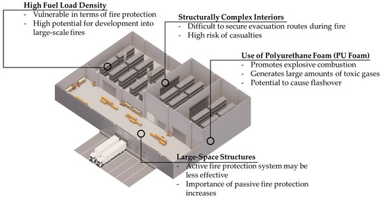
Figure 1.
Schematic overview and fire characteristics of typical logistics facilities.
According to statistical data from the National Fire Protection Association (NFPA), an average of 1450 fires in logistics facilities occurred annually in the United States between 2016 and 2020. Globally, fires in logistics facilities continue to occur consistently. Figure 2 illustrates the structural differences between logistics facilities and general buildings, including their large-volume centralized storage, tall ceilings with wide open spaces, large-scale installed equipment, and specific storage structures and configurations. To mitigate the fire risks inherent to logistics facilities, continuous research is being conducted to enhance relevant fire protection measures and fire safety performance [10,11,12,13,14].
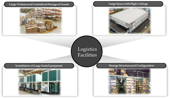
Figure 2.
Conceptual diagram illustrating the differences between logistics facilities and general buildings based on their spatial characteristics.
Fire safety standards can be broadly divided into those referring to Active Fire Protection (AFP) and Passive Fire Protection (PFP). AFP refers to systems such as sprinklers and detectors, which aim to suppress or control fire growth in the affected area. PFP, on the other hand, includes fire doors, fire shutters, and fire-resistant structural components, which are designed to prevent the transmission of flames, heat, and high-temperature gases between adjacent fire compartments. Both AFP and PFP are essential for ensuring fire safety in buildings, and optimal fire safety performance can only be achieved when both systems function effectively [15].
Due to the large spaces, high ceilings, and specific storage configurations of logistics facilities, it is often difficult to achieve optimal AFP performance. Therefore, it is necessary to further reinforce PFP measures. In logistics facilities, PFP elements such as fire doors, fire shutters, and firestop systems are typically used to establish fire compartments, among which fire shutters play a central role [16].
Fire shutters are fire protection devices that automatically close in response to heat and smoke during a fire, serving as an alternative to fire-rated walls when it is not feasible to install such walls. Fire shutters can be categorized into steel and fabric screen fire shutters, depending on the shutter curtain material. Before installation, fire shutters are tested for their fire resistance performance, typically using a vertical furnace. However, as a standard vertical furnace has a limited size of 3 m × 3 m, concerns regarding the reliability of performance evaluations for fire shutters that exceed this size have arisen [17].
As buildings with high ceilings and large interior volumes such as logistics facilities become more common, the use of large fire shutters is increasing. These larger shutters are expected to undergo greater deformation or performance degradation during fires compared to smaller shutters, highlighting the need for new evaluation and management approaches. However, due to limitations in furnace size, major fire resistance standards (BS 476-22, 1987; AS 1530, 1994; ISO 3008, 2007; ISO 834, 2017; NFPA 252, 2017; ASTM E-119, 2019; etc. [18,19,20,21,22,23]) only allow for scaled-down fire resistance tests at present, and full-scale performance evaluations have not yet been widely adopted [24].
Meanwhile, under the British and European standard BS EN 15269, the concept of extended application has been introduced. This method enables the performance evaluation of large fire shutters—scaled-up versions of the tested component—through engineering calculations based on fire resistance tests of smaller specimens, without conducting full-scale fire tests. BS EN standards distinguish between steel- and screen-type fire shutters, and for the latter, additional small-scale fire resistance testing is required. The detailed methodology is outlined in BS EN 15269-10 and BS EN 15269-11.
2.2. Issues in Performance Evaluation of Existing Large Fire Shutters and Proposal for Incorporating Deflection Criteria
In principle, the extended application outlined in BS EN 15269 involves evaluating the performance of large fire shutters by calculating the stress on structural members within the load path, based on the shutter box configuration supported by the building structure.
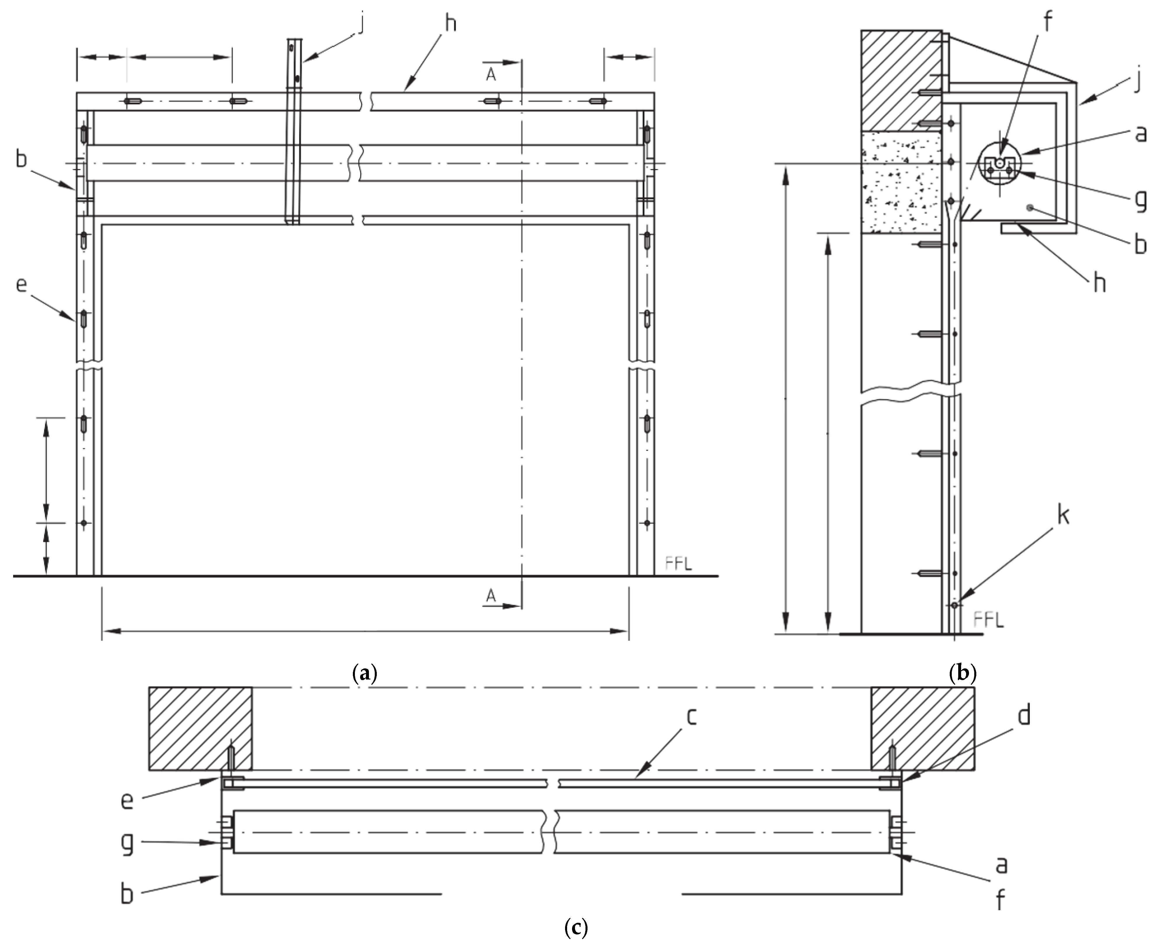
As illustrated in Figure 3 and detailed in Table 1, the barrel (a) located at the top of the fire shutter is responsible for unwinding the steel curtain during a fire event. Under normal conditions, the shutter curtain is rolled up around the barrel. When a fire occurs, the barrel rotates to lower the shutter curtain. The barrel is fixed to a shaft (f), which is supported by end plates (b). The shaft is driven by a motor, and the motor’s rotation is transmitted to the barrel. The shutter curtain, wound around the barrel, descends along guide rails that are fixed to the wall through guide fixing angles (e). The guide rails control the vertical movement of the curtain and must have sufficient depth and clearance to prevent the (steel or fabric) curtain from disengaging due to deformations caused by temperature changes or wind pressure. The barrel, shaft, and motor are collectively referred to as the upper assembly, which is supported by the barrel support bracket and the end plate bracket that are connected to the building structure.
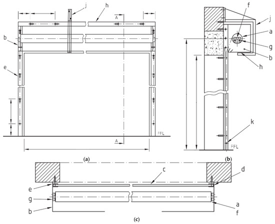
Figure 3.
Conceptual diagrams of a fire shutter: (a) front view; (b) side view; and (c) plan view.

Table 1.
Component of the fire shutter presented in Figure 3.
The structural load path of the fire shutter follows this sequence:
Shutter curtain → Barrel → Shaft → Shaft cup/support → End plate → End plate bracket → Building structure
The extended application method specified in BS EN 15269 enables the evaluation of the structural performance of large fire shutters by analyzing the stresses on each member within this load path, considering the configuration of the shutter box supported by the structure. Material properties such as the modulus of elasticity that are required for structural calculations must be determined based on the temperature conditions of the load-bearing components during the fire resistance test and in accordance with EN 1993-1-2. In the extended application method, it is generally assumed that the maximum stress experienced by the tested specimen during fire resistance testing defines the allowable limit stress for a large fire shutter.
Although BS EN 15269 provides methodologies for extending the application of fire shutters with different fire resistance durations, this study assumes a consistent fire resistance duration across all shutters [21,25,26,27].
For both steel- and screen-type fire shutters, stress values are fundamentally evaluated by considering the characteristics of the structural members within the load path. This evaluation generally involves the calculation of bending stress and deflection in the barrel, as well as an analysis of stress on the barrel support bracket, the shaft, and the end plate. For screen-type fire shutters, an additional test is required to account for the unique material properties of the screen fabric, which differentiates them from steel shutters.
In the analysis of the barrel’s stress and deformation, it is assumed that the weight of the shutter curtain is uniformly distributed along the barrel and that both ends of the barrel are simply supported. Under these assumptions, the bending stress (σB) in the barrel can be calculated using Equation (1), while the deflection (σB) can be derived using Equation (2):
In these equations, refers to the weight of the barrel assembly in Newtons (), while is the length of the barrel in millimeters (). The term represents the section modulus of the barrel (), while denotes the modulus of elasticity (), and is the moment of inertia of the barrel’s cross-section ().
By calculating the bending stress in the barrel, it becomes possible to evaluate the structural performance of large fire shutters under extended application conditions. The deflection value calculated from Equation (2) can also be used to assess whether the barrel’s sag would interfere with the shutter box case, thereby determining the necessity of installing such a case.
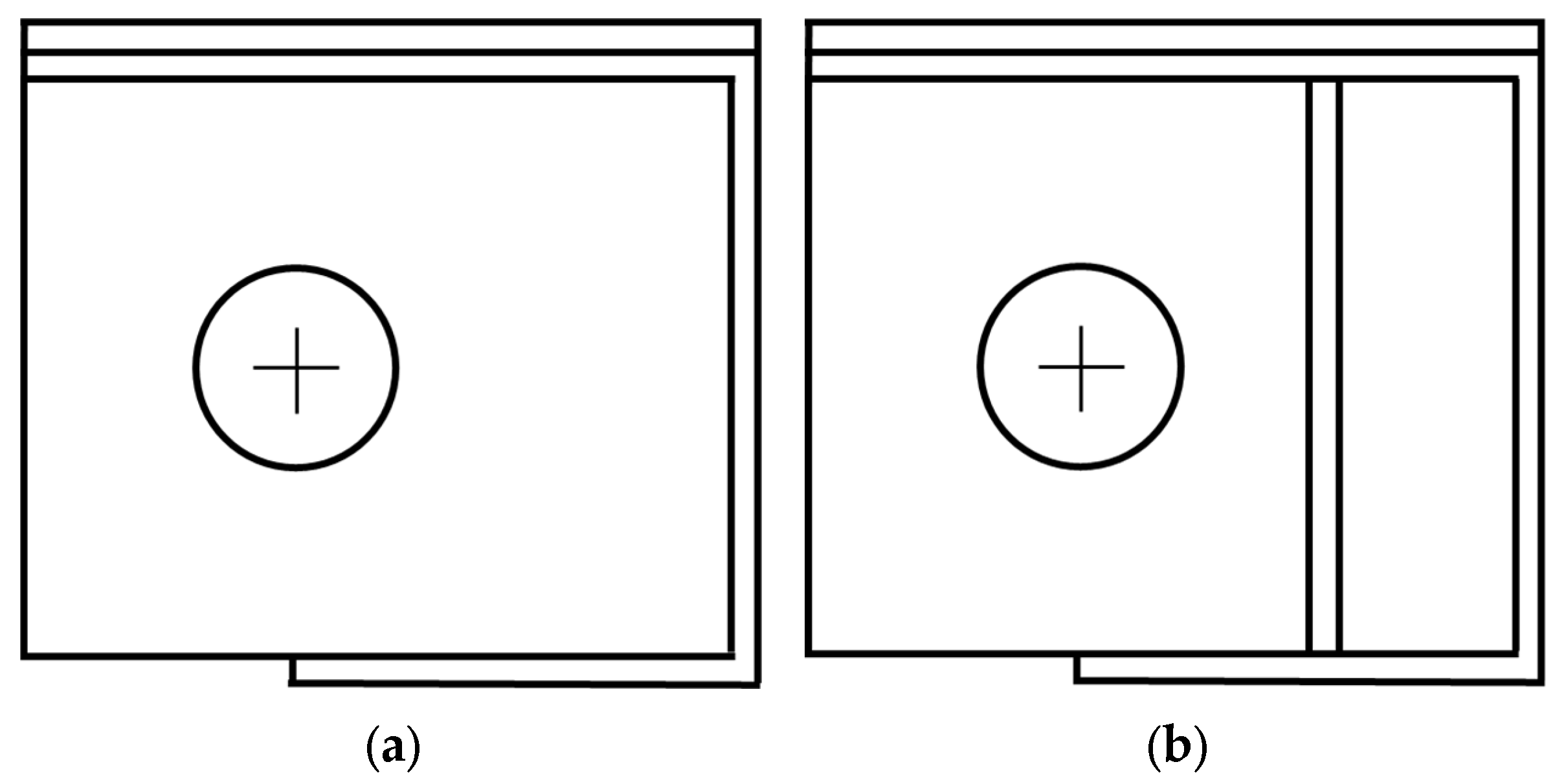
The barrel support bracket is an additional structural component designed to restrict the barrel’s deflection during a fire. In high-temperature environments where deflection of the shutter assembly is anticipated, the bracket provides support for both the barrel and the shutter box case, as illustrated in Figure 4.
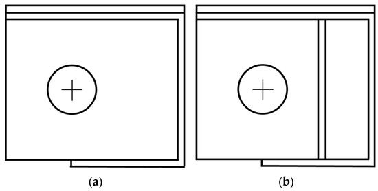
Figure 4.
Typical configurations of barrel support brackets: (a) barrel support bracket Type-1 and (b) barrel support bracket Type-2.
The barrel support bracket shown in Figure 4a represents the most basic form, while the reinforced type shown in Figure 4b is the most commonly used configuration. Both Type-1 and Type-2 brackets are commonly used configurations, typically comprising a basic shutter box case reinforced with additional rectangular hollow sections. Type-1 represents the standard configuration, while Type-2 may be selectively used at the discretion of the contractor. In the absence of a barrel support bracket, all loads are transferred directly to the structural wall through the end plate bracket.
When a single barrel support bracket is used, it must be capable of supporting at least 62.5% of the total weight of the barrel. If two support brackets are used, each must be able to support at least 31.25% of the barrel’s weight. A maximum of two barrel support brackets may be installed. In cases where only one bracket is used, it should be placed at the point of maximum barrel deflection. When two brackets are used, the distance between them must be at least 20% of the barrel’s length, and they should be symmetrically positioned on either side of the point of maximum deflection.
In the barrel support bracket calculation, the required support capacity Wr1, the imposed load Wr2, and the self-weight of the case hood Wr3 are determined using Equations (3)–(5), respectively. Subsequently, the total supportable load Wrtotal is computed using Equation (6), and the necessity of installing a barrel support bracket is assessed according to the criterion defined in Equation (7):
In these equations, is the moment of inertia of the barrel support bracket (mm4), is the maximum allowable stress of the bracket material (N/mm2), and n is the number of support brackets. The parameter a represents the distance from the shaft center to the fixed end of the bracket (mm), while y is the distance from the centroid of the bracket cross-section to the point of maximum stress (mm). The variable b denotes the length of the support bracket (mm), and is the cross-sectional area of the bracket (mm2). Additionally, is the case thickness (mm), and is the length of the case (mm).
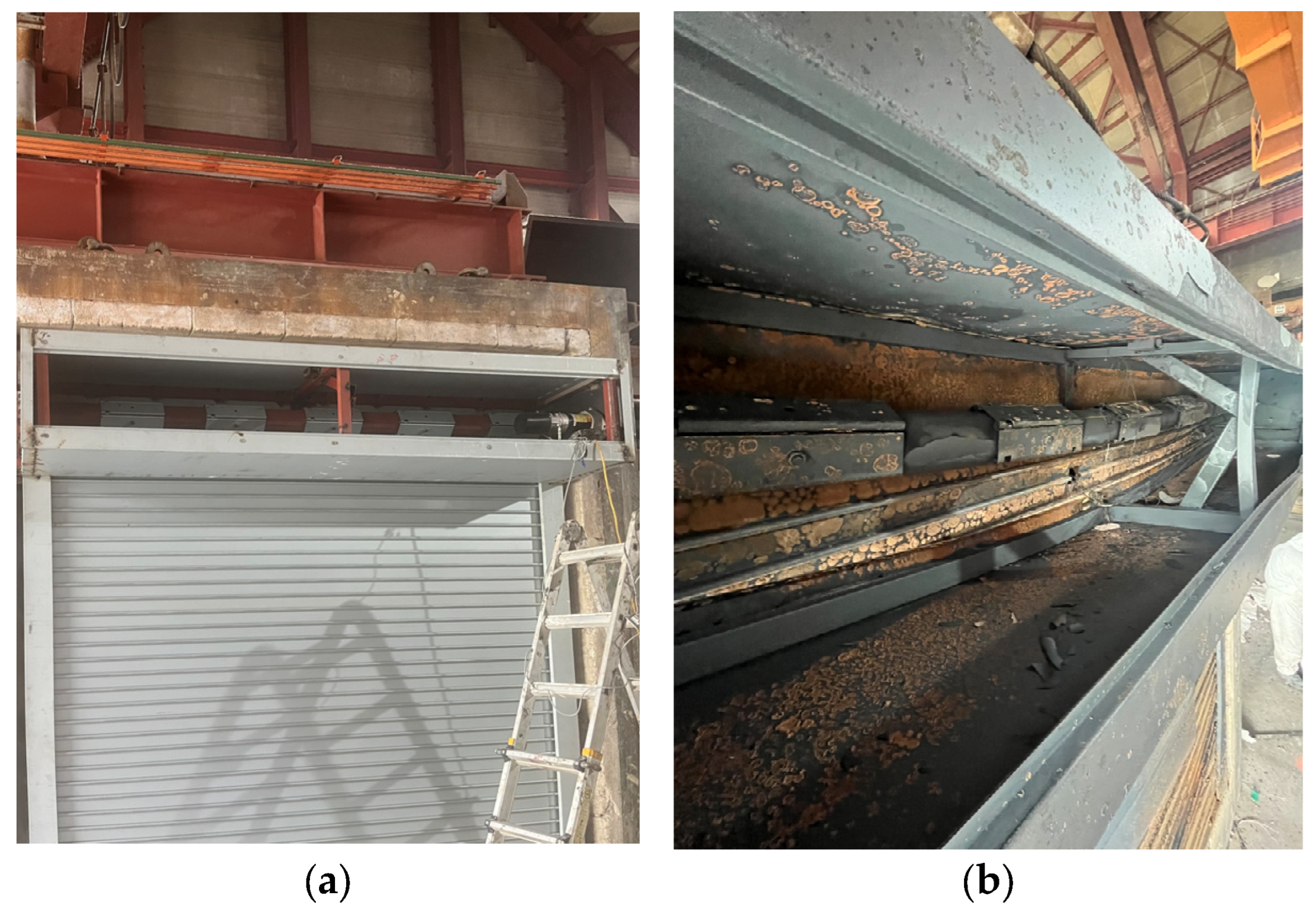
For standard-sized fire shutters, the deflection of the barrel is typically negligible, and the installation of a barrel support bracket is not essential. However, Figure 5a,b show the barrel and barrel support bracket of a fire shutter (3 m × 3 m in size) before and after a fire resistance test was conducted using a vertical furnace. As shown in Figure 5a, the barrel maintained a horizontally parallel position prior to the test, whereas, in Figure 5b, a noticeable vertical deflection of both the barrel and the bracket can be observed following a two-hour exposure during the fire resistance test. In shutters of this size, performance evaluations can be completed through direct fire resistance testing without the need for the extended application procedure. In contrast, for shutters with dimensions exceeding 10 m × 6 m, significantly greater stresses are introduced due to the larger surface area, and consideration of the elastic modulus of steel becomes increasingly important. The resulting barrel deflection also becomes more pronounced, thereby increasing the structural significance of the barrel support bracket in large-scale fire shutters.

Figure 5.
Fire resistance test of a 3 m × 3 m fire shutter: (a) condition of the barrel and barrel support bracket before the fire resistance test and (b) deflected condition of the barrel and barrel support bracket after the fire resistance test.
Like the barrel, the barrel support bracket is also made of steel and is susceptible to deflection under high-temperature conditions. Table 2 presents the strength reduction factors of steel according to temperature. While the modulus of elasticity remains at 1.000 at 20 °C and 100 °C, it significantly decreases to 0.130 at 700 °C, 0.070 at 800 °C, and 0.0675 at 900 °C. This confirms that the modulus of elasticity decreases as the temperature rises. A lower modulus of elasticity indicates greater vulnerability to deformation, a higher likelihood of sustained deflection, and minimal elastic recovery [28].
Table 2.
Linear elastic range and effective yield strength according to temperature.
Although the BS EN standards consider the stress and deflection of the barrel, they only account for the stress in the barrel support bracket—despite it being made of the same steel material—without imposing any specific limitation on deflection. The barrel support bracket plays a critical role in supporting the barrel under elevated temperatures and alleviating the load transfer to the end plate. In high-temperature fire scenarios such as those occurring in logistics facilities, fire shutters are primarily intended to form effective fire compartments. However, as the barrel deforms under heat, the central portion—namely, where deflection is the greatest—may develop an opening, thereby compromising the compartmentation function of the shutter.
Barrel support brackets, which are essential for preventing barrel collapse, exhibit varying deflection and stress values depending on the specifications of the rectangular steel tube used and the specific design of the bracket itself. Therefore, it is considered that by accounting for both deflection and stress based on the steel tube configuration used in the barrel support bracket, the structural integrity of the fire shutter can be preserved, and potential collapse can be effectively prevented.
2.3. Stress Analysis Incorporating Deflection Compared to the Conventional Calculation Method
Accordingly, this study compares numerical results obtained with the conventional formula used in BS EN 15269—which considers only the stress on the barrel—and a newly developed formula that incorporates deflection in order to ensure the structural safety of barrel support brackets, which play a critical role in fire shutters.
As illustrated in Figure 3, the barrel support bracket is fixed at one end and free at the other, redistributing the applied load to the fixed point. This configuration generates moment and stress, exhibiting the same structural behavior as a cantilever beam in structural engineering [29]. The deflection of a cantilever can be calculated using Equation (8):
where p is the applied load, L is the length of the cantilever, E is the modulus of elasticity of alloy steel, and I is the moment of inertia. In structural engineering, to ensure serviceability and safety, design limits are typically imposed on deflection (expressed in the form of L/n) [30].
Table 3 shows the deflection limits proposed by the International Code Council, where the allowable deflection ratios n are specified according to different structural conditions [31].
Table 3.
Deflection limits based on L, S or W, and D + L loads depending on construction type.
In general, deflection is limited by the inequality , and using Equation (8), the allowable load can be rearranged as . From this, the maximum allowable load is defined as .
Aligning this expression with the previously defined Equation (3), the final equation for the support capacity of the bracket, considering the deflection limit, is derived as Equation (9):
where , the modulus of elasticity, is a material-specific property of the steel tube used in the barrel support bracket and is subject to variation under elevated temperatures. The value of , the moment of inertia, differs depending on the cross-sectional geometry of the steel tube used in the bracket.
Therefore, the specifications of general structural rectangular hollow sections, as presented in Table 4, were used as a basis to calculate the stress and deflection of the barrel support bracket [32].
Table 4.
Area moment of inertia and section modulus according rectangular hollow section specification.
3. Comparison of Deflection by Bracket Type and Optimal Deflection Design Through Regression Analysis
As illustrated in Figure 3, the general configurations of barrel support brackets are classified into Type-1 and Type-2. The corresponding stress and deflection were analyzed based on the specifications of the steel tubes applied in each bracket type. The modulus of elasticity was distinguished and applied according to both ambient and fire conditions.
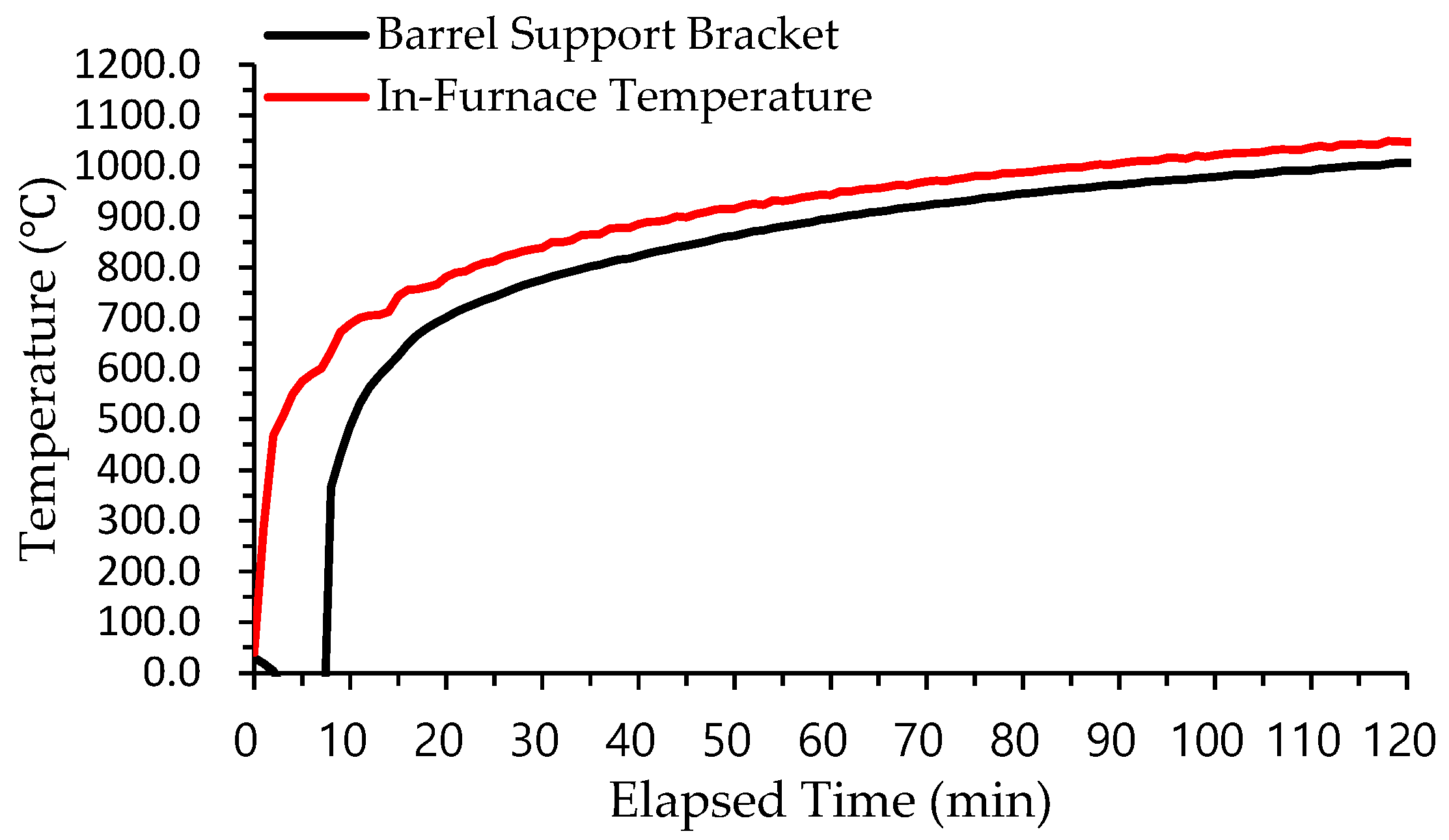
A fire resistance test using a vertical furnace was conducted to measure the temperature of the barrel support bracket and the internal temperature of the furnace. As shown in Figure 6, the furnace temperature increased to 1050 °C during the test, while the barrel support bracket experienced a peak temperature of approximately 980 °C. According to the BS EN guidelines, the modulus of elasticity should be applied based on the maximum temperature experienced by the structural member.

Figure 6.
Comparison of the barrel support bracket and furnace interior temperatures measured during a fire resistance test using a vertical furnace.
However, the objective of this study is to analyze the structural safety with consideration of the characteristics of the barrel support bracket. As shown in Table 2, once the temperature exceeds 700 °C, the linear elastic range becomes significantly reduced. Therefore, although it would be appropriate to apply the modulus of elasticity at 980 °C or 1000 °C according to the guidelines, this study applied 700 °C as the threshold temperature, considering it a critical condition in fire scenarios where the modulus of elasticity becomes negligible.
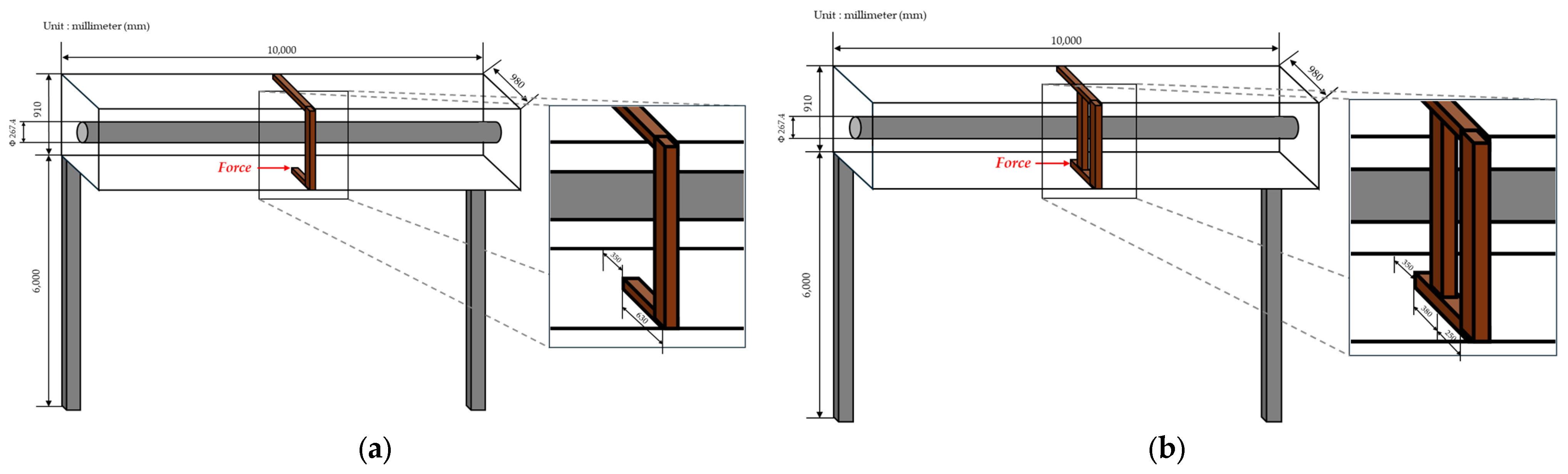
To compare the stress and deflection of the barrel support brackets, large fire shutters were modeled based on specifications typically applied in actual large-scale logistics facilities. Figure 7 shows the models used: (a) was modeled as Type-1 and (b) as Type-2. The weight of the barrel was estimated to be 20.11 kN.
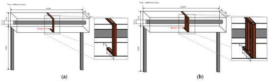
Figure 7.
Detailed specifications of large fire shutters by type: (a) barrel support bracket Type-1 and (b) barrel support bracket Type-2.
Based on expert consultation, a deflection limit of L/200 was initially applied, considering the long-term load-bearing characteristics of barrel support brackets. The modulus of elasticity at ambient temperature was taken as 205,000 , while at 700 °C, it was reduced to 26,650 .
3.1. Comparison of Stress and Deflection at Ambient Temperature and 700 °C in Type-1 Brackets
As shown in Table 4, specification numbers were assigned based on the x- and y-axis dimensions of the rectangular hollow sections used in the barrel support brackets. Using these specification numbers, the stress and deflection of the barrel support brackets were calculated based on Equations (3) and (9), and the results are presented in Figure 8a for ambient conditions and Figure 8b for fire conditions (700 °C).
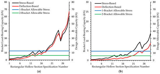
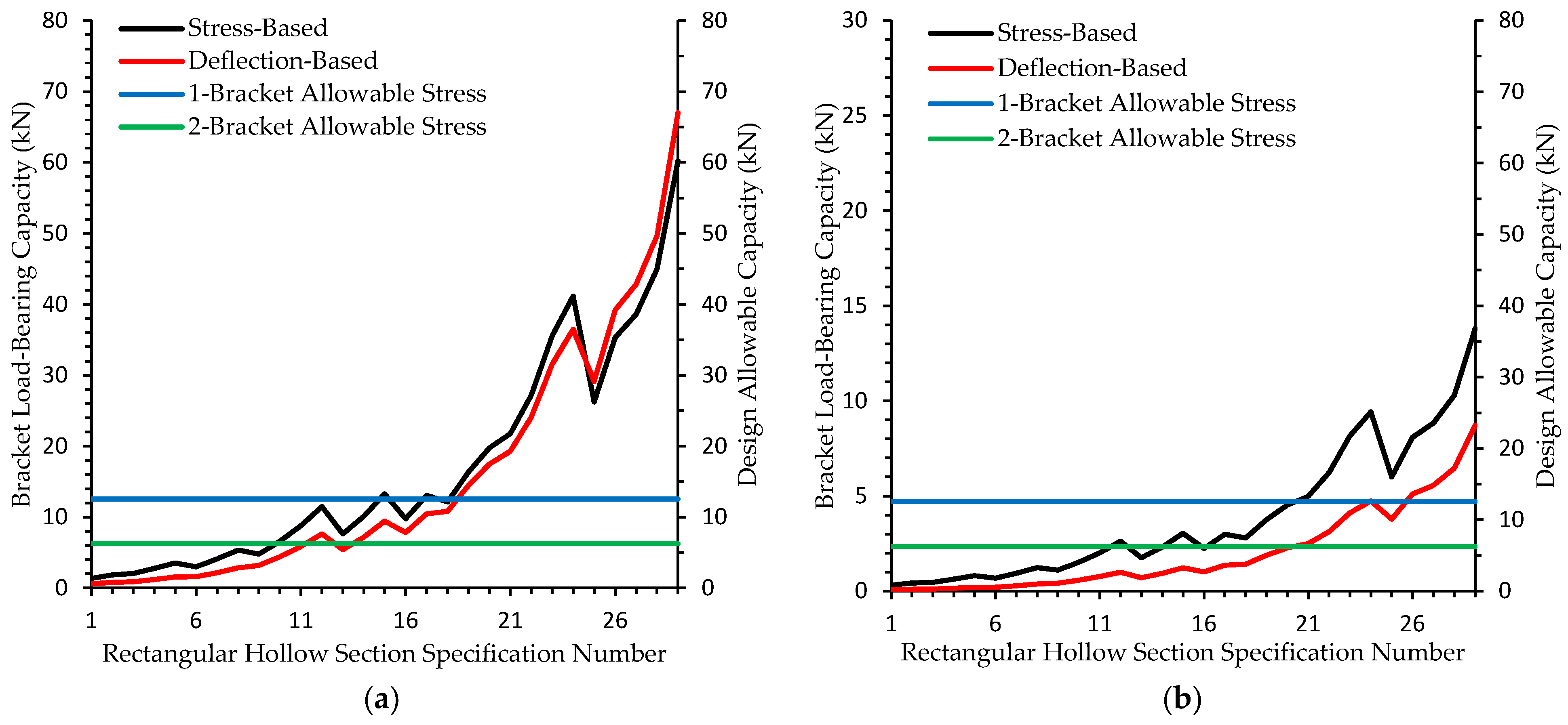
Figure 8.
Support capacity calculated based on stress and deflection: (a) Type-1 at ambient temperature and (b) Type-1 under fire conditions (700 °C).
In the case of the Type-1 bracket under ambient conditions, the stress and deflection values represent the limit load-bearing capacities of the barrel support brackets for each rectangular hollow section specification. The design allowable capacity was determined based on the BS EN guidelines, where 62.5% of the barrel assembly weight (20.11 kN) corresponds to 12.57 kN when one barrel support bracket is used and 31.25% (or 6.28 kN) when two brackets are used. These represent the structural limits that must be met by the bracket depending on the number of supports.
The current calculation method in BS EN 15269 considers only the load on the barrel when evaluating the barrel support brackets. As shown in Figure 8a, up to specification No. 24, the support capacity calculated considering deflection is smaller than that calculated based on stress. From specification No. 25 onward, the deflection-based capacity becomes greater than the stress-based capacity. This suggests that structural evaluations considering only stress for barrel support brackets could be potentially unsafe when deflection is not accounted for.
In Figure 8a, when one barrel support bracket is installed, specification No. 17—which presented a stress-based capacity of 13.05 kN—appears to be suitable. However, when deflection is also considered, at least specification No. 19 is required, for which the stress- and deflection-based load-bearing capacities were 16.36 kN and 14.48 kN, respectively— both exceeding 12.57 kN—and thus indicating structural safety.
When two barrel support brackets are installed, specification No. 10 appears adequate under the stress-only consideration, with a stress-based capacity of 6.63 kN. However, when deflection is also considered, at least specification No. 12 is required, with corresponding stress- and deflection-based load-bearing capacities of 11.48 kN and 7.63 kN, respectively; both exceed the required 6.28 kN and are therefore structurally safe.
In the case of Figure 8b, under fire conditions (700 °C), the maximum allowable support capacity per rectangular hollow section was 13.8 kN based on stress and 8.71 kN based on deflection. Compared to ambient conditions, the support capacity for specification No. 29 was significantly lower. At 700 °C, deflection-based support capacities were lower than stress-based ones for all specifications. This indicates that under fire conditions, deflection becomes a more critical factor in evaluating the structural safety of barrel support brackets.
Furthermore, for rectangular hollow section specifications No. 23 and No. 24, when two barrel support brackets are installed, the brackets appear structurally sound when only stress is considered; however, when deflection is taken into account, the brackets may not sufficiently support the barrel, indicating a risk of structural collapse.
At 700 °C, when only one barrel support bracket is used, no specification up to No. 29 can support 62.5% of the barrel’s weight based on the deflection capacity, making it essential to install two barrel support brackets. When two brackets are installed, structural stability is first secured from specifications No. 28 and No. 29.
These findings suggest that, under fire conditions, none of the rectangular hollow section specifications up to No. 29 can ensure structural stability with a single barrel support bracket when both stress and deflection are considered. This highlights the increasing importance of incorporating barrel support brackets in fire safety design practices.
3.2. Comparison of Stress and Deflection at Ambient Temperature and 700 °C in Type-2 Brackets
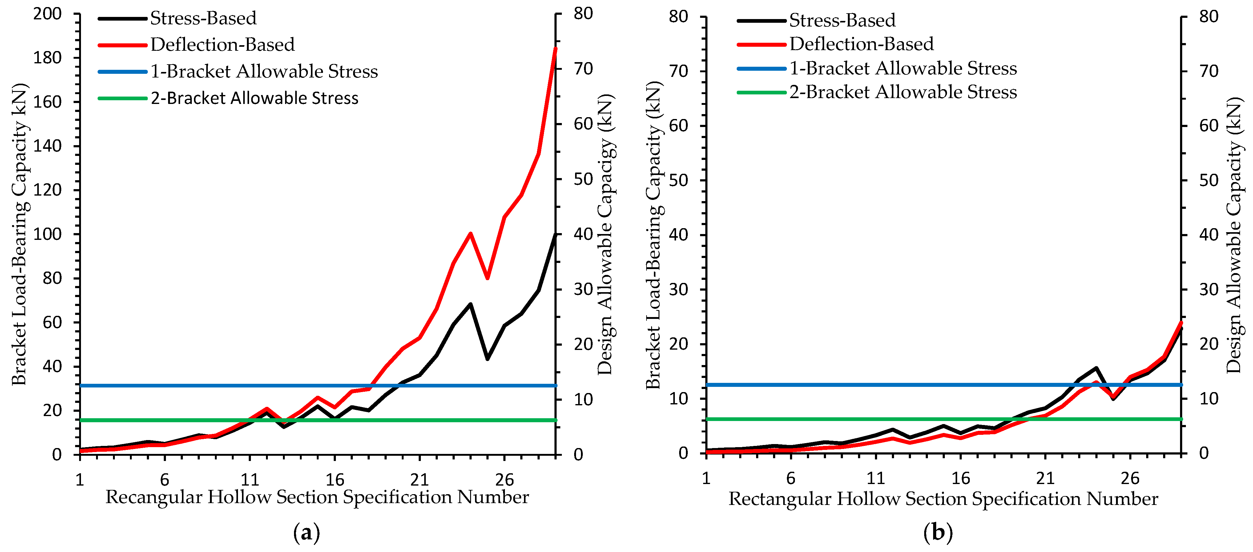
As detailed in Table 4, specification numbers were assigned based on the x- and y-axis dimensions of the rectangular hollow sections used in the barrel support brackets. For each specification, the stress and deflection of the brackets were calculated using Equations (3) and (9), with results presented under ambient conditions in Figure 9a and under fire conditions (700 °C) in Figure 9b.
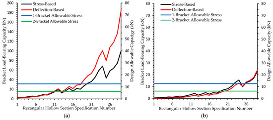
Figure 9.
Support capacity calculated based on stress and deflection: (a) Type-2 at ambient temperature and (b) Type-2 under fire conditions (700 °C).
In Figure 9a, when one barrel support bracket is installed, specification No. 11 appears structurally suitable when considering stress only, with a bracket load-bearing capacity of 14.54 kN. However, when deflection is considered, specification No. 10 (with a capacity of 12.56 kN) is deemed appropriate. When both stress and deflection are considered, specification No. 11 provides a stress-based capacity of 14.54 kN and a deflection-based capacity of 16.07 kN; both exceed the design allowable capacity of 12.57 kN, thereby indicating structural adequacy.
With the installation of two barrel support brackets, specification No. 7 satisfies the stress-based requirement with a capacity of 6.83 kN. However, specification No. 8—offering capacities of 8.90 kN based on stress and 7.85 kN based on deflection—exceeds the design threshold of 6.28 kN and can thus be regarded as structurally safe.
In the case of Figure 9b, under fire conditions (700 °C), when one barrel support bracket is installed, specification No. 23 appears sufficient based on stress only, with a load-bearing capacity of 13.52 kN. However, when deflection is considered, specification No. 24 (with a deflection-based capacity of 13.03 kN) is more appropriate. When both factors are considered, specification No. 24 provides a stress-based capacity of 15.63 kN and a deflection-based capacity of 13.03 kN; both exceed the required threshold of 12.57 kN, thereby indicating structural safety.
For configurations using two brackets, specification No. 20 appears adequate based on stress alone, with a capacity of 7.51 kN. When deflection is included, the minimum sufficient specification is No. 21, with stress and deflection capacities of 8.27 kN and 6.89 kN, respectively—both exceeding the required 6.28 kN threshold.
When comparing Figure 8a and Figure 9a, the highest bracket load-bearing capacities were observed in specification No. 29. For Type-1, the stress- and deflection-based capacities were 60.23 kN and 67.01 kN, respectively, while for Type-2, the corresponding values were 99.86 kN and 184.2 kN. Both the stress and deflection load-bearing capacities of Type-2 brackets exceeded those of Type-1 brackets, indicating that the former provide better structural safety.
3.3. Application of Optimal Deflection Limits Through Regression Analysis
As shown in Table 3, the allowable deflection limits vary from L/120 to L/360 depending on the characteristics of each structural member or environmental condition. In Section 3.2, a deflection limit of L/200 was applied to compare the support capacity calculated based on the conventional stress formula of the barrel support bracket.
The deflection limit of L/200 was established through expert consultation with a structural engineer, who advised that a limit of 1/200 is appropriate. To determine the optimal deflection limit for the barrel support bracket, regression analysis was conducted.
To evaluate the Accuracy of the deflection limits, this study employed the mean absolute error (MAE) and mean absolute percentage error (MAPE), which are defined according to the following formulas [33,34]:
Equation (10) represents the formula used to calculate the MAE. Applying this metric, the errors between the support capacities of barrel support brackets derived from stress-based calculations () and those from deflection-based calculations () can be quantitatively assessed.
The percentage error between these two values is expressed using the MAPE, as shown in Equation (11). Equation (12) defines the Accuracy, which serves as the inverse measure of the MAPE and indicates how closely the stress- and deflection-based load-bearing capacities align. For the purpose of proposing optimal deflection limits, was set as the load-bearing capacity calculated at deflection limits of L/180, L/200, L/240, L/360, and L/480. MAE, MAPE, and Accuracy values were calculated for each case under the following conditions: Type-1 at ambient temperature, Type-1 under fire conditions (700 °C), Type-2 at ambient temperature, and Type-2 under fire conditions (700 °C).
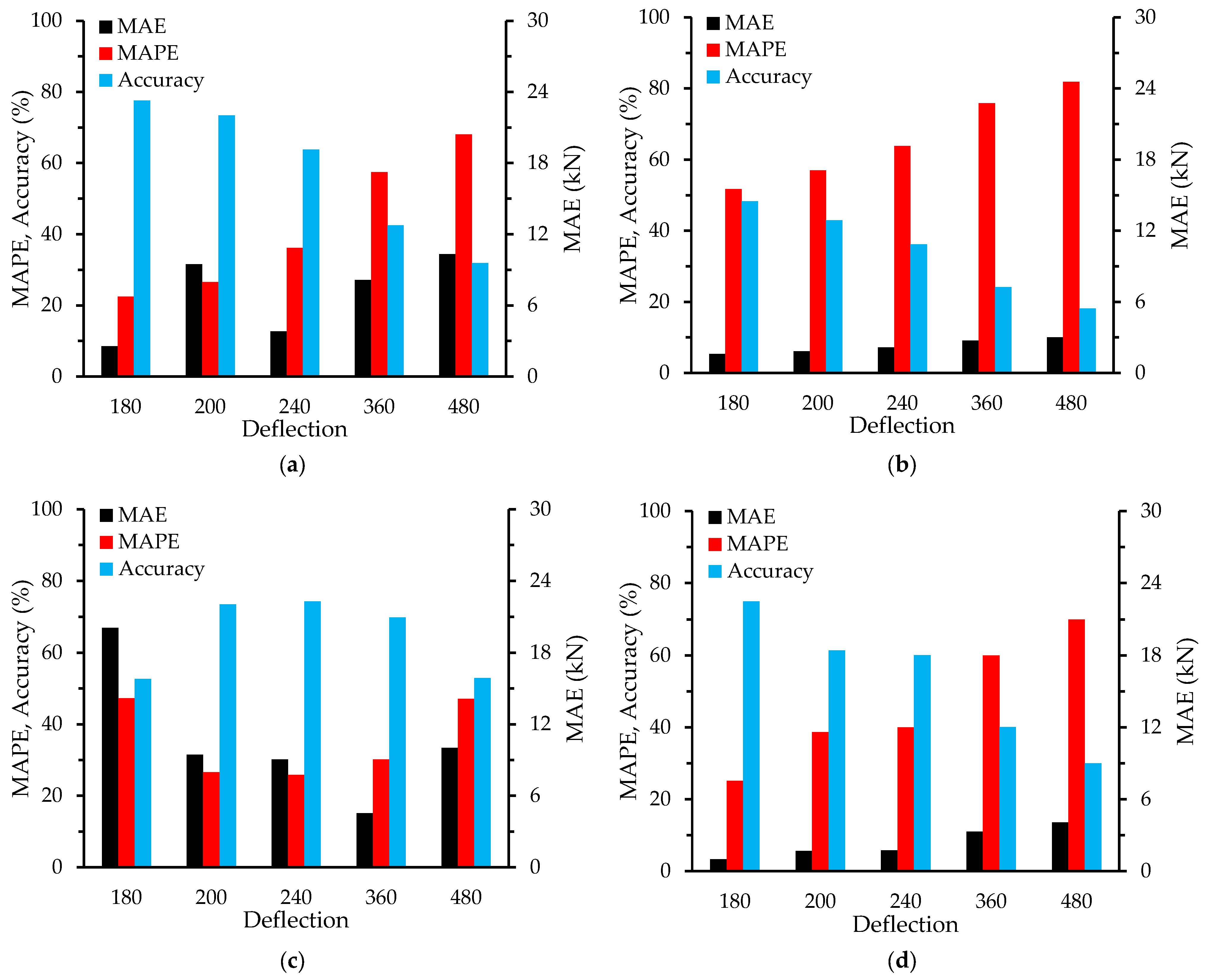
Figure 10a,b present the MAE, MAPE, and Accuracy values for Type-1 brackets, calculated under ambient temperature and 700 °C conditions, based on the modulus of elasticity corresponding to each temperature and various deflection limits—namely, L/180, L/200, L/240, L/360, and L/480. Meanwhile, Figure 10c,d illustrate the same parameters for Type-2 brackets using the respective modulus of elasticity values under ambient and high-temperature conditions.
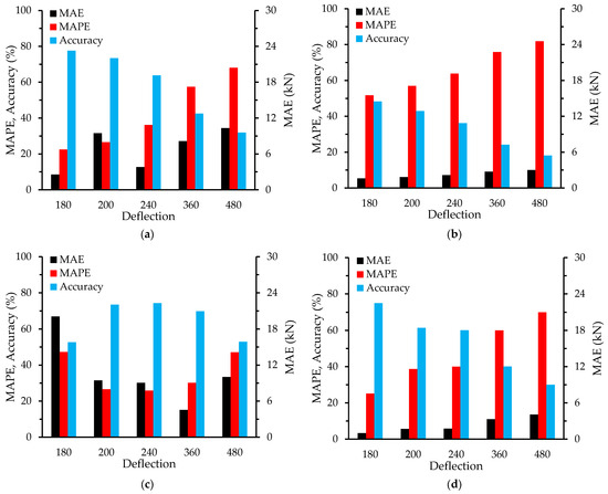
Figure 10.
MAE, MAPE, and Accuracy results for different deflection limits: (a) Type-1 at ambient temperature; (b) Type-1 at 700 °C; (c) Type-2 at ambient temperature; and (d) Type-2 at 700 °C.
In Figure 10a, under ambient temperature for Type-1, L/180 achieved an Accuracy of 77.576%, which is approximately 4% higher than that of L/200 (73.409%). In contrast, the Accuracy values for L/240, L/360, and L/480 were 63.816%, 42.544%, and 31.908 lower than the value for L/200, respectively. The MAPE increased sequentially from L/180 to L/480 as follows: 22.424%, 26.59%, 36.183%, 57.455%, and 68.091%. The MAE values were calculated as 2.556 kN (L/180), 9.457 kN (L/200), 3.81 kN (L/240), 8.151 kN (L/360), and 10.321 kN (L/480). These results confirm that under ambient conditions, L/180 offers superior performance in terms of MAE, MAPE, and Accuracy compared to L/200.
In Figure 10b, under fire conditions for Type-1, L/180 showed an Accuracy of 48.284%, which is approximately 7% higher than the 42.988% observed at L/200. Accuracy values for L/240, L/360, and L/480 were 36.213%, 24.142%, and 18.106%, respectively, and all were lower than the value for L/200. The MAPE values increased in the following order: 51.715% (L/180), 57.011% (L/200), 63.786% (L/240), 75.857% (L/360), and 81.893% (L/480). The corresponding MAE values were 1.599 kN, 1.821 kN, 2.163 kN, 2.727 kN, and 3.009 kN. Thus, under fire conditions, L/180 again proved to be superior to L/200 in terms of all evaluation metrics.
In Figure 10c, for Type-2 under ambient temperature, L/240 achieved the highest Accuracy at 74.196%, slightly outperforming L/200 at 73.409%. However, the Accuracy values for L/180, L/360, and L/480 were 47.312%, 30.175%, and 47.099%, respectively, and all were lower than the value for L/200. The MAPE values were 47.312%, 26.59%, 25.803%, 30.175%, and 47.099% for L/180 to L/480, and the MAE values were 20.068 kN, 9.457 kN, 9.05 kN, 4.53 kN, and 10.01 kN, respectively. These results suggest that, under ambient conditions, L/240 offers slightly better performance than L/200 for Type-2.
In Figure 10d, for Type-2 under fire conditions, L/180 achieved an Accuracy of 74.892%, which is over 13% higher than that for L/200 at 61.381%. Accuracy values for L/240, L/360, and L/480 were 60.037%, 40.025%, and 30.018%, all lower than the value for L/200. MAPE values increased from L/180 to L/480 as follows: 25.107%, 38.618%, 39.962%, 59.974%, and 69.981%. The corresponding MAE values were 0.994 kN, 1.681 kN, 1.74 kN, 3.291 kN, and 4.066 kN. Therefore, under fire conditions, L/180 outperformed L/200 in terms of MAE, MAPE, and Accuracy for Type-2.
Taken together, Figure 10a–d demonstrate that, compared to L/200, the L/180 deflection limit offers better performance in terms of MAE, MAPE, and Accuracy for all scenarios—except for Type-2 under ambient conditions, for which L/240 yielded slightly better results.
4. Discussion
This study empirically demonstrates the limitations of the current extended application methodology, which evaluates structural stability based solely on the stress of the barrel. While the existing BS EN 15269 standard focuses primarily on stress-based evaluations, this research quantitatively analyzes the impact of a significant reduction in modulus of elasticity and the consequently increased deflection at elevated temperatures on structural safety. The findings highlight the limitations of the existing criteria, which may underestimate structural risk and lead us to propose the inclusion of bracket deflection as an additional evaluation parameter.
The experimental and numerical analysis results revealed that deflection-based support capacity generally yields more conservative outcomes than stress-based methods. In particular, the Type-2 bracket demonstrated more stable load-bearing performance than the Type-1 bracket under both ambient and fire conditions (700 °C). This indicates that even a change in bracket geometry can enhance structural stability, and selecting appropriate geometries during the design stage is a critical factor in ensuring structural safety. Moreover, evaluating the deflection-based support capacity alongside stress-based capacity can provide a more comprehensive understanding of structural performance.
Regression analysis at various deflection limits—including L/180, L/200, L/240, L/360, and L/480—demonstrated that L/180 and L/200 were the most favorable. In particular, the L/180 limit exhibited higher predictive accuracy and lower error compared to L/200. These results suggest that L/180 may be the optimal deflection limit, while L/200 can be applied for more conservative designs. Given that current design standards may be overly lenient for structures such as large fire shutters that are expected to be exposed to high temperatures and heavy loads, adopting stricter deflection criteria in practical design is advisable. There is a clear need for structural design standards that comprehensively reflect real-world factors such as high-temperature exposure, long-term load application, and full-scale installation conditions. By applying optimal deflection limits, it becomes possible to conduct structural safety evaluations that are both conservative and realistically implementable.
This study was primarily based on numerical simulations and regression analysis. In the future, experimental validation under real-scale fire conditions is essential to verify the relationship between deflection behavior and structural stability. Additionally, iterative simulations using commercial structural analysis tools such as MIDAS should be conducted to enhance the applicability of the findings under various installation conditions and load scenarios. Ultimately, these efforts are expected to contribute to refining current EN standards and advancing the extended application methodology.
5. Conclusions
This study proposed the additional application of deflection-based evaluations for barrel support brackets in extended application assessments of large fire shutters, which are key Passive Fire Protection elements in large-scale buildings such as logistics facilities.
By examining the characteristics of logistics facilities, the fire behaviors specific to such buildings were analyzed, and a comparative review of Active and Passive Fire Protection systems was conducted. Among Passive Fire Protection systems, fire shutters were explored in depth, and performance evaluation methods under conditions where full-scale fire testing is not feasible were discussed; in particular, testing based on the extended application approach was conducted.
Within the extended application framework, it was proposed that the structural evaluation of barrel support brackets should include the deflection-based support capacity in addition to the stress-based assessment of the barrel. To compare the support capacities based on barrel stress and bracket deflection, the cantilever beam deflection equation was applied using the dimensions of the rectangular hollow sections used in the brackets.
A deflection limit of L/200 was initially adopted, and both ambient and elevated temperature (700 °C) conditions were assumed. Bracket types were categorized into Type-1 and Type-2, and the corresponding stress and deflection capacities were calculated and compared. For each case, suitable rectangular hollow section specifications that satisfy structural safety under fire conditions were identified. Unlike the conventional BS EN approach, which relies solely on stress-based evaluations, this study confirmed that incorporating deflection as an additional parameter can promote enhanced structural safety. Therefore, it is considered that including an assessment of deflection in the evaluation of barrel support brackets as part of the BS EN extended application method can facilitate improved safety assurance.
To propose an optimal deflection limit, regression analysis was conducted. MAE, MAPE, and Accuracy values were calculated under deflection limits of L/180, L/200, L/240, L/360, and L/480. The results indicate that deflection limits between L/180 and L/200 are the most appropriate.
These results demonstrate the validity of incorporating deflection-based support capacity when evaluating the structural performance of fire shutters in large-scale facilities through numerical calculations and regression analysis; however, further validation through multiple full-scale experimental tests is considered necessary. Therefore, based on this study, further research—both numerical and experimental—is suggested in order to ensure structural safety and improve the design criteria for fire shutters.
Author Contributions
Conceptualization, J.W.S. and H.S.; methodology, J.W.S. and H.S.; software, J.W.S.; validation, J.W.S.; formal analysis, H.S.; writing—original draft preparation, J.W.S.; writing—review and editing, J.W.S., D.K., S.H., S.L., S.J. and H.S.; supervision, H.S. All authors have read and agreed to the published version of the manuscript.
Funding
This work is supported by the Korea Agency for Infrastructure Technology Advancement (KAIA) grant funded by the Ministry of Land, Infrastructure and Transport (Grant RS-2022-00156237).
Data Availability Statement
All data generated or analyzed during this study are included in the published article.
Conflicts of Interest
The authors declare no conflicts of interest. The funders had no role in the design of the study; in the collection, analyses, or interpretation of data; in the writing of the manuscript; or in the decision to publish the results.
References
- Han, S.W. Characteristics & Fire Hazard Analysis of Logistics Warehouse and a Study on the Optimal Fire Detection Method—Focusing on the Air Sampling Detector. Master’s Thesis, Gachon University Graduate School of Industrial Environment, Seongnam, Republic of Korea, 2023. [Google Scholar]
- You, H.J. A Study on the Fire Risk Analysis and Fire Fighting System of Large Logistis Warehouse. Master’s Thesis, Gachon University Graduate School of Industrial Environment, Seongnam, Republic of Korea, 2020. [Google Scholar]
- Kim, B.H. A Study on the Application of the Fire Shutter Detector According to the Height of the Ceiling in Warehouse. Master’s Thesis, Seoul National University of Science and Technology, Seoul, Republic of Korea, 2018. [Google Scholar]
- National Fire Agency. Standard Guidelines for Performance-Based Design Assessment of Fire Protection Facilities: Causes and Safety Measures of Fire Accidents at Construction Sites; National Fire Agency: Seoul, Republic of Korea, 2023. [Google Scholar]
- Lee, S.B.; Seo, H.W.; Kim, D.H.; Lee, G.Y. Study on Fire Load and Duration of Fire in Logistics Facilities. J. Korea Soc. Hazard Mitig. 2023, 23, 177–185. [Google Scholar] [CrossRef]
- Jung, T.H.; Park, S.H.; Kim, H.K. A study on enhancing institutionalization on the fire analysis of the warehouse at Icheon City. In Proceedings of the 2008 Spring Annual Conference of the Korean Institute of Fire Science and Engineering, Daejeon, Republic of Korea, 24 April 2008; pp. 80–84. [Google Scholar]
- Kim, M.S. A Study on the Fire Simulation of Refrigerated Warehouse for the Analysis of the Relationship Between Oxygen Concentration and Fire Risk. Master’s Thesis, Gachon University, Seongnam, Republic of Korea, 2023. [Google Scholar]
- Lee, Y.W. A Study on Performance Criteria for Fire Compartment and Fire Door. Master’s Thesis, University of Korea, Seoul, Republic of Korea, 2017. [Google Scholar]
- Lee, J.G.; Min, S.H. A Study on the Operational Characteristics and Adaptability of Sprinkler Systems in Frozen Warehouses. J. Soc. Disaster Inf. 2025, 21, 300–309. [Google Scholar]
- An, B.K.; Kim, W.H.; Yang, S.J.; Ham, E.G. A study on the improvement of field activity for firemen in sandwich panel warehouse. J. Soc. Disaster Inf. 2020, 16, 421–429. [Google Scholar]
- Han, H.S. Methodology for Predicting Fire Growth Curves Using Combustibles Based on Fire Risk Classification of Commodities in Rack Storage Warehouse. Ph.D. Thesis, Daejeon University, Daejeon, Republic of Korea, 2025. [Google Scholar]
- Campbell, R. Warehouse Structure Fires; National Fire Protection Association NFPA, Research, Data and Analytics Division: Quincy, MA, USA, 2022. [Google Scholar]
- Nadile, L. The Problem with Big; National Fire Protection Association NFPA-192-Journal: Quincy, MA, USA, 2009. [Google Scholar]
- Harrington, J.L. Lessons Learned From Understanding Warehouse Fires. Fire Prot. Eng. 2006, 29, 22–28. [Google Scholar]
- Seo, H.W. A Study on the Standard Improvement of the Firestop System Installed in the Penetration Within the Fire Separating Element. Ph.D. Thesis, University of Seoul, Seoul, Republic of Korea, 2020. [Google Scholar]
- Lee, E.C. Case Analysis of Warehouse Fire by Fire Dynamic Simulation. Master’s Thesis, Chungbuk National University Graduate School of Industry, Cheongju, Republic of Korea, 2012. [Google Scholar]
- Ministry of Land, Infrastructure and Transport (MOLIT). Standards for Automatic Fire Shutters and Fire Doors, Article 2(2); MOLIT Notification No. 2019-592; Ministry of Land, Infrastructure and Transport: Sejong, Republic of Korea, 2019. [Google Scholar]
- BS 476-22:1987; Fire Tests on Building Materials and Structures—Part 22: Methods for Determination of the Fire Resistance of Non-Loadbearing Elements of Construction. BSI: London, UK, 1987.
- AS 1530.4:1994; Methods for Fire Tests on Building Materials, Components and Structures—Fire Resistance Tests of Elements of Building Construction. Standards Australia: Sydney, Australia, 1994.
- ISO 3008-1:2007; Fire Resistance Tests—Door and Shutter Assemblies—Part 1: General Requirements. ISO: Geneva, Switzerland, 2007.
- ISO 834-1:2017; Fire Resistance Tests—Elements of Building Construction—Part 1: General Requirements. ISO: Geneva, Switzerland, 2017.
- NFPA 252:2017; Standard Methods of Fire Tests of Door Assemblies. NFPA: Quincy, MA, USA, 2017.
- ASTM E119-19; Standard Test Methods for Fire Tests of Building Construction and Materials. ASTM: West Conshohocken, PA, USA, 2019.
- Woo, Y.J. A Suggested Method for Performance Evaluation of Large Scale Fireproof Shutters. J. Korea Soc. Hazard Mitig. 2020, 20, 111–116. [Google Scholar] [CrossRef]
- BS EN 15269-10; Extended Application of Test Results for Fire Resistance and/or Smoke Control for Door, Shutter and Openable Window Assemblies—Part 10: Fire Resistance for Steel Hinged and Pivoted Doorsets. BSI: London, UK, 2011.
- BS EN 15269-11; Extended Application of Test Results for Fire Resistance and/or Smoke Control for Door, Shutter and Openable Window Assemblies—Part 11: Fire Resistance for Rolling Shutters. BSI: London, UK, 2018.
- EN 1993-1-2; Eurocode 3: Design of Steel Structures—Part 1-2: General Rules—Structural Fire Design. CEN: Brussels, Belgium, 2005.
- Kim, S.Y.; Chu, D.S.; Lee, H.D.; Shin, K.J. Mechanical Properties of Structural Steel at Elevated Temperature. J. Korean Soc. Steel Constr. 2018, 30, 257–264. [Google Scholar] [CrossRef]
- Daw, T.A.; Daw, A.M. Stress and Deflection Analysis of Cantilever Mean by Numerically. Int. J. Inov. Sci. Res. Technol. 2020, 5, 718–721. [Google Scholar]
- Ministry of Land, Infrastructure and Transport (MOLIT). Standards of Structural Design for Buildings; MOLIT Notification No. 2016-317; Ministry of Land, Infrastructure and Transport: Sejong, Republic of Korea, 2016. [Google Scholar]
- International Code Council. International Building Code 2015; International Code Council: Country Club Hills, IL, USA, 2014. [Google Scholar]
- KS D 3568; Hot-Rolled Structural Rectangular Hollow Sections of Non-Alloy and Fine Grain Steels. Korean Agency for Technology and Standards: Eumseong, Republic of Korea, 2023.
- Lee, H.J.; Shon, J.G. Non-Integral AC Capacitor Voltage Calculation Method for Shunt Hybrid Active Power Filter. IEEE Access 2023, 11, 67968–67978. [Google Scholar] [CrossRef]
- Lee, J.W.; Park, K.J.; Cho, J.T.; Kim, J.Y.; Son, S.Y. Novel monitoring system for low-voltage DC distribution network using deep-learning-based disaggregation. IEEE Access 2020, 8, 185266–185275. [Google Scholar] [CrossRef]


Disclaimer/Publisher’s Note: The statements, opinions and data contained in all publications are solely those of the individual author(s) and contributor(s) and not of MDPI and/or the editor(s). MDPI and/or the editor(s) disclaim responsibility for any injury to people or property resulting from any ideas, methods, instructions or products referred to in the content. |
© 2025 by the authors. Licensee MDPI, Basel, Switzerland. This article is an open access article distributed under the terms and conditions of the Creative Commons Attribution (CC BY) license (https://creativecommons.org/licenses/by/4.0/).