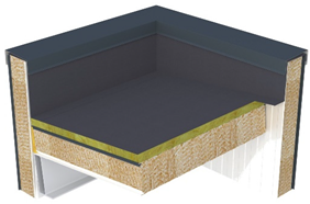
Abstract
The use of innovative insulating materials can contribute to an energy-efficient design by improving the thermal performance of building envelopes while also reducing the embodied energy of materials. Ultra-low carbon steel envelope solutions with bio-based insulations are aligned with this approach. However, fire safety aspects in general and smoldering issues in particular need to be considered when using bio-based insulations. Accordingly, this paper proposes a system-level assessment of the fire performance of steel envelopes with bio-based insulations, not only identifying potential smoldering issues of the core material but also defining and evaluating strategies that could address these concerns within the system design. For this purpose, the variables that could affect the fire performance of wood fiber insulation sandwich panels were identified while considering the different stages of the smoldering phenomena, such as the influence of the joint design or mounting provisions for the initiation, the existence of air cavities, oxygen entrances or physically continuous materials with a tendency to smolder for the continuation, or the inclusion of limiting elements or mitigation layers for spread limitation. Finally, strategies for fire-safe enclosures using bio-based insulations are proposed, assuming smoldering affections in wood-derived materials and analyzing possible mitigation elements at the system level.
1. Introduction
The building sector is adopting new approaches to energy-efficient design. This includes improving the thermal performance of building envelopes and reducing the embodied energy of materials, which accounts for around 11% of global emissions [1]. The development of innovative materials, such as bio-based insulation materials or ultra-low carbon steel envelope solutions, can contribute to such goals. Moreover, lightweight and easy-mounting solutions can contribute to reductions in environmental impacts and construction costs [2], with steel envelope systems with bio-based insulations in general and sandwich panels with wood fiber insulation in particular an interesting option in the mentioned approach.
The energy performance of sandwich panels with different insulation materials has been extensively studied in the literature and products with feasible performance levels have been created. However, the fire performance of these panels can vary depending on the core material, as these materials behave differently in the event of fire regarding factors such as fire propagation and smoke release [2]. In this regard, mineral wool insulation core panels are attributed to high fire resistance or reaction to fire classes while polymeric insulations can contribute to fire fuel loads or even release toxic fumes in an event of fire. Moreover, the physical nature of the material (anisotropy of material) or the design of the joint between panels can also affect fire performance. Previous studies have shown that the fiber orientation of mineral wool affects the thermal parameters of sandwich panels [2] and that joints play an important role in the fire resistance performance of PIR core panels, as the insulation performance of a joint area is similar to the insulation performance of a panel area for joint gaps < 5 mm while registering much higher temperatures in the joint areas for joint gaps ≥ 10 mm, resulting in an anticipated insulation failure of sandwich panel systems [3]. Meanwhile, the fire performance of wood fiber insulation sandwich panels has not been evaluated in the literature, as initial research has mainly focused on studying the material properties of the insulation [4]. It should be added that specifications for wood fiber insulations are included in the product standard EN 13171 [5]. But this type of insulation is not yet included in EN 14509 [6], the product standard for factory-made double skin metal faced insulating sandwich panels, where rigid polyurethane, expanded polystyrene, extruded polystyrene foam, phenolic foam, cellular glass or mineral wool insulation cores are considered.
Furthermore, fire safety assessment methods for sandwich panels have also been discussed in the literature. EN 14509 [6] refers to the Single Burning Item (SBI) test (EN 13823) [7] as a method to assess the reaction to fire performance of sandwich panels, which is based on the Room Corner Test (ISO 9705) [8] as a reference scenario. This approach is now applicable in all of Europe. From a research perspective, ISO TC92 SC1 proposed a Self-Standing Room Test (ISO 13784-1) [9] to predict the behavior of joints and mechanical fastenings as an adaptation of ISO 9705. Moreover, several testing proposals have been presented in the literature over the years for the fire performance of sandwich panels, such as a modified room corner test with increased fire load [10] to adapt fire scenarios to fires in commercial premises or a self-standing box test [11,12] as screening method for EN 13784-1 [9]. It should be added that reactions to fire test methods may not reveal some phenomena that could arise in a fully developed fire scenario [13]; that is why, for example, the ISO 13784-2 scenario is used in complement with SBI results and toxicity analyses in the case of fire engineering studies in France for the public building of PUR panels only in order to establish an official field of application papers with minimal geometric dispositions to respect (minimum height of building, minimum volume) [14]. Similarly, when it comes to the fire performance of facades, intermediate or large-scale fire tests where mounting conditions fully replicate the end-use condition of panels have been proposed [15].
Bio-based insulations have been presented as an ecological alternative concerning sustainability aspects [1], but fire safety could become an issue for insulation materials from renewable raw materials if we consider smoldering aspects [16,17]. Smoldering is a flameless form of combustion in which an oxidation reaction takes place on the surface of a solid fuel rather than in the gas phase surrounding the fuel, as occurs in flaming combustion. It is an incomplete oxidation reaction and therefore releases larger quantities of carbon monoxide but at a slower rate per unit of time, making it difficult to detect [17,18,19]. Compared with a flaming fire, the characteristic temperature (around 500–700 °C for peak temperature), heat released (6–12 kJ/g for the average heat of combustion) and spread rate (around 10–30 mm/h) are lower [18,20]. However, ignition is more likely at low temperatures and the spread can be persistent or self-sustained due to the low oxygen concentrations needed [17,19]. Therefore, wood fiber insulation or other similar materials could face smoldering problems, as physical and chemical factors that can affect this phenomenon may be present. On the one hand, the permeable nature of fuel particles could permit oxygen transport to a reaction site while the material nature itself could slow heat losses allowing for sustained combustion, while on the other hand, char oxidation could become the principal heat source of the self-sustained smolder propagation process. Furthermore, the relative direction of the oxygen supply and smolder propagation can also significantly affect the process [20]. Finally, it should be added that smoldering fires can result in flaming fires, as the transition takes place if the pyrolysis gases generated during this process ignite [19].
Different test methods for the assessment of the smoldering of thermal insulations, such as EN 16733, BS 5803-4, NT FIRE 035, ASTM C739-21a, 16 CFR 1209, CAN/ULC-129-15 and DIN 4102-15&-16, have been gathered in the literature [19]. Test methods differ regarding specimen nature, dimension or positioning, and heat source because of the differences in the fire performance aspects studied or the selected end-use of the product. Numerical models, including a model for the smoldering evaluation of bio-based insulations considering reaction and transport processes, have also been proposed [16]. However, all of them are related to the material itself, considering smoldering as a material property, and not to the constructive system, which material geometry or adjacent materials could affect [19]. Considering this gap, CEN/TC 127/WG 4 has already started to work on the redevelopment of the test method EN 16733 [21].
Material-level fire tests, including smoldering tests, can be useful for product development in today’s emerging sustainable approaches including bio-based materials. For instance, the better fire reaction performance of crop by-products has been showed in comparison with polystyrene and polyurethane insulations [22]. Moreover, flame retardants have been proposed and investigated as additives for fire safety improvement of bio-based insulation materials [23,24], such as the use of boric acid and aluminum hydroxide to reduce the smoldering combustion process [25] or the use of alginate as a binder to reduce the total heat release and the peak of the heat release rate [22]. The addition of inorganic materials such as gypsum or cement has also been investigated to improve the fire performance of bio-based materials [26], as has the partial carbonization of biomass to increase the ignition temperature of materials [27]. Accordingly, although knowledge related to the fire safety performance of bio-based materials and envelope systems made of bio-based materials is increasing, testing at the system level is necessary. As in the case of combustible materials, it is sometimes difficult to further improve the material properties themselves, but it is possible to control fire spread phenomena at the system level. Hence, assessment procedures at this level are necessary.
Existing studies related to the fire safety assessment of bio-based materials at the system level are closely related to the fire propagation evaluation of façades. On the one hand, guidelines for façades including bio-based materials were presented within the COST Action FP1404, focusing on wood cladding façades. Protective methods that prevent the spread of flames from a flashover compartment fire across a façade are listed to avoid the contribution of bio-based materials to the development and spread of fire (window characteristics, use of sprinklers or fire-retardant treated materials, etc.) together with the use of fire stops capable of limiting horizontal or vertical fire spread in air cavities [28]. On the other hand, bio-based insulations in ETICS were evaluated regarding fire safety using a thermographic camera to assess whether there was smoldering and demonstrating the effectiveness of protective elements such as 30 mm plaster to prevent a wood fiberboard from smoldering or stone wool barriers to prevent subsequent self-propagation [29]. The idea is that although this type of material could suffer from smoldering, this problem could be solved, limited or controlled within a construction system, considering specific design strategies.
In this context, the fire performance assessment of bio-based materials in sandwich panels, including specific smoldering evaluation, is also considered necessary at the system level. Therefore, the objective of this paper is to propose a system-level assessment of the fire performance of steel envelope systems with bio-based insulations, not only identifying potential smoldering issues of the core insulation but also defining and evaluating strategies that could address these concerns within the system design that cannot be achieved at the material level. For that purpose, the variables or concepts that could affect the fire performance of wood fiber insulation sandwich panels have been identified while considering the different stages of the smoldering phenomena: initiation, continuation and limitation.
2. Materials and Methods
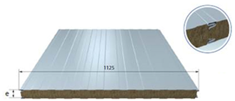
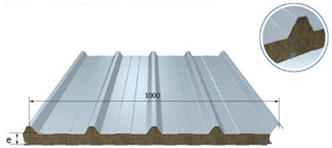
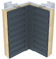
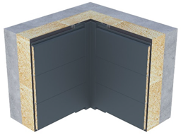
Five steel envelope systems from Joris Ide Group and Monopanel SAS with bio-based insulation cores were studied, considering both prefabricated sandwich panels and site-assembled façade systems (Table 1). The two prefabricated systems were made of sandwich panels with steel facings and a wood fiber insulation core of 150 mm: a cladding sandwich panel (system 1) and a pitch roofing sandwich panel (system 2). The three site-assembled systems refer to a double skin cladding system with a wood fiber insulation material, with a total thickness of 265 mm (system 3), a façade cladding system made of bordered plank containing bio-sourced boards of 30 mm and assembled on-site with wood fiber insulation (system 4), and a flat roofing sandwich panel with two steel facings and 200 mm wood fiber core that can be completed by mineral wool insulation and a waterproof membrane assembled on site (system 5). Accordingly, two site-assembled façade systems, two flat sandwich panels (150 and 200 mm) and one profiled sandwich panel (150 mm) were tested.

Table 1.
Bio-based insulation core envelop solutions.
Functional and structural performance evaluations of these wood fiber insulation metal skin sandwich envelope systems have been conducted [30,31,32], including for thermal and hygrothermal, air and water permeability, acoustics, seismic, and structural (bending, diaphragm) or environmental performance (LCA), thus showing the market potential of the developed products. This paper focuses on the general fire performance evaluation and specific smoldering evaluation. To this end and following EN 14509 [6], reaction to fire tests, fire resistance tests and external fire exposure tests were performed. In addition, fire propagation tests at an intermediate scale and smoldering evaluation during and after each fire test were performed to complement the information obtained in the previous tests and perform a complete fire safety assessment of this type of product.
The reaction to fire performance was evaluated using SBI and flammability tests and classified according to EN 13501-1 [33]. The SBI test (EN 13823 [7]) evaluates the potential contribution of a product to the development of a fire under a fire situation simulating a single burning item in a room corner nearby the product. Meanwhile, the flammability test (EN ISO 11925-2 [34]) determines the ignitability of products by direct small flame exposure at zero impressed irradiance, and it is used to complete or confirm a classification obtained from the SBI test. For the SBI test, the Fire Growth Rate index (FIGRA), the Total Heat Release (THR), the Smoke Growth Rate index (SMOGRA) and the Total Smoke Production (TSP) are evaluated and registered. Visual observations are also conducted to verify the lateral spread of the flame and to detect the fall of flaming particles and droplets. Additionally, the smoldering phenomenon is evaluated using a thermographic camera and two thermocouples that monitor the corner of the sample.
The external fire performance of roofs is assessed using test method 1 of CEN/TS 1187 [35] and classified according to EN 13501-5 [36]. The test determines the performance of roofs to external fire exposure considering the fire spread across the external surface of the roof, the fire spread within the roof, the fire penetration and the production of flaming droplets or debris falling from the underside of the roof or from the exposed surface. Moreover, at the end of the test, the roof is opened and checked for non-flaming fire propagation and any penetration, confirming any smoldering evidence.
The fire resistance performance of vertical envelope systems is evaluated using fire resistance tests of non-loadbearing elements (EN 1364-1 [37]) and classified according to EN 13501-2 [38]. The aim is to assess the ability of a non-loadbearing wall specimen to resist the spread of fire from one side to another by subjecting them to the standard heating or temperature rise curve that simulates a fully developed fire in a compartment. During the test, the passage of flames or hot gases, the appearance of openings, and temperatures are evaluated and registered in the unexposed side of the sample. Additionally, internal thermocouples and a thermographic camera are used for the evaluation of the horizontal heat transfer between system elements.
In the absence of a harmonized European test, the fire propagation of vertical envelope systems is evaluated using an external façade fire spread scenario at an intermediate scale. For this purpose, an internal procedure developed by Tecnalia is used, based on ISO 13785-1 [39] as a testing procedure and the new European approach under development [40] for performance and classification purposes. ISO 13785-1 specifies a screening method to determine the reaction to fire of façade materials and constructions exposed to a simulated external fire with flames acting directly on the façade. A similar scenario is used in the internal procedure developed by Tecnalia, but the heat release is increased up to 300 kW (100 kW is used in ISO 13785-1), resulting in a more severe setup that is closer to a real scenario. This adaptation is based on the heat release used in DIN 4102-20 [41], which is the reference scenario of the developing European test method of medium fire exposure [40]. The second difference is in the test specimen, which consists of a single front wall system, including all the components that are part of the cladding system in the end-use condition (Figure 1). Finally, the position of the burner is adjusted so that it faces the front of the façade to ensure similar flame affection in the lintel detail and the façade surface in all tested systems.
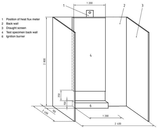
Figure 1.
Testing infrastructure and test specimen. Dimensions in mm.
The main parameters registered during the test are heat flux and temperatures, but observations, including the time of occurrence (such as the ignition of the test specimen), the flame spread up to the height of thermocouples, flames emerging from a cavity behind the outer surface, and falling and/or burning parts, are also recorded. The test is ended after 30 min or when the upper edge of the test specimen is extensively flaming. ISO 13785-1 does not determine any pass/fail criteria, so tests results refer to the obtained data, which are the following: heat flux as a function of time in a graph, thermocouple temperatures as a function of time in graphs, maximum value of heat flux, description of the fire development (photographs) and observations during the test.
As part of the internal procedure, however, Tecnalia uses some performance criteria and classification methods that are defined for other fire propagation test methods [40] as a reference to evaluate the test results. Accordingly, a temperature limit is stablished at a specific distance above the combustion chamber during the test. Continuous flaming in the same area and damage of the specimen are also assessed. Additionally, the smoldering phenomenon is evaluated using a thermographic camera and internal thermocouples.
Accordingly, a smoldering assessment of bio-based insulations at the system level was proposed to be conducted based on the previously presented fire tests and including the following evaluation techniques:
- Temperature measurement within the wood fiber insulation using internal thermocouples. Measurements were recorded during the fire tests and after SBI tests. During the test, the maximum temperature reached could be identified, and after the test, the smoldering phenomenon curve could be recorded. For that purpose, two thermocouples located at a 500 mm height and mid-depth of wood fiber insulation were used in the SBI test: TC1 located in the corner and TC2 located at 500 mm from the corner. In this regard, temperatures registered during the test and in the following hours were monitored to identify temperature peaks related to the combustion process of the wood fiber insulation until the total combustion of the insulation happened (ambient temperatures again recorded). During the intermediate-scale fire test, the distribution of thermocouples throughout the sample at the mid-depth of each system layer enabled us to identify any possible combustion processes of the wood fiber insulation.
- Visual evaluation of the distribution of temperatures using a thermographic camera. Thermographic images were recorded after the SBI and fire propagation tests at the intermediate scale to identify a possible self-sustained smolder propagation process, evaluate its spread along the system, and conclude its limitation or extinction. Additionally, thermographic images were also used during fire resistance tests to evaluate the horizontal heat transfer between system elements.
- Finally, the envelope system was disassembled after each test, and the smoldering process was monitored. The aim was to check the damage produced by the smoldering and to examine any possible re-ignition or to identify the effectiveness of the adopted fire safety design strategies.
To conclude, after defining the variables that could affect the smoldering process, strategies that address these concerns within the system design were proposed and evaluated at the system level. For that purpose, some of the tests were repeated after implementing the defined strategy.
Table 2 includes a summary of the experimental campaign, including the tests performed in this research considering the different envelope systems (systems 1–5), the defined evaluation methods (reaction to fire, external fire exposure, fire propagation and fire resistance), the smoldering assessment mechanisms, and the implemented design strategies.

Table 2.
Summary of proposed test campaign.
3. Results
This section includes two aspects. On the one hand is a general fire performance of the systems considering reaction to fire, external fire exposure, propagation of fire and fire resistance, and a performance comparison of products with different core insulation materials. On the other hand is a specific smoldering evaluation of the systems using different fire tests. The latter includes the identification of variables that affect the different stages of this phenomenon, as well as the proposal and validation of design strategies that could improve the smoldering performance of the studied envelope systems.
As a general fire performance evaluation of the envelope systems, Table 3 summarizes the fire performance of the bio-based materials in the sandwich panels considering the reaction to fire (EN 13501-1 [32]), external fire exposure (EN 13501-5 [36]), propagation of fire (internal procedure) and fire resistance (EN 13501-2 [38]) of the envelope systems.

Table 3.
Summary of test results.
Regarding reaction to fire and fire resistance, a comparison of the fire performance of the prefabricated sandwich panels is presented in Table 4 considering different core insulation materials. For the benchmarking analysis, commercially available products were checked for mineral wool (MW) and polyisocyanurate (PIR) insulation panels, while research results were used for wood fiber insulation (WF) panels.

Table 4.
Fire performance of prefabricated sandwich panels depending on the core insulation material.
For external fire exposure, a classification without further testing (CWFT) is possible for mineral wool and polyurethane (PUR, including PIR) core sandwich panels according to EN 14509 [6] and the Commission Decision of 4 September 2006 [42] when certain provisions are fulfilled (Table 5). The Commission Decision does not cover wood fiber core panels due to the novelty of the material, but early experimental research has shown that a BROOF (t1) classification can also be achieved by maintaining similar specifications. Further research is needed in this regard.

Table 5.
Classes of external fire performance for double skin metal faced sandwich panels for roofs according to the Commission Decision of 4 September 2006 [42].
In general, the results of the tests on the WF insulation core systems showed less favorable reactions to fire and fire resistance performance than the MW insulation sandwich panels, though their results were similar to those of the PIR core sandwich panels. However, when presenting a WF insulation core as an ecological alternative in terms of sustainability, the propensity for continuous smoldering should be taken into account. Accordingly, the variables or concepts that affected the fire performance of the WF insulation sandwich panels were identified considering the three stages of the combustion or smoldering phenomena:
- Initiation: smoldering/combustion starts because the fire penetrates the system or heats the insulation to the extent that a flameless combustion process is initiated;
- Continuation: smoldering/combustion persists (self-sustained) or grows (oxygen entry increase);
- Limitation: smoldering/combustion is slowed down or stopped until extinction.
3.1. Initiation: Combustion/Smoldering Starts
Several tests were used to evaluate the possibility of ignition or smoldering initiation of the systems: reaction to fire tests (EN 13823 [7] for the SBI test and EN ISO 11925-2 [34] for flammability test) for all envelop systems, and the external fire exposure test (test method 1 of CEN/TS 1187 [35]) for roofs.
The flammability tests demonstrated that the wood fiber insulation is susceptible to ignition when exposed to direct flame impingement. Consequently, the envelope system should prevent flames from reaching the insulation, as well as any temperature rise that could result in smoldering. In this regard, junctions between panels or with other elements (joints between panels, façade details or connections to slabs) and the design of the joint itself (type of joint, joint width, joint material or distance between fixings) could especially affect the fire performance of sandwich panels.
For the SBI tests, the assembly of the test samples for metal sheet systems (double skin) was defined by EN 14782—Self-supporting metal sheet for roofing, external cladding and internal lining - Product specification and requirements [43]. According to the standard, the maximum distance between fixations is 360 mm, the maximum distance to edges is 30 mm and the overlapping of metal sheets at joints is 40 mm. Meanwhile, sandwich panels were assembled according to EN 14509—Self-supporting double skin metal faced insulating panels - Factory made products - Specifications [6]—using corner flashings and with screws every 400 mm. In both cases, the vertical joints included in the long wing and the corner flashings were critical for fire penetration.
Based on the reaction to fire tests, the sandwich panels (systems 1, 2 and 5) obtained a B-s1,d0 classification while the metal sheet systems (double skin systems 3 and 4) obtained B-s2,d0 (Table 6), even if a thicker metal sheet was used and the mounting system did not directly represent the reality (ventilated cavities or air cavities and internal profiles were not represented in the test). For the sandwich panels, as the same inner steel sheet thickness was used, results differed depending on the shape and dimensions of the joint material for systems 1 and 2 and the insulation thickness and lack of joint material in system 5.

Table 6.
Results for the SBI tests for prefabricated and on-site façade systems.
Additionally, a clear smoldering phenomenon was observed in all SBI tests. The heat was stored within the system and the insulation material was burning internally and releasing smoke for hours or even days. During the monitorization of the double skin system (systems 3 and 4) using internal thermocouples (Figure 2), an increase in the temperature that started at minute 12 was only registered by TC1 during the fire test (21 min exposition time). After the test, the sample was turned upside down and temperatures reached 700 °C, which was related to the combustion process of the wood fiber insulation. Two and a half hours were measured between the recorded peaks, the time it took to travel the 350 mm distance between the thermocouples. The combustion of the insulation in this area was completed after 8 h when ambient temperatures were recorded again.

Figure 2.
Temperature increases registered in the SBI test: (a) during the test and (b) after the test; (c) location of thermocouples (TC1 and TC2 were located at the mid-depth of the wood fiber insulation, and TC1 was located in the corner at a distance dependent on the panel thickness).
Considering all tested systems, TC1 reached temperatures of between 50 and 82° during the tests, with the temperature increase starting between 8 and 15 min. TC2 continued increasing its temperature after the finalization of the tests, proving the existence of the smoldering phenomenon. The same phenomenon was detected for all the systems. For the sandwich panels (systems 1, 2 and 5), the samples were still smoldering and almost all the insulation was consumed after one day of monitorization. Monitorization using a thermographic camera allowed us to evaluate the process (Figure 3, Figure 4 and Figure 5). In one of the cases, flaming even started two hours after the finalization of the test (Figure 5).

Figure 3.
Images of the double skin cladding (systems 3 and 4): (a) 1 h after the test; (b) 1.5 h after the test; (c) 17 h after the test.

Figure 4.
Images of the sandwich panel (system 5): (a) 1 h after the test; (b) 4 h after the test; (c) 19 h after the test.

Figure 5.
Images of the sandwich panel (system 2): (a,b) after the test; (c,d) 2 h after the test.
The roofing envelope systems were evaluated using the BROOF t1 test to determine their performance regarding external fire exposure. For the different sandwich panels tested, the fire penetrated through the joint between two panels and the wood fiber insulation caught fire, causing the test to fail due to internal incandescent combustion (fire penetration) (Figure 6). Internal incandescent combustion was not detected at the end of the test when the panels were fixed to a substructure and stitching screws were used each meter to simulate a much more real mounting condition (Figure 7). This means that the pass or fail condition could depend on the system configuration and the mounting conditions; hence, deformation or damage during the service life could lead to failure because of fire penetration and the smoldering of the wood fiber insulation. Accordingly, several parameters could affect a roof system’s behavior when exposed to external fire:
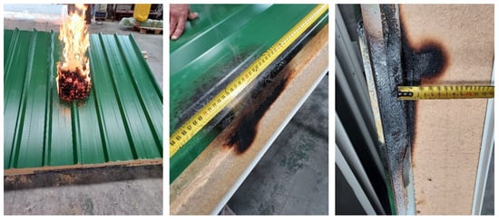
Figure 6.
Pictures of the sample (system 2) during and after the test.
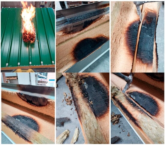
Figure 7.
Pictures of the fixed sample (system 2) during and after the test.
- Sample fastened or not fastened and distance between fixings;
- Use stitching elements and distance between them;
- Type of joint used (dimensions and combustible materials);
- Sensibility of the mounting.
In summary, in all SBI and BROOF tests, the fire penetrated the system and reached the wood fiber insulation. This behavior will depend on the joints and fixings (+assembly), as well as the fire scenario. Seeing that fire is going to enter regardless, it is important to understand how or why it spreads and how to stop it.
3.2. Continuation: Smoldering/Combustion Persists or Increases
The propagation of fire for the vertical envelope systems was evaluated using an external façade fire spread scenario according to an internal protocol described in Section 2 (Figure 8). Samples consisted of single front wall systems (around 2 m wide × 3 m high), which were representative of a system used in practice and included the construction details of joints, fixings, lintel detail, etc., assembled as in practice. Samples were closed with non-combustible material in their sides to avoid any flame or extra oxygen entrance from those areas.
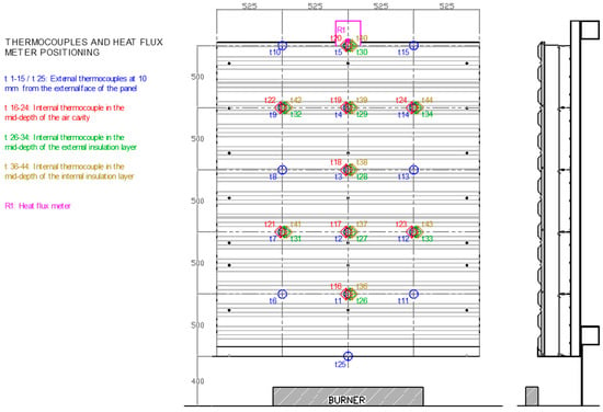
Figure 8.
Location of thermocouples throughout sample surface and at the mid-depth of each system layer in systems 3 and 4.
The profile façades or cladding systems (double skin cladding system (system 3) and façade cladding system (system 4) did not meet the criteria established to determine a favorable behavior of the specimen regarding its fire spread, since flame propagation occurred vertically beyond the upper limit of the test specimen through the combustible components and/or air cavities within the test specimen (Figure 9). However, the façade made of wood fiber insulation sandwich panels (systems 1) met the criteria since there was no vertical flame propagation beyond the upper limit of the test specimen, there were no burning fragments falling from the façade, and the established temperature limits were not reached (Figure 10). The temperatures recorded inside the samples easily represent the fire spread that occurred within the sample (Figure 11 and Figure 12). While the external cladding temperatures were 400–700 °C at one meter high and 200–300 °C at two meters high for both profile façade systems and sandwich panels, the internal temperatures differed from one system to other. The maximum temperatures in the wood fiber insulation of the sandwich panels were around 100 °C. Meanwhile, internal thermocouples in the air cavities, omega profiles and even the internal insulation layer of the profile façades (continuous black in Figure 11) reached higher maximum temperatures than the external cladding of 850 °C, 950 °C and 700 °C, respectively, at 1 m high. According to the protocol, the tests were finished at 30 min, but the samples were not extinguished, so the smoldering effect was also evaluated after the tests using a thermographic camera.
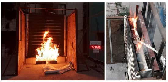
Figure 9.
Pictures of the double skin sample (system 3) during the test.
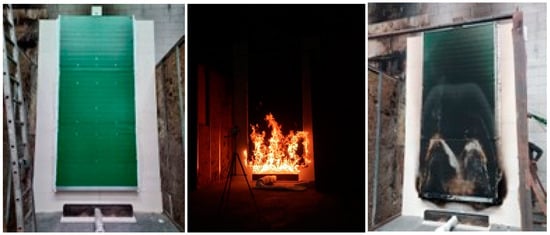
Figure 10.
Pictures of the sandwich panel sample (system 1) before, during and after the test.
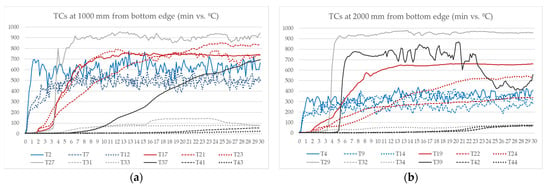
Figure 11.
Temperatures recorded at 1 m (a) and 2 m (b) height in system 3: BLUEs_external face, REDs_small omega and membrane, GREYs_120 mm omega and insulation, BLACKs_90 mm insulation.
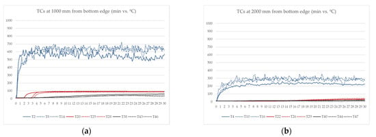
Figure 12.
Temperatures recorded at 1 m (a) and 2 m (b) height in system 1: BLUEs_external face, REDs_insulation, BLACKs_internal face.
For the double skin system (system 3), a chimney effect generated within the inner omega profiles resulted in a rapid heat transfer to the internal wood fiber insulation, which burned during the test (Figure 9 right). In consequence, the smoldering effect was much more rapid than in the SBI tests and the insulation was consumed before four hours in the case of on-site profile façades (Figure 13). For the sandwich panel façade (system 1), the effect was slow because the sample was closed in its sides; hence, there was not any relevant entrance of oxygen within the sample. The insulation was consumed slowly in the following days. After 10 days, the sample was dismantled to check the smoldering progress. The insulation of the bottom panel was totally consumed, while the insulation of the second panel ignited due to the oxygen increase after opening the joints and separating the steel faces, providing evidence that the smoldering effect continued at that moment (Figure 14).

Figure 13.
Thermographic images of the double skin system (system 3): (a) 10 min after the test; (b) 1.5 h after the test; (c) 3 h after the test.

Figure 14.
Thermographic images of the sandwich panel (system 1): (a) 2 days after the test and (b,c) during the dismantling 10 days after the test.
In summary, given the physical nature of the material, façades incorporating wood fiber insulation are susceptible to the occurrence of internal fire propagation (glow combustion) or a continuous, self-sustaining smoldering process. The quantity of oxygen reaching the material affects the speed of combustion and propagation. Therefore, the design of joints and façade details or air cavities (also consider the chimney effect) should be considered. The lower the oxygen input, the less chance of internal combustion, as it will be more difficult to reach by such high temperatures or flame, or the slower the rate of propagation of either flame or flameless combustion. Furthermore, alterations in oxygen concentration, such as through the creation of openings or the disassembly of façade elements, can result in re-ignition.
3.3. Extinction or Limitation: Combustion/Smoldering Is Slowed Down or Stopped
Two tests were used to evaluate the possibility of the limitation or extinction of smoldering within the systems: the fire propagation test for façades (according to the internal protocol described in Section 2) and the external fire exposure test (test method 1 of CEN/TS 1187 [35]) for roofs. Based on the previous results, two strategies were evaluated: the closure, sealing or limiting of air cavities and gaps and the use of non-combustible materials as a mitigation layer or element.
To evaluate the effectiveness of the closure of cavities, mineral wool insulation was installed within the omega profiles of the second type of profile façades (system 4, Figure 15a,b) to prevent the chimney effect produced in the first profile façade system (system 3) during the fire propagation test (Figure 15c,d). This modification resulted in significant reductions in temperatures at the top of the omegas and within the insulation (continuous black in Figure 16) compared with the initial profile façade test (system 3, continuous grey and black in Figure 11); however, this only delayed the ignition of the internal material by a few minutes (Figure 16). The cladding also featured the same insulation, which on the one hand prevented direct heat transmission between metal elements but on the other hand exposed combustible material to the air cavity, where the uninterrupted vertical airflow within the cavity continued to pose a fire hazard. In addition, this insulation material was located close to the exterior face of the façade where the joints between cladding panels were again an essential variable for the ignition or smoldering initiation of the insulation material. In this regard, fire propagation performance was improved by installing mineral wool insulation within the inner omega profiles, creating a slower heat transfer to the internal insulation material, but the fire propagation evaluation criteria were still not fully fulfilled and smoldering was produced (Figure 15b), although it was slower than in the double skin cladding system. Accordingly, smoldering was slightly faster in the sample where air cavities existed within the omegas (Figure 15c). This means that the closure of some of the air gaps and the consequent reduction in the oxygen entrance delayed the initiation or the spread of the smoldering phenomenon but did not limit or stop it, suggesting that further modifications, such as the implementation of open state fire barriers or fire-stopping measures to prevent flame spread and heat transfer, are necessary to ensure optimal fire safety in these façade systems.

Figure 15.
Images of the site-assembled systems before and 30 min after the termination of the test: (a,b) system 4, façade cladding system, and (c,d) system 3, double cladding system.

Figure 16.
Temperatures recorded at 1 m (a) and 2 m height (b) in system 4, BLUEs_external face, REDs_small omega and membrane, BLACKs_200 mm omega and insulation.
As a second strategy, the use of a mitigation layer or element, such as the use of non-combustible materials as insulation barriers, was evaluated. For that purpose, a second façade system composed of wood fiber insulation sandwich panels and an intercalated mineral wool insulation sandwich panel was tested considering the propagation of fire (Figure 17a). In this regard, although the test results and recorded temperatures were similar, there were differences in the smoldering propagation since the panel composed of non-combustible material made it possible to stop the self-sustaining process. In the case of the first sandwich panel façade (system 1, fully made of wood fiber insulation), the fire reached the second panel (Figure 17c,d), but in the second, smoldering was stopped by the mineral wool sandwich panel once all the insulation of the first panel was consumed (Figure 17a,b), showing the effectiveness of the chosen strategy.

Figure 17.
Images of prefabricated sandwich panel before and after the test: (a,b) solution with intermediate mitigation layer panel 4 days after the termination of the test; (c,d) system 1, solution without intermediate mitigation layer panel 10 days after the termination of the test.
For the roofing systems, the use of mineral wool insulation was evaluated as a mitigation layer in the external fire exposure test as a top layer of the sandwich panel comprising a typical envelope system with the following layers from inside to outside: wood fiber insulation sandwich panel, mineral wool insulation, and waterproofing membrane. The system (system 5) composed of unprotected sandwich panels showed internal incandescent combustion within the wood fiber insulation material in the joint areas between panels (Figure 18), while the protected system (more precisely, the mineral wool insulation installed on the top of the sandwich panels) was able to stop the penetration of the fire through the joint between panels preventing the wood fiber insulation catching fire (Figure 19), obtaining a BROOF (t1) classification according to EN 13501-5 [36].
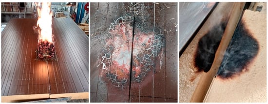
Figure 18.
Pictures of the unprotected sandwich panels during and after external fire exposure.
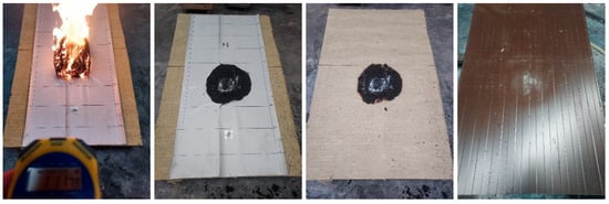
Figure 19.
Pictures of the protected layered roofing system during and after the external fire exposure test.
Additionally, the heat transfer between metallic elements should also be considered. This aspect was considered especially relevant for the in situ systems (systems 3 and 4) since metallic elements were used in all layers of the envelope systems, even if different insulation layers were included. Both envelope systems were composed of several layers of metal sheets, insulations and profiles (Figure 20). The back trays were fixed to two vertical steel profiles, the first insulation layer was inserted in the back trays, and the second layer was placed after 4 vertical omega profiles were fixed. In the external face, 20 mm spacers were installed to fix the final trapezoidal sheeting in the double skin cladding system or cassettes in the double skin cladding with the façade product.

Figure 20.
Components of the in situ double skin cladding systems: (a) back trays and first insulation layer; (b) omegas and second insulation layer; (c) membrane, spacers, and external cassettes; (d) trapezoidal sheeting.
Both envelope systems were classified EI45 as a partition or EI30 (i→o) as an external wall according to EN 13501-2 [38]. The classifications considering only integrity criteria were E90 and E60 for the double skin (system 3) and façade cladding systems (system 4), respectively, meaning that temperature failure was reached before the fire reached the external face of the envelope system. Hence, internal thermocouples located in each envelope layer and a thermographic camera were used to show a quick heat transfer within the system. The internal thermocouples showed a quick heat transfer between the metallic elements since elevated temperatures were detected earlier in the omegas and spacers than in the second insulation layer, recording temperatures of between 307 and 470 °C for the first one, temperatures of between 64 and 91 °C for the second one at minute 50 during the test of system 3 (Figure 21b), and temperatures of between 415 and 539 °C or 70 and 121 °C, respectively, for system 4 (Figure 22b). The thermographic camera also visually showed the mentioned heat transfer through the different layers (Figure 21a). However, the nature of the external cladding could have disturbed the internal heat transfer detection, as it was detected in façade cladding system 4 (the cassettes contained a 30 mm insulation layer inside) (Figure 22a). Elements that break the contact between metallic elements should be considered for limiting the rapid heat transfer between the internal and external sides of facades.
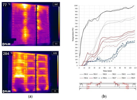
Figure 21.
Fire resistance test of system 3: (a) thermographic images at 40 and 105 min of the test and (b) temperatures recorded within the different layers of the sample: BLACKs_exposed sheet, GREYs_internal insulation, REDs_omegas and spacers, BLUEs_external insulation and membrane.
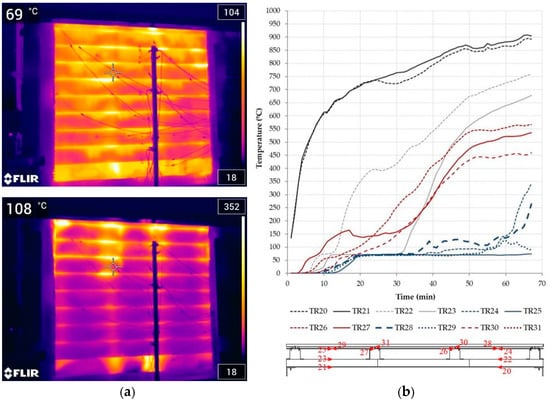
Figure 22.
Fire resistance test of system 4: (a) thermographic images at 40 and 65 min of the test and (b) temperatures recorded within the different layers of the sample: BLACKs_exposed sheet, GREYs_internal insulation, REDs_omegas and spacers, BLUEs_external insulation and membrane.
4. Discussion
The fire performance assessment of bio-based materials in sandwich panels or site-assembled insulated profile systems has been proposed at the system level. In this regard, the use of different tests facilitated the evaluation of smoldering, focusing on its different stages:
- Initiation: smoldering/combustion starts;
- Continuation: smoldering/combustion persists or grows;
- Limitation: smoldering/combustion is slowed down or stopped until extinction.
4.1. Initiation: Combustion/Smoldering Starts
The initiation of smoldering was measured using SBI and BROOF tests. The test results differed depending on the fastening of the panels, the type of joint used (dimensions and extra materials), the use of stitching elements and the distances between them, and the accuracy of mounting itself. However, the smoldering phenomenon or even internal incandescent combustion was always observed during or after the tests.
In the SBI tests, internal thermocouples located in front of the fire source reached temperatures of between 50 and 82° during the tests, starting the temperature increase between 8 and 15 min. Thermocouples located outside the fire source area did not suffer any remarkable temperature changes during the tests but continued increasing temperature after finalization. In this regard, temperatures reached 700 °C, and the combustion of the insulation was completed after 8 h when ambient temperatures were recorded again. The temperature reached was related to the combustion process of the wood fiber insulation, proving the existence of the smoldering phenomenon. A vertical spread rate of 2.33 mm/min was measured based on the time measured between the recorded temperature peaks of the thermocouples. In the BROOF tests, the failure mechanism refers to internal incandescent combustion (fire penetration) for the tested wood fiber insulation facades, which the following parameters could affect:
- Fastening of sample to the substructure and distance between fixings;
- Joint stitching elements and distance between them;
- Type of joint (dimensions and combustible materials);
- Sensibility of the mounting.
4.2. Continuation: Smoldering/Combustion Persists or Increases
The continuation of smoldering was measured using fire propagation tests at the intermediate scale, being mainly influenced by the existence of cavities, oxygen entrances, or the existence of physically continuous materials with a tendency to smolder.
The external cladding temperatures were similar for the profile façade and sandwich panel facades (400–700 °C at one meter high and 200–300 °C at two meters high). However, the internal insulation maximum temperatures went from 100 °C in the sandwich panels to 700 °C in the profile facades at 1 m high, where a chimney effect was generated within the air cavity of the inner omega profiles. This resulted in a rapid heat transfer to the internal wood fiber insulation, which burned during the test and was consumed before four hours. In this case, the smoldering effect was much more rapid than in the SBI tests.
For the prefabricated sandwich panel façades, the smoldering effect was slower (several weeks) because there were not air cavities in the façade system and oxygen entrance was limited to the joints between panels. Hence, for facades without cavities, smoldering continues until insulation is consumed, but the re-ignition of flaming fire occurs if oxygen entrance is increased, e.g. when the system dismantles.
4.3. Extinction or Limitation: Combustion/Smoldering Is Slowed Down or Stopped
Design strategies were proposed for smoldering limitation, and their effectiveness was evaluated by means of intermediate fire propagation tests for facades and external fire exposure tests for roofs.
The external exposure tests of roofs showed that the encapsulation of bio-based materials could avoid the start of the smoldering process. Linear protective elements, such as the use of intumescent joints, can also be investigated to translate this protection to the joint area for sandwich panels. Additionally, the intermediate scale tests showed that the closure of cavities delayed the ignition of the internal material. The latter also reduced the oxygen entrance within the system, resulting in a lower smoldering spread rate. Furthermore, the use of non-combustible materials as a limiting barrier showed the possibility to stop the self-sustaining smoldering process.
Additionally, for site-assembled façade systems (ventilated facades), open state cavity barriers need to be considered and evaluated for properly limiting the fire spread within the continuous cavity. Elements that break the contact between metallic elements should also be considered for limiting the rapid heat transfer between the internal and external sides of cladding systems, as elevated temperatures were detected earlier in the omegas and spacers than in the second insulation layer during fire resistance tests.
5. Conclusions
The benchmarking analysis performed for sandwich panels of different core insulation materials regarding fire performance showed similar results for wood fiber (WF) insulation and PIR insulation sandwich panels. Additionally, bio-based insulation panels include benefits regarding sustainability, reducing carbon emission contributions and hence promoting the decarbonization of the construction sector.
Nevertheless, smoldering could be an issue for materials derived from wood, which can be tackled with different approaches, such as (1) material development based on an evaluation of the insulation material itself at the small scale, (2) the design of the system based on an evaluation of the construction system at the intermediate scale or (3) performance-based design based on a fire engineering study at the building level. Considering the limited room for improvement of this type of material regarding fire performance, this article focused on the second approach, conducting fire performance evaluation at the system level, in which problems were identified but strategies are also proposed and evaluated using intermediate-scale tests. Hence, this work can complement the research conducted at the material level (first approach) and be an input for a building-level study (third approach).
Regarding evaluation methods, the consideration of different fire scenarios is proposed for sandwich panels and site-assembled insulated profile systems. In this regard, propagation tests at the intermediate scale were used to evaluate the fire safety concerns that could arise at the system level, since the intermediate scale can provide information related to some phenomena that cannot be identified at the small scale. The intermediate scale tests, moreover, could simulate end-use applications considering mounting provisions, which may differ from the small scale (mainly related to common product standard mounting and no real end-use mounting). Furthermore, each test could facilitate the evaluation of the smoldering, focusing on its different stages: the initiation stage, evaluated using the SBI and BROOF tests and considering the influence of the joint design or the mounting provisions; the continuation stage, evaluated using fire propagation tests at the intermediate scale and influenced by the existence of cavities, oxygen entrances or physically continuous materials with a tendency to smolder; and the limitation stage, assessed using fire propagation tests at the intermediate scale and external fire exposure tests. Additionally, fire resistance tests of façades ere used to evaluate the horizontal heat transfer between the system elements themselves. In this regard, smoldering assessment was proposed to be conducted using two techniques within the different fire tests: temperature measurements within the wood fiber insultation using internal thermocouples during and after the fire test and the visual evaluation of the distribution of temperatures using a thermographic camera.
The evaluation proposal included assessment methods and techniques, as well as the effectiveness evaluation of the proposed design strategies as part of the evaluation of the limitation stage. Hence, the following design strategies could enable the use of sustainable and innovative materials ensuring fire safety. On the one hand, strategies for the use of bio-based insulations in fire-safe enclosures refer to the consideration of the smoldering phenomenon of materials derived from wood and the introduction of elements to contain it at the system level. In this regard, the encapsulation of materials could avoid the start of smoldering or combustion together with its rapid propagation due to the oxygen entrance, while the inclusion of limiting elements or mitigation layers (non-combustible materials) could stop it. It is also important to consider proper installation and ensure that the original installation specifications are maintained when introducing bio-based insulation materials. On the other hand, the use of site-assembled metal profile systems should consider two main aspects regarding fire safety: first, the consideration of possible heat transfer through metallic elements and the introduction of limiting elements, such as the use of materials with low thermal conductivity, to slow down this transfer; second, the possible fire propagation through cavities and the use of limiting elements to stop or delay this propagation. For the latter, the closure of any not necessarily ventilated cavity or the inclusion of non-combustible materials that are able to compartment or close the ventilated cavities in the case of fire should be considered.
The results obtained in this research were for a very specific type of wood fiber. Hence, the effects of density, fiber orientation, and nature of the wood were not evaluated in the present study. Accordingly, further research is needed regarding these aspects, as they are relevant for the study of the behavior of wood fibers in a fire scenario.
The proposed assessment at the system level enables the introduction of bio-based insulations into steel envelope systems for fire safety, but this assessment can be extrapolated to other types of façade systems since it can be easily adjusted to different systems. However, design strategies are also dependent on the type of selected system, so further work is needed when it comes to the demonstration of each selected strategy.
Author Contributions
Conceptualization, A.E.-I. and X.O.-A.; methodology, A.E.-I. and X.O.-A.; software, A.E.-I.; validation, A.E.-I., X.O.-A. and D.I.; formal analysis, A.E.-I.; investigation, A.E.-I.; resources, T.R. and V.H.; data curation, A.E.-I.; writing—original draft preparation, A.E.-I. and X.O.-A.; writing—review and editing, D.I., T.R. and V.H.; visualization, A.E.-I.; supervision, D.I.; project administration, D.I.; funding acquisition, D.I. All authors have read and agreed to the published version of the manuscript.
Funding
This research was performed within the INCSEB project, which received financial support from the European Community’s Research Fund for Coal and Steel (RFCS) under the agreement N°101033984.
Data Availability Statement
Dataset available on request from the authors.
Conflicts of Interest
Author Thibault Renaux was employed by the company Joris Ide Group. Author Valérie Huet was employed by the company Monopanel SAS. Author David Izabel was employed by the company L’Enveloppe Métallique du Bâtiment. The remaining authors declare that the research was conducted in the absence of any commercial or financial relationships that could be construed as a potential conflict of interest.
Abbreviations
The following abbreviations are used in this manuscript:
| SBI | Single Burning Item |
| ISO | International Organization for Standardization |
| TC | Technical Committee |
| SC | Sub-Committee |
| CEN | European Committee for Standardization |
| WG | Working group |
| ETICS | External Thermal Insulation Composite System |
| PVC | Polyvinyl Chloride |
| LCA | Live Cycle Assessment |
| FIGRA | Fire Growth Rate index |
| THR | Total Heat Release |
| SMOGRA | Smoke Growth Rate index |
| TSP | Total Smoke Production |
| MW | Mineral Wool |
| PIR | Polyisocyanurate |
| WF | Wood Fiber |
| PUR | Polyurethane rigid foam |
| CWFT | Classification without further testing |
| PCS | Gross Calorific Potential |
| EC | European Commission |
References
- Palumbo, M. Contribution to the Development of New Bio-Based Thermal Insulation Materials Made from Vegetal Pith and Natural Binders: Hygrothermal Performance, Fire Reaction and Mould Growth Resistance. Ph.D. Thesis, Universitat Politècnica de Catalunya, Barcelona, Spain, 2015. [Google Scholar] [CrossRef]
- Ablaoui, E.M.; Malendowski, M.; Szymkuc, W.; Pozorski, Z. Determination of Thermal Properties of Mineral Wool Required for the Safety Analysis of Sandwich Panels Subjected to Fire Loads. Materials 2023, 16, 5852. [Google Scholar] [CrossRef] [PubMed]
- Wang, Y.C.; Foster, A. Experimental and numerical study of temperature developments in PIR core sandwich panels with joint. Fire Saf. J. 2017, 90, 1–14. [Google Scholar] [CrossRef]
- Horvathova, M. Facade Insulation from Wood-Fiber Boards in The Burning Process. Transp. Res. Procedia. 2021, 55, 1415–1422. [Google Scholar] [CrossRef]
- EN 13171:2013+A1:2015; Thermal Insulation Products for Buildings—Factory Made Wood Fibre (WF) Products—Specification. European Committee for Standardization: Brussels, Belgium, 2015.
- EN 14509:2014; Self-Supporting Double Skin Metal Faced Insulating Panels—Factory Made Products—Specifications. European Committee for Standardization: Brussels, Belgium, 2014.
- EN 13823:2020+A1:2022; Reaction to Fire Tests for Building Products—Building Products Excluding Floorings Exposed to the Thermal Attack by a Single Burning Item. European Committee for Standardization: Brussels, Belgium, 2022.
- ISO 9705-1:2016; Reaction to Fire Tests—Room Corner Test for Wall and Ceiling Lining Products—Part 1: Test Method for a Small Room Configuration. International Organization for Standardization: Geneva, Switzerland, 2016.
- ISO 13784-1:2014; Reaction to Fire Test for Sandwich Panel Building Systems—Part 1: Small Room Test. International Organization for Standardization: Geneva, Switzerland, 2014.
- Crewe, R.J.; Hidalgo, J.P.; Sørensen, M.X.; McLaggan, M.; Molyneux, S.; Welch, S.; Jomaas, G.; Torero, J.L.; Stec, A.A.; Hull, H. Fire Performance of Sandwich Panels in a Modified ISO 13784-1 Small Room Test: The Influence of Increased Fire Load for Different Insulation Materials. Fire Technol. 2018, 54, 819–852. [Google Scholar] [CrossRef]
- Yoshioka, H.; Tanaka, Y.; Nishio, Y.; Noguchi, T.; Kobayashi, K.; Ohmiya, Y.; Kanematsu, M.; Ando, T.; Naruse, T.; Kagiya, K.; et al. Self-standing Compartment Fire Tests on Sandwich Panels. Fire Sci. Technol. 2016, 35, 19–38. [Google Scholar]
- Yoshioka, H.; Noguchi, T.; Kobayashi, K.; Kanematsu, M.; Ando, T.; Pareek, S.; Hayakawa, T. Development of a new intermediate-scale box test on sandwich panel products compared with ISO 13784-1 room test and EN 13501-1 classification system. Fire Mater. 2021, 48, 1025–1034. [Google Scholar] [CrossRef]
- McLaggan, M.S.; Hidalgo, J.P.; Osorio, A.F.; Heitzmann, M.T.; Carrascal, J.; Lange, D.; Maluk, C.; Torero, J.L. Towards a better understanding of fire performance assessment of façade systems: Current situation and a proposed new assessment framework. Constr. Build. Mater. 2021, 300, 124301. [Google Scholar] [CrossRef]
- Guillaume, E.; Blanc, C.; Sainrat, A.; Joyeux, D.; Rabilloud, A.; Raynaud, A. Application of Fire Safety Engineering to define the domain of application of self-supporting double skin steel faced insulating sandwich panels in public buildings. In Proceedings of the 10th International Conference Fire and Materials, San Francisco, CA, USA, 29–31 January 2007. [Google Scholar]
- Anderson, J.; Boström, L.; Chiva, R.; Guillaume, E.; Colwell, S.; Hofmann, A.; Tóth, P. European approach to assess the fire performance of façades. Fire Mater. 2021, 45, 598–608. [Google Scholar] [CrossRef]
- Sudhoff, P.; Krause, U. A numerical model for predicting the smoldering behavior of bio-based insulation materials: Model theory and validation. Fire Saf. J. 2025, 152, 104351. [Google Scholar] [CrossRef]
- Sudhoff, P. The Smoldering Behavior of Bio-based Insulation Materials Made from Renewable Raw Materials—An Overview. In Proceedings of the 70th Conference of the German Fire Protection Association, Magdeburg, Germany, 6–8 May 2024. [Google Scholar] [CrossRef]
- Rein, G. Smouldering combustion phenomena in science and technology. Int. Rev. Chem. Eng. 2009, 1, 3–18. [Google Scholar]
- Steen-Hansen, A.; Mikalsen, R.F.; Ehrlenspiel, R. Smouldering fire test methods—Documenting the potential for smouldering fires in thermal insulation. In FRIC Report D3.1; FRIC Fire Research and Innovation Centre: Trondheim, Norway, 2023; p. 39. [Google Scholar] [CrossRef]
- Ohlemiller, T.J. Smoldering Combustion. In SFPE Handbook of Fire Protection Engineering, 3rd ed.; Di Nenno, P.D., Drysdale, D., Beyler, C.L., Walton, W.D., Eds.; National Fire Protection: Quincy, MA, USA, 2002; pp. 2200–2210. [Google Scholar]
- EN 16733:2016; Reaction to Fire Tests for Building Products—Determination of a Building Product’s Propensity to Undergo Continuous Smouldering. European Committee for Standardization: Brussels, Belgium, 2016.
- Palumbo, M.; Formosa, J.; Lacasta, A.M. Thermal degradation and fire behaviour of thermal insulation materials based on food crop by-products. Constr. Build. Mater. 2015, 79, 34–39. [Google Scholar] [CrossRef][Green Version]
- Raja, P.; Murugan, V.; Ravichandran, S.; Behera, L.; Mensah, R.A.; Mani, S.; Kasi, A.; Balasubramanian, K.B.N.; Sas, G.; Vahabi, H.; et al. A review of sustainable bio-based insulation materials for energy-efficient buildings. Macromol. Mater. Eng. 2023, 308, 2300086. [Google Scholar] [CrossRef]
- Rodríguez Neira, K.; Cárdenas-Ramírez, J.P.; Rojas-Herrera, C.J.; Haurie, L.; Lacasta, A.M.; Torres Ramo, J.; Sánchez-Ostiz, A. Assessment of Elaboration and Performance of Rice Husk-Based Thermal Insulation Material for Building Applications. Buildings 2024, 14, 1720. [Google Scholar] [CrossRef]
- Palumbo, M.; Lacasta, A.M.; Navarro Ezquerra, A.; Giraldo, M.P.; Lesar, B. Improvement of fire reaction and mould growth resistance of a new bio-based thermal insulation material. Constr. Build. Mater. 2017, 139, 531–539. [Google Scholar] [CrossRef]
- Montesinos-Martínez, M.; Martínez-Gabarrón, A.; Barreca, F.; Flores-Yepes, J.A. A Newly Bio-Based Material for the Construction Industry Using Gypsum Binder and Rice Straw Waste (Oryza sativa). Buildings 2024, 14, 3440. [Google Scholar] [CrossRef]
- Zou, S.; Li, H.; Liu, L.; Wang, S.; Zhang, X.; Zhang, G. Experimental study on fire resistance improvement of wheat straw composite insulation materials for buildings. J. Build. Eng. 2021, 43, 103172. [Google Scholar] [CrossRef]
- Östman, B.; Mikkola, E. Fire safety of bio-based façades. In Proceedings of the FSF 2019, Paris, France, 25–27 September 2019. [Google Scholar]
- Northe, C.; Küppers, J.; ZehfuB, J. Fire safety of ETICS with bio-based insulation materials. In Proceedings of the FSF 2019, Paris, France, 25–27 September 2019. [Google Scholar]
- Izabel, D.; Renaux, T.; Gelders, T.; Eizaguirre-Iribar, A.; Lange, J.; Pradhan, E.M.; Gervásio, H.; Soares, J.H.; Martins, C.; Spagni, D.; et al. Innovative bio-based steel envelope systems. Ce/Papers 2023, 6, 501–508. [Google Scholar] [CrossRef]
- Gervásio, H.; Simões da Silva, L.; Eizaguirre-Iribar, A.; Olano-Azkune, X.; Lange, J.; Pradhan, E.M.; Renaux, T.; Gelders, T.; Huet, V.; Izabel, D.; et al. Experimental characterization of the mechanical and functional performance of innovative ultra-low carbon sandwich panels and envelope systems for buildings. Thin-Walled Struct. 2025, 210, 112999. [Google Scholar] [CrossRef]
- Lange, J.; Pradhan, E.M.; Renaux, T.; Gervásio, H.; Olano, X.; Huet, V.; Izabel, D. Lightweight building steel envelop systems with bio-based insulation—conservation of resources and reduction of CO2 emissions. Stahlbau 2023, 92, 697. [Google Scholar] [CrossRef]
- EN 13501-1; Fire Classification of Construction Products and Building Elements—Part 1: Classification Using Data from Reaction to Fire Tests. European Committee for Standardization: Brussels, Belgium, 2019.
- EN ISO 11925-2:2020; Reaction to Fire Tests—Ignitability of Products Subjected To Direct Impingement of Flame—Part 2: Single-Flame Source Test. European Committee for Standardization: Brussels, Belgium, 2020.
- CEN/TS 1187:2012; Test Methods for External Fire Exposure to Roofs. European Committee for Standardization: Brussels, Belgium, 2012.
- EN 13501-5:2016; Fire Classification of Construction Products and Building Elements—Part 5: Classification Using Data from External Fire Exposure to Roofs Tests. European Committee for Standardization: Brussels, Belgium, 2016.
- EN 1364-1:2015; Fire Resistance Tests for Non-Loadbearing Elements—Part 1: Walls. European Committee for Standardization: Brussels, Belgium, 2015.
- EN 13501-2:2023; Fire Classification of Construction Products and Building Elements—Part 2: Classification Using Data from Fire Resistance And/or Smoke Control Tests, Excluding Ventilation Services. European Committee for Standardization: Brussels, Belgium, 2023.
- ISO 13785-1:2002; Reaction-to-Fire Tests for Façades—Part 1: Intermediate-Scale Test. International Organization for Standardization: Geneva, Switzerland, 2002.
- Anderson, J.; Sjöström, J.; Chiva, R.; Dumont, F.; Hofmann Böllinghaus, A.; Tóth, P.; Lalu, O.; Boström, L. Finalisation of the European Approach to Assess the Fire Performance of Façades; European Commission: Brussels, Belgium, 2024; Available online: https://www.ri.se/sites/default/files/2024-09/Final%20Report%20draft%20revised%200902.pdf (accessed on 18 March 2025).
- DIN 4102-20; Fire Behaviour of Building Materials and Building Components—Part 20: Complementary Verification for the Assessment of the Fire Behaviour of External Wall Claddings. Deutsches Institut für Normung: Berlin, Germany, 2017.
- European Commission. Commission Decision of 4th September 2006: Establishing the classes of external fire performance for certain construction products as regards double skin metal faced sandwich panels for roofs (2006/600/EC). Off. J. Eur. Union 2006, 244, 24–26. [Google Scholar]
- EN 14782; Self-Supporting Metal Sheet for Roofing, External Cladding and Internal Lining—Product Specification and Requirements. European Committee for Standardization: Brussels, Belgium, 2006.
Disclaimer/Publisher’s Note: The statements, opinions and data contained in all publications are solely those of the individual author(s) and contributor(s) and not of MDPI and/or the editor(s). MDPI and/or the editor(s) disclaim responsibility for any injury to people or property resulting from any ideas, methods, instructions or products referred to in the content. |
© 2025 by the authors. Licensee MDPI, Basel, Switzerland. This article is an open access article distributed under the terms and conditions of the Creative Commons Attribution (CC BY) license (https://creativecommons.org/licenses/by/4.0/).
