Article

Study on the Influence of Smoke Vent Arrangement on the Natural Smoke Exhaust Effect in Urban Traffic Link Tunnels

1
Department of Fire Protection Engineering, China People’s Police University, Langfang 065000, China
2
Department of Overseas Security and Protection, China People’s Police University, Langfang 065000, China
*
Author to whom correspondence should be addressed.
Submission received: 20 November 2024 / Revised: 21 January 2025 / Accepted: 22 January 2025 / Published: 26 January 2025
(This article belongs to the Special Issue Advance in Tunnel Fire Research)

Abstract

:
Urban traffic link tunnels have a high traffic flow and fire risk, and a reasonable smoke exhaust design is significant to a tunnel’s safety. The distance between smoke vents is one of the critical parameters of smoke extraction systems. Based on Froude’s similarity principle, a 1:12 reduced-scale UTLT smoke control research experimental platform was built to experimentally study the influence of the smoke vent arrangement on the smoke exhaust effect, and a smoke mass flow prediction model was established accordingly. Results show that with the increase in the smoke vent distance, the driving force generated by the stack effect is weakened, resulting in the reduction in smoke extraction and a decrease in the efficiency of the smoke vent; the overall mass flow of the smoke vent first increases and then decreases, and a distance between the smoke vents of 20 m can achieve a better smoke exhaust effect.

1. Introduction

With the continuous development of urbanization, traffic congestion in city centers has become increasingly apparent in recent years. In order to alleviate the pressure of urban traffic and better connect the city’s underground space, many urban traffic link tunnels (UTLTs) have been built. The UTLTs have large traffic flows and more confined spaces. In the case of fire, the smoke diffusion is circular with a wide range, and the risk of UTLT fires increases. Therefore, the optimized design of the UTLT smoke exhaust system is of great practical significance to the safety of personnel, vehicles, and the tunnel structure [1].
Natural smoke extraction through shafts is a simple and economical smoke exhaust method, which has a low influence on the stability of smoke stratification. The smoke vents at the top of the tunnel use the stack effect of shafts formed by the buoyancy to exhaust the smoke, which plays the role of smoke control. Alpert [2] analyzed the relationship between the tunnel temperature and its height through experimental studies, devising a prediction model for Alpert’s top ceiling temperature. Strang [3] studied the influence of longitudinal wind on the stability of the smoke layer and found that there was a clear boundary line between the upper and lower laminar flow fields in natural diffusion conditions in the tunnel, but the smoke and air were mixed when a longitudinal jet was applied, and the boundary line disappeared. Kuriokal [4] investigated the maximum temperature of smoke at the ceiling through reduced-scale experiments and proposed a model for the maximum temperature rise of the smoke near the fire source. Vauquelin et al. [5] used 1:20 reduced-scale experiments to study the smoke exhaust efficiency of the double-opening ventilation mode and concluded that the faster the rate of heat released, the slower the rate of volumetric exhaust that was required for the same smoke exhaust efficiency. Yoon et al. [6] found that when using top natural ventilation in tunnels, the natural ventilation pressure generated by the shaft can make the natural smoke exhaust volume reach 29.26% of the mechanical exhaust volume under the same conditions, thus greatly improving the smoke exhaust effect. Kalech et al. [7] investigated three different smoke exhaust modes and found that the flowing smoke in the tunnel was well divided into three layers when using top vent exhaust. The temperature stratification of the smoke was quantified using the Ricardson number. Jiang et al. [8] found that by studying the smoke exhaust effect of the UTLT smoke vent in Suzhou Railway Station, the tunnel could be divided into two exhaust areas using two smoke vents at two diagonal locations in the northwest and southeast; it can maximize the smoke exhaust effect and indicate a connection between the smoke exhaust effect and the location of the vents. Fan [9] studied the air entrainment in the smoke vent under the natural flow condition through small-scale experiments and numerical simulations and found that the air entrainment and boundary layer separation phenomenon impacted the smoke exhaust efficiency. Han et al. [10] conducted full-scale burning experiments in an urban traffic link tunnel, and explored temperature and velocity profiles, as well as the smoke stratification characteristics affected by the transverse ventilation. Lei et al. [11] carried out reduced-scale experiments in a branched tunnel to study the variation in the maximum gas excess temperature beneath the ceiling and temperature profile under natural ventilation considering different fire locations. Liu [12] conducted a series of numerical simulations through FDS simulation software (version 6.7) to study tunnel width and the slope’s effect on smoke counter-current length and critical velocity. Zhang et al. [13] numerically studied a series of fire scenarios in urban road tunnels to evaluate the smoke extraction effect of vertical shafts caused by smoke screens. Li et al. [14] numerically investigated the smoke spread behaviors caused by fires in tilted tunnels with natural ventilation, and the expression of the smoke back-layering length and the inlet air velocity induced by fires were deduced in the tilted tunnel fire scenarios. Guo et al. [15] established a three-dimensional transient CFD fire model for small curvature radius urban traffic link tunnels to study the scope and extent of the curvature effect on the fire-induced smoke. It was found that a small curvature radius or a large critical ventilation velocity result in stronger centrifugal force of the fire smoke, readily destabilizing the fire smoke downstream of the fire source.
Research on the smoke vent arrangement of tunnels focuses on the influence of smoke vent location and cross-sectional area on the smoke exhaust effect. However, the influence of the distance between smoke vents and the fire size on the smoke exhaust effect of UTLTs needs to be further studied and verified. In this paper, a reduced-scale experimental platform was established to study the influence of the distance between the smoke vents on the smoke exhaust effect to realize the optimized design of the natural smoke extraction system of the UTLT.

2. Experimental Design

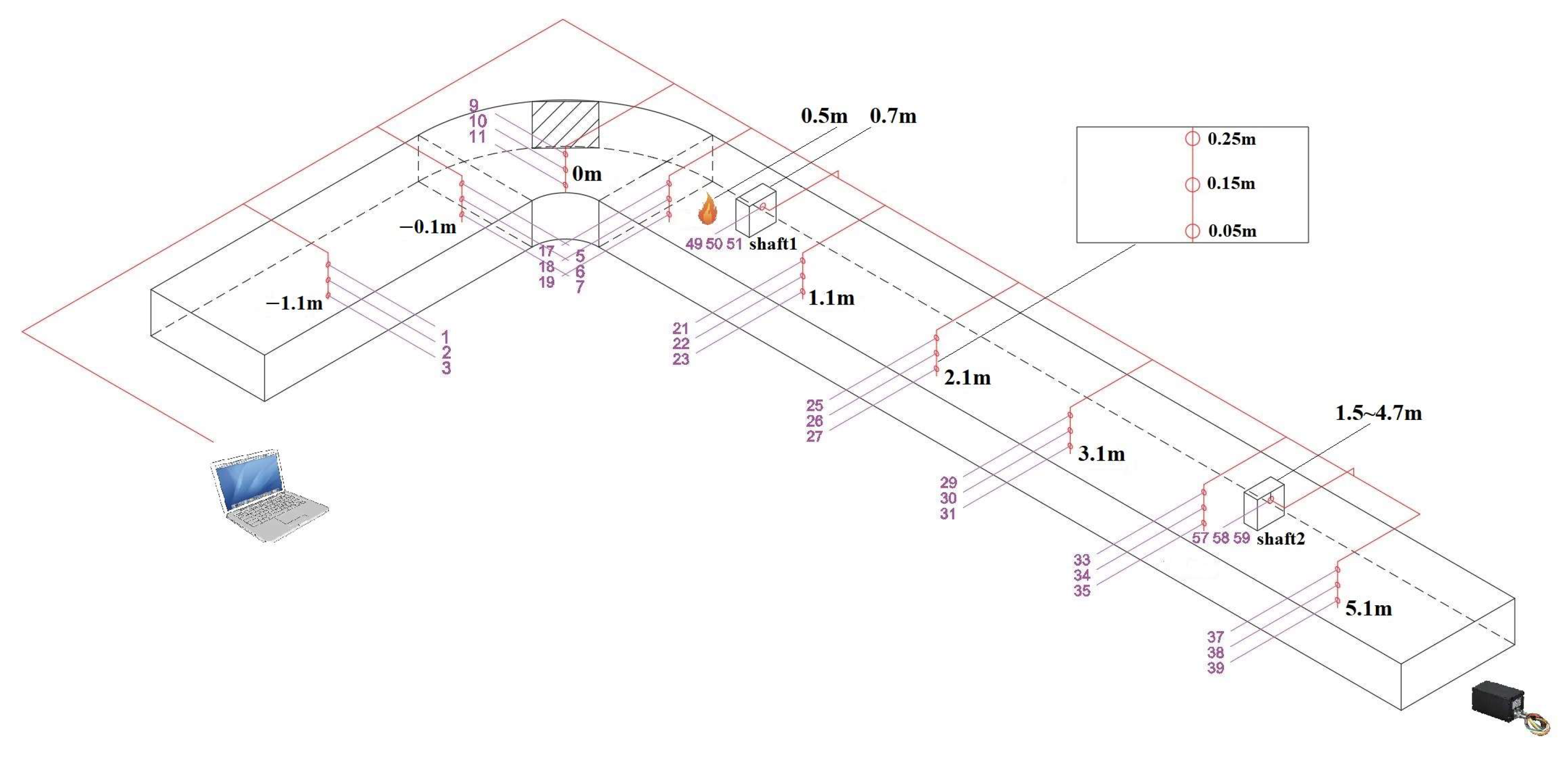
2.1. Design of UTLT Smoke Control Experimental Platform

The UTLT smoke control experimental platform was constructed based on Froude’s similarity principle to study the influence of different smoke vent settings on the smoke exhaust effect. For actual fires in real tunnels, a 2.5 MW fire was taken as an example; the spread and diffusion of smoke mainly depends on the buoyancy driven by the heat of the fire source; and the characteristic smoke velocity can be obtained using the following equation:
u f = 1.9 × ( 0.7 Q c ) 1 / 5 = 1.9 × ( 0.7 × 2500 ) 1 / 5 = 8.45   m · s 1
When using Froude’s similarity simulation, it is not possible to guarantee that the Reynolds numbers of the simulation field and the full-scale experiment are equal. Therefore, the smoke flow needs to be turbulent to minimize this effect. Ingason [16,17,18] found that the flow in the reduced-scale experimental model can reach a turbulent state if the dimensions in all directions are not less than 0.30 m. To ensure that the difference in Reynolds number (Re) between the reduced-scale and the prototype experiments is small, the Re of the fluid flow in the real tunnel and the tunnel model must be in the range of turbulence self-simulation, and the value of Re should be greater than 105. The characteristic smoke velocity of the real tunnel uf = 8.45 m·s−1, kinematic viscosity μ = 1.48 × 10⁻⁵ m2·s−1, and the equivalent diameter of the real tunnel df = 5.32 m; then, the Re of the real tunnel is as follows:
Re = u f d f μ = 8.45 × 5.32 1.48 × 10 5 = 30.26 × 10 5 > 10 5
According to the Froude’s similarity principle,
u f u m = d f d m 1 / 2
where um is the characteristic smoke velocity of the tunnel model, m·s−1; dm is the equivalent diameter of the tunnel model, m. Therefore, the minimum scale ratio is as follows:
u m d f d m 1 / 2 d m d f d m μ = 8.45 × 5.32 d f d m 3 / 2 1.48 × 10 5 > 10 5
d f d m > 1 9.71
Therefore, the tunnel model was constructed on a scale of 1:12, and the Reynolds number was ensured to be in the range of turbulence self-simulation. The main body of the model was made of a steel structure and transparent tempered glass. Considering that the main body of the tunnel was mostly circular and the curved structure has an influence on the spread of smoke and the setup of the exhaust system, a curved section of a real UTLT, consisting of a bend and two straight sections, was selected for the study, with dimensions of 116.8 m (length) × 10.2 m (width) × 3.6 m (height). According to the similarity principle, the smoke control experimental platform has a dimension of 9.72 m (length) × 0.85 m (width) × 0.30 m (height). The experimental platform is shown in Figure 1.
Due to the lack of urban space, the actual UTLT design generally uses smoke exhaust ducts connected to the top smoke vent and exhausts the smoke out of the tunnel by the force of the smoke exhaust fan. In order to facilitate the experimental study, a smoke exhaust shaft was used as a smoke exhaust pipe. The force generated by the stack effect was utilized instead of the force generated by the exhaust fan to simplify the influence of complex factors brought about by the use of mechanical smoke exhaust equipment and to observe the influence of the variables on the flow characteristics of the smoke in the UTLT more clearly.
In the long straight section, there is a 5.0 m (L) × 0.2 m (W) slot at the top of the tunnel, and 6-mm-thick iron plates of varying lengths were added to the slot so that the smoke vent could change position. In order to study the influence of the typical bend structure of UTLTs on smoke exhaust, the fire source and smoke vents were set in the long straight section. While the short straight section has a shorter distance and the bend has a certain blocking effect on the spread of smoke, no smoke vents were set up in this part.
Two smoke vents were set up in the long straight section of the experimental platform. The vents were placed in the slot and they could be moved horizontally within the range of 0 to 5.0 m. By fixing one vent at 0.7 m from the origin and changing the position of the other vent, the intervals of the vents were taken to be 0.8 m, 1.6 m, 2.4 m, 3.2 m, and 4.0 m. The smoke vent’s area was 0.20 m (L) × 0.10 m (W), and the vents were connected to the smoke shaft with a height of 0.40 m.
Nine groups of K-type armored thermocouple trees were set up along the longitudinal axis of the experimental platform, and three thermocouples were arranged vertically in each group of thermocouple trees, with heights of 0.05 m, 0.15 m, and 0.25m. The gas concentration was measured using a highly sensitive portable multi-gas detector, with the range of carbon monoxide (CO) 0~1000 ppm, carbon dioxide (CO2) 0~8000 ppm, and oxygen (O2) volume concentration 0–30% VOL, as well as having an accuracy of 3%. The gas flow rate was measured using a high-temperature tube anemometer composed of a stainless steel tube and a Pitot tube, with a range of 0~10 m·s−1 and an accuracy of 3%, and was installed at the center of the smoke vent. The experimental setup is shown in Figure 2.

2.2. Fire Source

According to Chinese technical specifications for the construction of highway tunnels, small cars have a heat release rate of about 3 to 5 MW. Considering the narrow roads and lower heights of urban underground tunnels, as well as the restriction of large trucks, tanker trucks, and other freight vehicles, three types of fire size corresponding to small and medium-sized sedans were selected: 2.5 MW, 3.5 MW, and 4.5 MW. When determining the location of the fire source, the main consideration was the symmetry of both sides of the bend, and the structure of the bend has a greater impact on the development of the fire, so the source of the fire was set in the position of the long straight section near the bend. Taking the center of the bend section in the UTLT experimental platform as the origin, the fire source was located in the straight line section, 0.5 m away from the origin, as shown in Figure 2. The methanol pool fire is selected as the fire source, and its heat release rate can be calculated using Equation (6).
Q = η fuel · m fuel · S · Δ H r
where Q is the heat release rate of the fire, kW; ηfuel is the combustion efficiency of the fuel; mfuel is the rate of mass loss from combustion per unit area of the fuel, g·m−2·s−1; S is the area of the oil pan, m2; and ΔHr is the heat of combustion of the fuel, kJ·g−1.
According to the results of previous experiments [19], the methanol combustion efficiency ηfuel is about 100%, the mass loss rate per unit area is 0.0016 g·m−2·s−1, and the heat of combustion ΔHr is 20.34 kJ·g−1. From the similarity criterion, it can be concluded that the experimental fire size corresponding to 2.5 MW, 3.5 MW, and 4.5 MW real fires were 5 kW, 7 kW, and 9 kW, and the corresponding oil pan dimensions were calculated as 12.4 cm × 12.4 cm, 14.7 cm × 14.7 cm, and 16.6 cm × 16.6 cm.

3. Analysis of the Influence of Smoke Vent Arrangement on Smoke Exhaust Effect

3.1. Analysis of Smoke Flow Rate in Shafts

Taking the 3.5 MW fire as an example, the smoke flow rates in the two shafts with different intervals are shown in Figure 3. In Figure 3a, it is illustrated that the flow rate of smoke in shaft 1 does not vary with smoke vent intervals, which indicates that the smoke flow rate in shaft 1 is related to the fire size and the distance between the fire source and the smoke vent. In Figure 3b, it takes a longer time for the smoke flow rate curve to stabilize as the distance increases because the stack effect in shaft 2 is weaker, and the smoke flow rate decreases with the increase in distance.

3.2. Analysis of Mass Flow Rate

The calculated results of the average flow rate are shown in Table 1 and Table 2. According to the data, it is understood that the distance between the smoke vents has no significant effect on the smoke flow rate in shaft 1. The average flow rate values are calculated for different fire sizes, which are 0.85 m/s, 1.04 m/s, and 1.13 m/s, respectively, and the mass flow rates of the smoke can be calculated using Equation (7).
m s = A v v s ρ 0 T 0 T S
where Av is the cross-sectional area of the smoke vent, m2; vs is the gas flow rate in the shaft, m/s; T0 is the ambient temperature, K; TS is the temperature inside the shaft, K; and ρ0 is the air density, kg/m3. The mass flow rate of shaft 1 was calculated to be 0.020 kg/s, 0.024 kg/s, and 0.026 kg/s for different fire sizes, respectively. Substituting the data in Table 2 into Equation (7), we obtain the mass flow rates of smoke under different smoke vent intervals and fire sizes, which are shown in Table 3.
In the 3.5 MW fire, the mass flow rates of the smoke in shaft 2 at different locations are shown in Figure 4. With the increase in the distance between the smoke vents, the mass flow rate in Shaft 2 first slightly increases and then decreases. If the smoke exhaust efficiency is a priority, 1.6 m can be chosen as the best distance between the two smoke vents. At this time, the two shafts are closer to the fire source, so the stack effect provides more driving force, and the shafts will not interfere with each other due to the proximity of the two smoke vents.

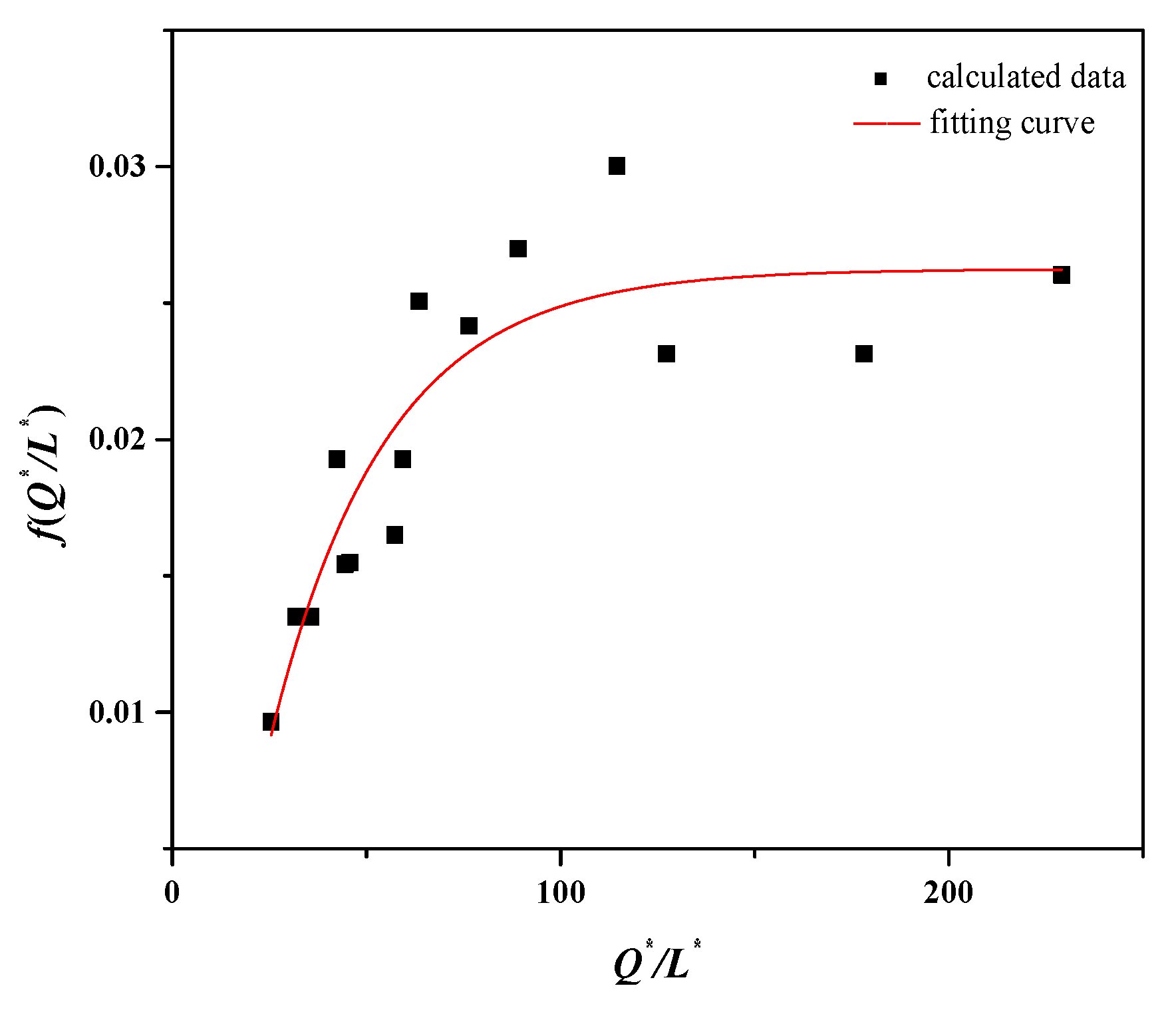
4. Calculating the Model for the Mass Flow Rate of Smoke

From the previous analysis, it is understood that after fixing the position of the fire source, the smoke mass flow rate in shaft 1 does not change with the spacing of the smoke vents, and the smoke mass flow rate in shaft 2 is related to the size of the fire source, the hydraulic height of the tunnel, the distance between the smoke vents, and the tunnel height-to-width ratio. The above physical quantities are selected for magnitude analysis, as shown in Equation (8).
f ( M , L , Q , T 0 , g , C p , ρ 0 , H ¯ , A s ) = 0
where M is the mass flow rate in shaft 2, kg/s; L is the distance between the smoke vents, m; Q is the fire size, kW; g is the acceleration of gravity, m/s2; Cp is the heat capacity of gas, kJ/K; H ¯ is the hydraulic height of the tunnel, m; and As is the tunnel height-to-width ratio. The mass flow rate in shaft 2 is analyzed in a dimensionless manner according to the π theory, a fundamental principle of the method of magnitude analysis, to obtain a simplified equation, as follows:
f ( M ρ 0 g H ¯ 9 , H ¯ L , Q ρ 0 g 3 H ¯ 7 , C p T 0 H ¯ g ) = 0
Simplifying this equation gives the following:
M ρ 0 g H ¯ 9 = f ( A s g 3 H ¯ 9 L , A s g H ¯ Q ρ 0 C p T 0 )
Dimensionless fire size:
Q * = A s g H ¯ Q ρ 0 C p T 0
Dimensionless smoke vent distance:
L * = L A s g 3 H ¯ 9
Equation (10) becomes:
M ρ 0 g H ¯ 5 = f ( Q * L * )
Figure 5 shows the results obtained by substituting the data from Table 3 into Equations (11)–(13).
By fitting the data points to obtain an equation for the mass flow rate in Shaft 2, we obtain the following:
M ρ 0 g H ¯ 5 = 0.03 + 0.04 ( 1 e Q * 30 L * ) + 0.02 ( 1 e 77 Q * L * )
The above equation applies to the approximate calculation of the smoke mass flow rate when the fire source is located upstream of the smoke extraction system in the double-top vents exhaust mode, and the results can be used as a reference for the smoke exhaust system design of UTLTs.

5. Conclusions

The UTLT smoke control platform is built to study the effect of smoke vent interval on the natural smoke extraction effect of vertical shafts through reduced-scale experiments and theoretical analysis, and the conclusions are as follows:
(1)
As the distance between the smoke vents increases, the driving force generated by the stack effect is weakened, leading to a decrease in the smoke exhaust efficiency and a decrease in the smoke mass flow rate.
(2)
Under the experimental condition that the fire source is located near the curved section and the fire size is from 5 to 9 kW, the smoke vent distance of 1.6 m (corresponding to the fire size of 2.5~4.5 MW and the distance of 20 m between the smoke vents in the actual tunnel) has the highest smoke exhaust efficiency.
(3)
A calculation model of the mass flow rate of the smoke vent was obtained through the dimensionless analysis of the mass flow rate in the shaft. The mass flow rate is mainly related to the height of the tunnel, the dimensionless heat release rate of the fire source, and the dimensionless distance between the smoke vents. The model is applicable to natural smoke extraction for small car fires near UTLT bends by double top vents that are located downstream of the fire source.

Author Contributions

Conceptualization: Y.Y. and X.L.; methodology: Y.Y.; software: X.L.; validation: Y.Y. and X.L.; formal analysis: X.L.; investigation: X.L.; resources: Y.Y.; data curation: X.L.; writing—original draft preparation: X.L.; writing—review and editing: X.L.; visualization: X.L.; supervision: Y.Y.; project administration: Y.Y.; funding acquisition: Y.Y. All authors have read and agreed to the published version of the manuscript.

Funding

This research was funded by the Natural Science Foundation of Hebei Province, grant number E2021507005.

Institutional Review Board Statement

Not applicable.

Informed Consent Statement

Not applicable.

Data Availability Statement

The data supporting the reported results are included in the article; further inquiries can be directed to the corresponding author.

Conflicts of Interest

The authors declare no conflicts of interest.

References

  1. Shi, Y.; Qian, S.; Zhao, P.; Guo, P.; Gao, Z. Influence of Smoke Exhaust Volume and Smoke Vent Layout on the Ceiling Centralized Smoke Exhaust Effect in Tunnel Fires. Fire 2024, 7, 78. [Google Scholar] [CrossRef]
  2. Alpert, R. Calculation of response time of ceiling-mounted fire detectors. Fire Technol. 1972, 8, 181–195. [Google Scholar] [CrossRef]
  3. Strang, E.J.; Fernando, H.J.S. Entrainment and mixing in stratified shear flows. J. Fluid Mech. 2001, 428, 349–386. [Google Scholar] [CrossRef]
  4. Kurioka, H.; Oka, Y.; Satoh, H.; Sugawa, O. Fire properties in near field of square fire source with longitudinal ventilation in tunnels. Fire Saf. J. 2003, 38, 319–340. [Google Scholar] [CrossRef]
  5. Viot, J.; Vauquelin, O.; Rhodes, N. Characterisation of the plug-holing phenomenon for the exhausting of a low density gas layer. In Proceedings of the 14th Australasian Fluid Mechanics Conference, Adelaide, Australia, 10–14 December 2001. [Google Scholar]
  6. Yoon, C.H.; Kim, M.S.; Kim, J. The evaluation of natural ventilation pressure in Korean long road tunnels with vertical shafts. Tunn. Undergr. Space Technol. 2006, 21, 472. [Google Scholar] [CrossRef]
  7. Brahim, K.; Zouhaier, M.; Mourad, B.; Belghith, A. Temperature stratification in a road tunnel. Therm. Sci. 2016, 176, 156. [Google Scholar] [CrossRef]
  8. Jiang, X.; Xu, Z.; Huang, Y.; Chen, C.K. Fire ventilation control scheme for traffic link tunnel in Suzhou Railway Station. Sci. Technol. Rev. 2009, 27, 77–82. [Google Scholar] [CrossRef]
  9. Fan, C. Studies on Characteristics of Tunnel Fire Development and Natural Ventilation Mode Using Shafts. Ph.D. Thesis, University of Science and Technology of China, Hefei, China, 2015. [Google Scholar]
  10. Han, J.; Liu, F.; Wang, F.; Liao, S. Full-scale experimental investigation on smoke spreading and thermal characteristic in a transversely ventilated urban traffic link tunnel. Int. J. Therm. Sci. 2021, 170, 107–130. [Google Scholar] [CrossRef]
  11. Lei, P.; Chen, C.; Zhang, Y.; Xu, T.; Sun, H. Experimental study on temperature profile in a branched tunnel fire under natural ventilation considering different fire locations. Int. J. Therm. Sci. 2021, 159, 31–38. [Google Scholar] [CrossRef]
  12. Liu, S. Study on the effect of width and slope of large cross-section tunnel on critical velocity of fire. Therm. Sci. 2024, 28, 1635. [Google Scholar] [CrossRef]
  13. Zhang, S.; Liao, S.; Shi, L.; Lin, B.; Liu, J.; Wang, J. Promotion Effect of Solid Screen on the Smoke Extraction of Vertical Shaft in Urban Road Tunnel Fire. Fire Technol. 2024, 60, 1333–1355. [Google Scholar] [CrossRef]
  14. Li, J.; Li, Y.; Li, J.; Tian, W. A simplified calculation method on the smoke back-layering length and inlet air velocity in a tilted tunnel fire without shaft. Indoor Built Environ. 2022, 32, 274–285. [Google Scholar] [CrossRef]
  15. Guo, J.; Gao, W.; Cai, G.; Liu, Y.; Wen, H. Numerical study on fire-induced smoke temperature characteristics in small curvature radius UTLT-like tunnels under emergency state. Tunn. Undergr. Space Technol. 2022, 127, 104599. [Google Scholar] [CrossRef]
  16. Li, Y.; Lei, B.; Ingason, H. The maximum temperature of buoyancy-driven smoke flow beneath the ceiling in tunnel fires. Fire Saf. J. 2011, 46, 204–210. [Google Scholar] [CrossRef]
  17. Ingason, H.; Lönnermark, A. Heat release rates from heavy goods vehicle trailer fires in tunnels. Fire Saf. J. 2005, 40, 646–668. [Google Scholar] [CrossRef]
  18. Fan, C.G.; Li, Y.Z.; Ingason, H.; Lönnermark, A. Effect of tunnel cross section on gas temperatures and heat fluxes in case of large heat release rate. Appl. Therm. Eng. 2016, 93, 405–415. [Google Scholar] [CrossRef]
  19. Kalsson, B.; Quintiere, J. Enclosure Fire Dynamics, 2nd ed.; CRC Press: Boca Raton, FL, USA, 2022; pp. 41–69. [Google Scholar]
Figure 1. UTLT smoke control experimental platform. (a) Main structure of the platform; (b) internal structure of the platform.
Fire 08 00049 g001
Figure 2. Schematic layout of experimental platform setup.
Fire 08 00049 g002
Figure 3. Q = 3.5 MW, gas flow rate in two shafts with different vent distances. (a) Smoke flow rate versus time in exhaust shaft 1; (b) smoke flow rate versus time in exhaust shaft 2.
Fire 08 00049 g003
Figure 4. Q = 3.5 MW, mass flow rate in shaft 2.
Fire 08 00049 g004
Figure 5. Calculated mass flow rate curve for shaft 2.
Fire 08 00049 g005
Table 1. Average smoke flow rate in shaft 1, m/s.
Distance (m)0.81.62.43.24.0
Fire Size (MW)
2.50.840.860.880.880.79
3.51.051.021.041.090.99
4.51.131.201.191.091.05
Table 2. Average smoke flow rate in shaft 2, m/s.
Distance (m)0.81.62.43.24.0
Fire Size (MW)
2.50.490.530.380.260.20
3.50.550.590.410.320.27
4.50.570.620.490.340.31
Table 3. Mass flow rate of shaft 2 for different fire sizes and distances of smoke vents, 10−3 kg/s.
Distance (m)0.81.62.43.24.0
Fire Size (MW)
2.512131075
3.512141087
4.514161398
Disclaimer/Publisher’s Note: The statements, opinions and data contained in all publications are solely those of the individual author(s) and contributor(s) and not of MDPI and/or the editor(s). MDPI and/or the editor(s) disclaim responsibility for any injury to people or property resulting from any ideas, methods, instructions or products referred to in the content.

