Abstract
Hexafluoroethane and 1,1,1,3,3,3-hexafluoropropane (abbreviated as HFC-236fa and R-116, respectively, referred to as C2F6 and C3H2F6 based on their molecular formulas) were selected as the object to study the corrosion effects of gas fire-extinguishing agents on different metal materials in the storage state. Typical metal materials used in storage containers including 304 stainless steel, Q235 carbon steel, 6061 aluminum alloy, H59 brass, and T2 copper were subjected to full-immersion corrosion experiments under simulated storage conditions with high-pressure and alternating high–low temperature cycles. High-definition cameras, a scanning electron microscope (SEM), high-precision electronic balances, an energy-dispersive spectrometer (EDS), and X-ray photoelectron spectroscopy (XPS) were used to explore the corrosion characteristics. The chemical reactions and mechanisms were analyzed. The results indicate the following: (1) A thin corrosion layer appears on the surface of the metal with varying degrees of severity but low prevalence. (2) The corrosion rates of C2F6 and C3H2F6 were comparable and varied in the following order: 6061 aluminum alloy > Q235 carbon steel > H59 brass > 304 stainless steel > T2 copper. (3) C3H2F6 is slightly higher than C2F6 in all corrosion rate values. (4) The corrosion of metal materials is mainly attributed to the reaction between metal elements and the F-containing groups produced by the cleavage of C2F6 and C3H2F6. The generated metal halides in turn catalyze the cleavage of C2F6 and C3H2F6. This catalytic effect may be positively correlated with the reactivity of the metal element. (5) The higher corrosive activity of C3H2F6 compared to C2F6 is attributed to the ease of C–C bond cleavage, catalyzed by metal halogens. This study provides theoretical insights into the corrosion ability of halogenated alternatives as a replacement for halon-based fire extinguishers.
1. Introduction
Since the promulgation of the Kigali Amendment to the Montreal Protocol on Substances that Deplete the Ozone Layer promulgated in 2016 [1], the search for efficient and environmentally friendly alternatives to halogenated fire extinguishers has become a global hotspot. The influence of various parameters of gas fire-extinguishing agents on their performance is increasingly being studied.
The implementation of the fire-extinguishing ability and other functions of halogenated hydrocarbons largely depends on their halogen release ability. Therefore, from an atomic perspective, the fire-extinguishing ability, corrosion ability, toxicity, and other aspects of halogenated hydrocarbons have atomic-level correlations. Therefore, the study of the corrosion ability of halogenated hydrocarbons is not only a characterization analysis in application, but also a deep exploration of the mechanism of halogenated hydrocarbon gas fire-extinguishing agents at the micro level. In the storage state, halogenated hydrocarbon gas fire-extinguishing agents gradually activate halogen atoms and release them into the environment due to changes in external temperature and thermal motion within their own molecules. However, due to the reactivity of the stored metal, electron shift phenomena inevitably occur between the metal material and the halogen atoms in the negative valence state, causing some metal atoms to ionize and leading to metal corrosion [2,3,4]. Therefore, during the storage stage of gas fire-extinguishing agents, the corrosion of metal materials in storage containers is inevitable. Once corrosion occurs, it will inevitably reduce the safety performance of the storage container, increase the risk of leakage, and more seriously, may endanger the safety of the surrounding environment and personnel. In addition, due to the characteristics of ionization equilibrium, the number of effective molecules in gas fire-extinguishing agents will continuously decrease as corrosion progresses, resulting in a decrease in their fire-extinguishing ability. Due to this consideration, the National Institute of Standards and Technology (NIST) in the United States initiated relevant research projects as early as the 20th century and added metal corrosion resistance to the 12 key performance indicators that need attention to ensure the application performance and storage safety of new gas fire-extinguishing agents [5]. Therefore, studying the corrosiveness of new gas fire-extinguishing agents on metal materials has become an important topic that cannot be ignored.
Considering that the new generation of gas fire-extinguishing agents is still uncertain, as mature gas fire-extinguishing agents that have been used for a long time, hydrofluorocarbon gas fire-extinguishing agents (i.e., HFCs) can still provide more reference value in studying the thermal instability changes in halogenated hydrocarbons and their interactions with materials in the environment. Meanwhile, as the research direction of the new generation of gas fire-extinguishing agents currently focuses on halogenated hydrocarbon substances containing unsaturated bonds, halogenated alkanes can still provide a quantitative basis for studying the impact of unsaturated bonds on the halogen release ability of halogenated hydrocarbons based on factors such as carbon chains and halogens [6]. Therefore, this article selects hexafluoroethane and 1,1,1,3,3,3-hexafluoropropane (hereinafter referred to as C2F6 and C3H2F6 in the form of its molecular formula) as representative HFC gas fire-extinguishing agents with fixed types and quantities of halogen atoms and similar molecular structures for the study of corrosion effects. As efficient refrigerants and etchants, C2F6 and C3H2F6 have been widely used. Due to its excellent ozone layer protection capability (ozone depletion potential, ODP = 0) [7,8] and the fire-extinguishing ability provided by the molecular type and physical properties of its fluorinated compounds (fire-extinguishing concentrations in the methane environment are 5.19% and 6.92%, respectively), the two halogenated hydrocarbons mentioned above are widely used in the field of gas fire-extinguishing agents. Mao et al. [9] studied the fire-extinguishing mechanisms of various fluorinated hydrocarbons, including C2HF5 and C3H2F6, and found that fluorinated hydrocarbons undergo defluorination first with increasing ambient temperature, followed by C-C bond cleavage. During this process, fluorinated free radicals such as •CF3, •CF2, and •CF gradually appear; Dai et al. [10] studied the compatibility of n-pentane and pentafluoropropane (HFC-245fa) with copper and aluminum materials, and the results showed that N-pentane has good compatibility with aluminum and copper, but both copper and aluminum have catalytic effects on the decomposition of n-pentane. The tensile strength of copper and aluminum undergoes significant changes; Brock et al. [11] pointed out that when HFC-236fa is in contact with humans due to its own F content, a small amount is released. Therefore, when humans are in an HFC-236fa environment, anesthesia-like effects such as fatigue, lack of coordination, and reduced physical activity may occur. Lv et al. [12] studied the corrosion reactions of 2-BTP on 304 stainless steel, Q235 carbon steel, 6061 aluminum alloy, H59 brass, and T2 copper under high-pressure, high and low temperature alternating, and fully immersed environments, and confirmed the basic process of corrosion generation; Huang et al. [13] studied the multi-day corrosion effects of Halon 1301 and CF3I on AZ80A magnesium alloy at normal pressure and 25–400 °C. The study showed that as the corrosion deepened, the magnesium alloy gradually changed color and its mechanical properties gradually decreased. Hu et al. [14] studied the corrosion behavior of 60xx aluminum alloy and 304 stainless steel in a thin electrolyte layer and observed that the depth of the corrosion layer gradually increased, forming a protective shell. As mentioned above, previous studies have mainly focused on the corrosion of metal materials by gaseous fire extinguishers under atmospheric/low-pressure conditions and high temperatures, with almost no research revealing the corrosion behavior of gaseous fire extinguishers on metal materials under simulated storage conditions (high-pressure and alternating high and low temperatures). But it is well known that the lifespan of gas fire extinguishers mainly lies in the storage stage before extinguishing the fire. Under storage conditions, high temperature and atmospheric pressure are usually not present. Therefore, the performance of gas fire-extinguishing agents under storage conditions is still in a blank stage. This is also the basis for setting experimental conditions. This study employs a self-constructed experimental platform for evaluating the corrosive characteristics of C2F6 and C3H2F6 on five typical metal materials of storage containers under the conditions of high pressure, alternating high and low temperatures, and complete immersion. This research focuses on characterizing the corrosion morphology, corrosion rate, and corrosion products. The corrosion mechanisms are also analyzed. The findings aim to assess the application feasibility of C2F6 and C3H2F6 and its related hydrofluoroalkyl fire-extinguishing agents.
2. Experimental Materials and Testing Methods
2.1. Experimental Materials
The purity of both C2F6 and C3H2F6 used in the experiment was 99.9%, and they were purchased from Zhejiang Fu Co., Ltd, Hangzhou, China. The molecular structures of C2F6 and C3H2F6 are illustrated in Figure 1, and their physicochemical properties are summarized in Table 1.
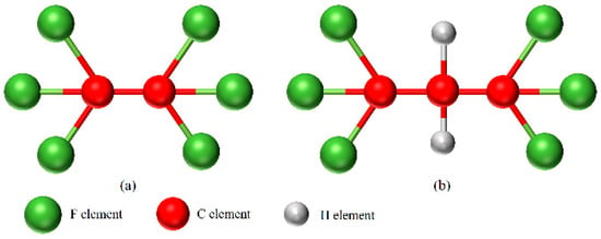
Figure 1.
The molecular structures (a) C2F6; (b) C3H2F6.

Table 1.
Environmental characteristics of C3H2F6 and C2F6 [15,16].
The metal specimens utilized in the experiments included 304 stainless steel sheets (C: 0.06 wt%, Mn: 1.7 wt%, Si: 0.85 wt%, Cr: 11.1 wt%, Ni: 8.6 wt%, Fe: 70.59 wt%), Q235 carbon steel sheets (C: 0.18 wt%, Si: 0.3 wt%, Mn: 0.6 wt%, Fe: 98.92 wt%), 6061 aluminum alloy sheets (Si: 0.61 wt%, Fe: 0.4 wt%, Cu: 0.24 wt%, Mn: 0.14 wt%, Mg: 1.03 wt%, Cr: 0.1 wt%, Zn: 0.05 wt%, Al: 97.43 wt%), H59 brass sheets (Cu: 51.1 wt%, Fe: 0.11 wt%, Zn: 41.69 wt%), and T2 copper sheets (Cu: 99.9 wt%). These five metal materials are representative of those typically used in fire-extinguishing agent storage containers, with their specific applications in such containers detailed in Table 2. The dimensions of the metal sheets were 15 mm × 5 mm × 3 mm (length × width × height), and a through-hole with a diameter of 4 mm was drilled at the center-top of each sheet for suspension within the experimental container, as illustrated in Figure 2. Prior to each experiment, the metal sheets were sequentially polished using 400-grit, 1000-grit, and 2000-grit sandpaper to achieve a smooth and flat surface. Additionally, the small hole sidewalls were smoothed using a grinding rod with a diamond abrasive tip and a sanding wheel with 2000-grit sandpaper attached to an angle grinder. The metal sheets were then weighed using a high-precision electronic balance (SHIMADZU AUW-120D, Shimadzu, Kyoto City, Japan) with an accuracy of 0.01 mg.

Table 2.
Five typical metal materials for storage containers [17,18,19].
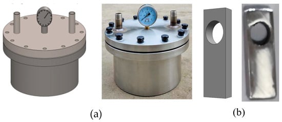
Figure 2.
(a) Corrosion test apparatus; (b) metal sheet appearance diagram.
2.2. Testing Apparatus and Methods
2.2.1. Experimental Apparatus and Steps
The experiment was conducted under the conditions of high pressure, alternating high and low temperatures, and complete immersion. As illustrated in Figure 3, the metal sheet was first placed in the experimental container. The container was then evacuated, followed by the introduction of dry nitrogen to ensure the absence of moisture and air. Subsequently, liquid-phase C2F6 and C3H2F6 (at 25 °C) were pumped into the container using a peristaltic pump until the metal sheets were fully submerged in the fire suppressant. Nitrogen was then added to stabilize the internal pressure at 4.2 MPa (±0.1 MPa). The container was subsequently placed in a programmable constant-temperature and humidity experimental device. This device was programmed to create an alternating high–low temperature environment (50 °C to 0 °C) with a fluctuation range of ±1 °C. Specifically, the temperature was alternated 6 times with a cycle duration of 24 h, totaling 144 h. Finally, the system was maintained at room temperature (25 °C) for an additional 24 h.
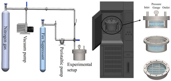
Figure 3.
Experimental devices.
2.2.2. Characterization Methods for Experimental Results
Before the experiment, the metal sheets were ultrasonically cleaned in absolute ethanol, and then they were dried at a constant temperature in a vacuum environment and subsequently weighed [20]. After the corrosion experiment, the corrosion products on the metal sheets needed to be cleaned, and the metal sheets were then weighed after cleaning [21]. The calculation formula for the corrosion rate is as follows [22]:
In the formula, R is the corrosion rate, mm/a; M is the sample mass before the experiment, g; M1 is the sample mass after the experiment, g; M0 is the weight loss of the blank sample, g; S is the total surface area of the sample, cm2; T is the experimental time, h; D is the density of the sample, kg/m3.
The macroscopic morphology of the metal sheet is captured by a camera (Canon EOS 7D, Canon, Tokyo, Japan). The microscopic morphology is monitored by a scanning electron microscope (SEM, TESCAN MIRA LMS 2022, Tescan, Brno, Czech). The corrosion products are characterized by an energy-dispersive spectrometer (EDS, Quantax 200 XFlash 660, Bruker, Brookmire, Germany), X-ray photoelectron spectroscopy (XPS, Thermo SCIENTIFIC Nexsa, Thermo Fisher, Waltham, MA, USA, Step size 0.05–1 eV, conduction energy 20–100 eV, scanning spot size 500 um), and electron paramagnetic resonance (EPR, Bruker EMX spectrometer (EMXplus-9.5/12), Bruker, Brookmire, Germany).
3. Results and Discussion
3.1. Corrosion Rate
Based on the weight changes in each metal sheet before and after corrosion, combined with Formula (1), the corrosion rate of each metal sheet in the experiment can be obtained. The weight change data and corrosion rate are shown in Table 3 and Table 4.

Table 3.
The corrosion rates of five metal plates in experiment C2F6.

Table 4.
The corrosion rates of five metal plates in experiment C3H2F6.
Figure 4 illustrates the magnitude of the corrosion rate of C2F6 and C3H2F6. From the graph, it can be seen that for C2F6, the order of the corrosion rates is as follows: 6061 aluminum alloy > Q235 carbon steel > H59 brass > 304 stainless steel > T2 copper. For C3H2F6, the corrosion rate is completely consistent with the results obtained in the C2F6 experiment with only a slight increase in the overall numerical values.
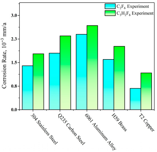
Figure 4.
Corrosion rate of five types of metal sheets.
In addition, the corrosion rate of C3H2F6 is higher obviously for all five types of metal sheets compared to C2F6. It undoubtedly reveals that even if the number of halogen atoms does not differ, there will still be significant differences in the corrosion ability between different molecules. Due to the positive valence of both C and H atoms after dissociation, the occurrence of corrosion depends entirely on the interaction between F ions and metal atoms [23]. Considering that the molecular structures of the two substances are almost identical and there is almost no difference in the composition of elements that affect molecular cleavage [24,25], it can be inferred that the molecular • CH2 group is the main reason for the difference in the regular halogen release ability (manifested as corrosive ability) between the two halogenated hydrocarbons.
3.2. Corrosion Morphology and Element Analysis
3.2.1. Macroscopic Morphology
As shown in Figure 5, neither C2F6 nor C3H2F6 caused significant visible corrosion to the metal sheets after completing the corrosion process. The surface of stainless steel and carbon steel sheets only showed mottled phenomena at some points, which confirms the occurrence of corrosion, but the degree is relatively mild. After experiments with aluminum alloy, brass, and copper sheets, only small black marks were observed on the surface of the copper sheet, while the surfaces of the other two metal sheets are only slightly dull in color. There are no obvious corrosion marks such as corrosion pits on the surfaces of the three metal sheets, indicating that there is no serious corrosion phenomenon. Based on the above phenomenon, it can be seen that under the experimental conditions, the five metal materials exhibit good compatibility with the two corrosive media.

Figure 5.
Metal sheet diagram before corrosion experiment and after C3H2F6/C2F6 experiments: (a) 304 stainless steel; (b) Q235 carbon steel; (c) 6061 aluminum alloy; (d) H59 brass; (e) T2 copper.
3.2.2. Microscopic Morphology and Element Analysis
- (1)
- SEM + EDS results of 304 stainless steel sheets
In Figure 6, it can be observed that there is a less obvious accumulation of corrosion products in the corrosion product area defined by the white coil (hereinafter referred to as the “delineated area”), and the accumulated corrosion products are in the form of shallow flakes. In Figure 6b, the C element also exhibits aggregation in the delineated area, and the aggregation pattern of the C element is basically consistent with that of the corrosion products. In Figure 6c, it can be observed that the F element exists in a point-like cluster on the entire metal surface, but shows a relatively obvious missing state in the delineated area, and the pattern of the missing area overlaps to a large extent with the above clustering pattern. In Figure 6d, there is a significant absence of the Fe element in the upper part of the delineated area, and only sporadic rarefaction is observed in the lower part of the delineated area. The area of Fe element deficiency is also basically consistent with the pattern of the clustering area. Therefore, based on the distribution of the four elements, it can be found that the main component of the corrosion products adsorbed on the surface of 304 stainless steel is non-fluorinated organic compounds, and there are certain binding products of Fe/C/F elements.
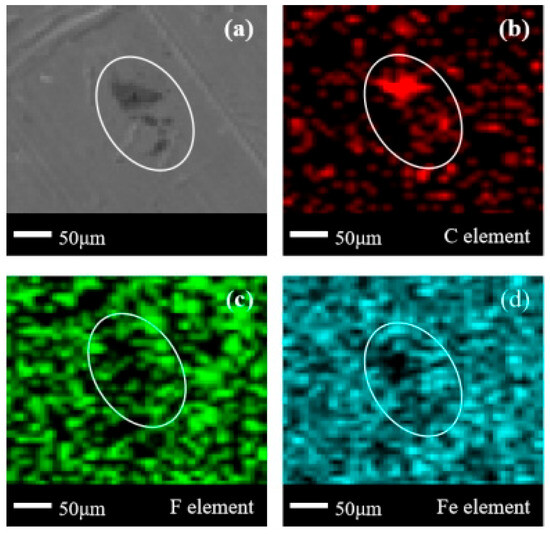
Figure 6.
SEM + EDS results of 304 stainless steel surface after C2F6 corrosion experiment. (a) SEM image at 200× magnification, with (b–d) at the same position; (b) Distribution image of C element; (c) Distribution image of F element; (d) Distribution image of Fe element.
Compared to Figure 6a, the stainless steel surface in Figure 7a adsorbs very obvious corrosion products. In addition to the obvious protrusions in the designated area, there is a shallow sheet-like corrosion product settlement in the lower-right corner of the designated area, similar to the shape shown in Figure 6a. Based on the blank area of the Fe element in Figure 7d, it can be basically determined that there are two forms of corrosion products, one thick and one thin, appearing on the surface of 304 stainless steel. In Figure 7b, there is a certain degree of concentration of the C element in the area where corrosion products exist, but compared to Figure 6b, this aggregation is less obvious. In Figure 7c, there are obvious missing areas of the same shape for element F in the enclosed area, and scattered blank areas appear in the lower-right corner of the enclosed area. From the perspective of the clarity of the edges of the blank area of Fe elements, the absolute majority of the larger corrosion products on the surface of 304 stainless steel in the C3H2F6 experiment are fluorine-free organic compounds, while the majority of the smaller corrosion products are the combined products of Fe/C/F elements. Meanwhile, due to the significant differences in the morphology of corrosion products and corresponding element distributions in Figure 6a and Figure 7a, it can be inferred that the defluorination phenomenon in the C3H2F6 experiment should be more pronounced and the degree of corrosion should be deeper.
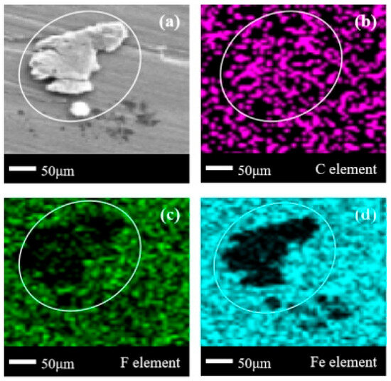
Figure 7.
SEM + EDS results of 304 stainless steel surface after C3H2F6 corrosion experiment. (a) SEM image at 200× magnification, with (b–d) at the same position; (b) Distribution image of C element; (c) Distribution image of F element; (d) Distribution image of Fe element. SEM + EDS results of Q235 carbon steel sheets.
In Figure 8a, the location of the corrosion products is difficult to directly observe. Based on the blank area of the Fe element in Figure 8d, it can be observed that there are extremely shallow sheet-like corrosion products only at the gaps in the raised areas of the metal surface itself. In Figure 8b, there is a concentration of C elements in the designated area, but the distribution of C elements outside the designated area is extremely sparse. This also indicates that there is less organic matter adsorbed on the surface of carbon steel. In Figure 8c, it can be observed that the blank area of the F element not only exists in the enclosed area, but also widely exists outside the enclosed area. This is due to the fact that the difference in corrosion products and corrosion behavior between 304 stainless steel and Q235 carbon steel is generally small when subjected to the same medium of corrosion. Based on the presence of multiple small sporadic blank areas of the Fe element outside the delineated area in Figure 8d and the analysis results of the 304 stainless steel experiment in (1), it can be concluded that there are likely multiple extremely shallow corrosion products on the surface of Q235 carbon steel. The main corrosion products on the surface of Q235 carbon steel are also organic compounds that have undergone defluorination.
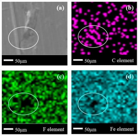
Figure 8.
SEM + EDS results of Q235 carbon steel surface after C2F6 corrosion experiment. (a) SEM image at 200× magnification, with (b–d) at the same position; (b) distribution image of C element; (c) Distribution image of F element; (d) Distribution image of Fe element.
In Figure 9a, it can be seen that more obvious corrosion products exist in the form of blocks and flakes on the metal surface. In the delineated area of Figure 9b–d, the concentration of the C element, the sparsity of the F element, and the blank of the Fe element all appear in the same area. This indicates that the organic compounds that have completed defluorination and those that have not completely defluorined coexist on the metal surface at this time, while the Fe element also exists in the corrosion products. There is a significant difference in the corrosion products in Figure 8 and Figure 9, which once again indicates that the C3H2F6 experiment should have a deeper degree of corrosion on Q235 carbon steel.
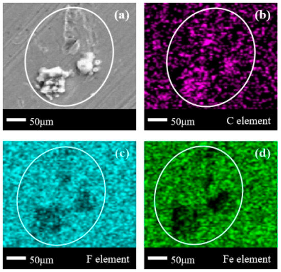
Figure 9.
SEM + EDS results of Q235 carbon steel surface after C3H2F6 corrosion experiment. (a) SEM image at 200× magnification, with (b–d) at the same position; (b) Distribution image of C element; (c) Distribution image of F element; (d) Distribution image of Fe element. SEM + EDS results of 6061 aluminum alloy sheets.
In Figure 10a, a very obvious crack-like corrosion product appears on the metal surface. In Figure 10b, a circle of the C element missing areas appeared on the metal surface, which indicates that the organic matter adsorbed on the surface of 6061 aluminum alloy is as thin as that on the surface of carbon steel, and there is only a less obvious concentration of the C element in the enclosed area. The phenomenon of thinner element distribution also appears in the F element distribution in Figure 10c. However, unlike in (1) and (2), the distribution area of C/F elements in the corrosion products on the surface of aluminum alloys basically overlaps completely, and can be regarded as the main body of the corrosion products being organic compounds containing F elements. This phenomenon is exactly opposite to (1) and (2). Due to the fact that the cracking and reaction of halogenated hydrocarbons are not only influenced by the environment, but also by the catalytic effect of metal ions, it is speculated that this phenomenon is related to the different catalytic effects of different metal elements on the decomposition of C2F6. It is also noted that in the comparison of F element density in Figure 6c, Figure 8c and Figure 10c, the element density in Figure 10c is the lowest. The comparison effect of F element density is more pronounced than that of C element density in Figure 6b, Figure 8b and Figure 10b. This phenomenon to some extent indicates that more C2F6 should have completed defluorination in the corroded area, and the overlap of C/F element distribution indicates that more C2F6 that has not yet participated in the corrosion reaction is adsorbed on the surface of the aluminum alloy.
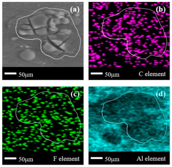
Figure 10.
SEM + EDS results of 6061 aluminum alloy surface after C2F6 corrosion experiment. (a) SEM image at 200× magnification, with (b–d) at the same position; (b) Distribution image of C element; (c) Distribution image of F element; (d) Distribution image of Al element.
In Figure 11a, there are two highly visible clusters of corrosion products in the delineated area (thicker in the upper-right corner and thinner in the lower-left corner). Combining Figure 11b,c, it can be observed that these two corrosion products are organic compounds containing the F element, similar to Figure 10. At this point, the distribution of the Al element in Figure 11d further reveals that larger corrosion products will completely block the metal surface. However, smaller corrosion products are difficult to completely block metal elements, and will only make the Al element at the current position less noticeable. This indicates that in the corrosion products on the surface of aluminum alloys, larger pieces are C/F organic compounds and smaller pieces are compounds containing Al/C/F. Considering again the comparison of the element distribution in Figure 10d and Figure 11d, it is speculated that more F elements were released in the C3H2F6 experiment, promoting the binding of more Al/F elements.
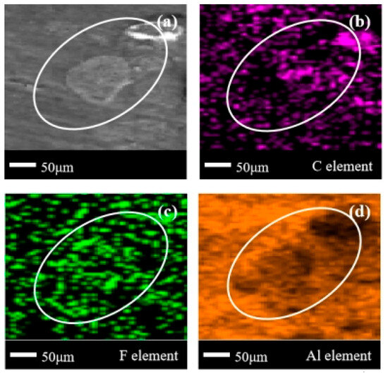
Figure 11.
SEM + EDS results of 6061 aluminum alloy surface after C3H2F6 corrosion experiment. (a) SEM image at 200× magnification, with (b–d) at the same position; (b) Distribution image of C element; (c) Distribution image of F element; (d) Distribution image of Al element.
- (2)
- SEM + EDS results of H59 brass sheets
In Figure 12a, multiple block-shaped corrosion products with clear boundaries appear in the delineated area, forming a clean corrosion product accumulation zone. In Figure 12b,c, the same positions show the clustering of C elements and partial clustering and partial missing of F elements. Comparing the positions of C/F elements, it can be seen that the corrosion products on the surface of brass are a mixture of organic compounds containing F and organic compounds without F. In Figure 12d,e, it can be seen that the missing area of the Cu element basically overlaps with the corrosion product area in Figure 12a, with only a slight fuzzy zone on the left edge. However, according to Figure 12e, there are many element ambiguity zones at the boundary of the missing Zn element zone. Based on this, it can be inferred that on the surface of brass, the combination of the Zn element and C/F element is more extensive compared to the Cu element [26,27]. This is positively correlated with the elemental reactivity of metallic elements.
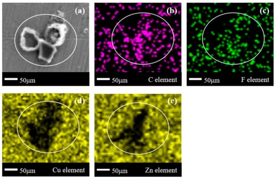
Figure 12.
SEM + EDS results of H59 brass surface after C2F6 corrosion experiment. (a) SEM image at 200× magnification, with (b–e) at the same position; (b) Distribution image of C element; (c) Distribution image of F element; (d) Distribution image of Cu element; (e) Distribution image of Zn element.
In Figure 13a, block-shaped corrosion products with clear boundaries also appear. In Figure 13b, obvious aggregation of C elements can be seen. However, in Figure 13c, most of the delineated area is a region with missing F elements, with only sporadic distribution of F elements in the edge zone. This indicates that the main component of the corrosion products in the C3H2F6 experiment is F-free organic compounds, but there are still F-containing organic compounds present. The distribution of Cu/Zn elements in Figure 13d,e is basically consistent with the phenomenon in Figure 12d,e: Cu elements have larger blank areas, while the blank areas of Zn elements shrink overall compared to the blank areas of Cu elements. According to various phenomena observed in the corrosion experiments of brass with C2F6 and C3H2F6, it can be found that the corrosion products on the metal surface contain both F-containing and F-free organic compounds. This indicates that the defluorination reaction of organic compounds on the metal surface is not uniform, and the defluorination degree of C3H2F6 is higher than that of C2F6. This should be attributed to the fact that brass, as the main metal element inside copper zinc alloys, is composed of active Cu and Zn elements with significant differences. The dissociation difficulty of the F element in C3H2F6 should be lower than that in C2F6, which has been repeatedly confirmed in the analysis of the surfaces of the three metals (1), (2), and (3).
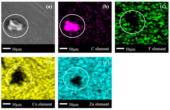
Figure 13.
SEM + EDS results of H59 brass surface after C3H2F6 corrosion experiment. (a) SEM image at 200× magnification, with (b–e) at the same position; (b) Distribution image of C element; (c) Distribution image of F element; (d) Distribution image of Cu element; (e) Distribution image of Zn element.
- (3)
- SEM + EDS results of T2 copper sheets
In Figure 14a, an isolated block-shaped corrosion product appeared on the surface of the copper, and there were no other obvious corrosion products on the metal surface. Based on Figure 14b–d, it can be observed that not only C element aggregation but also F element quota aggregation occurs here. Therefore, it is determined that the main component of the corrosion products on the surface of purple copper is organic compounds containing F, and the internal Cu element composition of the corrosion products is relatively small. Comparing the corrosion product states of C2F6 on brass, it can be found that except for the distribution of element F, the other elements and their distribution states are basically the same. Therefore, it can be inferred that the missing part of the F element in Figure 12b is related to the Zn element, which promotes the dissociation of the C-F bond in C2F6, bringing more free F elements and thinning the F element in the corrosion product aggregation area.
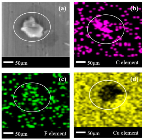
Figure 14.
SEM + EDS results of T2 copper surface after C2F6 corrosion experiment. (a) SEM image at 200× magnification, with (b–d) at the same position; (b) Distribution image of C element; (c) Distribution image of F element; (d) Distribution image of Cu element.
A complex cluster of corrosion products with overlapping sheet-like and block-shaped corrosion products appeared in the central area of Figure 15a, exhibiting different corrosion forms compared to the clearly defined corrosion products in Figure 12a, Figure 13a and Figure 14a. However, similar to Figure 14a, according to Figure 15b,c, it can be seen that the location of the corrosion products here corresponds to the aggregation of C/F elements, indicating that the products present here are still C/F organic compounds. This result is consistent with the various results in Figure 14, but has a higher distribution in terms of the element density of C/F elements than in Figure 14. This can also be confirmed in (1), (2), (3), and (4), which to some extent confirms that the dissociation difficulty of halogen elements in C3H2F6 is lower than that of C2F6. Due to the identical number of halogen atoms between C2F6 and C3H2F6, combined with previous experience, it can be inferred that the increase in the number of H atoms and the C/F ratio reduces the dissociation difficulty of F atoms.
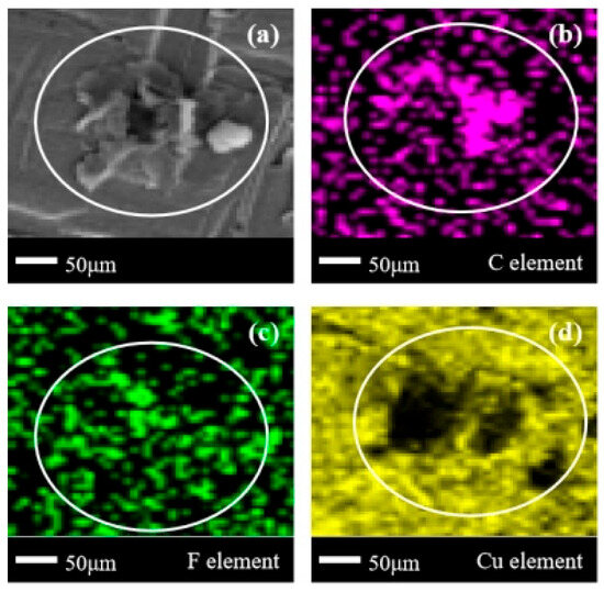
Figure 15.
SEM + EDS results of T2 copper surface after C3H2F6 corrosion experiment. (a) SEM image at 200× magnification, with (b–d) at the same position; (b) Distribution image of C element; (c) Distribution image of F element; (d) Distribution image of Cu element.
3.3. Corrosion Products
Metal Corrosion Products
The corrosive media used in this experiment are C2F6 and C3H2F6 (C/F organic compounds). When reacting with the five metals mentioned above in corrosive media, it can be inferred that the corrosion product containing metal elements should be a metal–F–X (X is an unknown element) compound, as the metals generally only exhibit positive valence, and only F can provide negative valence ions in the two corrosive media. Therefore, after the corrosion experiment, XPS analysis was performed on each metal sheet to obtain the elemental spectrograms of the surface of each metal sheet. By comparing the obtained results with the NIST/XPS database, the corrosion products on the surface of different metal sheets can be obtained.
- (1)
- XPS results of 304 stainless steel sheets
According to the XPS analysis of the Fe element in Figure 16c and Figure 17c, it can be found that the Fe element exists in FeF3 and shows the binding phenomenon of three elements Fe-C-F on the metal surface. Combining the existing forms of element C in Figure 16a and Figure 17a, and comparing them with the element distribution in Figure 6b, it can be inferred that the metal corrosion product FeF3 is widely distributed in the flat areas of the stainless steel plate metal surface. In Figure 16b and Figure 17b, the F element is mainly concentrated in organic compounds, and the F ions combined with Fe ions are not sufficient to exhibit clear peaks.
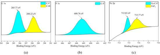
Figure 16.
XPS results of 304 stainless steel sheet surface after C2F6 corrosion experiment. (a) C element peaks; (b) F element peaks; (c) Fe element peaks.
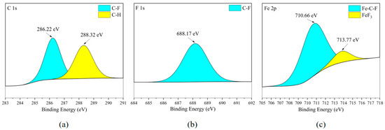
Figure 17.
XPS results of 304 stainless steel sheet surface after C3H2F6 corrosion experiment. (a) C element peaks; (b) F element peaks; (c) Fe element peaks.
- (2)
- XPS results of Q235 carbon steel sheets
According to Figure 18c and Figure 19c, the Fe element on the surface of the carbon steel plate also exists in FeF3, and Figure 18b and Figure 19b confirm the existence of this substance. Meanwhile, based on the fact that the distribution areas of the F and Fe elements in Figure 7c,d almost completely overlap, mainly distributed in the flat areas of the metal surface, it is inferred that the metal corrosion products on the metal surface are mainly FeF3.
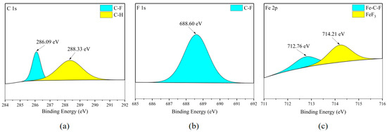
Figure 18.
XPS results of Q235 carbon steel sheet surface after C2F6 corrosion experiment. (a) C element peaks; (b) F element peaks; (c) Fe element peaks.
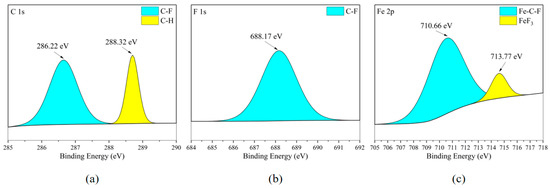
Figure 19.
XPS results of Q235 carbon steel sheet surface after C3H2F6 corrosion experiment. (a) C element peaks; (b) F element peaks; (c) Fe element peaks.
- (3)
- XPS results of 6061 aluminum alloy sheets
According to Figure 20b and Figure 21b, the existence form of the F element in the metal corrosion product AlF3 in can be seen Figure 20c and Figure 21c. Meanwhile, combining Figure 8c,d, it can be observed that the distribution area of the Al element and the distribution area of the F element completely overlap in the flat area of the metal surface, but clear boundary lines appear in the Al element distribution area at the point-/block-like protrusions. Considering that the F element in Figure 20b and Figure 21b mostly exists in the form of C-F bonds, it can be considered that the metal corrosion product on the surface of the aluminum alloy plate is AlF3 and is almost completely distributed in the flat area of the metal surface.
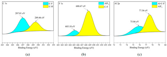
Figure 20.
XPS results of 6061 aluminum alloy sheet surface after C2F6 corrosion experiment. (a) C element peaks; (b) F element peaks; (c) Al element peaks.
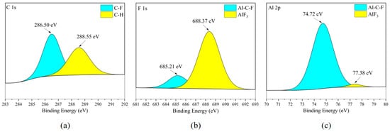
Figure 21.
XPS results of 6061 aluminum alloy sheet surface after C3H2F6 corrosion experiment. (a) C element peaks; (b) F element peaks; (c) Al element peaks.
- (4)
- XPS results of H59 brass sheets
When brass is corroded, there are mainly two types of cations in the metal corrosion products: copper ions and zinc ions [28]. According to Figure 22c,d and Figure 23c,d, both Cu and Zn elements exist in the form of fluoride (CuF2) and ZnF2, but the difference is that Cu and Zn elements also exist in the form of binding with C and F elements. It is worth noting that by combining the SEM analysis of the elemental distribution on the surfaces of different metal plates, it can be inferred that the stronger the reactivity of the metal, the stronger the ability of the metal atoms to promote the cracking of the corrosive medium. By comparing the elements in the organic matter on the surfaces of five metal sheets, it can be found that the organic matter without the F element has a higher content. This proves that the defluorination reaction between C2F6 and C3H2F6 generally occurs on the metal surface. The catalytic cracking effect of metal elements on C-X (X = F, Cl, Br, I) bonds is usually achieved by reducing the reaction energy barrier of chemical bonds. However, the reaction energy barrier of the C-C bond is higher than that of the C-F bond. Therefore, in catalytic reactions, the breakage of C-F bonds occurs earlier and more frequently than the breakage of C-C bonds, resulting in a higher amount of non-fluorinated organic substances on the surface of the metal sheet. However, it needs to be considered that the accumulation of corrosion products will form a passivation layer, hindering the further development of corrosion [29,30]. Therefore, the corrosion rate is not completely consistent with the corrosiveness of the metal itself.

Figure 22.
XPS results of H59 brass sheet surface after C2F6 corrosion experiment. (a) C element peaks; (b) F element peaks; (c) Cu element peaks; (d) Zn element peaks.

Figure 23.
XPS results of H59 brass sheet surface after C3H2F6 corrosion experiment. a: C element peaks; b: F element peaks; c: Cu element peaks; d: Zn element peaks. (a) C element peaks; (b) F element peaks; (c) Cu element peaks; (d) Zn element peaks.
- (5)
- XPS results of T2 copper sheets
According to Figure 24c and Figure 25c, the main form of the Cu element on the surface of the copper sheet is the combination of Cu with C and F elements. Due to the presence of CuF2 in the F element in Figure 24b and Figure 25b, the distribution areas of F and Cu elements in Figure 10a mostly overlap. Therefore, it is inferred that CuF2 exists in the cross-distribution area of Cu and F elements on the metal surface (flat area of the metal surface), but due to its low content, it was not clearly observed during XPS scanning. It is worth noting that the metal reactivity of red copper (Cu: 99.9 wt%) is the lowest among the five metals. In the previous speculation, the reactivity of metals (i.e., the ability of metals to donate electrons) is roughly related to the degree of corrosion. The stronger this ability, the higher the degree of corrosion produced on the metal surface. Based on this inference, the degree of corrosion on the surface of brass should be at a relatively low level. Therefore, this is consistent with the XPS analysis results of the copper sheet surface.

Figure 24.
XPS results of T2 copper sheet surface after C2F6 corrosion experiment. (a) C element peaks; (b) F element peaks; (c) Cu element peaks.
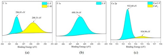
Figure 25.
XPS results of T2 copper sheet surface after C3H2F6 corrosion experiment. (a) C element peaks; (b) F element peaks; (c) Cu element peaks.
Based on the significant difference in C/F element density between the two on the surface of the metal sheet in the above analysis, as well as their overall lower corrosion rate compared to hexafluoropropane, and considering that hexafluoropropane and hexafluoroethane have the same number of -CF3 groups in their molecular structures, and their bond lengths on C-C bonds are equal, bond angles on C-C bonds and F-C-F bonds are equal, and bond energies are similar, it can be concluded that the main difference between the two at the molecular level is that hexafluoropropane has an additional -CH2- group on the second C. It is speculated that in hexafluoropropane and hexafluoroethane, -CH2- as a complete functional group can enhance the instability of halogenated hydrocarbons, enabling them to obtain stronger halogen release ability in alternating thermal environments.
Based on the above results, it can be concluded that there are two types of products on the surface of the metal plate after the corrosion experiment of halogenated hydrocarbons: one is organic attachments, which adhere to the metal surface in the form of generally small-volume point or sheet corrosion products. In this part of the corrosion products, there are often compounds formed by the fusion of metal elements and organic matter; another type is metal halides, usually fluorinated metals. However, compared with halogenated alkenes and fluoroketones with unsaturated bonds, the products observed in the corrosion experiments of halogenated alkanes have a similar composition, but the number and morphology of attachments are not prominent. It can be inferred that the content of metal halides on the metal surface is extremely low, making it difficult to detect the presence of fluorinated metals in XPS analysis (this phenomenon occurs because the content of organic fluorides is overwhelmingly higher than that of metal fluorides).
3.4. Corrosion Mechanism
3.4.1. Chemical Reactions During Corrosion Process
Various products in the experimental environment come from C2F6 and C3H2F6, which gradually appear with the cracking of corrosive media. However, due to the strong stability of alkanes themselves, the cracking process of corrosive products is difficult to observe from a macroscopic perspective. Therefore, obtaining meaningful types of free radicals is very helpful for analyzing possible reactions (as the free radicals in the experimental environment only come from corrosive media, it is possible to know what changes have occurred in the corrosive media during the experiment).
EPR technology is used to characterize the free radical species generated in the gas/liquid residue after corrosion experiments. Different concentrations of residues were introduced into DMPO solution and mixed, and then recorded on a Bruker EMX spectrometer (EMXplus9.5/12). For the detection of free radicals in the residue captured by DMPO, the parameters for C2F6 include the following: X-field scan; the scanning steps are 1000; the starting point is set to 3455.00 G; the center field is 3505.00 G; the scanning width is 100.00 G; and the microwave frequency is 9.85 GHz; a microwave power of 20 mW; the stride is 0.1 G; the convergence time is 60.00 ms; and the power attenuation is 20 dB. The parameters for C3H2F6 include the following: X-field scan; the scanning steps are 1024; the starting point is set to 3444.05 G; the center field is 3489.09 G; the scanning width is 92.53 G; and the microwave frequency is 9.85 GHz; a microwave power of 20 mW; the stride is 0.09 G; the convergence time is 60.00 ms; and the power attenuation is 20 dB. In the analysis results for C2F6, g = 2.00611, LineWidth = 1.46334, and LineShape = 0.0816; in the analysis results for C3H2F6, g = 2.609, LineWidth = 1.72421, and LineShape = 0.9485. After obtaining the analysis results, the Spinfit module in the XENON 1.2 software that comes with BrukerEMXplus was used to analyze and fit the obtained EPR spectra, and the fitting graphs are shown in Figure 26 and Figure 27. The peak shape reveals the presence of •CF3 radicals, but due to the almost identical AH and AN of each carbon radical, it is difficult to effectively distinguish whether the DMPO is connected to a carbon radical in the two research objects. This is reflected in Figure 26 and Figure 27 as an approximation of the peak shape. However, by comparing the LineWidth and LineShape, it is speculated that the free radicals captured in the C3H2F6 experiment are different from those in the C2F6 experiment, and this speculation is made based on the differences in the analyzed objects [31,32].
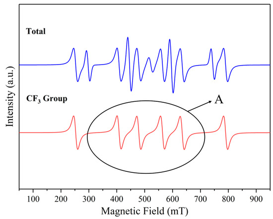
Figure 26.
The presence of major free radicals after C2F6 corrosion experiment. A: Peak of Attention.
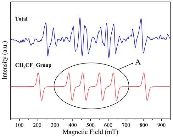
Figure 27.
The presence of major free radicals after C3H2F6 corrosion experiment. A: Peak of Attention.
It can be seen that the • CF3 group appeared in the C2F6 experiment, while the C3H2F6 experiment had C2H2F6 groups. Due to the limitations of EPR, it can be concluded through peak comparison that the probe in Figure 27 recognizes the • CF3 group due to the strong signal of the • CF3 group in the C-related group, which has a high similarity to the peak in Figure 26. However, the gentle gradient slope at position A in Figure 27 proves that these are two similar but not completely identical peaks. Therefore, it is believed that • CF3 and • CH2CF3 groups appeared in the C3H2F6 experiment, but they overlapped during probe recognition.
Meanwhile, using the Gaussian 16W + Gaussian View 6.0 software package combined with B3LYP/6-311++G (d, p) basis group simulation, the important functional group bond energies and minimum reaction energy barriers of C2F6 and C3H2F6 molecules were calculated. This can help us identify possible reaction pathways for free radicals. As shown in Table 5, the C-C bond in C2F6 and C3H2F6 is much more electronegative than the fluorine atom in hydrogen atoms, and the bond energy is slightly lower than that of the C-C bond in standard alkanes (the C-C bond energy in ethane is approximately 376 kJ/mol) [24]. However, the • CF3 group in C2F6 has a slightly weaker C-C bond compared to C3H2F6 due to its stronger electron-withdrawing effect. In both types of compounds, the C-F bond energy is significantly higher than the C-H bond and C-C bond. Therefore, in the early stage of cleavage, • CF3 mainly appears as a complete functional group. In the molecular structure of C2F6’s own perfluorinated substitution, defluorination is more difficult, so the C-F bond energy is slightly higher than that of C3H2F6. Therefore, when the two compounds undergo cleavage, the C-C bond, due to its lowest bond energy, will be the earliest to break and generate • CF3 radicals (path 1 or path 3) or • CF3CH2 radicals (path 3). For C3H2F6, it is more likely to join pathway 4 at the same time as pathway 3 after the C-C bond breaks first; while path 3 continues to occur, path 4 may also proceed synchronously. Comparing paths 5 and 6, the former should occur and release • H radicals earlier. The above process is reflected in Table 6.

Table 5.
The bond energies of each chemical bond in C2F6 and C3H2F6.

Table 6.
Various functional groups and possible generation pathways in C2F6 and C3H2F6.
3.4.2. Corrosion Process
Based on the analysis in the previous sections, it can be concluded that although there are differences in various details during the corrosion process of C3H2F6 and C2F6 on metal materials, the overall corrosion process is generally consistent.
- (a)
- Cracking of C3H2F6/C2F6: in high and low temperature environment, due to the destruction of its own thermal stability, corrosive media undergo trace cracking reactions, resulting in internal C-C, C-F, and C-H bond breakage (due to differences in bond energy, C-C bond breakage occurs earlier, while C-F bond breakage is more difficult), producing functional groups such as • CF3;
- (b)
- Corrosion reaction: Metal plates immersed in corrosive media experience the contact and exchange of metal atoms and halogen-containing groups at the metal corrosion medium contact surface, resulting in the partial dissociation of metal ions on the contact surface. Corrosion phenomenon occurs as follows: for C2F6, metal atom dissociation is more likely due to the reaction between • CF3 and metal atoms; for C3H2F6, the dissociation of metal atoms is due to the interaction between various ionic groups such as • CF3, • H, • F, and metal atoms;
- (c)
- Catalytic cycle: Metal atoms in the ionic state, due to their catalytic effect on molecular dissociation reactions [33,34,35], exhibit cracking catalysis towards the corrosive medium, namely hexafluoroethane/hexafluoropropane, during corrosion, increasing the accumulation of surface corrosion products and accelerating the corrosion reaction. At this time, metal halides and binding products between metal organic compounds (i.e., C-F-M, where M is a metal element) accumulate on the metal surface;
- (d)
- Free radical recombination: Long-term heat exchange can increase the number of free radicals in corrosive media. The collision, recombination, and energy transfer processes between free radicals, between free radicals and molecules, and between free radicals and metal sheets gradually deepen, resulting in a more diverse range of compounds in the environment;
- (e)
- Surface passivation: The corrosive medium itself and its various organic products, metal halides, free functional groups, and other substances gradually accumulate on the surface of the metal sheet. Various shapes of corrosion products, such as dots, blocks, and flakes, combine to form a relatively thin corrosion layer, which slows down the further corrosion of the metal inward in the parts covered by the corrosion layer.
4. Conclusions
In the present study, the corrosion characteristics of C2F6/C3H2F6 on five typical metal materials were performed under simulated storage conditions with high-pressure and alternating high–low temperature cycles. High-definition cameras, SEM, high-precision electronic balances, EDS, and XPS were used to measure the corrosion characteristics. The chemical reactions and mechanisms were analyzed. The following conclusions can be drawn:
- (1)
- Corrosion products mainly exist on the metal surface in the form of extremely small point-like, flake-like, and small-volume block aggregates. Trace amounts of C2F6 and C3H2F6, their decomposition products, metal halides, etc., are also attached to the metal surface.
- (2)
- The corrosion rate ranking of C2F6 and C3H2F6 is as follows: 6061 aluminum alloy > Q235 carbon steel > H59 brass > 304 stainless steel > T2 copper. C3H2F6 is slightly higher than C2F6 in all corrosion rate values.
- (3)
- The corrosion of metal materials is mainly attributed to the interaction between the metal elements and the functional groups containing F produced by the cracking of C2F6 and C3H2F6. The generated metal halides in turn catalyze the cleavage of C2F6 and C3H2F6. This catalytic effect may be positively correlated with the reactivity of the metal element.
- (4)
- The presence of the • CH2 group can enhance the halogen release ability of halogenated alkanes, enabling C3H2F6 with such groups to obtain stronger corrosion resistance.
Author Contributions
Conceptualization, R.C., X.L. and X.H.; Methodology, X.L.; Formal analysis, X.L.; Investigation, X.L. and H.L.; Resources, R.C. and X.H.; Writing—original draft, X.L.; Writing—review & editing, R.C. and X.L.; Funding acquisition, R.C. and X.H. All authors have read and agreed to the published version of the manuscript.
Funding
This work is sponsored by the National Key Research and Development Program of China (2023YFC3010201); the Joint Funds of the National Natural Science Foundation of China (U2133201); and Key Laboratory of Civil Aviation Thermal Hazards Prevention and Emergency Response (No. RZH2023-KF-01).
Data Availability Statement
The original contributions presented in this study are included in the article. Further inquiries can be directed to the corresponding author.
Conflicts of Interest
The authors declare no conflicts of interest.
References
- United Nations Environment Programme. Handbook for the Montreal Protocol on Substances that Deplete the Ozone Layer, 14th ed.; United Nations Environment Programme: Nairobi, Kenya, 2020. [Google Scholar]
- Zhang, H.; Wang, Y.; Wang, X.; Zhou, S.; Yu, R.; Liao, Y.; Li, J.; Tan, Z. Thermal Decomposition Mechanism and Fire-Extinguishing Performance of trans-1,1,1,4,4,4-Hexafluoro-2-butene: A Potential Candidate for Halon Substitutes. J. Phys. Chem. A 2020, 124, 5944–5953. [Google Scholar] [CrossRef]
- Chen, B.; Jin, C.; Yang, J.; Qu, G.; Liu, Y.; Wu, F.; Liu, S.; Liu, X. Synergistic organic manure treatment with Al/Fe/Ca-based fluoride-fixing agents promote soil formation and utilization of phosphate flotation tailings. Process Saf. Environ. Prot. 2024, 192, 495–509. [Google Scholar] [CrossRef]
- Huo, E.; Liu, C.; Xu, X.; Li, Q.; Dang, C. Dissociation mechanisms of HFO-1336mzz(Z) on Cu(1 1 1), Cu(1 1 0) and Cu(1 0 0) surfaces: A density functional theory study. Appl. Surf. Sci. 2018, 443, 389–400. [Google Scholar] [CrossRef]
- Gann, R.G. Next Generation Fire Suppression Technology Program (NGP). In Proceedings of the Halon Options Technical Working Conference, Albuquerque, NM, USA, 27–29 April 1999. [Google Scholar]
- Zhang, W.-B.; Yin, Q.; Liu, M.-R.; Li, C.-Q.; Wang, Z.-C.; Hu, Z.-M. Research on Vaporization and Sudden Cooling Performance of Heptafluoropropane in Prefabricated Fire-Extinguishing Devices Based on Numerical Method. Fire 2025, 8, 124. [Google Scholar] [CrossRef]
- Jiang, Q.; Wang, L. Application of 1,1,1,3,3,3-hexafluoropropane fire extinguishing agent. Chem. Prod. Technol. 2020, 2, 26–31. [Google Scholar]
- Tak, H.W.; Lee, H.J.; Wen, L.; Kang, B.J.; Sung, D.; Bae, J.W.; Kim, D.W.; Lee, W.; Lee, S.B.; Kim, K.; et al. Effect of hydrofluorocarbon structure of C3H2F6 isomers on high aspect ratio etching of silicon oxide. Appl. Surf. Sci. 2022, 600, 154050. [Google Scholar] [CrossRef]
- Mao, A.; Ding, B.; Ding, M.; Yu, H.; Pan, R. Research progress on HF generation and fire extinguishing mechanism during the fire extinguishing process of halogenated fluorinated fire extinguishing agents. Chin. J. Process Eng. 2016, 16, 714–720. [Google Scholar]
- Dai, X.; Shi, L.; An, Q.; Qian, W. Screening of working fluids and metal materials for high temperature organic Rankine cycles by compatibility. J. Renew. Sustain. Energy 2018, 9, 24702. [Google Scholar] [CrossRef]
- Brock, W.J.; Kelly, D.P.; Munley, S.M.; Bentley, K.S.; McGown, K.M.; Valentine, R. Inhalation toxicity and genotoxicity of hydrofluorocarbon (HFC)-236fa and HFC-236ea. Int. J. Toxicol. 2000, 19, 69–83. [Google Scholar] [CrossRef]
- Lv, X.; Liu, H.; Chen, R. Study on the Corrosion Characteristics of Metal Materials in Storage Containers of Typical Hydrobromofluoroalkene Gas Fire Extinguishing Agents in Railway Bus Fire Extinguishing Systems. J. Railw. Sci. Eng. 2025, 22, 3241–3253. [Google Scholar] [CrossRef]
- Huang, X.; Bai, H.; Huo, Y.; Zhou, X. Investigation on the characteristics and mechanism of AZ80A magnesium alloy corrosion by Halon 1301 and CF3I. Aerosp. Traffic Saf. 2024, 1, 73–83. [Google Scholar] [CrossRef]
- Hu, Q.; Zhang, T.; Hu, K.; Chen, S.; Diao, T.; Wang, F. Modeling of Galvanic Corrosion in three-metal Systems Consisting of ZM5 Magnesium Alloy, 6XXX Series Aluminium Alloy and 304 Stainless Steel under Thin Electrolyte Layer by Numerical Simulation, Electrochemical and Salt Spray Test. Int. J. Electrochem. Sci. 2022, 17, 221297. [Google Scholar] [CrossRef]
- Zhu, J.; Hu, J.; Xiao, H.; Yang, L.; Yang, M.; Wang, S.; Zhang, J.; Xing, H. Aluminum-based metal organic frameworks for greenhouse gases CF4 and C2F6 capture with excellent capacity and selectivity. Sep. Purif. Technol. 2024, 331, 125614. [Google Scholar] [CrossRef]
- Pan, J.; Rui, X.; Zhao, X.; Qiu, L. An equation of state for the thermodynamic properties of 1,1,1,3,3,3-hexafluoropropane (HFC-236fa). Fluid Phase Equilibria 2012, 321, 10–16. [Google Scholar] [CrossRef]
- GB 8109-2023; Wheeled Fire Extinguishers. Standards Press of China: Beijing, China, 2023.
- GB 4351-2023; Portable Fire Extinguishers. Standards Press of China: Beijing, China, 2023.
- GB 25972-2024; Gas Fire Extinguishing Systems and Components. Standards Press of China: Beijing, China, 2024.
- GB/T 19291-2003; General Principles for Corrosion of Metals and Alloys. Standards Press of China: Beijing, China, 2016.
- GB/T 16545-2015; Corrosion of Metals and Alloys—Removal of Corrosion Products from Corrosion Test Specimens. Standards Press of China: Beijing, China, 2016.
- JB/T 7901-1999; Uniform Corrosion Immersion Test Method for Metal Materials Laboratory. Standards Press of China: Beijing, China, 2000.
- Liu, Y.; Wu, Y.; Sun, H.; Guo, C.; Wang, J.; Chen, R.; Pan, R. Proactive insights on thermal interactions between textiles and flammable liquids: A comprehensive analysis of thermal characteristics, pyrolysis kinetics and gas emission patterns, using polyamide and diesel as illustrative example. Energy 2025, 320, 135361. [Google Scholar] [CrossRef]
- Yang, Q.; Zhang, J.; Gao, Y.; Zhou, X.; Zhang, H. Toward better Halon substitutes: Effects of H content on pyrolytic and fire-suppressing mechanisms of ozone-friendly fluorinated alkanes. J. Mol. Struct. 2023, 1285, 135506. [Google Scholar] [CrossRef]
- Rahman, P.; Chakraborty, N.; Patel, B.K.; Rajbongshi, K.K. Iodine-Promoted Sulfoximidation of Cinnamic Acids via Oxidative C=C Bond Cleavage. J. Org. Chem. 2024, 89, 10472–10484. [Google Scholar] [CrossRef]
- Lu, J.; Shen, Q.; Fan, R.; Li, G.; Li, Y.; Zhang, X.; Yan, H.; Liu, Y.; Liu, T.; Chen, X. Rational screening of metal single-atom-doped ZSM-5 to promote ring-opening cracking of cycloalkanes to light olefins. Fuel 2025, 381, 133486. [Google Scholar] [CrossRef]
- Pownraj, C.; Karthik, A.; Prabhu, B.; Suresh, S.; Yatish, K.V.; Katiyar, J.K.; Valan Arasu, A. Effect of Cu MOF based functional catalysts on cracking and adsorption of bio-oil compounds via thermo-catalytic pyrolysis: A net zero emission scenario. Fuel 2025, 383, 133871. [Google Scholar] [CrossRef]
- Wang, X.; Su, H.; Xie, Y.; Wang, J.; Feng, C.; Li, D.; Wu, T. Atmospheric corrosion of T2 copper and H62 brass exposed in an urban environment. Mater. Chem. Phys. 2023, 299, 127487. [Google Scholar] [CrossRef]
- Cheng, C.; Le, Q.; Chen, L.; Hu, W.; Wang, T.; Zhu, B.; Zhou, X. Understanding on corrosion mechanism of oxidized AZW800 alloy in 3.5 wt% NaCl solution. J. Magnes. Alloys 2023, 11, 1740–1753. [Google Scholar] [CrossRef]
- Chen, Y.; Guan, J.; Chen, Z.; Fan, H.; Cao, G.; Wang, Z. Study on the initial corrosion behavior of Q235 steel in high-temperature brine. J. Phys. Conf. Ser. 2025, 3009, 012075. [Google Scholar] [CrossRef]
- Liu, Y.; Wang, J.; Sun, H.; Chen, R.; Xu, Y.; Pan, R. Eco-friendly and high-efficiency Halon replacement fire suppressant: Mechanistic and application insights into the synergistic effects of 2-bromo-3,3,3-trifluoropropene and perfluoro-2-methyl-3-pentanone. Combust. Flame 2025, 279, 114295. [Google Scholar] [CrossRef]
- Żyłka, M.; Cieniek, B.; Skała, P.; Żyłka, W.; Stefaniuk, I. Assessment of polyurethane seal degradation in pneumatic drives using EPR and SEM techniques. Measurement 2026, 257, 118614. [Google Scholar] [CrossRef]
- Irriyanto, M.Z.; Li, H.-S.; Choi, B.-S.; Myint, A.A.; Kim, J. Material stability assessment of R-1234ze(E) as a working fluid for supercritical organic Rankine cycle. J. Ind. Eng. Chem. 2021, 96, 169–182. [Google Scholar] [CrossRef]
- Andrew Swamidoss, C.M.; Sheraz, M.; Anus, A.; Jeong, S.; Park, Y.-K.; Kim, Y.-M.; Kim, S. Effect of Mg/Al2O3 and Calcination Temperature on the Catalytic Decomposition of HFC-134a. Catalysts 2019, 9, 270. [Google Scholar] [CrossRef]
- Fang, X.-X.; Liao, W.-M.; Song, J.-D.; Jia, W.-Z.; Wang, Y.; Lu, J.-Q.; Luo, M.-F. Effect of Fe promotion on the performance of V2O5/MgF2 catalysts for gas-phase dehydrofluorination of 1,1,1,3,3-pentafluoropropane. Appl. Surf. Sci. 2019, 490, 365–371. [Google Scholar] [CrossRef]
Disclaimer/Publisher’s Note: The statements, opinions and data contained in all publications are solely those of the individual author(s) and contributor(s) and not of MDPI and/or the editor(s). MDPI and/or the editor(s) disclaim responsibility for any injury to people or property resulting from any ideas, methods, instructions or products referred to in the content. |
© 2025 by the authors. Licensee MDPI, Basel, Switzerland. This article is an open access article distributed under the terms and conditions of the Creative Commons Attribution (CC BY) license (https://creativecommons.org/licenses/by/4.0/).