Article

Fire Performances of SFRC-Insulated Panels and Slabs for Modular Construction: An Experimental Study

by
Sannem Ahmed Salim Landry Sawadogo
1,*,
Tan-Trung Bui
1,
Abdelkrim Bennani
2,
David Damichey
3 and
Ali Limam
1,*
1
MATEIS, CNRS, INSA-Lyon, University of Lyon, UMR 5510, 69100 Villeurbanne, France
2
InPACT Institute, HEPIA Geneva, University of Applied Sciences and Arts Western Switzerland, 1202 Geneva, Switzerland
3
CUBIK-HOME, 58470 Magny-Cours, France
*
Authors to whom correspondence should be addressed.
Fire 2025, 8(12), 458; https://doi.org/10.3390/fire8120458
Submission received: 20 October 2025 / Revised: 15 November 2025 / Accepted: 25 November 2025 / Published: 27 November 2025

Abstract

Fire safety is a crucial issue for buildings, especially with the rise of modular construction, which demands materials that combine lightness with mechanical performance and stability. This study investigates a new concept for single-story modular constructions, made up of 3D cells assembled from thermally and acoustically pre-insulated concrete panels. These panels comprising four walls and two slabs forming the module, are stiffened, with thicknesses of only 5 cm for the walls and 7 cm for the slabs. Their constituent material is a self-compacting, high-volume steel-fiber concrete, containing 80 kg/m3 of steel fibers and 0.3 kg/m3 of polypropylene fibers. Experimental tests on a full-scale wall and slab revealed that adding 0.3 kg/m3 of polypropylene fibers effectively prevents concrete from splintering and achieves the necessary 30 min fire resistance. Standardized full-scale fire tests on walls and slabs confirmed that these thin structures meet fire resistance, insulation, and airtightness standards. The high volume of steel fibers provides ductility, maintaining structural integrity despite concrete spalling. The maximum spalling depth observed in some areas ranged 35 to 50 mm, without compromising structural performance. Overall, the modular system satisfies the fire safety requirements for structural stability (no collapse) and performance in single-story modular construction.

1. Introduction

Modular construction is experiencing rapid growth in the building sector, driven by the need for industrialization as well as increasing demands for efficiency and sustainability. This method, which involves assembling prefabricated components into modules in a factory setting and enables optimization throughout the entire process, from the design to the production phase, from transport to commissioning, and from deconstruction to reuse. It is a key element of the circular economy. Chen et al. (2024) [1] examined the impact of modular construction and low-carbon concrete in the context of a circular economy. Life-cycle analysis revealed that the use of high-performance concrete is economically viable in the long term. The authors also found that the lifespan of modules can be extended from 50 to 150 years, leading to durability improvements of up to 20% per year. Transport costs can be reduced by 30% to 15% through weight reduction in materials. Off-site construction using concrete as the primary material requires relatively thin structural elements to drastically reduce weight and thus transport costs. However, this approach leaves little room for maneuver, as the thickness of the concrete directly affects fire-resistance design [2,3,4]. Recent studies on slender composite columns have highlighted the challenges of ensuring fire resistance when structural thickness is minimized. Lyu et al. (2025) [5] investigated the post-fire behavior of concrete-filled thin-walled steel tubular columns and demonstrated that internal reinforcement significantly improves thermal stability and mechanical performance after fire exposure. Although their work focused on steel–concrete composite systems, the findings underscore the importance of tailored reinforcement strategies in thin structural elements, particularly when conventional reinforcement is reduced or removed. Currently, the most widespread technique to improve the fire resistance is the addition of a sufficient quantity of polypropylene microfibers (PPF) to prevent concrete spalling, without reducing the structural thickness. These plastic fibers melt at around 160 °C, creating decompression channels within the cement matrix. This reduces internal pressure caused by water vapor and limits the risk of explosive spalling when concrete is exposed to fire. Eurocode 2 recommends a PPF dosage of 2 kg/m3 [2], but does not specify fiber dimensions. Nevertheless, several studies on PPF [6,7,8,9] have demonstrated that fiber length has a greater impact on the fire resistance than fiber diameter. The effectiveness of the fibers mainly depends on the number and connectivity of the pores formed when the fibers melt. Water vapor transport, which occurs mainly between 200 and 250 °C, relies on the connectivity of this pore network. Heo et al. 2012 [6] found that, for the same volume fraction, 19 mm PPFs provided better results than 12 mm fibers at temperatures below 250 °C. However, this difference becomes less significant when the exposure temperature exceeds 500 °C, as heat-induced microcracking in the concrete increases the connectivity of the pores created by the melting fibers. These are the key factors influencing the water vapor permeability of concrete [10,11,12]. Zeiml et al. 2006 [13] observed that the vapour permeability of concrete containing 1.5 kg/m3 of 6 mm-long PPF was three to four times higher than that of plain concrete, significantly reducing the risk of spalling. Thus, spalling depth is largely dependent upon fiber length and dosage. In practice, the use of such fibers to improve the fire resistance is common in underground structures, such as tunnels or galleries, made with shotcrete or precast concrete [13,14,15,16]. However, in the building sector, few studies address fire-design requirements for concrete structures incorporating both high volumes of steel fibers, SF, (VSF ≥ 1.0%) and PPF. Studies [17,18,19] have shown that the PPF content recommended by the Eurocode is unnecessary for achieving better fire performance. McNamee et al. (2021) [19] tested reinforced concrete (RC) slabs measuring 1.2 × 1.5 m with thicknesses between 20 and 30 cm, and demonstrated that adding only 0.6 kg/m3 of PPF reduced spalling depth from 10 cm to less than 2 cm. It is, however, important to note that self-compacting concrete (SCC), due to its low porosity and compactness, tends to be more vulnerable to spalling than conventional concrete, as highlighted by some studies [20,21]. In view of the demonstrated effectiveness of PPFs in enhancing the fire performance of concrete, it is essential to evaluate whether stiffened thin panels in which the traditional reinforcement net was completely removed, composed of self-compacting concrete, as employed in modular housing applications, can satisfy the prescribed fire-resistance requirement without experiencing explosive spalling. This study aims to demonstrate that a low dosage of short PPFs, (6 mm for a content of 0.3 kg/m3) is sufficient to achieve this performance. Studies of this kind remain largely unexplored in the literature. The innovative modular concept studied here aims at the construction of detached and terraced two-story houses with a total height below 8 m (Figure 1).
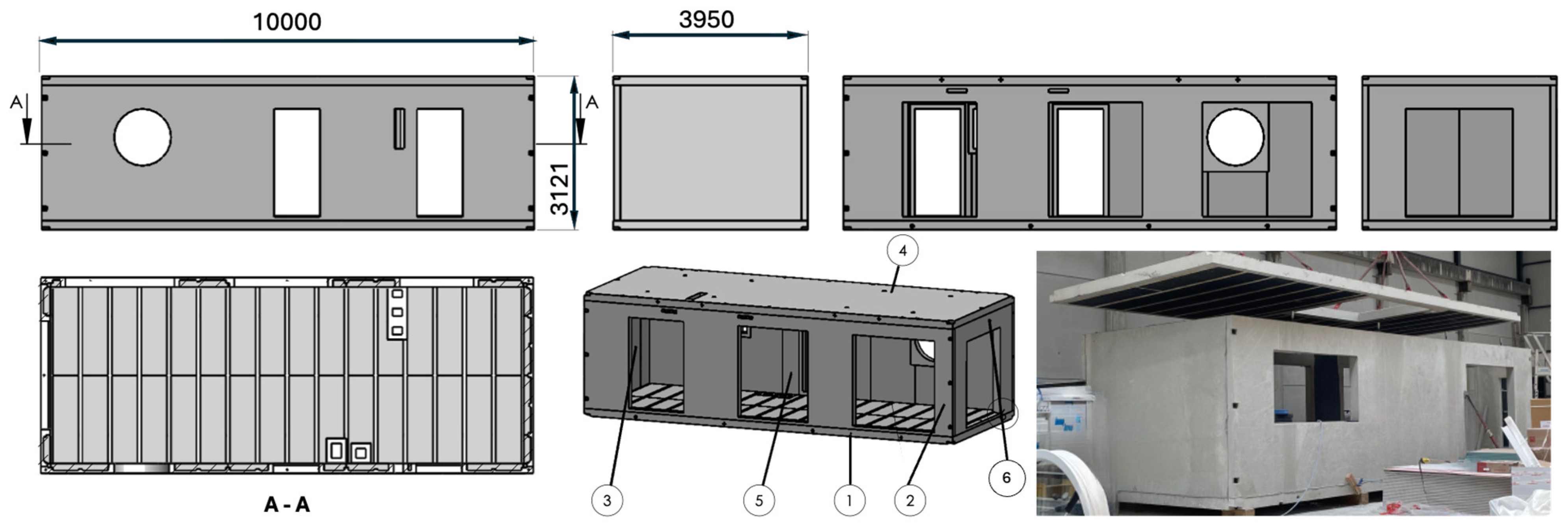
The house is made up of juxtaposed and superimposed 3D modules, anchored to an RC beam foundation and joined together with steel plates. The largest module measures 10 m in length, 4 m in width, and 3.12 m in height. Each module or 3D cell is assembled from concrete panels (four 5 cm thick stiffened walls and two 7 cm thick stiffened slabs), which are thermally and acoustically pre-insulated. These panels are produced by casting Polypropylene fiber and Steel Fiber-Reinforced Concrete (PP-SFRC) directly onto expanded polystyrene (EPS) insulation, which acts as permanent formwork [22]. Following the bolted assembly of the panels (Figure 2), the module is more than 90% factory finished (including electrical systems, plumbing, and plastering) before being transported to the construction site for final assembly. The structural performance of the panels forming the module has been validated elsewhere [22]. This study focuses on the fire behavior of these elements: a wall and a slab, both considered on a representative scale. In France, the regulatory fire-resistance requirement (REI) for an isolated individual house of this type is 30 min. The tests were carried out by the Centre for Studies and Research of the Concrete Industry (CERIB), accredited to carry out standardized fire tests.

2. Materials Properties

The self-compacting fiber-reinforced concrete (SC-FRC) used in this study is a C60/75 class. A hybrid fiber blend has been selected (see Table 1) consisting of a volume fraction of steel fibers VSF = 1% with polypropylene fibers VPPF = 0.033%. The high SF content (80 kg/m3) aims to enhance the ductility of the concrete, while the small quantity of PPF (0.3 kg/m3) is intended to improve the fire performance without compromising the self-compacting properties of the mixture. Although the workability of concrete fundamentally depends on its mix design, short fibers show better dispersibility within the cement matrix compared to the long fibers, thereby ensuring favorable rheological properties of the concrete [23,24]. Xia et al. (2025) [25] recently confirmed that concrete fluidity is affected by both the length and the dosage of PPFs (Figure 3). At 0.9% fiber content, flow spread decreased by 23.6%, 29.1%, and 34.1% for fiber lengths of 6, 12, and 18 mm, respectively, due to increased cement paste demand. A 6 mm fiber length was adopted to comply with flowability criteria for self-compacting concrete. Binders such as fly ash and ground granulated blast furnace slag can be used to replace Portland cement, thus reducing the carbon footprint. In this case, a CEM III/A 52.5 R CP1 cement was used, enriched with limestone filler to improve matrix cohesion, reduce cost, and enhance environmental performance. The maximum aggregate size is 10 mm, which is approximately 3.5 times smaller than the length of an SF. The mix’s flowability is improved by adding a superplasticizer, enabling the concrete to reach very high mechanical strengths in both the short and long term. Tests carried out on concrete specimens at 28 days, 2 months, 3 months, and 6 months demonstrated that the mechanical properties continue to improve significantly beyond the conventional 28-day threshold (Table 2). In 3-point bending tests on 70 mm × 70 mm × 280 mm prisms, the average cracking strength reached 7.69 MPa at 2 months, then 8.61 MPa at 3 months, an improvement of around 12%. Splitting tensile strength, measured on 110 mm × 220 mm cylinders, increased from 7.20 MPa at one month to 8.74 MPa at 2 months, corresponding to a relative gain of 21%. Furthermore, the compressive strength was found to be 58.6 MPa at 28 days, 76.5 MPa at four months (at the time of the wall fire test) and 78.9 MPa at six months (at the time of the slab fire test). This represents improvements of 30% and 34%, respectively, compared to the 28-day strength. This evolution of the mechanical characteristics beyond the classic threshold of 28 days, a threshold supposed to reflect a stabilization of the characteristics, is consistent with findings from other studies on similar concretes using CEM III-type [26,27]. The modulus of elasticity measured at 28 days was 35.2 GPa, and the concrete’s density at the time of testing was approximately 2400 kg/m3.

3. Relevance of Preliminary Small-Scale Fire Tests

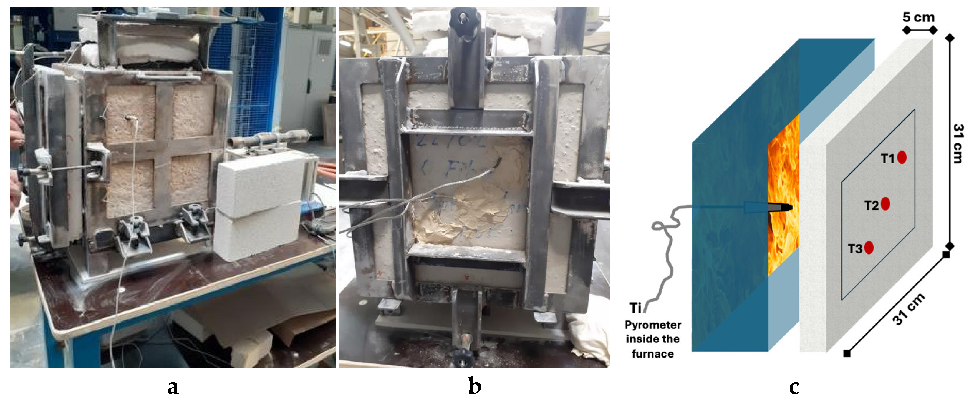
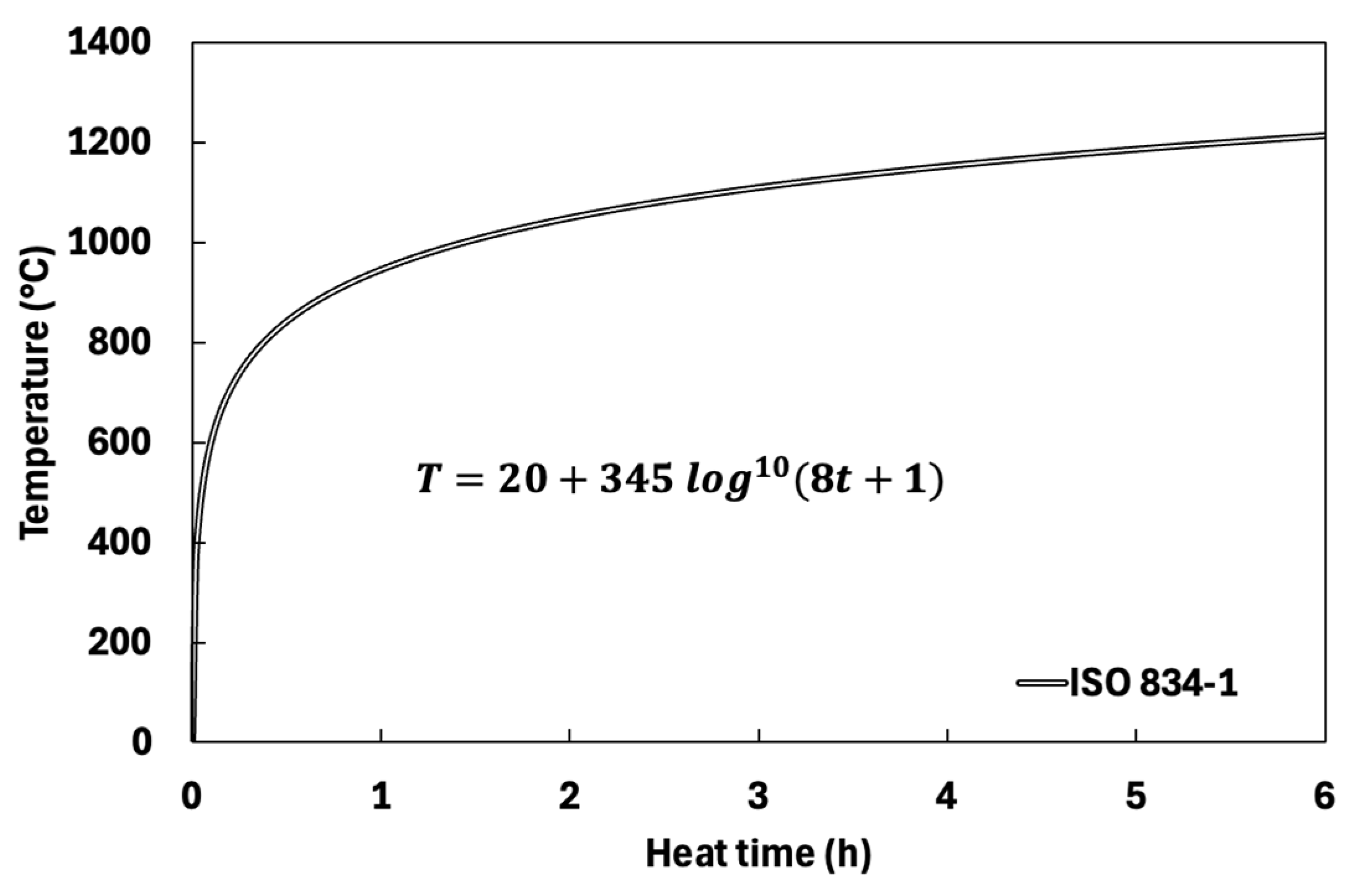
Some concretes are prone to violent spalling when subjected to a high temperature gradient. This phenomenon depends on the concrete’s porosity, its moisture content at the time of testing, and the applied temperature gradient (the rate of temperature change over time). Prior to the full-scale fire experiments, small-scale screening tests were conducted to assess the spalling sensitivity of the developed SC-FRC mix. These tests were essential to validate the suitability of the selected low-dosage PPF strategy and to ensure safe testing conditions for the large-scale specimens. To assess whether the SFRC developed in this study exhibits explosive behavior when exposed to high temperatures, specific tests, described in the following section, have been designed [28]. These tests were conducted on small-scale slabs with sufficiently representative dimensions (310 mm × 310 mm × 50 mm). The thickness of the actual structural element was preserved to accurately reflect the thermal gradient through the depth. The other two dimensions ensure the three-dimensional nature of the thermal and mechanical response, while remaining relatively small compared to the full-scale structure. The recommendations of RILEM TC 256-SPF [29,30] highlights the feasibility of screening tests on small-scale elements (with lateral dimensions of approximately 40 cm) to qualitatively evaluate the fire performance of structural concrete. The tests presented here predate that publication. In this study, the slab which have been selected have lateral dimensions of 310 mm, which is close to the suggested scale [30]. According to the RILEM TC 256-SPF recommendation [30], the minimum specimen thickness should be 300 mm when no mechanical load is applied during the test, and 150 mm when the specimen is loaded. The test must also be conducted for at least 30 min under thermal load. In this study [28], the specimen has a thickness of only 50 mm and is not mechanically loaded, which is six times thinner than the recommended minimum, but fully representative of the real structure being assessed for fire performance. The fire test involved applying the ISO 834-1 fire curve [31], a standard temperature-time function, to one face of the small slab specimen.
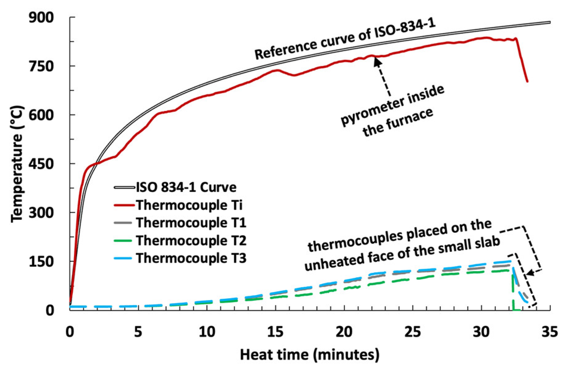
A pyrometer (Ti), inside the designed oven allows to control the temperature increase (Figure 4). The slab was equipped mainly with three thermocouples (T1, T2 and T3), positioned on its free side (opposed to the one exposed to fire), one in the center and two along a diagonal’s slab. The P1 slab, made of SFRC containing 80 kg/m3 of metallic fibers and without PP fibers, underwent a natural drying for 15 days (reaching ∆m/mo = 2.5%, mass variation on initial mass, corresponding to a water loss of 26.08% of the initial water content). This was followed by controlled oven-drying, alternating between 80 °C and 60 °C for 12 days. At the end of this process, the relative mass loss reached ∆m/mo = 6.1%, corresponding to a final moisture content of 3.78% prior to testing. At t = 15 min the temperature at the extrados is clearly below 100 °C (see Figure 5) and there is no sign of damage (no cracking, no spalling). At t = 32 min an explosion occurs which reflects the ejection of a certain thickness of concrete (spalling) on the free surface side, subjected to the ambient environment (Figure 6a). The second test was conducted on the P2 slab with 0.3 kg/m3 of PPF (Table 3). The preliminary drying of the slab is carried out at ambient temperature and reaches approximately 4.25% after 3 months. If we consider that the initial water content was of the order of 9.8% (value corresponding to an average over the various batches), this slab therefore has a drying corresponding to a residual water content of 5.5%, above the 3% representing the non-spalling threshold generally defined by the Eurocode. The thermal loading applied complies with the first test and follows the ISO 834-1 curve [31]. In this case, no spalling is observed up to t = 45 min, the verification of holding for 30 min required by the regulations being largely verified, the test is stopped (Figure 6b). The good performance achieved with a very low dosage of polypropylene fibers (PPF) (0.3 kg/m3) can be explained by several factors. The concrete used is a self-compacting concrete (SCC), which ensures a homogeneous and well-distributed matrix, promoting optimal dispersion of the PPF, which are also short (6 mm instead of the 12–48 mm for classic length of polypropylene fibers) and thus easily distributed uniformly even at low dosages. The rapid melting of these fibers generates pores within the concrete, allowing efficient evacuation of water vapor. The thinness of the manufactured elements (50 to 70 mm) facilitates accelerated thermal conduction and results in a more uniform temperature gradient across the section, thereby limiting localized vapor accumulations and pressure peaks that could cause spalling. Finally, the high content of steel fibers (80 kg/m3) enhances the cohesion and toughness of the concrete, thus improving mechanical resistance against spalling through an internal restraint effect, even though these fibers do not directly increase fire resistance.
Two other tests were conducted on PP-SFRC slabs to confirm the previous result, no spalling after 45 min. While small-scale studies have confirmed the efficiency of PPFs in preventing spalling, it remains unclear whether such findings can be directly extrapolated to full-scale SFRC elements, especially thin, lightly reinforced components that fall outside the scope of current Eurocode guidance. Addressing this scale-up gap is crucial to determine whether a significantly reduced PPF dosage can still guarantee the fire safety at real structural dimensions. Then the concrete formulation, considering 80 kg/m3 of metallic fibers and 0.3 kg/m3 of PP fibers, was adopted for the material constituting the structural elements (slabs and walls) of the module.

4. Test Specimens: Wall and Slab Details

Two structural elements, a wall and a slab (see Table 4), were factory-fabricated in strict accordance with the protocol used for module manufacturing. The wall, 2.74 m high and 3.8 m wide, is only 5 cm thick in the current zone, while the slab, 5.9 m long and 3.9 m wide, is 7 cm thick in the current zone (see Figure 7 and Figure 8). These structures are therefore slender and very thin. No conventional reinforcement is present in the current thickness of either the wall or the slab. The wall’s intermediate stiffeners are 110 mm thick and incorporate HA10 rebar, while the edge stiffeners are 130 mm thick and reinforced with HA12 rebar. The slab’s stiffeners in the current zone are 130 mm thick and reinforced with HA12 rebar, while the thickness of the stiffeners at the edges is 190 mm, reinforced with HA16 rebar. Thermocouples (Tk) are placed inside the stiffeners before the concrete is poured to measure temperature changes during the fire test. M20 and M30 in Figure 7 refer to the anchors installed before casting the concrete for walls and slabs to ensure proper assembly. The KVH timber is solid structural timber used in the stiffeners to support the secondary finishing elements that will be installed later. Since the insulation of the house is installed from the interior, it is difficult to rely directly on the EPS insulation; therefore, mechanically stronger elements such as the KVH timber are required for proper support.

5. Fire Tests

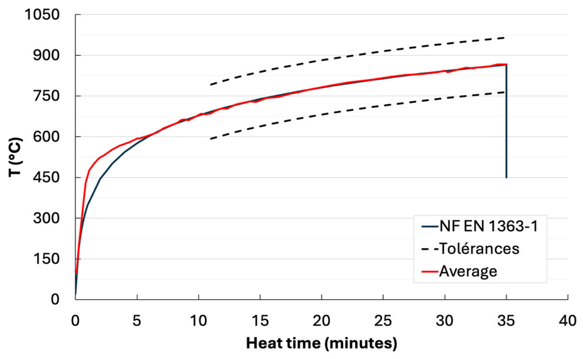
The testing conditions complied with the requirements of EN 1363-1 [32]. The thermal load applied followed the standard fire curve defined in [31] (see Figure 9). The moisture content of the concrete was measured at the time of testing using control specimens (Table 5) which were stored under the same conditions as the test elements. To assess the slab moisture content, six PP-SFRC specimens from the same batch were conditioned to ensure identical curing conditions. Three prismatic specimens (160 × 100 × 130 mm) represented the stiffeners, while three cylindrical specimens (Ø110 × 70 mm) corresponded to the slab’s current zone. The lateral faces were wrapped in aluminum foil to ensure unidirectional drying. Mass was regularly monitored, and moisture content was determined on the test day by oven-drying at 105 °C until the mass variation was below 0.1% over two consecutive 24 h periods. The same protocol was applied to the load-bearing wall control specimens, comprising three specimens (140 × 100 × 110 mm) representing the stiffeners and three specimens (Ø110 × 50 mm) representing the wall’s current zone.

5.1. Stiffened Load-Bearing Wall

5.1.1. Test Description

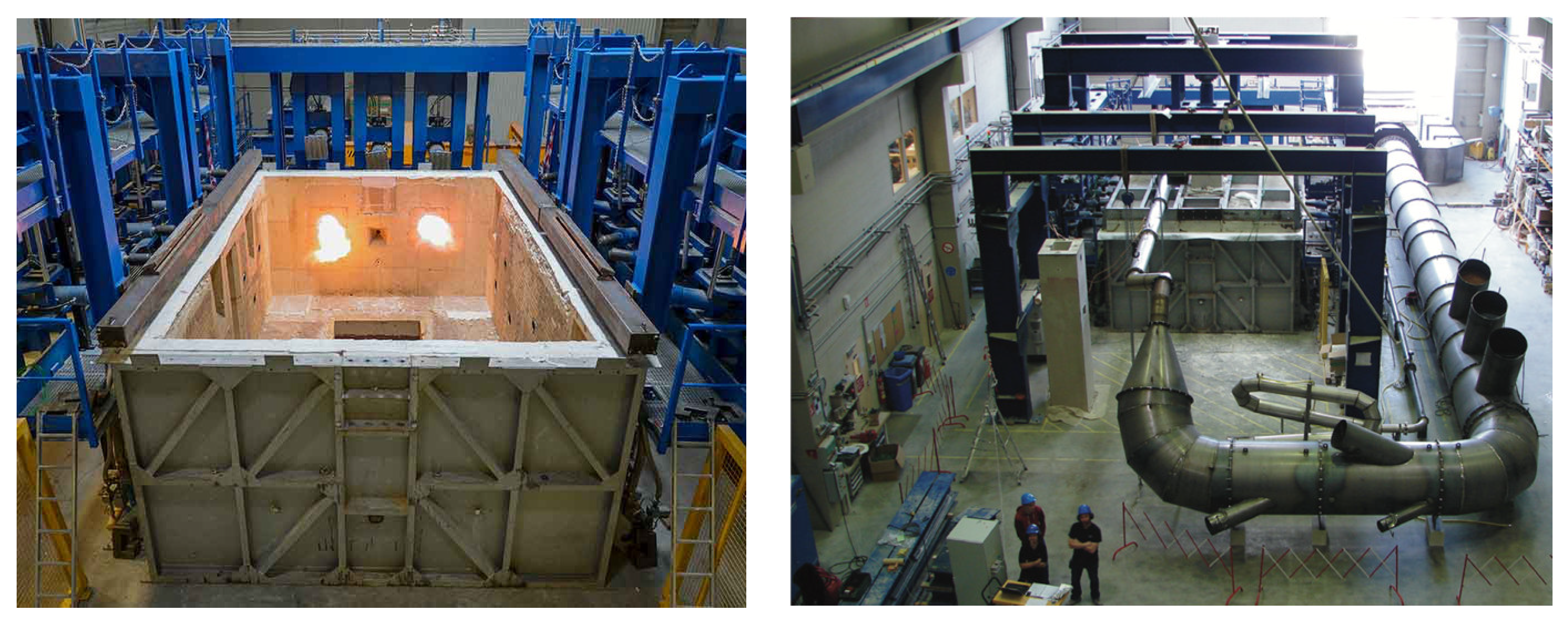
The tests conducted on the load-bearing walls were carried out in accordance with the protocols defined in EN 1363-1 [32] and EN 1365-1 [33]. Only the face containing the insulation layer was exposed to thermal action (Figure 10).
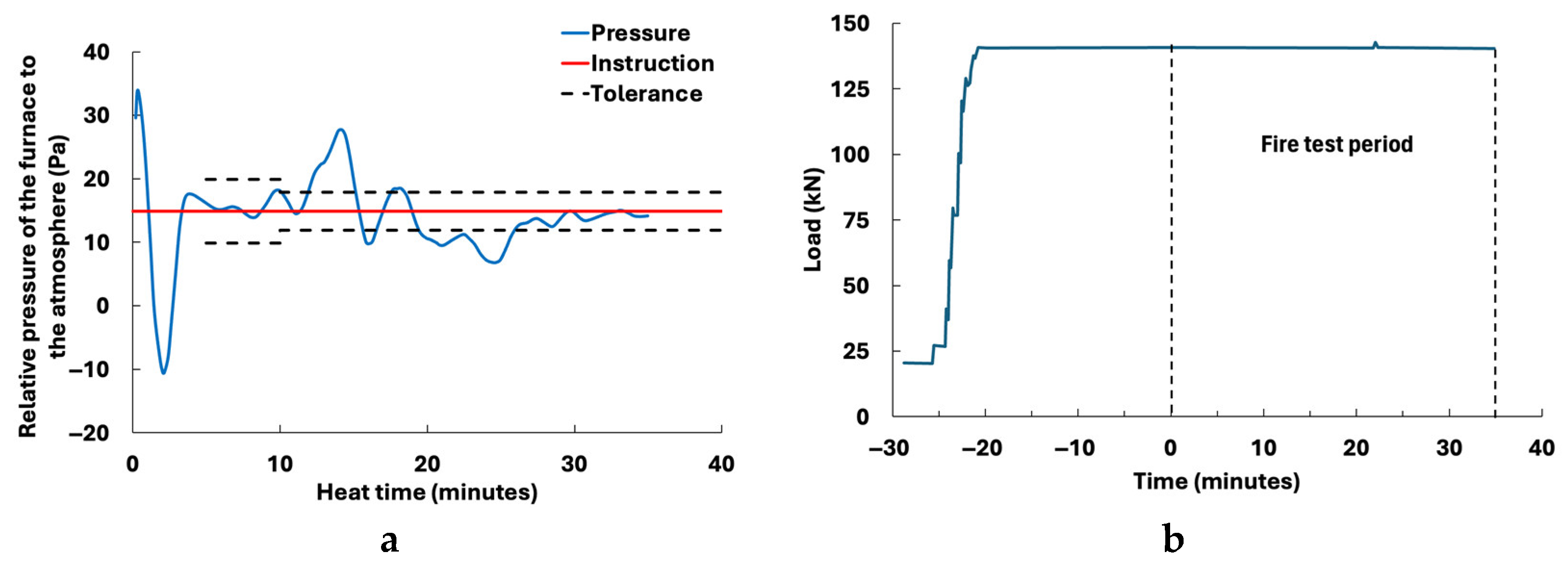
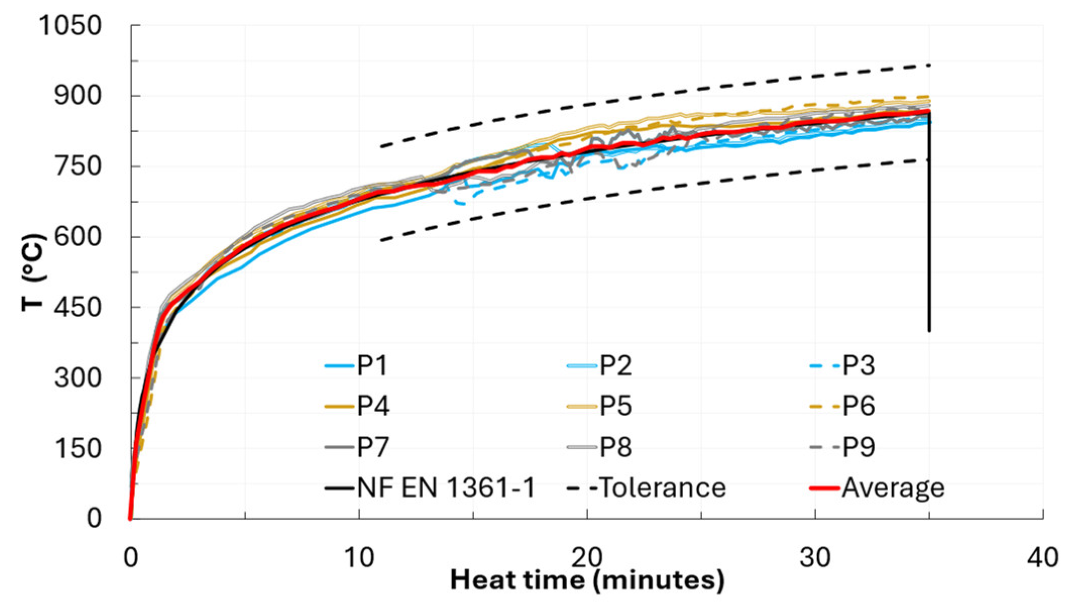
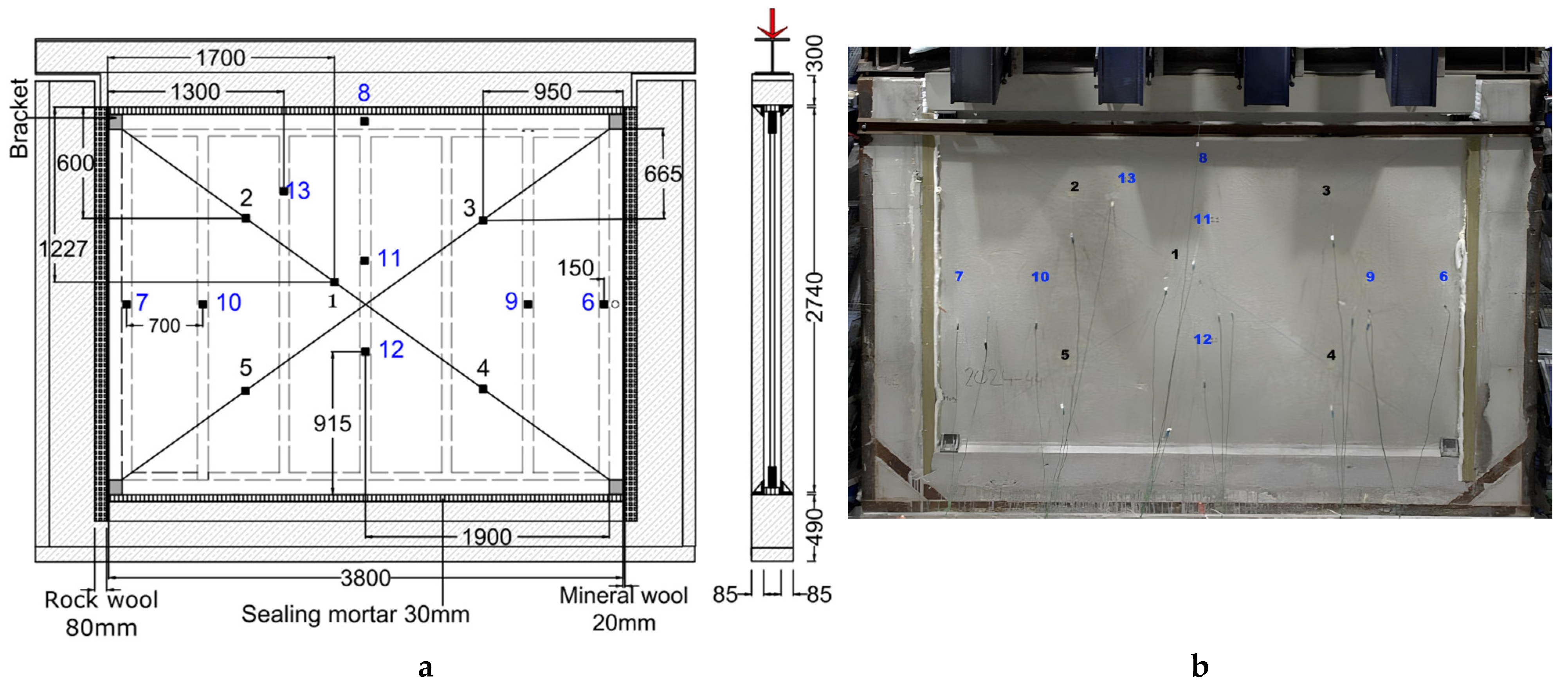
The furnace temperature was measured using 9 plate thermocouples, P1 to P9 (Figure 11a) positioned 10 ± 5 cm from the exposed surface of the wall, ensuring a minimum of one plate thermocouple per 1.2 m2. On the unexposed face (Figure 12), K-type disc thermocouples were used to monitor the temperature increase. Five of these thermocouples measured the temperature increase (1 to 5) across the current part of the wall, while the other eight measured the temperature increases at the stiffeners. The wall was installed within a RC frame and rested directly on a 3 cm-thick bed of cast-in-place mortar. A total vertical load of 148 kN, i.e., 38.9 kN/m, is applied to the top of the wall via a load distribution beam and four hydraulic jacks (see Figure 13b). The load applied to the wall before the fire test, and kept constant throughout, corresponds to the permanent load per linear meter of wall due to the weight of a floor, plus the service loads applied to the top slab. This load of 38.9 kN/m represents 5.4% of the ultimate compressive load, determined from another representative wall, whose measured ultimate capacity is 723.4 kN/m.
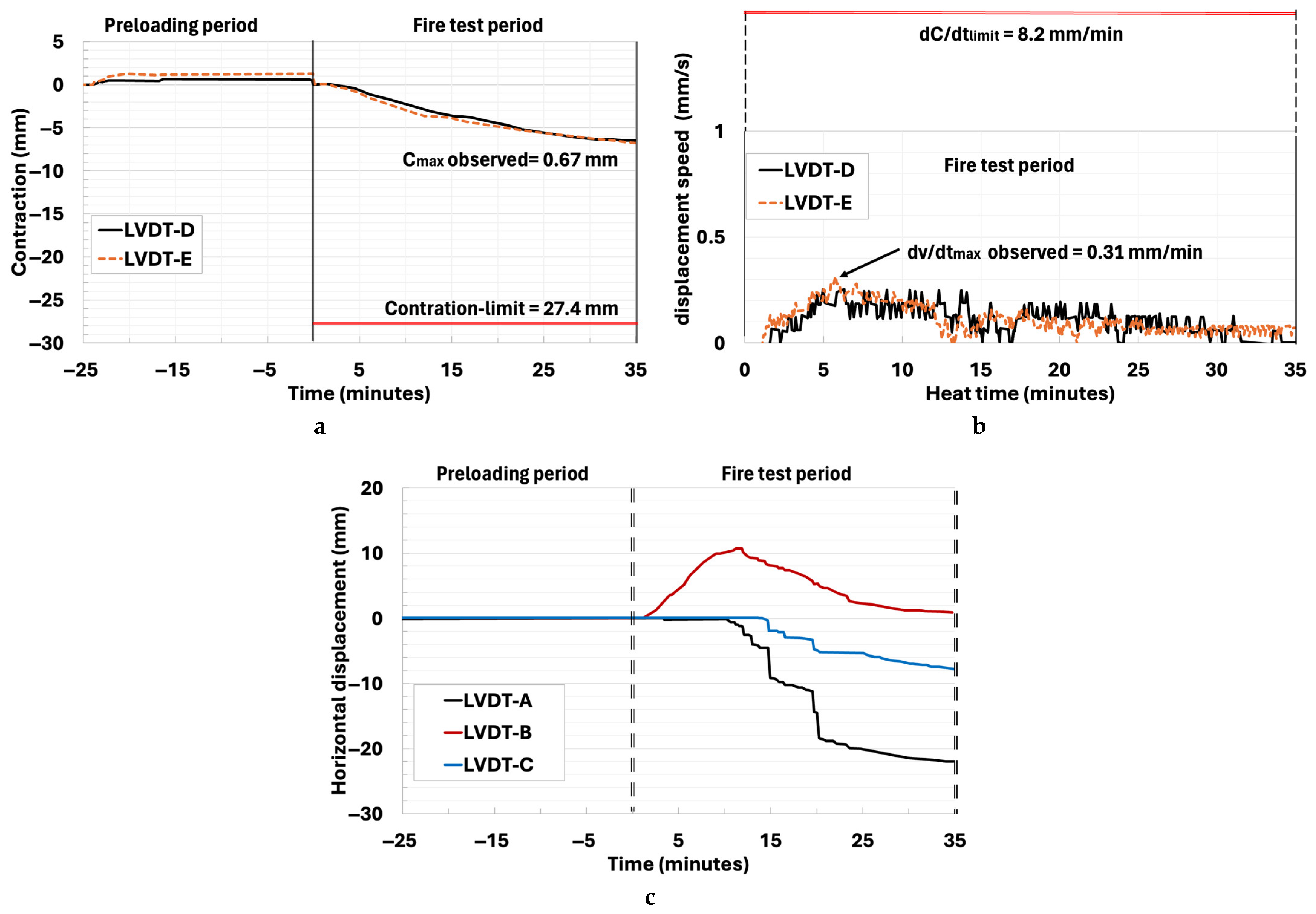
The two lateral sides of the wall are left free (unrestrained). Horizontal displacement of the wall was measured using three linear variable differential transformers (LVDTs), labelled A, B and C, positioned along the mid-height horizontal axis on the unexposed face of the wall. Two additional LVDTs, D and E (see Figure 11), located at the top of the wall, recorded vertical displacements. A negative vertical displacement indicates wall contraction (wall shortening).

5.1.2. Results and Analysis

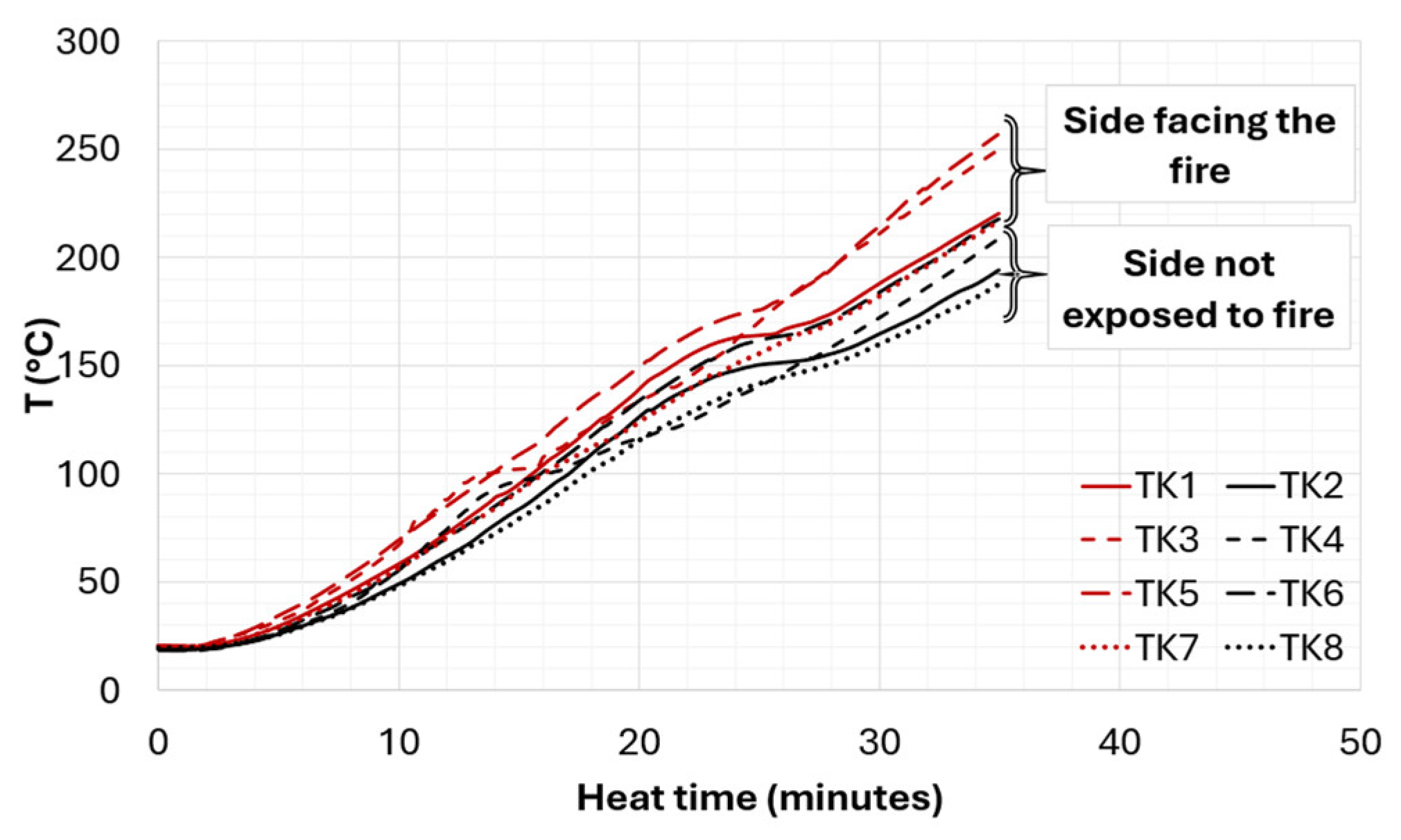
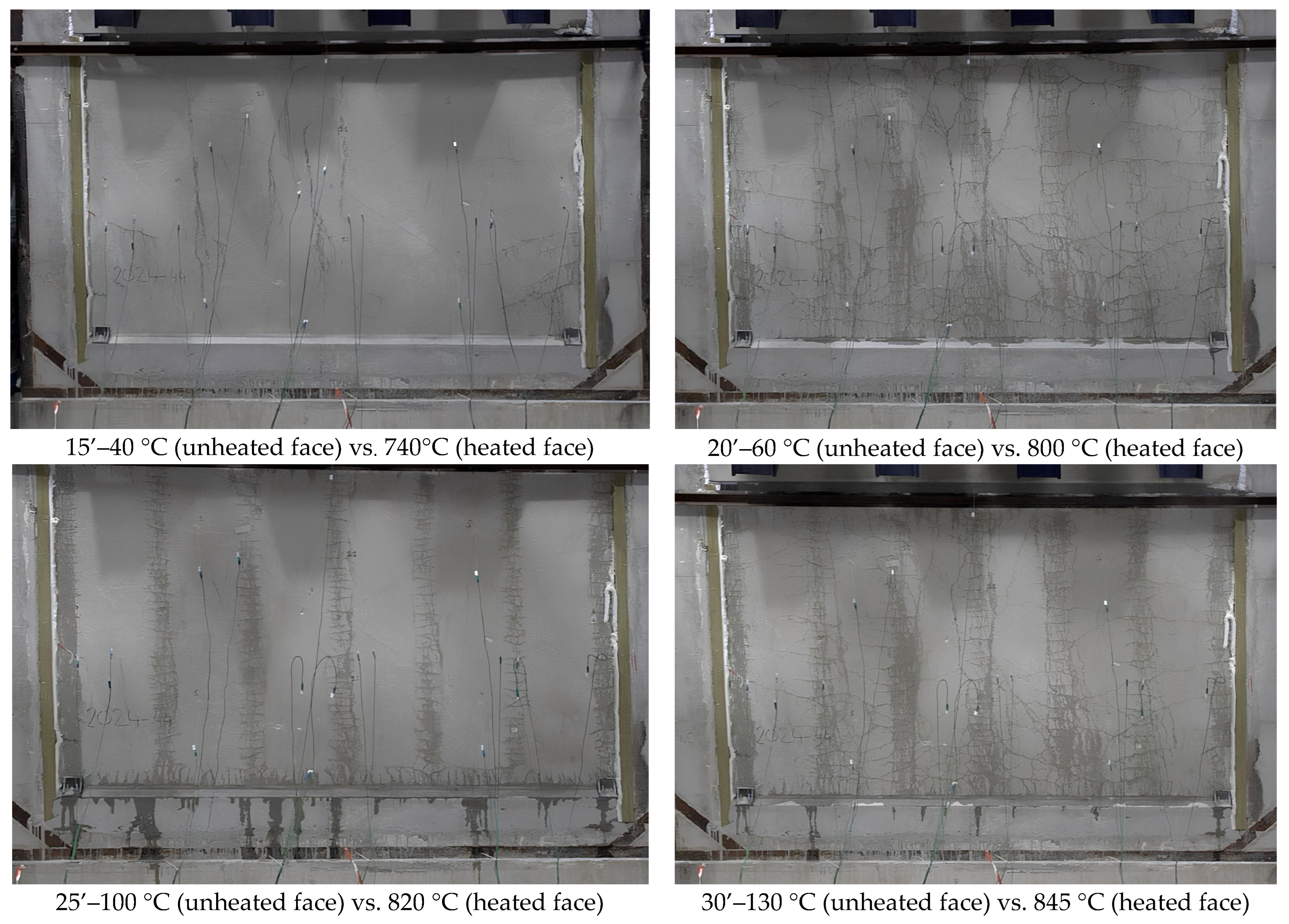
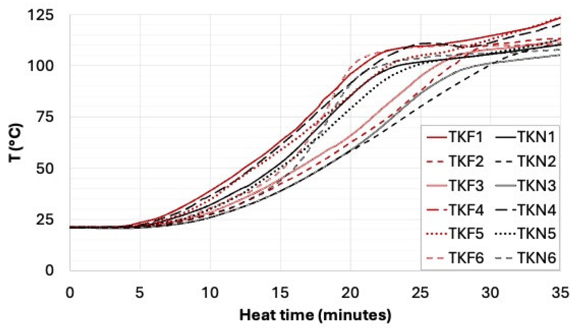
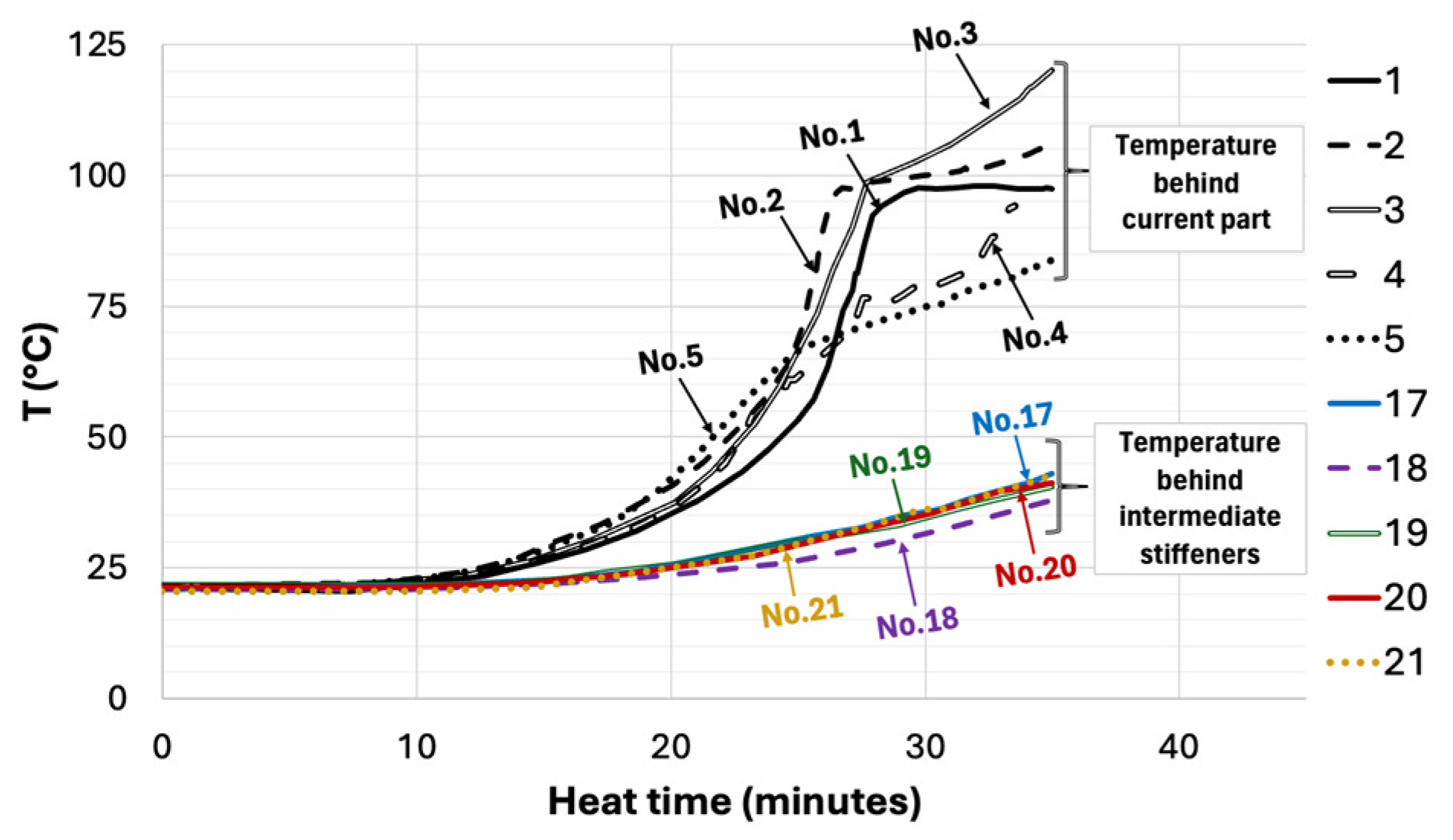
Figure 14 shows the temperature evolution during the 35 min fire loading test while Figure 15 presents the damage observed at 15 and 30 min. After the EPS insulation completely degraded, just a few seconds after the test began, heat started to penetrate the wall, as indicated by the rising temperatures recorded by thermocouples Tk1 to Tk8 (see Figure 16). This decomposition released gases, which were visible through the endoscopic camera, but did not cause significant internal overpressure or secondary spalling. Visual inspection after testing did not reveal any EPS residue due to concrete spalling. Figure 17 displays the temperature development on the unexposed face of the wall. The first instance of superficial spalling was observed on the fire-exposed surface after 9 min, within the constant thickness area near the wall’s free left edge (see Figure 18).
Within a few minutes, this spalling extended across the entire current zone of the wall. From the 12th minute (at approximately 705 °C), the temperature curves recorded by the pyrometers became irregular due to severe spalling, with fragments being ejected. This violent spalling was caused by a combination of mechanisms: vapor pressure build-up from the internal moisture of the concrete, thermal stresses due to significant temperature gradients, and mechanical stress caused by the vertical load applied to the top of the wall. As water vapor migrated towards the cooler areas (the unexposed face), pores became progressively saturated, forming “moisture plugs” that blocked vapor from escaping. This created a pressure gradient. When the internal pressure exceeded the tensile strength of the concrete, a sudden rupture of the surface layer occurred, expelling fragments 2 to 3 cm thick. In the case of non-fibered concrete, such spalling typically occurs at temperatures between 250 °C and 400 °C [34,35,36,37]. In the present test, however, the presence of PPF significantly increased the spalling threshold, with spalling only appearing around 700 °C. While SF do not improve the fire resistance directly, they do enhance the toughness of the concrete, helping to dissipate some of the energy released during spalling. The test was stopped after 35 min, when the average temperature on the exposed face had reached 870 °C, while the center of the unexposed face remained at around 240 °C (see Figure 17). However, no significant degradation was observed on this unheated face. Ten minutes after the beginning of the test, when the fire-exposed face had reached 680 °C, a horizontal microcrack appeared at the initial spalling zone, near the free edge. A vertical crack also developed at the center of the wall surface around the 12th minute (705 °C), causing the detachment of thermocouple No. 12. Several measurement devices positioned over the stiffeners (Tk Nos. 6, 9, 10, and 11) also detached during the test.
Figure 13. Fire test: (a) Furnace pressure; (b) applied load at the top of the load-bearing wall.
Fire 08 00458 g013
Figure 14. Temperature curves for the load-bearing wall: fire side.
Fire 08 00458 g014
Figure 15. Progression of wall damage with increasing heating temperature.
Fire 08 00458 g015
Figure 16. Temperature curves inside the stiffeners of the load-bearing wall.
Fire 08 00458 g016
Figure 17. Temperature curves on the unheated face of the load-bearing wall [32].
Fire 08 00458 g017
Figure 18. PP-SFRC spalling on heated face of the wall with spalling depth measurement.
Fire 08 00458 g018
The analysis of the water vapor path illustrated in Figure 19 shows an increased contraction of water vapor flow at the stiffeners. The melting of the PPF formed a significant pore network, while microcracks developed in the current zone of the wall facilitate the outward transfer of water vapor.
EN 1363-1 [32] defines the fire resistance of load-bearing structures based on its deformation and deformation speed. For vertical structures, such as the wall tested here, two criteria must be respected: the contraction must not exceed 1/100 of the height of the wall ( C l i m i t ) and the speed of contraction must remain below 3/1000 of the wall height ( d C / d t l i m i t ). Measurements taken with LVDTs D and E confirmed compliance with both criteria (see Figure 20a,b). LVDT B recorded a horizontal movement at the wall’s center (indicating deflection towards the heat source) during the first 12 min, while LVDT A and C remained relatively unaffected (Figure 20c). This movement results from thermal expansion associated with a loss of rigidity and/or thermal creep due to the constant load applied. However, after the 12 min period, another movement of the wall was observed. The wall shifted outward, away from the heat source, with a slight rotation to the right. This movement is more indicative of severe spalling as previously described on the exposed face, resulting in significant material loss on the heated face. The movement being more pronounced to the right (LVDT A) indicates the potential area of severe spalling. This assumption was later verified by measuring the spalling depth at 18 points across the wall surface after cooling (see Figure 18).
After 35 min of exposure to fire, the maximum spalling depth was 35 mm in the current section of the wall. This corresponds to a loss of 78.5% of the wall’s initial thickness in certain critical areas. Despite this damage, the wall maintained its load-bearing capacity, undergoing controlled deformation, even while supporting a compressive load of around 15 tons at the top. The high content of SF ensured the wall’s residual strength. However, the extent of spalling observed can be explained by several factors:
First, the water content of the wall at the time of testing was 4% in the current section and 3.9% in the stiffeners section (see Table 5) indicating that the concrete was still relatively young and undergoing hydration. According to Eurocode 2 [2], spalling can be avoided if the concrete’s water content is below 3%, and EN 1363-1 [32] specifies a maximum limit of 5% on the time of testing. Although this criterion alone does not seem sufficient, pre-drying the concrete at 60–80 °C to remove free water can significantly reduce the risk of spalling [38,39]. Second, the compressive load applied to the top of the wall may accelerate the development of spalling. Indeed, during fire testing, mechanical stress can delay the formation of heat-induced microcracks (perpendicular to the load direction) by partially closing them [40,41,42]. This effect reduces the permeability of the concrete to water vapor. Then the internal energy accumulates as the temperature rises, leading to spalling, which can be quite severe.

5.2. Stiffened Slab

5.2.1. Test Description

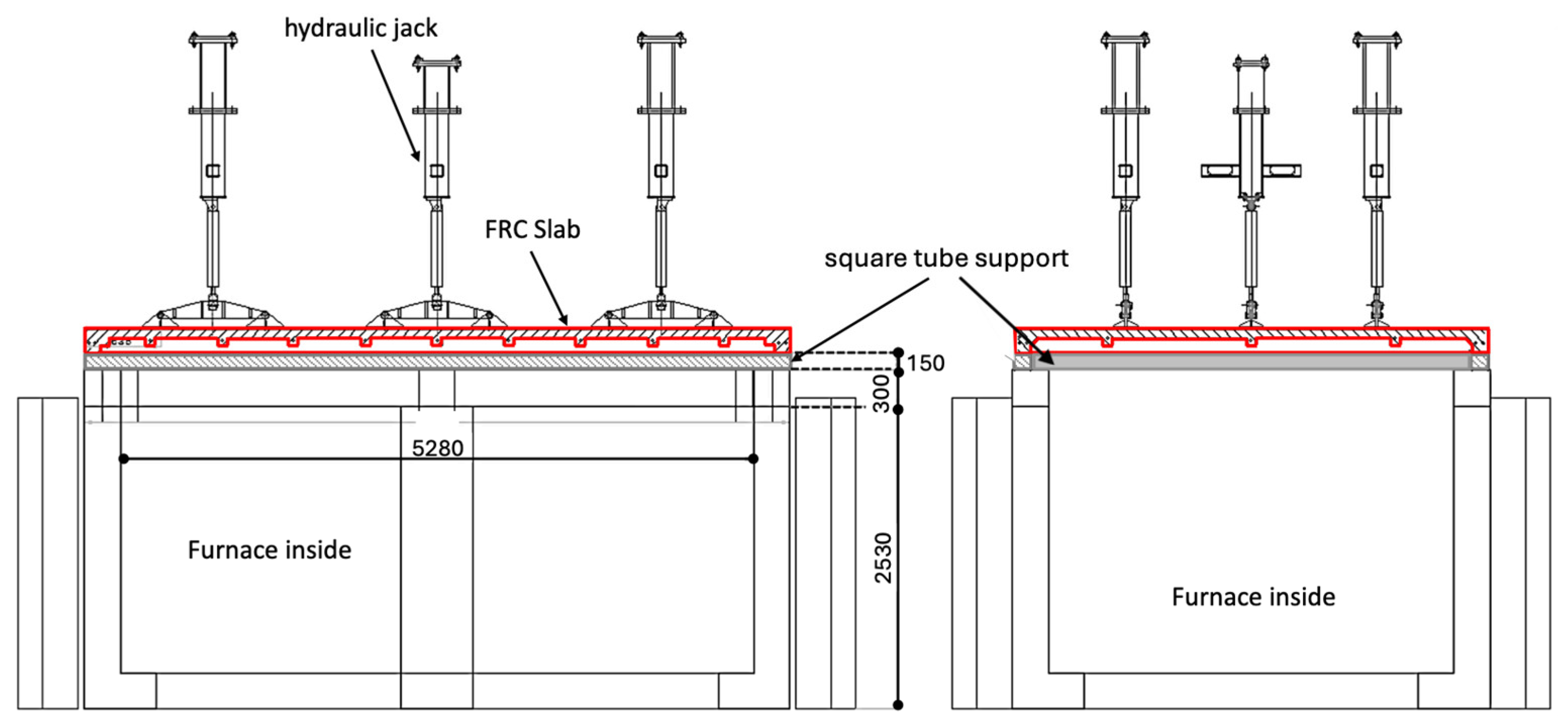
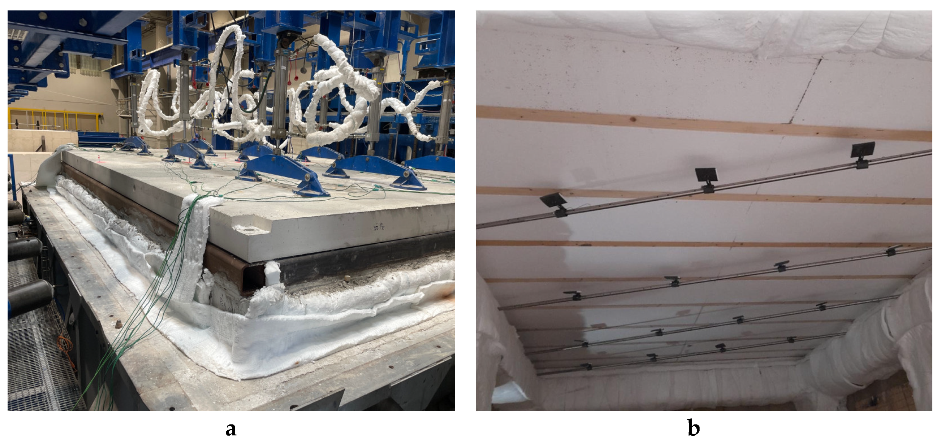
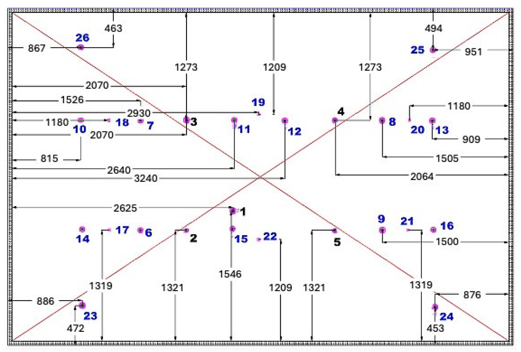
The fire resistance test on the stiffened slab was carried out in accordance with the requirements of EN 1363-1 [32] and EN 1365-2 [43]. The face being tested incorporated EPS insulation and was oriented towards the interior of the furnace, held in place by a CERIB support [44]. This support consisted of four beams resting on six columns. Four thermally protected steel tubes (cross-section: 150 × 150 mm2) were fixed at the corners of these beams, securely holding the slab in place (Figure 21). A mechanical load of 71.85 kN was applied to the casting face of the slab via nine hydraulic jacks, distributed across 18 points as shown in Figure 22. This load, corresponding to 3.5 kN/m2, was applied 21 min before the fire test began and was kept constant throughout. In addition, 26 K-type thermocouples (1 to 26) were installed on the unexposed face of the slab to monitor temperature rise (see Figure 23). Temperature evolution of the exposed face was monitored by sixteen pyrometers, placed 10 cm from this face, inside the furnace. Ten vertical displacement sensors (A to J) were installed on the unexposed face to measure vertical deformations (see Figure 24). Positive displacement indicates movement towards the furnace interior. The slab was also subjected to a pressure differential of 20 Pa between the inside and outside of the furnace. As the pressure sensor is located 73 cm below the face exposed to the fire, the furnace pressure was set to 14.6 Pa. Finally, two cameras with an endoscopic system were installed through one of the furnace walls, enabling visual monitoring of damage to the exposed face.

5.2.2. Degradation Mechanism

Following the test launch, the first signs of spalling appeared on the current section of the slab, after 9 min, between 680 and 705 °C, after the EPS insulation had completely degraded. This phenomenon spread progressively across the entire fire-exposed face over the next 20 min. Furthermore, the increase in temperature caused the degradation of the solid timber (KVH) used on the surface of the stiffeners, which induced further heat transfer to the concrete. By the 29th minute of the test, severe spalling had occurred where the phenomenon first appeared. The test was interrupted after 35 min of fire exposure, and at this point, the furnace temperature reached 840 °C (Figure 25).
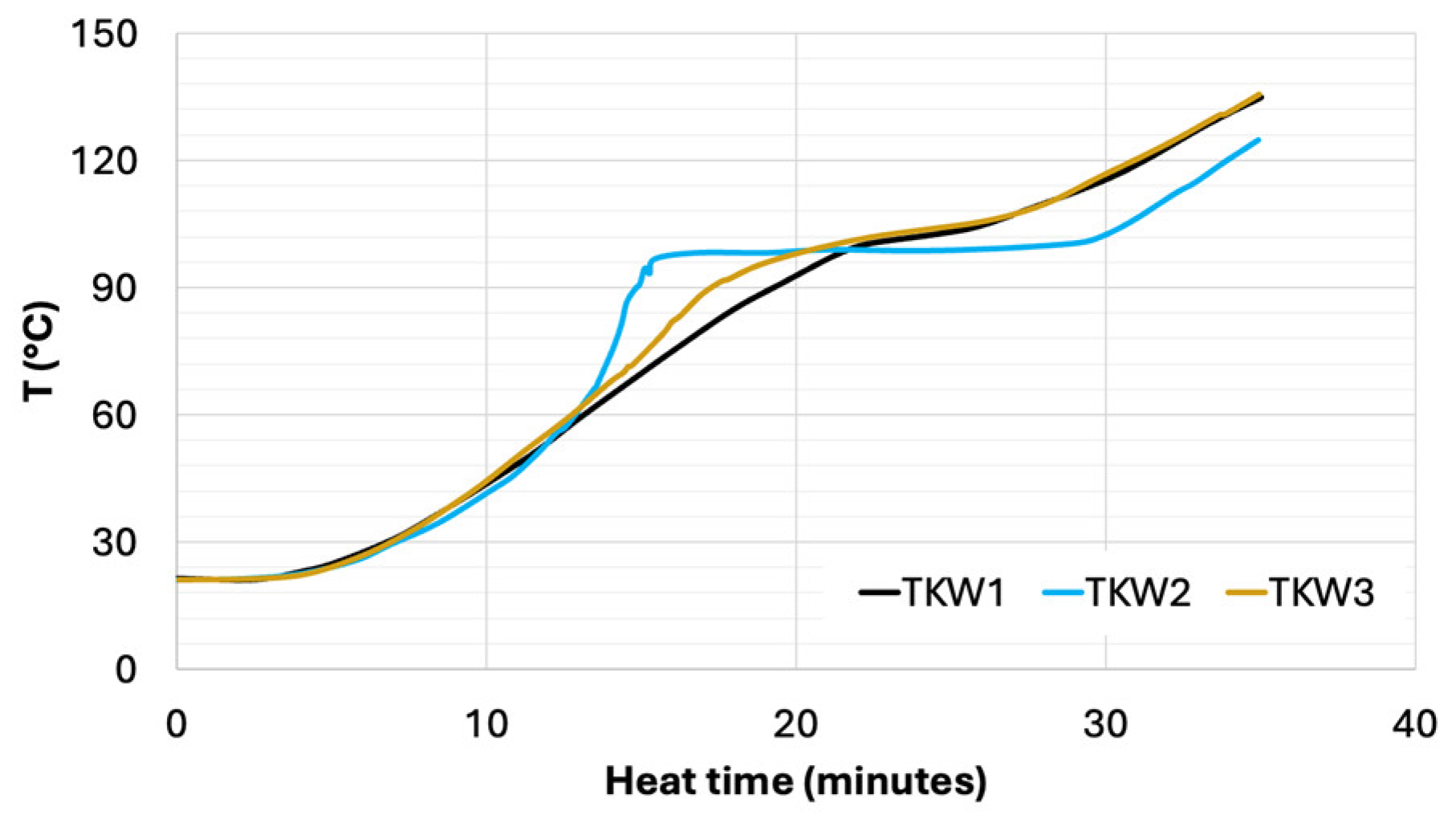
Measurements showed a maximum temperature of 138 °C at the interface between the concrete and the burnt wood zone (Figure 26), 120 °C within the concrete of the stiffeners (Figure 27). On the opposite face, not exposed to the fire, maximum temperature of 42 °C and 120 °C were recorded, respectively, just behind the stiffeners and current sections of the slab (Figure 28).
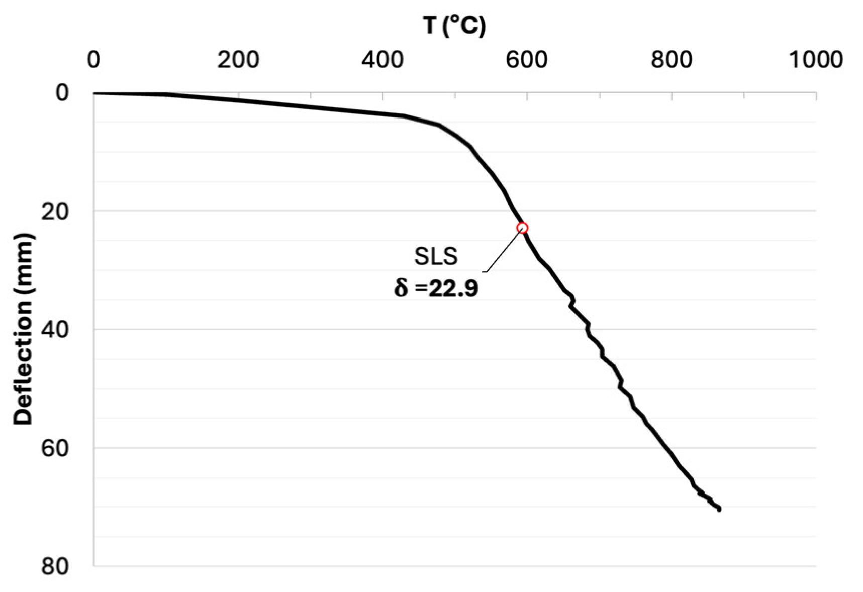
The maximum deflection observed at the center of the slab was 70 mm, as indicated by LVDT C (Figure 29). This deflection is relatively greater than what is generally reported for RC slabs in the literature, mainly due to the absence of conventional reinforcement. Nevertheless, the slab’s rotational capacity is higher because of its thin thickness and the high SF content. Under thermal loading (Figure 30), the deflection at the serviceability limit state (L/250) was reached after 6 min of testing at approximately 600 °C. However, based solely on the resistance criteria of EN 1363-1 [32], the slab satisfies the fire resistance requirements beyond this temperature (up to 840 °C).
EN 1363-1 [32] provides a test protocol for evaluating the fire resistance of a construction elements. While valuable, these tests do not constitute a structural design method as defined by the Eurocodes, which include Service and Ultimate Limit State checks, complex or combined actions, and partial safety factors. Structural verification according to the EN 1990 [45] and EN 1991 [46] was performed during the design phase. In this study, EN 1363-1 [32] tests have been conducted solely to assess the wall’s behavior under fire exposure and to verify its performance under these conditions. EN 1363-1 [32] offers empirical validation of fire performance and is therefore complementary to regulatory calculation methods, which must be used alongside it to guarantee overall structural safety during a fire (Equations (1) and (2)).
( D l i m i t s l a b ) = L 2 400 t = 358   mm
( d D / d t l i m i t s l a b ) = L 2 9000 t   m m / m i n = 16   mm / m i n
« L » represents the small span of the slab and « t » its thickness. In this case, slab deflection (the maximum vertical displacement) of 70 mm and its speed of 6 mm/min were less than the limits set by Equations (1) and (2).

5.2.3. Post-Fire Damage and Residual Strength of Slabs

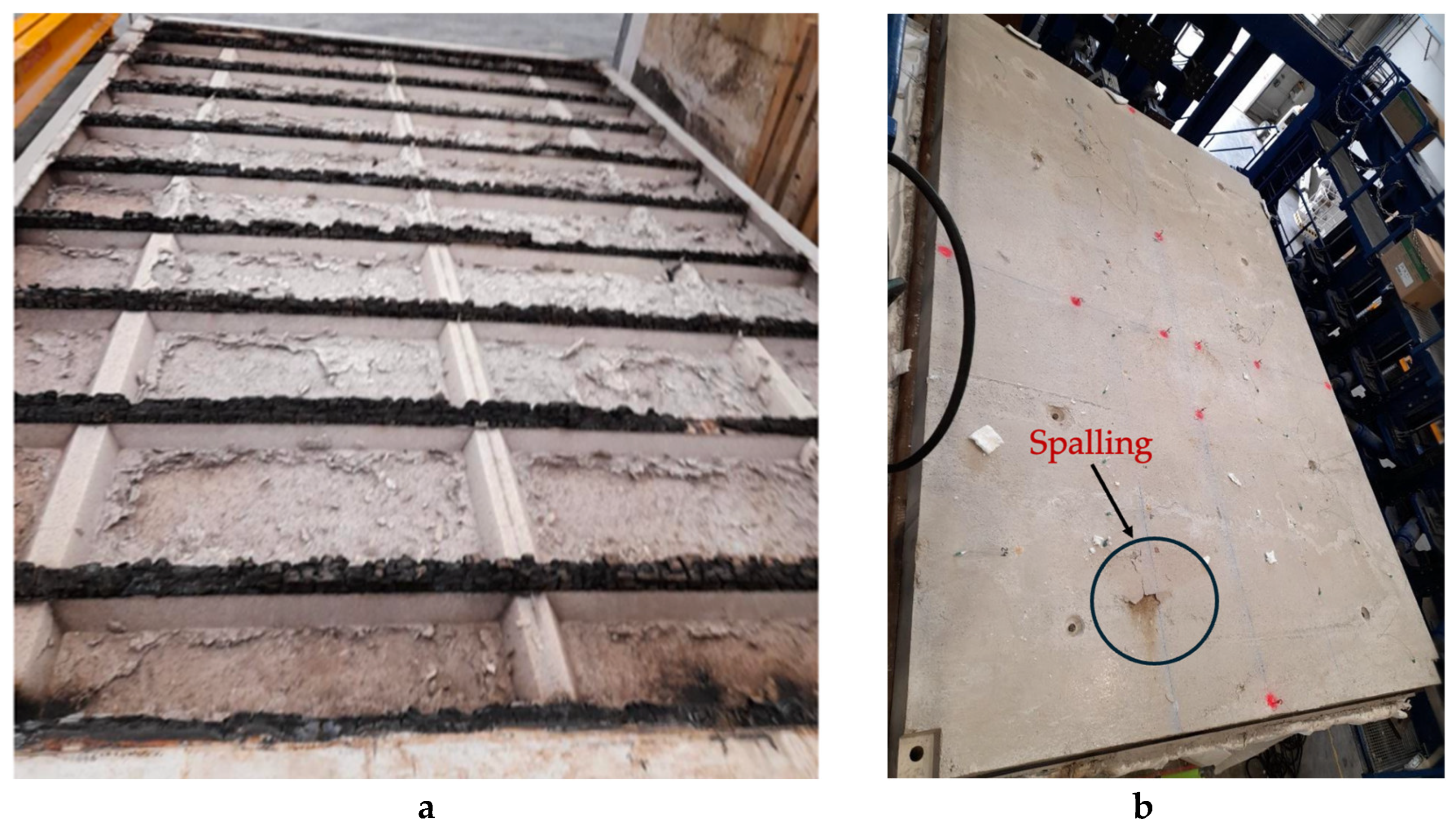
The post-fire inspection revealed that spalling induced by elevated temperatures was particularly severe in the current part of the slab. No spalling was observed in the stiffened zones. The absence of spalling in the stiffened areas is likely due to a combination of effects. The increased local thickness (and thus higher thermal inertia) delayed the temperature rise near the reinforcement ribs. In addition, the stiffeners were protected by solid KVH timber, which has a higher fire resistance compared to the EPS insulation used in the main slab layer. This timber protection helps limit heat penetration and local expansion of the concrete, reducing tensile stresses and restraining the onset of spalling. The placement of KVH timber was done in preparation for upcoming finishing works. Figure 31 illustrates the spalling observed on the various surfaces of the slab. After cooling, the average spalling depths on the fire-exposed face was 32 mm, representing a loss of 50% of the thickness in the current part.
The four corners of the slab were unaffected by spalling (see Figure 32). Two slab specimens, S1 and S2 (see Table 6) were then cut from the fire-tested element for further assessment of residual strength. The average density of these slab pieces was 2168 kg/m3, a decrease of approximately 10%, attributed to water loss during fire exposure and the formation of an extensive pore network resulting from concrete cracking. The water content of the fresh concrete was 9.1% at casting moment, dropping to 4.5% just before the fire test due to drying. This value still exceeds the maximum limit of 3% specified by Eurocode 2 [2]. Consequently, the fire exposure led to concrete spalling (Figure 31a) and reduced the residual free water content to almost zero. Using a Grindosonic device, the residual dynamic elastic modulus was measured at 9.4 GPa, which around 73.3% lower than the initial value of 35.2 GPa (noted earlier in Section 2). This substantial decrease is primarily due to the progressive dehydration of cement hydration products, the formation of thermally induced microcracks, and the deterioration of the cement paste/aggregate interface. From 300 °C, water loss begins to compromise the material’s internal cohesion. Beyond 600 °C, the slag-based cement paste structure (C-A-S-H) begins to decompose, and the aggregates undergo physicochemical transformations and increasing cracking. These combined effects significantly reduce the concrete’s ability to carry elastic stresses, leading to a pronounced reduction in its modulus of elasticity.
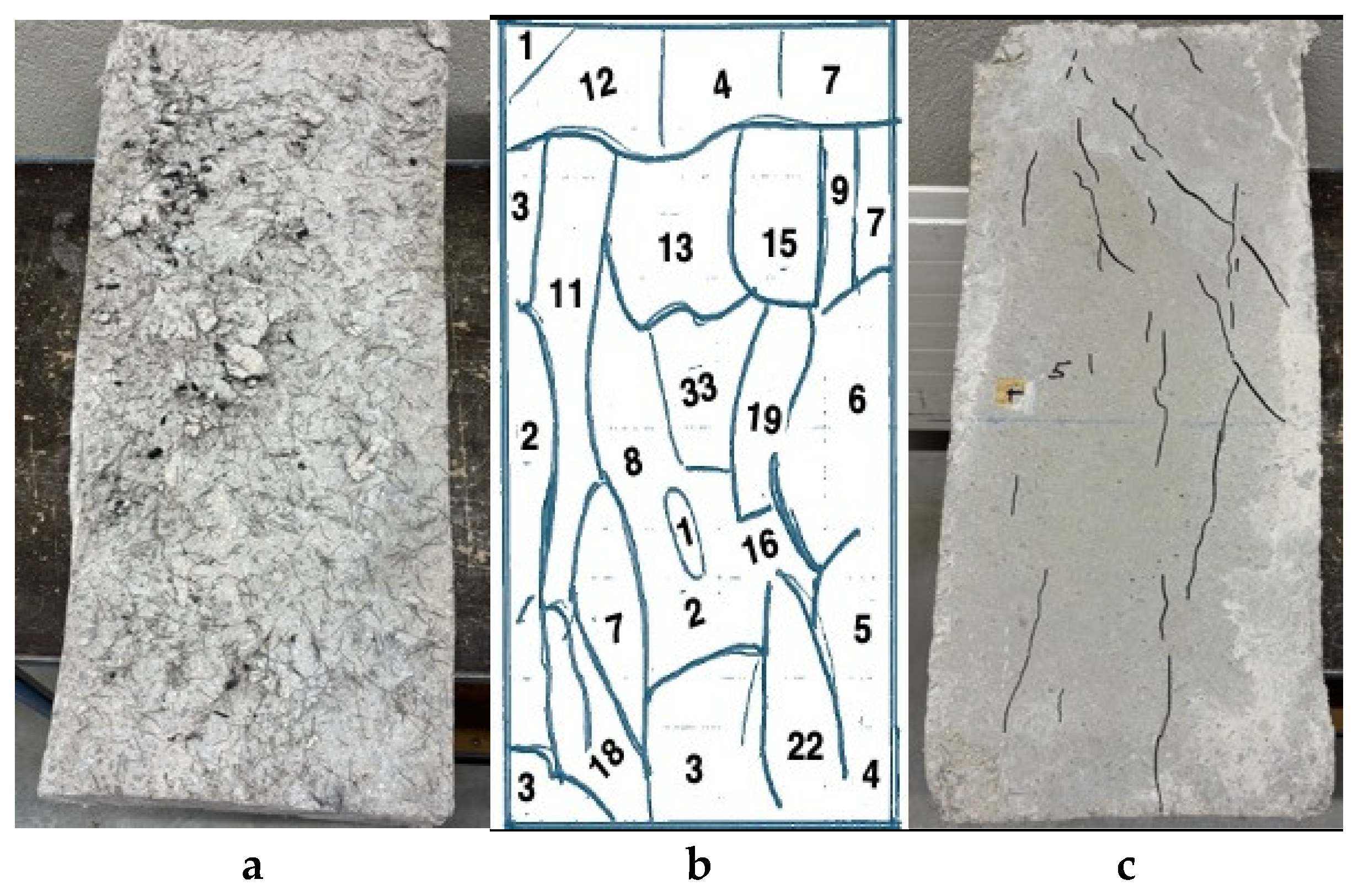
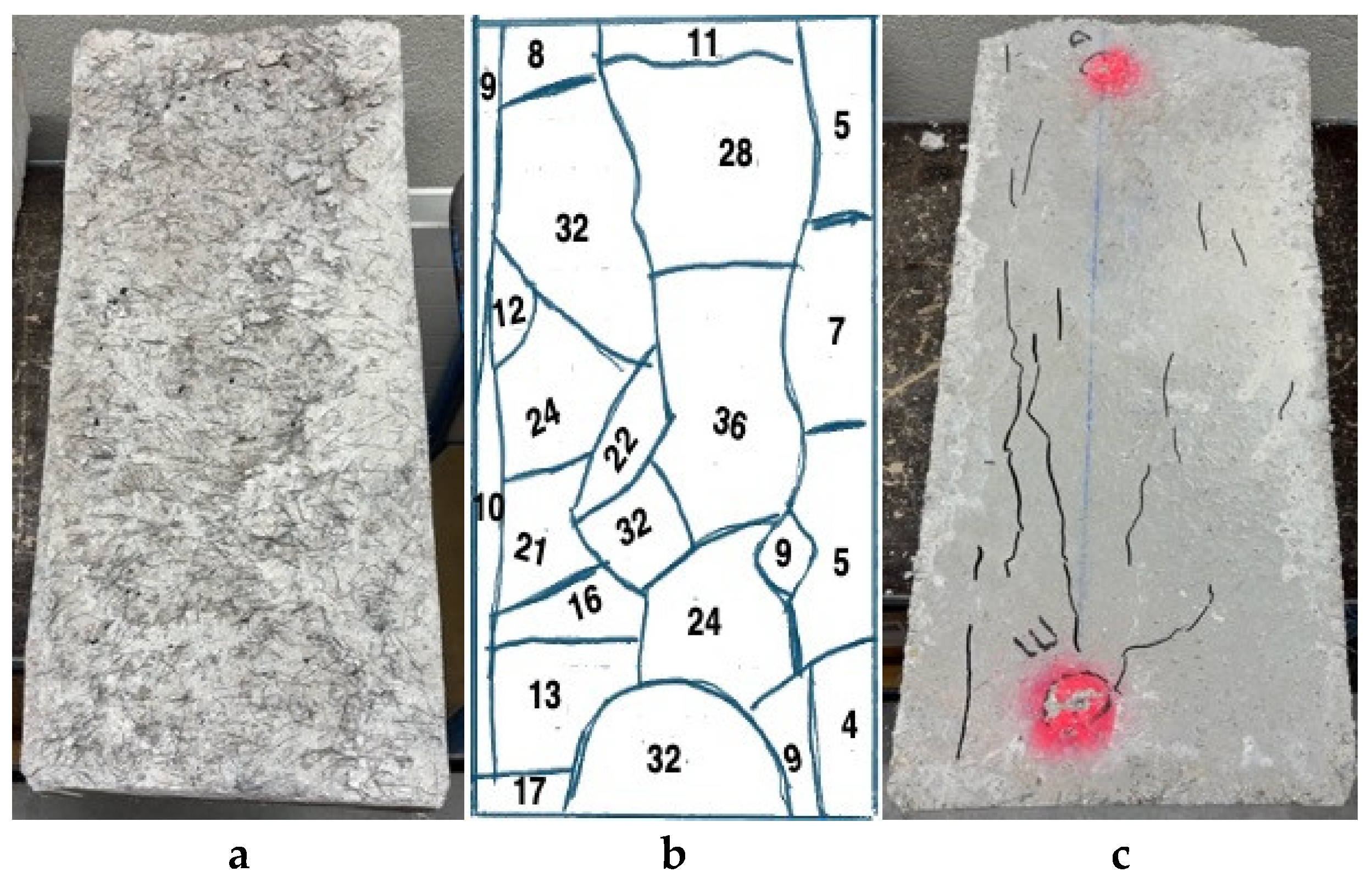
Figure 33a,b and Figure 34a,b illustrate the spalling observed on the cut slab specimens. The most severely damaged areas are located at the center of the slabs, while the least affected zones are near the ribs. There is significant material loss, with maximum spalling depths reaching 33 mm in slab S1 and 36 mm in slab S2. The black marks on the exposed surfaces are the result of KVH timber decomposition under fire. The SFs appear blackened and are sometimes covered with a thin layer of rust; however, their hooked ends show no visible deformation. The aggregates retain their original appearance, though some display radial cracking or signs of surface degradation. On the non-exposed faces, cracks are mostly oriented along the main span direction. However, their origin remains uncertain. They do not appear to be directly linked to thermal exposure and may have developed during the cooling phase.
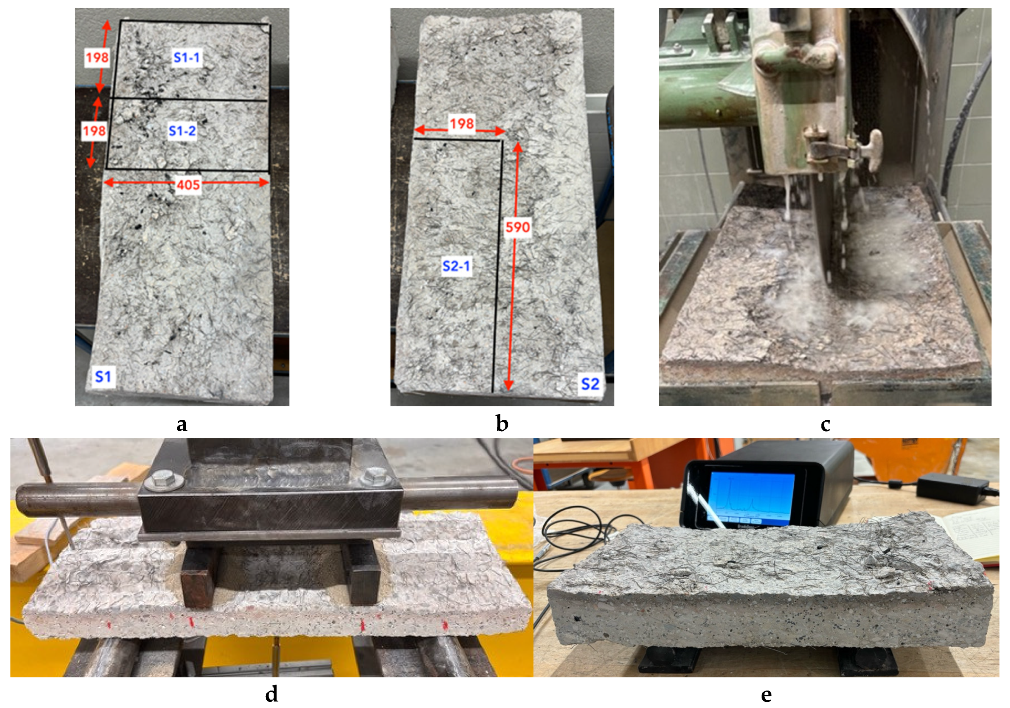
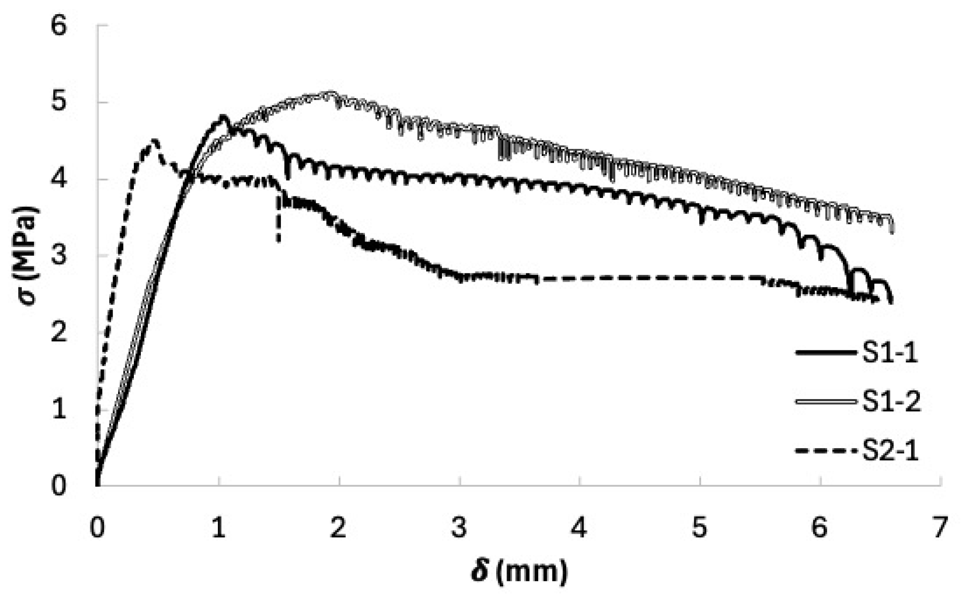
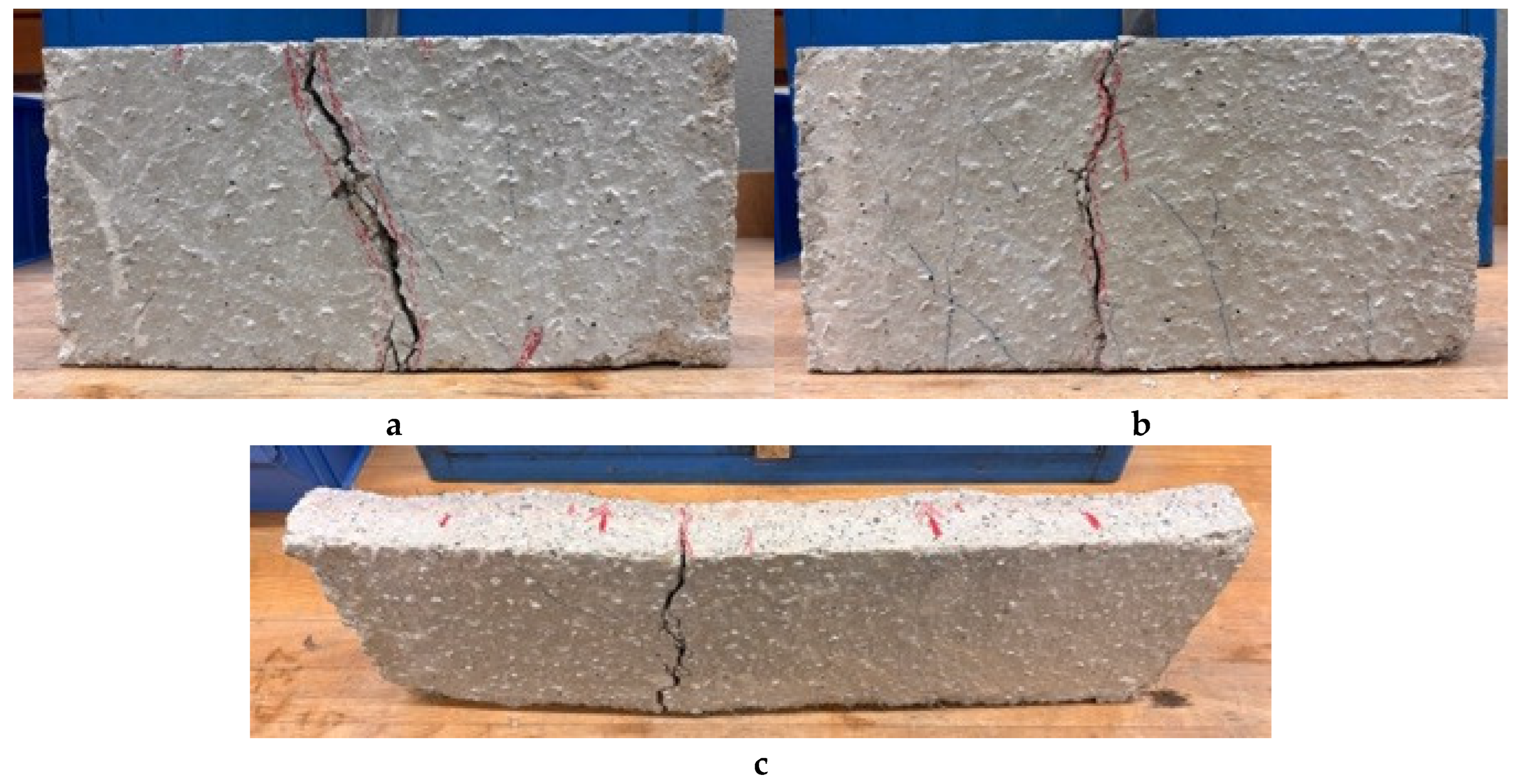
To determine the residual mechanical strength of the PP-SFRC, 4-point bending tests were carried out on specimens extracted from the fire-tested slab (Table 7). Figure 35a–c shows the preparation of the three tested specimens. The load was applied on the spalled face. A layer of sand was used to fill surface irregularities and ensure uniform loading. The stress-deflection (σ-δ) curves show an average strength of 4.97 MPa for the specimens from slab S1 and 4.5 MPa for the specimens from slab S2 (see Figure 36). The post-peak response exhibited ductility with negative strain hardening, indicating a gradual failure process that contributes positively to fire safety. The SF within the cracked sections helped to restrain crack opening and propagation. All specimens failed in bending, with the main crack forming at the location of the maximum bending moment (see Figure 37). The strength results demonstrate that the mechanical properties were not significantly degraded, confirming that the PP-SFRC exhibited good post-fire performance.
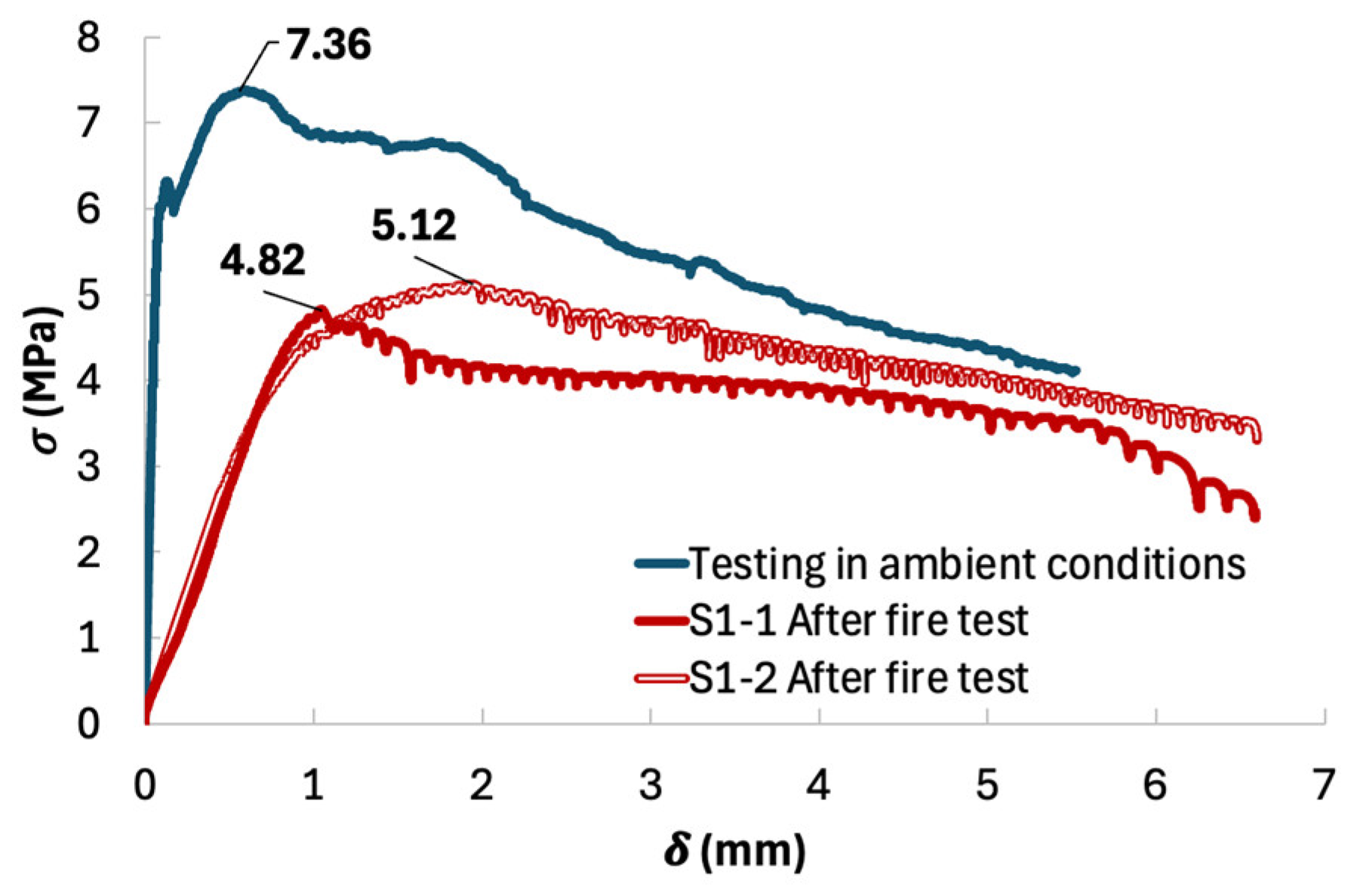
Figure 38 compares the flexural strength of slabs S1-1 and S1-2 with that of a slab of the same dimensions and tested at ambient temperature. A clear difference in initial stiffness is observed. This reduction in modulus reflects damage to the material caused by elevated temperatures, leading to microcracking and increased porosity. These observations corroborate the earlier results obtained from the elastic modulus measured using the Grindosonic. A strength loss relative to the reference specimen is also noticeable, amounting to 43.8% and 52.7% for the cut slab S1-2 and S1-1, respectively. Despite this reduction in strength, the material’s ductility remains intact, and no brittle failure was observed. SFs did not expand, as the test was halted at 840 °C, enabling them to maintain their anchorage and continue contributing to post-crack behavior.

6. Conclusions

This work provides a novel experimental contribution to the fire design of thin fiber-reinforced panels for modular construction. Fire tests were conducted on structural elements of a new 3D modular construction concept. These planar, stiffened PP-SFRC structures are thin, with walls measuring only 7 cm for the slabs and 5 cm for the panels. Performed according to the ISO 834-1 curve [31], the fire tests demonstrated a resistance of at least 30 min, thus meeting the requirements specified for an individual house (two-story house). Concrete spalling was observed, likely due to the moisture content exceeding 3% at the time of testing. However, the presence of only 0.3 kg/m3 of PPF had a beneficial effect, as this spalling was better controlled over time due to the vapor escape channels created by the melting of these plastic fibers. Both integrity and load-bearing capacity were maintained beyond the required 30 min duration.
Post-mortem analysis of the slab revealed good residual performance of PP-SFRC structures. The final elastic modulus of 9.4 GPa represents a 73.3% reduction from the initial value of 35.2 GPa. The average concrete spalling depths were 25 mm and 32 mm for the wall and the slab, respectively. Flexural tests carried out on specimens cut from the slab after the fire showed good residual strength, with strength losses ranging from 43.8% to 52.7%, while ductility was preserved.
The findings of this study open several avenues for further research aimed at deepening the understanding and optimizing the fire performance of thin PP-SFRC structural elements. First, a systematic investigation into the influence of polypropylene and steel fiber content is required to identify the most effective configurations for mitigating spalling while maintaining satisfactory residual mechanical properties. The incorporation of hybrid fibers or specific additives could also be explored for this purpose.
Moreover, the effect of the initial moisture content on fire behavior and spalling severity requires thorough analysis. Controlled experimental campaigns, complemented by in situ measurements, would help define critical thresholds and develop preventive conditioning or protective measures.
Finally, a system-level approach that considers the complete modular assembly, including joints, connections, and thermal transfer between elements, is essential to assess the overall fire resistance of modular buildings and identify improved constructive solutions.

Author Contributions

Conceptualization, S.A.S.L.S., T.-T.B. and A.L.; Methodology, S.A.S.L.S., T.-T.B. and A.L.; Validation, D.D. and A.L.; Investigation, D.D. and A.L.; Writing—original draft, S.A.S.L.S., T.-T.B. and A.L.; Writing—review and editing, S.A.S.L.S., A.B., T.-T.B. and A.L.; Supervision, A.L. All authors have read and agreed to the published version of the manuscript.

Funding

This research received no external funding.

Institutional Review Board Statement

Not applicable.

Informed Consent Statement

Not applicable.

Data Availability Statement

The original contributions presented in the study are included in the article, further inquiries can be directed to the corresponding author/s.

Acknowledgments

This article was prepared as part of the project Construction of a 2-story modular house in 60 days, project which was conducted by Cubik and Francioli. The project has since been completed, and the dwelling was installed in Chaleins, located in the Auvergne-Rhône-Alpes region of France. The authors gratefully acknowledge the contributions of Cubik Home and Francioli, as well as the CERIB (French Concrete Industry Technical Centre) for their expertise and valuable support in the experimental investigations at high temperatures.

Conflicts of Interest

Author D. Damichey was employed by the company CUBIK-HOME. The remaining authors declare that the research was conducted in the absence of any commercial or financial relationships that could be construed as a potential conflict of interest.

References

  1. Chen, L.; Huang, Z.; Pan, W.; Su, R.K.L.; Zhong, Y.; Zhang, Y. Low carbon concrete for prefabricated modular construction in circular economy: An integrated approach towards sustainability, durability, cost, and mechanical performances. J. Build. Eng. 2024, 90, 109368. [Google Scholar] [CrossRef]
  2. NF EN 1992-1-2; Eurocode 2: Design of Concrete Structures—Part 1–2: General Rules—Structural Fire Design. Association Francaise de Normalisation (AFNOR): La Plaine Saint-Denis, France, 2005.
  3. Fire Design of Concrete Structures; fib Bulletin, No. 38; The International Federation for Structural Concrete: Lausanne, Switzerland, 2007. [CrossRef]
  4. NF P92-701: FB Calculation Method—Calculation Method Used for Forecasting the Fire Resistance of Concrete Structures, AFNOR, 45 p 1993. Available online: https://www.boutique.afnor.org/en-gb/standard/p92701/fb-calculation-method-calculation-method-used-for-forecasting-the-fire-resi/fa036571/275 (accessed on 24 November 2025).
  5. Lyu, X.; Wang, W.; Xu, Q.; Wu, F.; Yi, S.; Yu, Y. Post-fire behaviors of stiffened concrete-filled thin-walled square steel tubular slender columns: Experimental and numerical investigations. Structures 2025, 78, 109348. [Google Scholar] [CrossRef]
  6. Heo, Y.-S.; Sanjayan, J.G.; Han, C.-G.; Han, M.-C. Limited effect of diameter of fibres on spalling protection of concrete in fire. Mater. Struct. 2012, 45, 325–335. [Google Scholar] [CrossRef]
  7. Liu, X.; Ye, G.; De Schutter, G.; Yuan, Y.; Taerwe, L. On the mechanism of polypropylene fibres in preventing fire spalling in self-compacting and high-performance cement paste. Cem. Concr. Res. 2008, 38, 487–499. [Google Scholar] [CrossRef]
  8. Bangi, M.R.; Horiguchi, T. Effect of fibre type and geometry on maximum pore pressures in fibre-reinforced high strength concrete at elevated temperatures. Cem. Concr. Res. 2012, 42, 459–466. [Google Scholar] [CrossRef]
  9. Maluk, C.; Bisby, L.; Terrasi, G.P. Effects of polypropylene fibre type and dose on the propensity for heat-induced concrete spalling. Eng. Struct. 2017, 141, 584–595. [Google Scholar] [CrossRef]
  10. Hiremath, P.N.; Yaragal, S.C. Performance evaluation of reactive powder concrete with polypropylene fibers at elevated temperatures. Constr. Build. Mater. 2018, 169, 499–512. [Google Scholar] [CrossRef]
  11. Li, S.; Gondokusumo, G.S.; Venkateshwaran, A.; Liew, J.Y.R. Structural behaviour of steel fibre-reinforced concrete floor system for modular construction. Eng. Struct. 2023, 291, 116437. [Google Scholar] [CrossRef]
  12. Yermak, N.; Pliya, P.; Beaucour, A.-L.; Simon, A.; Noumowé, A. Influence of steel and/or polypropylene fibres on the behaviour of concrete at high temperature: Spalling, transfer and mechanical properties. Constr. Build. Mater. 2017, 132, 240–250. [Google Scholar] [CrossRef]
  13. Zeiml, M.; Leithner, D.; Lackner, R.; Mang, H.A. How do polypropylene fibers improve the spalling behavior of in-situ concrete? Cem. Concr. Res. 2006, 36, 929–942. [Google Scholar] [CrossRef]
  14. Lee, W.M.; Fragomeni, S.; Monckton, H.; Guerrieri, M. A review of test Methods, issues and challenges of Large-Scale fire testing of concrete tunnel linings. Constr. Build. Mater. 2023, 392, 131901. [Google Scholar] [CrossRef]
  15. Serafini, R.; Dantas, S.R.A.; Agra, R.R.; de la Fuente, A.; Berto, A.F.; de Figueiredo, A.D. Design-oriented assessment of the residual post-fire bearing capacity of precast fiber reinforced concrete tunnel linings. Fire Saf. J. 2022, 127, 103503. [Google Scholar] [CrossRef]
  16. Tatnall, P.C. Shotcrete in Fires: Effects of Fibers on Explosive Spalling. Shotcrete 2002, 4, 10–12. [Google Scholar]
  17. Kalifa, P.; Chéné, G.; Gallé, C. High-temperature behaviour of HPC with polypropylene fibres: From spalling to microstructure. Cem. Concr. Res. 2001, 31, 1487–1499. [Google Scholar] [CrossRef]
  18. Serrano, R.; Cobo, A.; Prieto, M.I.; González, M.d.l.N. Analysis of fire resistance of concrete with polypropylene or steel fibers. Constr. Build. Mater. 2016, 122, 302–309. [Google Scholar] [CrossRef]
  19. McNamee, R.; Sjöström, J.; Boström, L. Reduction of fire spalling of concrete with small doses of polypropylene fibres. Fire Mater. 2021, 45, 943–951. [Google Scholar] [CrossRef]
  20. Khayat, K.H.; De Schutter, G. (Eds.) Mechanical Properties of Self-Compacting Concrete: State-of-the-Art Report of the RILEM Technical Committee 228-MPS on Mechanical Properties of Self-Compacting Concrete; RILEM State-of-the-Art Reports; Springer International Publishing: Cham, Switzerland, 2014; Volume 14. [Google Scholar] [CrossRef]
  21. Noumowé, A.; Carré, H.; Daoud, A.; Toutanji, H. High-Strength Self-Compacting Concrete Exposed to Fire Test. J. Mater. Civ. Eng. 2006, 18, 754–758. [Google Scholar] [CrossRef]
  22. Sawadogo, S.A.S.L.; Bui, T.T.; Bennani, A.; Al Galib, D.; Reynaud, P.; Limam, A. 3D Modular construction made of precast SFRC stiffened panels. Infrastructures 2025, 10, 176. [Google Scholar] [CrossRef]
  23. Xu, Y.; Yao, L.; Yu, X. Effect of polypropylene fibers on mechanical and wetting properties of overall superhydrophobic foamed concrete. Constr. Build. Mater. 2024, 448, 138207. [Google Scholar] [CrossRef]
  24. Pu, B.; Liu, B.; Li, L.; Pang, W.; Wan, Z. Influence of Polypropylene Fibre Factor on Flowability and Mechanical Properties of Self-Compacting Geopolymer. Materials 2021, 14, 5025. [Google Scholar] [CrossRef]
  25. Xia, Z.; Geng, J.; Zhou, Z.; Liu, G. Comparative analysis of polypropylene, basalt, and steel fibers in 3D printed concrete: Effects on flowability, printabiliy, rheology, and mechanical performance. Constr. Build. Mater. 2025, 465, 140098. [Google Scholar] [CrossRef]
  26. Osmanovic, Z.; Haračić, N.; Zelić, J. Properties of blastfurnace cements (CEM III/A, B, C) based on Portland cement clinker, blastfurnace slag and cement kiln dusts. Cem. Concr. Compos. 2018, 91, 189–197. [Google Scholar] [CrossRef]
  27. Konieczna, K.; Chilmon, K.; Jackiewicz-Rek, W. Investigation of Mechanical Properties, Durability and Microstructure of Low-Clinker High-Performance Concretes Incorporating Ground Granulated Blast Furnace Slag, Siliceous Fly Ash and Silica Fume. Appl. Sci. 2021, 11, 830. [Google Scholar] [CrossRef]
  28. Sawadogo, S.A.S.L.; Bui, T.T.; Bennani, A.; David, H.; Damichey, D.; Limam, A. Concrete Volumetric Building Units for Highly Environmental-Efficient Modular Houses. In Proceedings of the 7th International Conference on Geotechnics, Civil Engineering and Structures, CIGOS, Ho Chi Minh City, Vietnam, 4–5 April 2024; Ha-Minh, C., Pham, C.H., Vu, H.T.H., Huynh, D.V.K., Eds.; Springer Nature: Singapore, 2024; pp. 270–278. [Google Scholar]
  29. Pimienta, P.; McNamee, R.; Robert, F.; Boström, L.; Huang, S.-S.; Mróz, K.; Davie, C.; Mohaine, S.; Alonso, M.C.; Bodnarova, L.; et al. Recommendation of RILEM TC 256-SPF on fire spalling assessment during standardised fire resistance tests: Complementary guidance and requirements. Mater. Struct. 2023, 57, 3. [Google Scholar] [CrossRef]
  30. Pimienta, P.; McNamee, R.; Hager, I.; Mróz, K.; Boström, L.; Mohaine, S.; Huang, S.-S.; Mindeguia, J.-C.; Robert, F.; Davie, C.; et al. Recommendation of RILEM TC 256-SPF on the method of testing concrete spalling due to fire: Material screening test. Mater. Struct. 2023, 56, 164. [Google Scholar] [CrossRef]
  31. ISO 834-1; Fire-Resistance Tests—Elements of Building Construction—Part 1: General Requirements. ISO: Geneva, Switzerland, 1999.
  32. NF EN 1363-1; Fire Resistance Tests—Part 1: General Requirements. Association Francaise de Normalisation (AFNOR): La Plaine Saint-Denis, France, 2020.
  33. NF EN 1365-1; Fire Resistance Tests for Loadbearing Elements—Part 1: Walls. Association Francaise de Normalisation (AFNOR): La Plaine Saint-Denis, France, 2012.
  34. Yarmohammdian, R.; Felicetti, R.; Robert, F.; Mohaine, S.; Izoret, L. Crack instability of concrete in fire: A new small-scale screening test for spalling. Cem. Concr. Compos. 2024, 153, 105739. [Google Scholar] [CrossRef]
  35. Bastami, M.; Chaboki-Khiabani, A.; Baghbadrani, M.; Kordi, M. Performance of high strength concretes at elevated temperatures. Sci. Iran. 2011, 18, 1028–1036. [Google Scholar] [CrossRef]
  36. Gawin, D.; Pesavento, F.; Schrefler, B.A. Towards prediction of the thermal spalling risk through a multi-phase porous media model of concrete. Comput. Methods Appl. Mech. Eng. 2006, 195, 5707–5729. [Google Scholar] [CrossRef]
  37. Nassar, R.-U.-D.; Zaid, O.; Althoey, F.; Abuhussain, M.A.; Alashker, Y. Spalling behavior and performance of ultra-high-performance concrete subjected to elevated temperature: A review. Constr. Build. Mater. 2024, 411, 134489. [Google Scholar] [CrossRef]
  38. Maier, M.; Saxer, A.; Bergmeister, K.; Lackner, R. An experimental fire-spalling assessment procedure for concrete mixtures. Constr. Build. Mater. 2020, 232, 117172. [Google Scholar] [CrossRef]
  39. Mindeguia, J.-C.; Carré, H.; Pimienta, P.; Borderie, C.L. Experimental discussion on the mechanisms behind the fire spalling of concrete. Fire Mater. 2015, 39, 619–635. [Google Scholar] [CrossRef]
  40. Miah, M.J.; Kallel, H.; Carré, H.; Pimienta, P.; La Borderie, C. The effect of compressive loading on the residual gas permeability of concrete. Constr. Build. Mater. 2019, 217, 12–19. [Google Scholar] [CrossRef]
  41. Boström, L.; Wickström, U.; Adl-Zarrabi, B. Effect of specimen size and loading conditions on spalling of concrete. Fire Mater. 2007, 31, 173–186. [Google Scholar] [CrossRef]
  42. Jansson, R.; Boström, L. Factors influencing fire spalling of self compacting concrete. Mater. Struct. 2013, 46, 1683–1694. [Google Scholar] [CrossRef]
  43. NF EN 1365-2; Fire Resistance Tests for Loadbearing Elements—Part 2: Floors and Roofs. Association Francaise de Normalisation (AFNOR): La Plaine Saint-Denis, France, 2014.
  44. CERIB Centre Technique Industriel (CTI) en Recherches et en Innovation. Cerib. Available online: https://www.cerib-feu.com/en/cef/ (accessed on 24 November 2025).
  45. EN 1990:2002; Eurocode—Basis of Structural Design. European Committee for Standardization (CEN): Brussels, Belgium, 2003.
  46. EN 1991-1-5; Thermal Actions. European Committee for Standardization (CEN): Brussels, Belgium, 2004.
Figure 1. Prefabricated house assembled from FRC modules: Cubik Home concept.
Fire 08 00458 g001
Figure 2. Assembling module (1—bottom slab; 2–5—large wall; 3–6—small wall; 4—top slab).
Fire 08 00458 g002
Figure 3. The influence of PP fibers on concrete workability [25].
Fire 08 00458 g003
Figure 4. Experimental test: (a) oven with its thermal probe; (b) propane gas torch at the back; (c) schema of the oven [28].
Fire 08 00458 g004
Figure 5. Temperature curves of the fire-Tested Slab [28].
Fire 08 00458 g005
Figure 6. 310 mm × 310 mm × 50 mm slabs after the fire test: (a) P1, spalling without PP fiber; (b) P2 slab, no spalling with 0.3 kg/m3 of PP fiber [28].
Fire 08 00458 g006
Figure 7. Stiffened PP-SFRC wall: (a) design plan with thermocouple positions inside the stiffeners (unit in mm); (b) detail of an intermediate stiffened section (A-A); (c) design and casting.
Fire 08 00458 g007
Figure 8. Stiffened PP-SFRC slab: (a) design plan with the thermocouple positions inside the stiffeners (unit in mm); (b) detail of an intermediate stiffened section (A-A); (c) design and casting.
Fire 08 00458 g008
Figure 9. Standardized time-temperature curve.
Fire 08 00458 g009
Figure 10. Experimental setup for fire testing at CERIB.
Fire 08 00458 g010
Figure 11. Heated face for stiffened PP-SFRC wall: (a) pyrometer positions (unit in mm); (b) position of the wall inside the oven.
Fire 08 00458 g011
Figure 12. Unheated face for stiffened PP-SFRC wall: (a) thermocouple positions (unit in mm); (b) tightening of the wall in the RC frame.
Fire 08 00458 g012
Figure 19. Water vapor exhaust paths on unheated face of the PP-SFRC wall.
Fire 08 00458 g019
Figure 20. LVDT measurements: (a) contraction; (b) contraction speed; (c) horizontal displacement during the fire test of the PP-SFRC wall.
Fire 08 00458 g020
Figure 21. Experimental setup for the slab fire resistance test (unit mm).
Fire 08 00458 g021
Figure 22. Slab fire test: (a) loading system; (b) pyrometer positions inside furnace.
Fire 08 00458 g022
Figure 23. Unheated face for stiffened FRC slab: thermocouple positions (unit in mm).
Fire 08 00458 g023
Figure 24. Unheated face for stiffened PP-SFRC slab: thermocouple positions (unit in mm).
Fire 08 00458 g024
Figure 25. Temperature curves for the PP-SFRC slab [32].
Fire 08 00458 g025
Figure 26. Temperature Curves at the Interface between KVH Timber and FRC stiffeners.
Fire 08 00458 g026
Figure 27. Temperature curves inside the stiffeners of the PP-SFRC slab.
Fire 08 00458 g027
Figure 28. Temperature curves on the unheated face of the PP-SFRC slab.
Fire 08 00458 g028
Figure 29. LVDT measurements during the slab test: (a) deflection; (b) deflection speed.
Fire 08 00458 g029
Figure 30. Mid-span deflection as a function of temperature.
Fire 08 00458 g030
Figure 31. Slab spalling: (a) on heated face; (b) on unheated of the slab.
Fire 08 00458 g031
Figure 32. Maximum depth of concrete spalling from the heated face of the slab (unit mm).
Fire 08 00458 g032
Figure 33. Slab S1: (a,b) concrete spalling depth (unit mm); (c) cracks on the opposite face.
Fire 08 00458 g033
Figure 34. Slab S2: (a,b) concrete spalling depth (unit mm); (c) cracks on the opposite face.
Fire 08 00458 g034
Figure 35. Slab cutting (unit mm): (a) S1; (b,c) S2; (d) four-points bending test for S2-1; (e) Modulus test with Grindosonic MK7.
Fire 08 00458 g035
Figure 36. Stress-deflection (σ-δ) curves of 4-points bending tests on small slabs.
Fire 08 00458 g036
Figure 37. Slabs failure in bending: (a) S1-1; (b) S1-2; (c) S2-1.
Fire 08 00458 g037
Figure 38. Stress-deflection (σ-δ) curves of 4-points bending test: S1 slabs vs. reference slab.
Fire 08 00458 g038
Table 1. Geometry and fiber content.
Type of FiberDimensions
Lf × df (mm)
Aspect Ratio
Lf/df
Content
(kg/m3)
SF: 3D Dramix 65/35GG35 × 0.556580
PPF: PB Eurofiber 506-20/66 × 0.01983030.3
Table 2. Mechanical properties of PP-SFRC.
PropertiesSpecimen Size28 Days2–3 Months4–6 Months
Cracking strength (3-point bending)70 × 70 × 280 mm 7.69 → 8.61 MPa
Splitting tensile strength110 × 220 mm cylinder7.20 MPa8.74 MPa
Compressive strength 58.6 MPa 76.5 → 78.9 MPa
Modulus of elasticity 35.2 GPa
Density 2400 kg/m3
Table 3. Main findings from previous study.
Mix ReferenceFibersMoisture Condition Before TestSpalling Behaviour
Slab No. P1 80 kg/m3 SF, no PPF3.78% spalling at t = 32 min
Slab No. P2 80 kg/m3 SF + 0.3 kg/m3 PPF5.5% no spalling up to t = 45 min
Table 4. Geometry of PP-SFRC structural elements.
Type of StructureDimensions
(mm)
Intermediate Stiffeners
Width × Thickness (mm)
Peripheral Stiffeners
Width × Thickness (mm)
Stiffened load-bearing wall2740 × 3800 × 5060 × 110130 × 130
Stiffened slab5900 × 3900 × 7080 × 130190 × 190
Table 5. Water content of PP-SFRC layers (value in %).
SpecimensThickness (mm)Specimens Age (Days) W a v e r a g e
(%)
Load-bearing wall (current part)501244.0
Load-bearing wall (intermediate stiffener)1103.9
Large slab (current part)701874.4
Large slab (intermediate stiffener)1304.5
Table 6. Properties of sawn PP-SFRC slab specimens.
SpecimensDimensions
(mm)
Density
(kg/m3)
Elastic Modulus
(GPa)
S1991 × 390 × 58.821898.80
S2991 × 515 × 56.7214810.07
Table 7. Flexural strength of small sawn PP-SFRC slabs after the fire test.
Specimensσmax (MPa)δσmax (mm)σδ = 5 mm (MPa)Rate of Stress Decrease
max; σδ = 5 mm] (%)
S1-14.821.033.6025.3
S1-25.121.934.0421.1
S2-14.500.452.7139.7
Disclaimer/Publisher’s Note: The statements, opinions and data contained in all publications are solely those of the individual author(s) and contributor(s) and not of MDPI and/or the editor(s). MDPI and/or the editor(s) disclaim responsibility for any injury to people or property resulting from any ideas, methods, instructions or products referred to in the content.