Article

Case Study on Investigation of Electrical Cabinet Fire Caused by Poor Electrical Contact

1
School of Safety Science, Tsinghua University, Beijing 100084, China
2
Key Laboratory of Investigation on Disaster and Accident, Ministry of Emergency Management, Beijing 100084, China
3
Hefei Institute for Public Safety Research, Tsinghua University, Hefei 230601, China
*
Author to whom correspondence should be addressed.
Fire 2025, 8(11), 412; https://doi.org/10.3390/fire8110412
Submission received: 24 August 2025 / Revised: 28 September 2025 / Accepted: 22 October 2025 / Published: 24 October 2025
(This article belongs to the Special Issue Advances in Industrial Fire and Urban Fire Research: 2nd Edition)

Abstract

Electrical cabinet fire is a prevalent type of electrical fire. It can result in significant casualties and major damage to residential dwellings, chemical plants, or other facilities. This study proposes an investigation methodology for electrical cabinet fires. It includes evidence collection and reasoning inference, reverse deduction, and comprehensive analysis. Using a cabinet fire as a case study, macro and micro trace analyses are performed utilizing a stereomicroscope, a scanning electron microscope, and an energy-dispersive spectrometer. The typical characteristics of traces, encompassing melting marks, arc beads, and displacement, are summarized. The evidence suggests that poor electrical contact is the primary cause. A thermal–electrical–mechanical coupling model is developed to simulate poor contact on copper busbars. The results reveal that thermal stress caused by local overheating can lead to the deformation and displacement of the busbar. The calculation indicates that the temperature rise triggered by poor contact can reach 1040 °C. The maximum displacement of the busbar caused by thermal stress is 6.2 mm. Force analysis indicates that one busbar will descend under gravity and come into contact with another busbar of a different phase. The short circuit triggered by direct contact caused fire. To prevent such accidents, it is essential to verify that the specifications of bolts correspond to those of screw holes to avoid poor contact. Furthermore, insulating plates should be installed between distinct-phase busbars to prevent short circuits.

1. Introduction

In China, electrical fires constitute the foremost cause of all fire incidents [1,2]. The National Fire and Rescue Administration of China reported that 293,000 fires were caused by electrical faults in 2024, constituting 32.3% of the total fire incidents [3]. The U.S. Fire Administration reported 23,700 electrical fault-related fires in 2023, accounting for 6.88% of cases [4]. Fire can result in severe casualties and major damage to residential dwellings, chemical plants, or other facilities. The majority of research concentrates on electrical circuit fires. Nevertheless, electrical cabinet fires are, in reality, prevalent in everyday life. Electrical cabinet fires can result in significant casualties and property damage. A significant fire incident occurred in an inn in Guizhou Province, China, in 2023 [5]. The fire resulted in nine fatalities and two injuries. The fire was found to have been initiated by inadequate electrical contact of the leak circuit breaker in an electrical cabinet, leading to overheating, which ignited the hardwood box. Consequently, it is essential to examine the direct causes of electrical fires. The investigation findings can establish a basis for averting such occurrences.
To effectively mitigate and investigate electrical fires, the researchers conducted extensive research into fundamental causes and underlying mechanisms. According to the different ignition heat sources, electrical fires are classified into several categories: short circuits [6], overloads [7,8,9], poor electrical contact [10], arc faults [11,12], leakage currents [13], and overheating electrical equipment [14]. Deng et al. [6] systematically studied the ignition time and heat release rate of polyethylene wires under overcurrent conditions. In the field of electrical arc fires, Li et al. [10] proposed the three-stage theory of ignition. Kang et al. [12] and Zhang et al. [15,16] established mathematical models for ignition probability and arc energy and for ignition time and current, respectively. In addition, the influence of environmental and electrical parameters (such as pressure, airflow, and voltage) on the combustion behavior of wires has also been explored [17]. These fundamental studies help to understand the occurrence and development of electrical fires.
Research has focused on the specific fire dynamics of electrical cabinets. Calorimetric hood experiments have been performed to examine the heat release rate of electrical cabinet fires in confined or open compartments [18,19]. The NIST conducted experiments to quantify the peak heat release rate (HRR), time to the peak HRR, and duration of circuit breaker fires in steel electrical enclosures [20]. Coutin et al. developed a thermal model to evaluate the heat release rate by analyzing the energy balance inside the fire compartment, the ventilation system, and the electrical cabinet [19]. Pascal et al. conducted fire tests to examine the fire propagation routes from an open-door electrical cabinet to two adjacent closed-door electrical cabinets [21,22]. Ma et al. integrated deep learning artificial intelligence with a Fire Dynamics Simulator (FDS) to forecast the temperature in cabinet fires [23]. These studies enhanced the understanding of the characteristics of electrical cabinet fires, while the methodological exploration of investigating “why fires occur” is relatively limited.
Fire investigation typically relies on fire scene reconstruction (such as FDS simulation [24]) and physical evidence technology identification. Standards such as NFPA 921 [25] and GB/T 16840 [26] provide macroscopic guidance for investigations. Laboratory techniques such as trace analysis, metallographic analysis, and compositional analysis are used to identify microscopic traces left by faults, such as short circuits [27,28], overcurrent [8], or poor contact [29]. Wang et al. suggested a quantitative metallographic examination method for copper wire melt traces under short-circuit, overcurrent, and fire circumstances [27,30]. Zhang et al. employed a stereomicroscope, scanning electron microscopy with energy spectrum analysis, a metallographic microscope, and a Raman spectrometer to examine the inadequate electrical contact melt marks on copper wires [29].
Despite these advancements, a critical knowledge gap persists in the current literature. Although significant progress has been made in understanding electrical fire mechanisms, electrical cabinet fire dynamics, and general investigation techniques, there is a lack of effective integration among these three domains. The core challenge lies in accurately distinguishing and identifying the root cause. Investigators may prematurely attribute a fire to a short circuit based on incomplete evidence, potentially misidentifying the primary initiating factor, such as a poor contact or insulation degradation. Consequently, there is a lack of systematic investigation methods and case studies to integrate multidimensional evidence in identifying the causes of electrical cabinet fires.
Therefore, this study proposes a comprehensive, integrated methodology for investigating electrical cabinet fires, validated through a detailed case study. This method aims to overcome the limitations of a single technology and accurately trace the root cause of a fire through cross-validation using multiple techniques, including macroscopic and microscopic trace analyses, numerical simulation, and mechanical analysis. It provides a systematic technical approach and practical paradigm for fire investigators to enhance the accuracy and reliability of electrical fire investigations.
The rest of this work is structured as follows. Section 2 delineates the investigative methodology regarding electrical cabinet fires. The subsequent parts use a fire as a case study to implement the methodology for conducting fire cause analysis. Section 3 examines the outcomes of macro and micro fire trace analyses. Section 4 presents a simulation calculation analysis of the busbar’s deformation and displacement. Section 5 elucidates the displacement of the busbar by force analysis. The Conclusion section highlights the principal findings and investigative techniques pertaining to electrical cabinet fires.

2. Investigation Methods of Electrical Cabinet Fire

Fire investigation is the process of inferring the cause from the outcome and phenomena. A pathway for investigating electrical cabinet fires based on reverse analysis is proposed. A particular fire incident is examined via this approach. A fire incident occurred in a low-voltage electrical cabinet at a hospital in Shandong Province, China, in 2021. No casualties occurred due to the early detection of the incident. The fire’s trace features are indicative and can serve as a reference for fire investigations in residential and industrial scenarios, including nuclear power plants.

2.1. Electrical Cabinet Fire Investigation Methodology

Figure 1 illustrates the framework for investigating electrical cabinet fires. The investigative process can be categorized into three stages. The initial step involves the gathering of evidence and reasoning inference. Essential information on the fire incident must be gathered, encompassing the time, location, extent of damage, adjacent combustible materials, and possible ignition sources. The objects primarily impacted by electrical cabinet fires include busbars, insulation materials, and the plastic covering of circuit breakers. The adjacent combustible elements comprise insulation layers on busbars, cotton fibers, willow catkins, cardboard, fabric, plastic, rubber components, etc. Possible ignition sources encompass static electricity, short circuits, inadequate electrical contact, and overload, among others. The potential cause checklist should be delineated according to the possible ignition source. Common causes encompass the deterioration of insulation materials, excessive load, loose terminal connections, and short circuits induced by moisture, among others. In the subsequent phase, the on-site traces must be thoroughly gathered. The evidence comprises smoke residues, carbonized patterns, metal melting indicators, and discoloration.
The subsequent phase is reverse deduction. It is a process of trial and error. The gathered traces on-site allow for the refinement of the most probable reason. Based on the aforementioned evidence, the cause of the electrical cabinet fire can be validated by inverse analysis. Additionally, trace analysis, numerical calculations, experimental tests, and mechanical analyses may be performed to verify the indicated potential cause. If the fire is attributed to a specific cause, the resultant trace phenomena should accurately reflect the actual circumstances. If not, proceed to the subsequent potential cause.
The third phase involves a comprehensive analysis. The evidence chain can be constructed by forward deduction. The thorough investigation and reasoning yield a final result. According to the outcomes of cause analysis, recommendations on fire prevention can be proposed to the manufacturer, the government, and the public.

2.2. Components of Plug-In Cabinet

Investigators must acquire knowledge regarding the internal components of the electrical cabinet. The plug-in cabinet before the fire is shown in Figure S1. The overall size of the plug-in cabinet is 65 cm in length, 31 cm in width, and 35 cm in height. The cabinet comprises a three-phase, five-wire system with a rated voltage of 380 V and a rated current of 200 A. Three wires, namely, L1 (yellow), L2 (green), and L3 (red), are designated as phases A, B, and C, respectively, above the circuit breaker (black). The wires are made of square tinned copper bars with a cross-sectional size of 20 mm by 5 mm. They are joined by crimping with M10 steel bolts. Wire L1 is connected by two busbars, wire L2 is connected by three busbars, and wire L3 is also connected by three busbars. A stationary steel plate is affixed to the rear of the plug-in box.

3. Trace Analysis

3.1. Trace Analysis Method and Apparatus

Trace analysis includes macroscopic morphology, microscopic morphology, and composition analysis. The macroscopic morphology is primarily related to the smoke residues, metal melting marks, and traces on the damaged insulation materials post-fire. The microscopic morphology is mainly examined in more detail with a stereomicroscope (OLYMPUS DSX 110, OLYMPUS Corporation, Tokyo, Japan) to investigate burning and melting marks on the surfaces of metal conductors. Composition analysis employs scanning electron microscopy and energy-dispersive spectroscopy (HITACHI SU3800/EDAX Element, HITACHI, Tokyo, Japan) to examine the elemental composition of molten metal residues.

3.2. Macro Trace Analysis

(1)
Overall and local characteristics of the electrical cabinet after fire
Figure S2 illustrates the external condition of the steel shell of the cabinet post-fire. The shell remained undistorted. Visible smoke marks are seen on the interior and rear of the box. The smoke stains are darker at the top and less intense at the bottom. Hence, the fire likely originated at the circuit breaker and wiring.
Melting and splashing residues on the three wires (L1, L2, and L3) inside the cabinet are depicted in Figure S3. The carbonization extent of wire L1 and wire L2 is significant when viewed from the front of the circuit breaker. The insulation layers of the busbar linked to the circuit breaker were carbonized and dropped. Wire L2 deviated to the right. The upper part of wire L2 was attached to wire L1 with a lap joint. The fastening bolt at the top of wire L2 overlapped with the top of wire L1, as illustrated in Figure S3b. Melting and splashing marks are evident in the overlapping region. Wire L1 was fused at the lower overlap of the fastening bolt of wire L2. The base of the fastening bolt above wire L2 was entirely melted, exhibiting a melting length of approximately 4 mm. The bolt securing the nut has a rust-red coloration due to high-temperature oxidation. Molten beads were attached around the bolt.
(2)
Analysis of circuit breakers
The long delay protection setting for the current of the circuit breaker (Schneider Electric, Compact NSX250N, Schneider Electric (China), Beijing, China) installed in the electrical cabinet was 200 A. The current value for long delay protection was 1000 A, with a delay duration of 0.4 s. A short circuit is considered to have occurred between the fastening bolt of wire L2 and wire L1. The screw thread of the fastening bolt resulted in a relatively reduced contact area between wire L1 and the fastening bolt of wire L2. Then, a high-temperature arc and electric repulsion (Holm force) during short circuit promoted the quick separation of wire L1 and wire L2. The short-circuit current exceeded both the rated current of the circuit breaker and the long-term delay protection current value. If the short-circuit duration is under 0.4 s of the short-term delay protection time, the circuit breaker will refrain from initiating protective measures.
(3)
Size of bolts and screw holes of busbar
Figure S4 illustrates the bolts and screw openings of the busbar. Wires L1, L2, and L3 are connected to the circuit breaker via crimping with fastened cylindrical head internal hexagonal M8 bolts. The bolts are made of stainless steel. The bolts have a diameter of 8 mm, while the corresponding hole is 12 mm in diameter. The substantial gap between the bolt and the screw opening adversely affects assembly concentricity, perhaps resulting in inadequate crimping between the wire and the circuit breaker termination. The inadequate contact area failed to satisfy the design’s current-carrying specifications. Consequently, poor electrical contact will result in localized overheating at the junction.
The cross-section of the copper busbar can be approximated as a chamfered rectangle with a length of 20 mm and a width of 5 mm. The cross-sectional area of the copper bars in the direction of current flow is 100 mm2, while the area of the hole is 60 mm2. Consequently, the effective conductive area at the fixed hole location constitutes merely 40% of the real area. The current-carrying capacity of a wire is directly proportional to the conductor’s cross-sectional area. The actual conductivity of wire L2 at the designated hole position of the circuit breaker is merely 0.4 times the specified current-carrying capacity of the copper busbar. Consequently, the fixed hole is susceptible to localized overload and thermal accumulation during operation. Moreover, improper crimping at the fixed hole during assembly can result in inadequate contact and heat accumulation.

3.3. Microscopic Morphology and Composition Analysis

The microstructure of the contact surface between wire L2 and the terminal is observable with the stereomicroscope in Figure S5. The three-dimensional reconstruction and contour morphology of the abnormal region reveal high-temperature burn and bulging marks on the metal surface. The elevated temperature from electric heating is thought to have caused the local melting and condensation of the metal on the surface.
Figure 2 illustrates the sampling of the fixed steel plate from the plug-in box. The surface exhibits conductor discoloration and fine convex attachments, likely indicative of melting traces caused by arc and splashing spark electric arcs during a short circuit. SEM-EDS was employed to analyze the surface micro-morphology and elemental composition. The change in material composition during discoloration was thoroughly examined. It indicates that the circuit breaker’s fixed steel plate is composed of iron, with a copper surface attachment. This evidence further substantiates the occurrence of a short circuit.

4. Multiphysics Simulation of Poor Contact Between the Busbar and the Bolt

The characteristic phenomenon in electrical cabinet fires is the notable displacement of the copper busbars. Based on the findings from the aforementioned macro- and micro-morphological studies, it can be inferred that the fire was initiated by the subsequent processes. Initially, poor electrical contact between the bolt and the busbar resulted in excessive heat generation. The localized overheating caused the distortion and displacement of the busbar. The short circuit was ultimately initiated by the contact between wires of different phases. To validate this hypothesis, computational modeling was employed to examine the temperature increase resulting from inadequate electrical contact between the busbar and the bolt, as well as the extent of deformation of the copper conductor. A thermal–electrical–mechanical coupled simulation model was developed using COMSOL Multiphysics 6.3, as described below.

4.1. Theoretical Analysis and Modeling

(1)
Geometry model
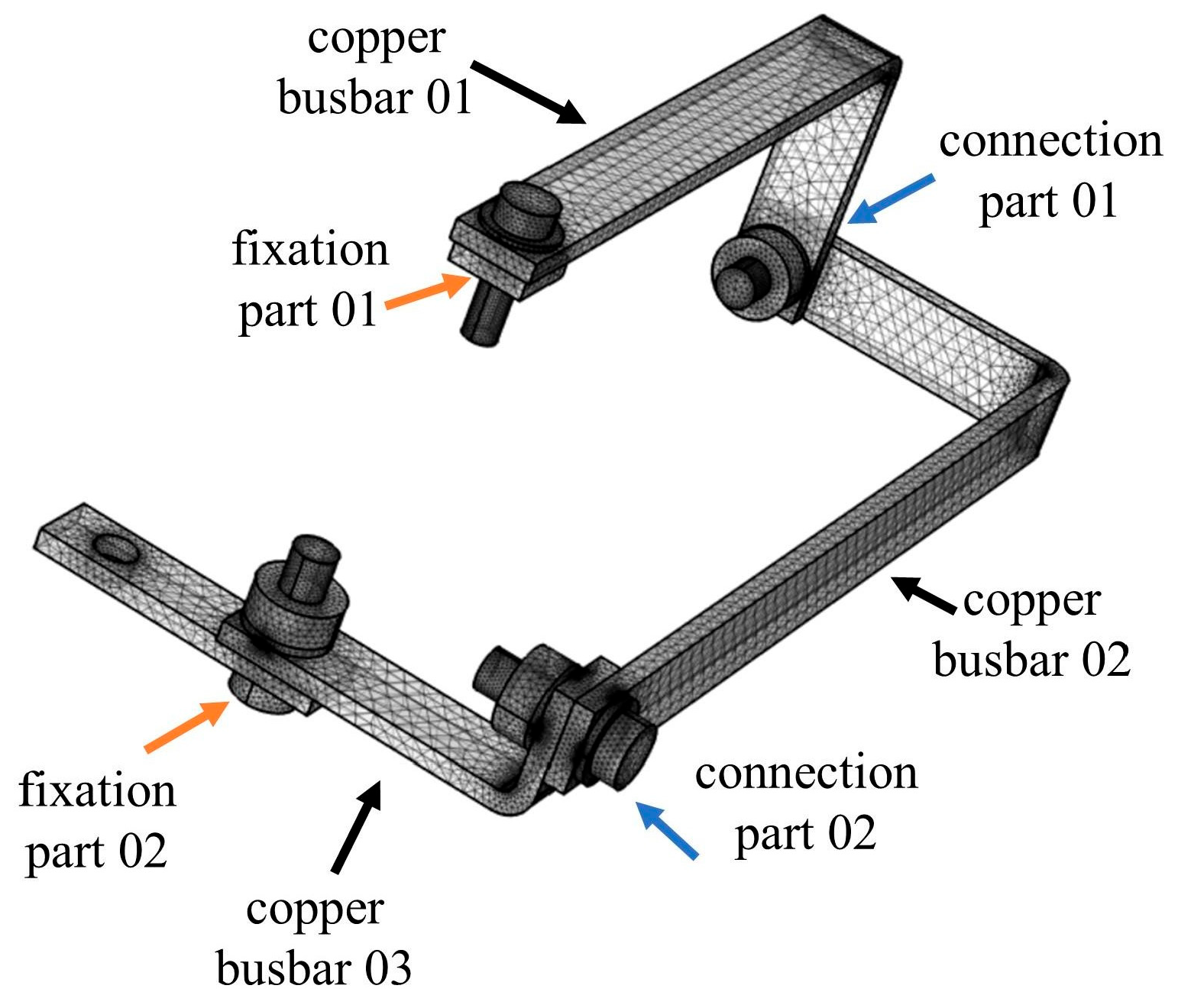
The poor electrical connection is most likely to arise at the bolt and screw opening of the green busbar. Consequently, modeling and analysis were performed on the temperature increase and displacement of the green busbar. AutoCAD was utilized to create drawings of busbars, bolts, gaskets, and other components to scale. The geometry model was subsequently loaded into COMSOL Multiphysics 6.3, as illustrated in Figure 3. Wire L2 comprised four bolted connectors. Two bolted connections secured either end of the conductor to the circuit breaker and the rear fixation plate, respectively. The remaining two bolts linked the busbars to wire L2.
(2)
Physical model
To simulate the material deformation and displacement resulting from overheating due to inadequate electrical contact of the busbar, it is essential to construct a physics model that integrates solid mechanics, heat transfer, and electrical fields. The thermal–electrical coupling has been demonstrated in [31]. Consequently, the material deformation induced by an increase in temperature can be incorporated into the framework of thermo-electrical coupling. The following part mainly addresses the establishment of the beginning and boundary conditions for the solid mechanics module.
In the solid mechanics module, the model is based on solving the equations of motion, together with a constitutive model for a solid material. Displacements, stresses, and strains were calculated. The initial conditions were set as follows. The initial displacement field and initial velocity field confirm that:
u = 0
u t = 0
where u is the displacement field.
The boundary conditions consist of a fixed constraint and a roller constraint. The busbars linked to the circuit breaker and the rear mounting plate are subject to fixed constraints. Their displacement is the zero vector. The other two bolts are subject to roller constraints. The bolts restrict displacement in a direction perpendicular to the boundary. The solid mechanics module is connected to the heat transfer module through thermal expansion.
Thermal expansion describes the deformation of the rigid connector resulting from temperature variations. Thermal stress represents the interaction between heat transfer and solid mechanics, as follows.
ε t h = α ( T T r e f )
where ε t h is the thermal stress, α is the secant coefficient of thermal expansion, and the reference temperature T r e f is 20 °C.
The module on electricity examines the poor electrical contact pair. Various local overheating situations were simulated by modifying the contact pressure and surface roughness. The initial temperature of the heat transfer module was set to 20 °C. It was assumed that the thermal convection between electrical components and the surrounding air was natural convection. Thus, all external surfaces of the electrical components were designated as natural convection interfaces. The natural convection coefficient of the interfaces was set to 5 kW/m2 [32].
(3)
Meshing and consistency check
The model uses the free tetrahedral mesh generated in COMSOL. The mesh size was controlled by modifying the mesh size. Five meshing schemes, including regular, fine, finer, super-fine, and finest meshes, were tested. The corresponding mesh numbers are shown in Table 1. The displacement along the y-axis and the maximum temperature of bolt 01 were calculated. The relative error between the finest mesh and the other four mesh schemes was calculated. It demonstrates that the solutions of the parameters, including displacement along the y-axis and temperature, are effectively converged. The relative error between the finer and finest mesh schemes can be within 0.53%. It turns out that the finer mesh can ensure accuracy and reduce the amount of calculation. Thus, the finer mesh was adopted in the following simulation calculation.
(4)
Parameter setup
The material of the busbar was set as copper. The material of the bolts was designated as stainless steel. The main physical parameters are listed in Table 2. The extent of poor electrical contact was adjusted by adjusting the contact pressure and the roughness of the contact surface. The contact pressure ranged from 10 Pa to 105 Pa. The roughness of the contact surface was set as 1.6 μm, 3.2 μm, 6.4 μm, 12.8 μm, 25 μm, and 50 μm [31]. The electrical current was set to 40 A at working status.

4.2. Result Analysis

(1)
Bolt 01 under poor contact
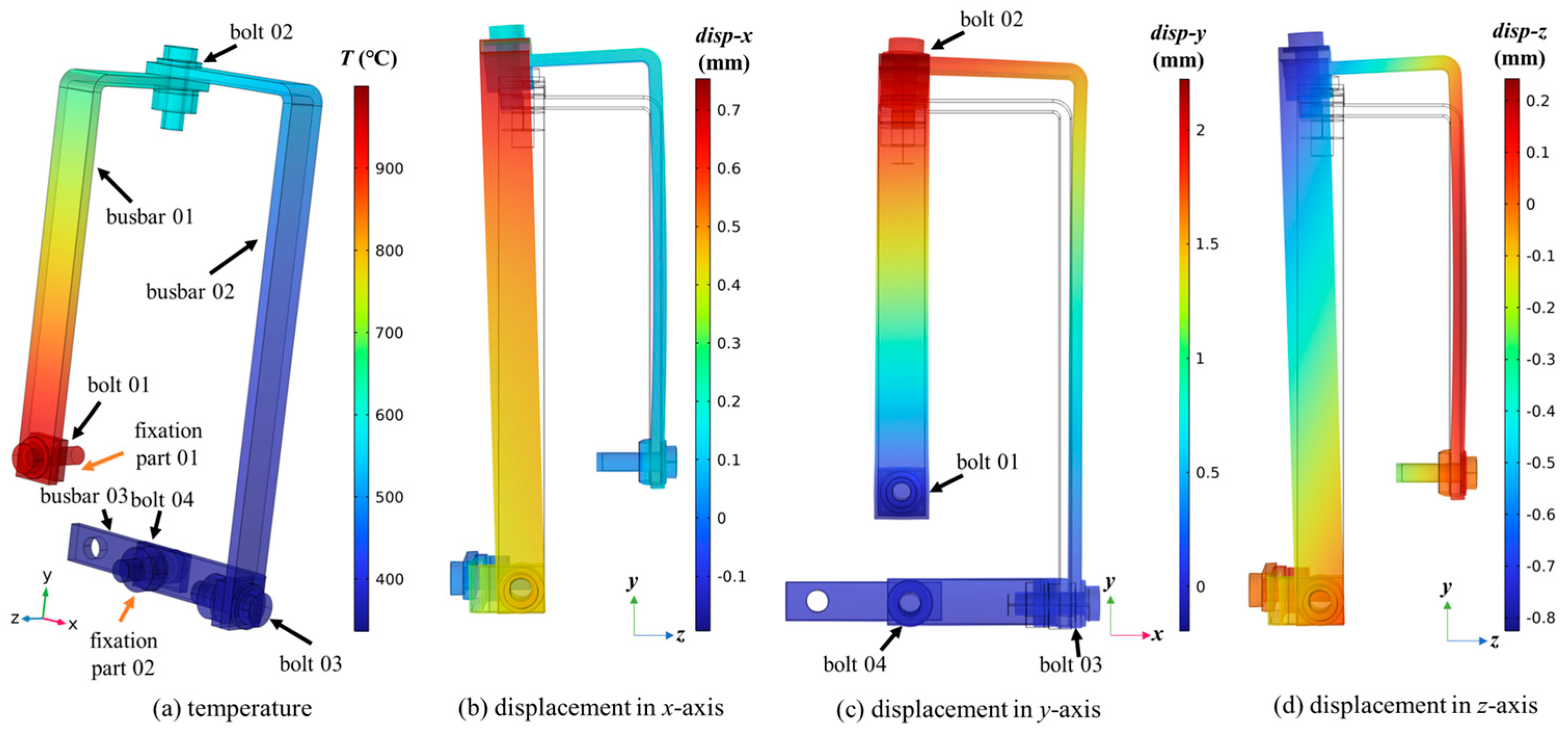
Figure 4 illustrates the temperature distribution and displacement of the busbars when bolt 01 is in a state of inadequate contact. At a contact pressure of 90 Pa and a surface roughness of 50 μm, the maximum temperature reached 1040 °C. The thermal stress generated by the uneven temperature distribution induced localized plastic deformation of busbar 01. The upper part of busbar 01 was deformed. The direction and characteristics of deformation aligned with the actual conditions outlined in Section 3.
The connection part 02 of wire L2 is fastened and crimped in a clockwise direction with respect to the vertical screen. Consequently, connection part 02 can restrict busbar 02 from descending. The upper section of busbar 01 tilts at bolt 01 as a hinge. Busbar 01 inclines outward in the vertical screen orientation, as shown in Figure 4b. Busbar 02 can mitigate the warping distortion of busbar 01 at bolt 03. The upper section of busbar 01 employs the extended arm of copper bar 02 (arm length 220 mm) as a lever, rotating anticlockwise outward along the vertical axis of the screen. The rotation direction aligns with the loosening direction of bolt 03. Consequently, the increase in temperature caused by the loose connection part 01 will exacerbate the poor contact at connection part 02.
(2)
Various bolts under poor contact
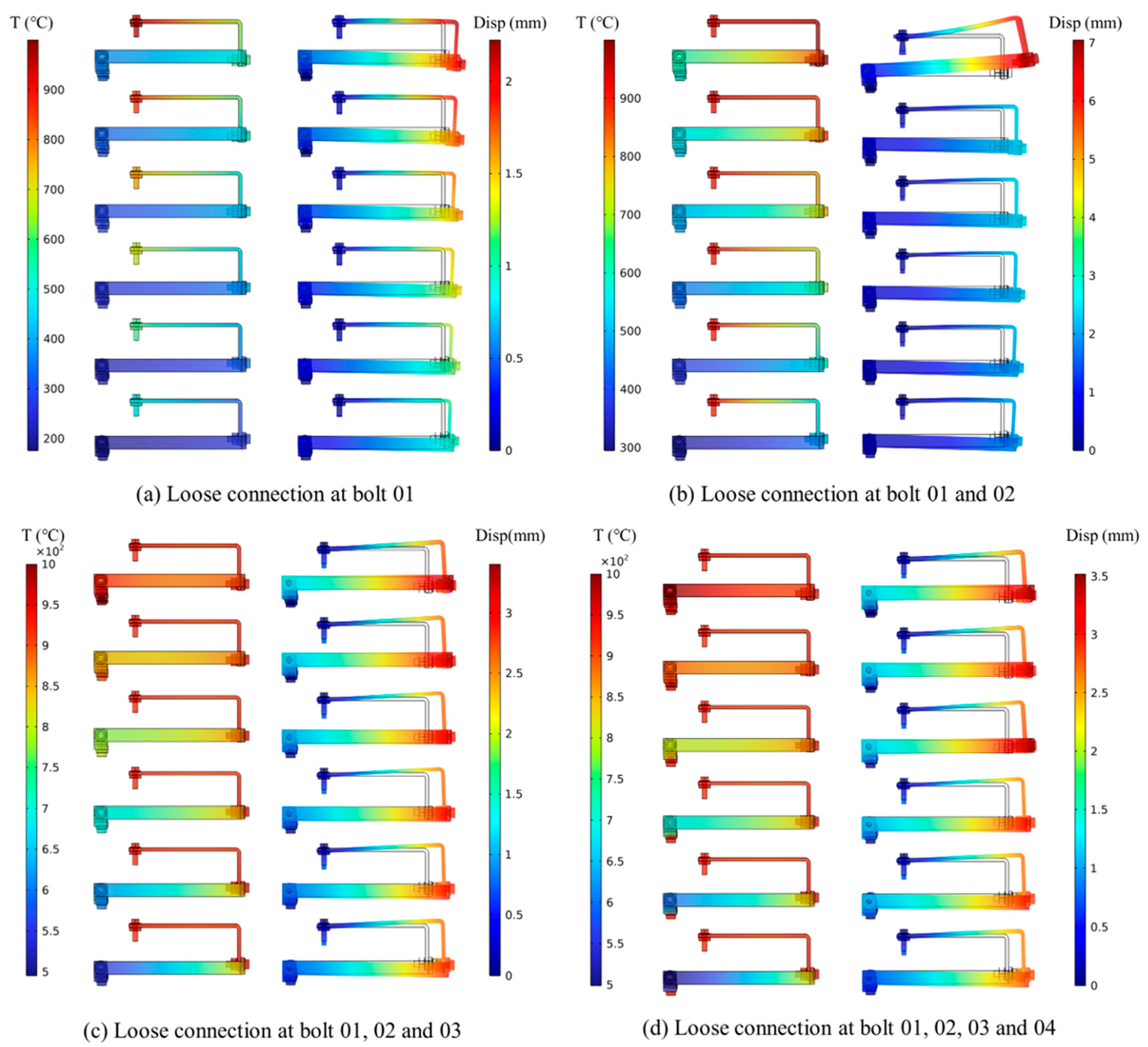
The preceding study revealed that inadequate contact of bolt 01 may lead to the loosening of nearby bolts. Consequently, multiple simulations of defective electrical contact bolts were run. Figure 5 illustrates the comparison of maximum displacement across several poor contact circumstances. The highest temperatures, from top to bottom, are 1040 °C, 943 °C, 834 °C, 769 °C, 667 °C, and 530 °C, respectively, in each subgraph.
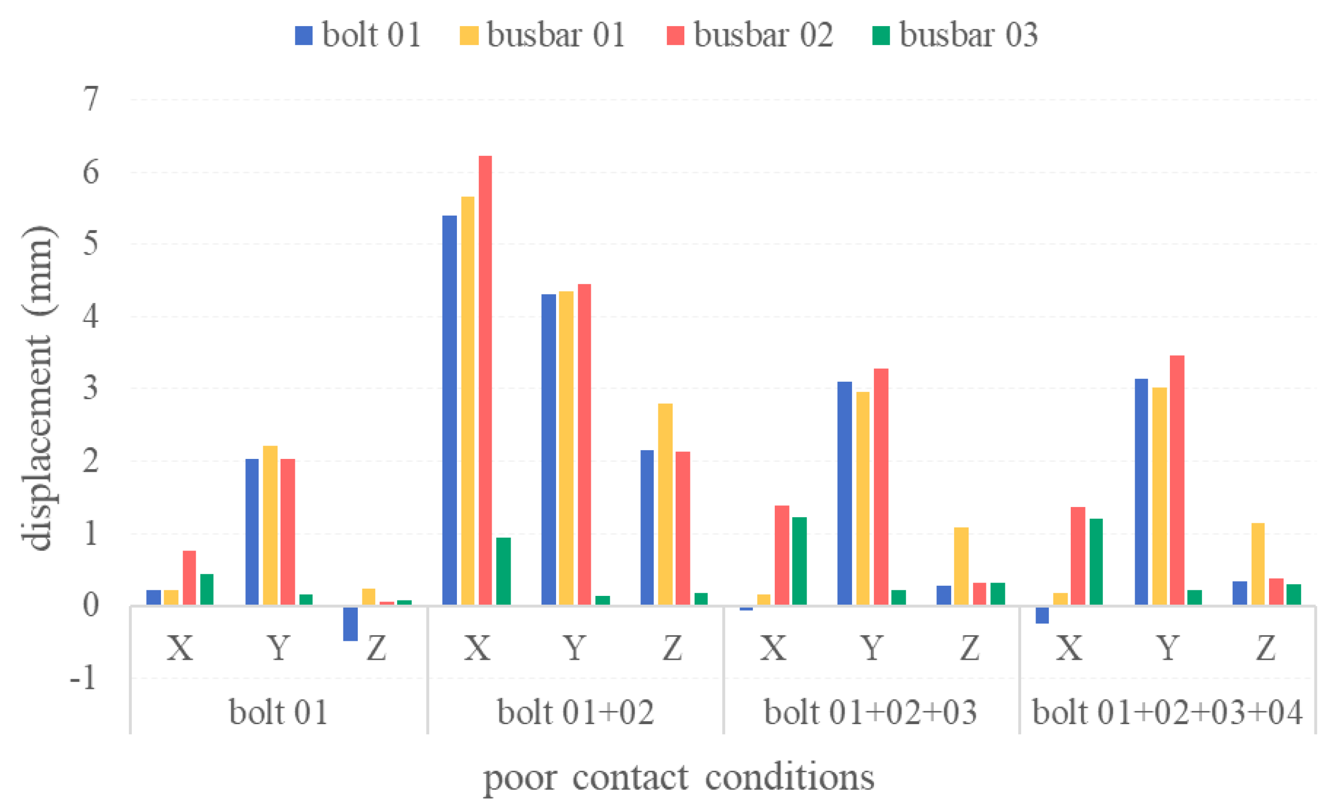
Figure 6 indicates that the displacement of bolt 01, busbar 01, and busbar 02 will grow along the x-, y-, and z-axes when bolt 01 and bolt 02 simultaneously exhibit inadequate contact. When only bolt 01 exhibits poor contact, the displacement of all components remains within 1 mm along the x- and z-axes. Nevertheless, it escalates to over 5 mm along the x-axis and exceeds 2 mm along the z-axis. The displacement along the y-axis is doubled when bolts 01 and 02 are in inadequate contact.
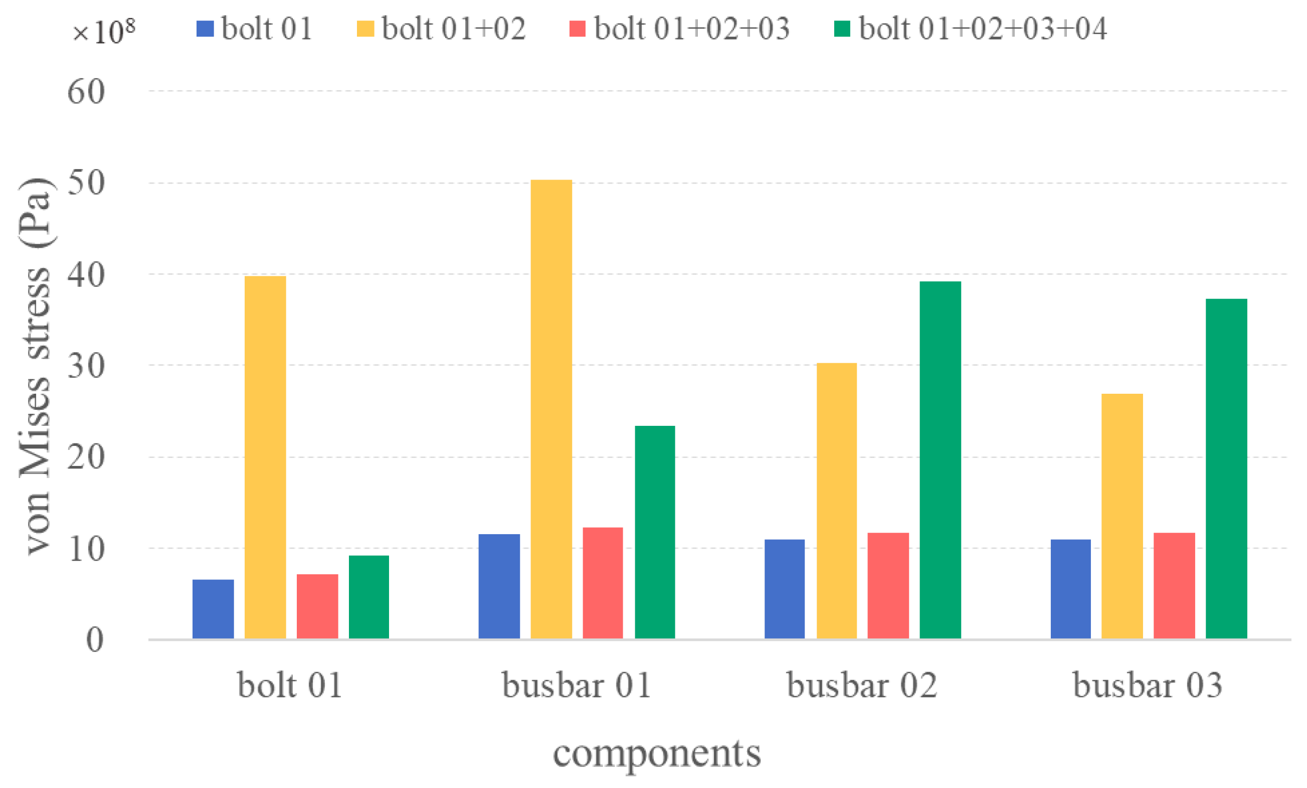
When bolts 01, 02, 03, and 04 exhibit poor contact, the displacement of the busbar increases compared to the condition where just bolt 01 is in bad contact. Nonetheless, the displacement of the four bolts under inadequate contact is approximately half of the displacement observed when bolts 01 and 02 suffer bad contact. This can be understood as follows. The temperature distribution irregularity on the wire induced thermal stress. The stress causes deformation and displacement of the busbar. Figure 7 illustrates the Von Mises stress under various situations. It shows that the peak stress is observed on bolt 01, busbar 01, and busbar 02 when bolt 01 and bolt 02 exhibit poor contact. The maximal Von Mises stress with bolt 01 under poor contact is 1.15 × 10⁹ Pa, while the maximal Von Mises stress is 5.04 × 10⁹ Pa when bolt 01 and bolt 02 exhibit poor contact.
IEC 60695-1-14 provides guidance on the different levels of power and energy related to the probability of ignition and fire in low-voltage electrotechnical products. The two curves in Figure 8 are separated into three zones, namely, class 1, class 2, and class 3. The maximum powers on the busbars are 92 W, 105 W, 118 W, 131 W, 144 W, and 157 W, corresponding to the maximum temperatures of 530 °C, 667 °C, 769 °C, 834 °C, 943 °C, and 1040 °C, respectively. The circuit breaker does not operate when poor contact exists, so that the overheating can last for a long time. Figure 8 shows that all the conditions in the class 3 zone are sustained for 6 s after overheating. This means that ignition and a subsequent fire are likely if a fault occurs [33].

5. Force Model and Comprehensive Analysis

5.1. Force Model

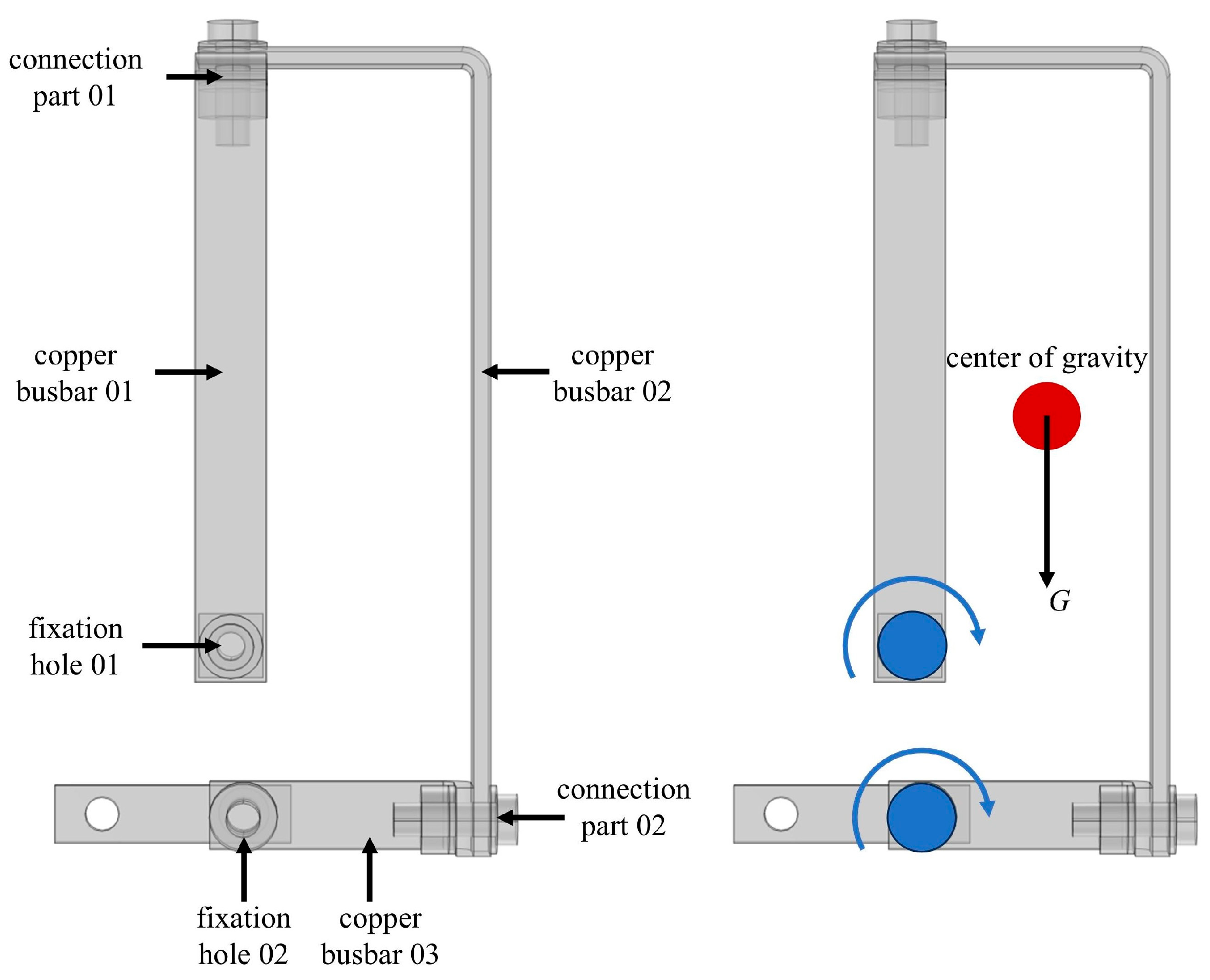
To elucidate the mechanism of wire L2’s deflection to the right, a simplified force analysis model was built, as illustrated in Figure 9. Factors influencing the vertical screen orientation were simplified. The configuration of wire L2 is roughly rectangular. Wire L2 contains two fixing holes. The fastening bolts secure the wire through the fixation hole 01 and hole 02. The center of gravity of wire L2 is approximately located at a point at the center of the rectangle, as indicated by the red circle in Figure 9. The two fixation holes, which are represented by two blue circles, can be served as hinge joints for rotation.
The simulation results in Section 4.2 indicate that wire L2 exhibits inadequate contact at bolt 01 and bolt 02, leading to localized heat accumulation on busbar 01. The irregular temperature distribution induced localized deformation of wire L2 due to thermal stress. Consequently, the upper portion of wire L2 was elevated. The tilting of the top of wire L2 induced displacement and deformation between busbar 01 and busbar 02. Furthermore, it exacerbated the inadequate contact and thermal accumulation at bolt 03 concurrently. The upper section of wire L2 was elevated to eliminate the slack at bolt 03. Consequently, the joule heat generated at bolt 03 resulted in localized plastic deformation of busbar 03.
The distance from the connection part 02 of wire L2 to the fixation part 02 is 67 mm. Copper possesses excellent thermal conductivity, allowing the localized overheating at the connection point 02 to be continually transferred to the fixation part 02. This resulted in the loose connection of the fixation part 02.
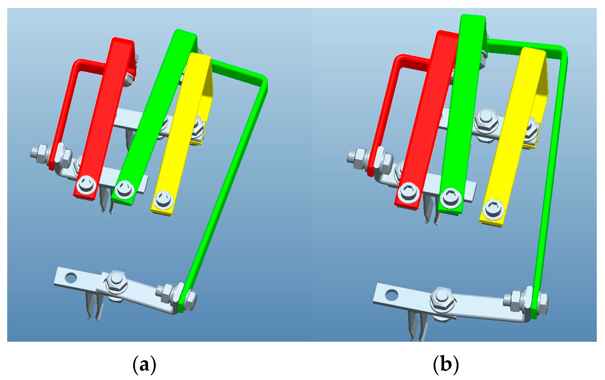
Upon the loose contact at fixation part 01 and fixation part 02, wire L2 persisted in its rightward deflection due to gravitational forces. Bolt 02 at the top of wire L2 made contact with wire L1, resulting in a short circuit, as seen in Figure 10a. The simultaneous effects of electric repulsion due to the short circuit and gas expansion from electrical arcs caused wire L2 to deflect to the left, as illustrated in Figure 10b. The left-shifted wire L2 made contact with wire L3, resulting in a short circuit. Likewise, the electric repulsion force and the expansion of high-temperature gas caused wire L2 to return to the right side and re-establish contact with wire L1. Although wire L2 bends to the left without contacting wire L3, it will persist in bending to the right due to its own gravitational force. This causes another short circuit between the fixing bolt at the top of wire L2 and wire L1.

5.2. Comprehensive Analysis

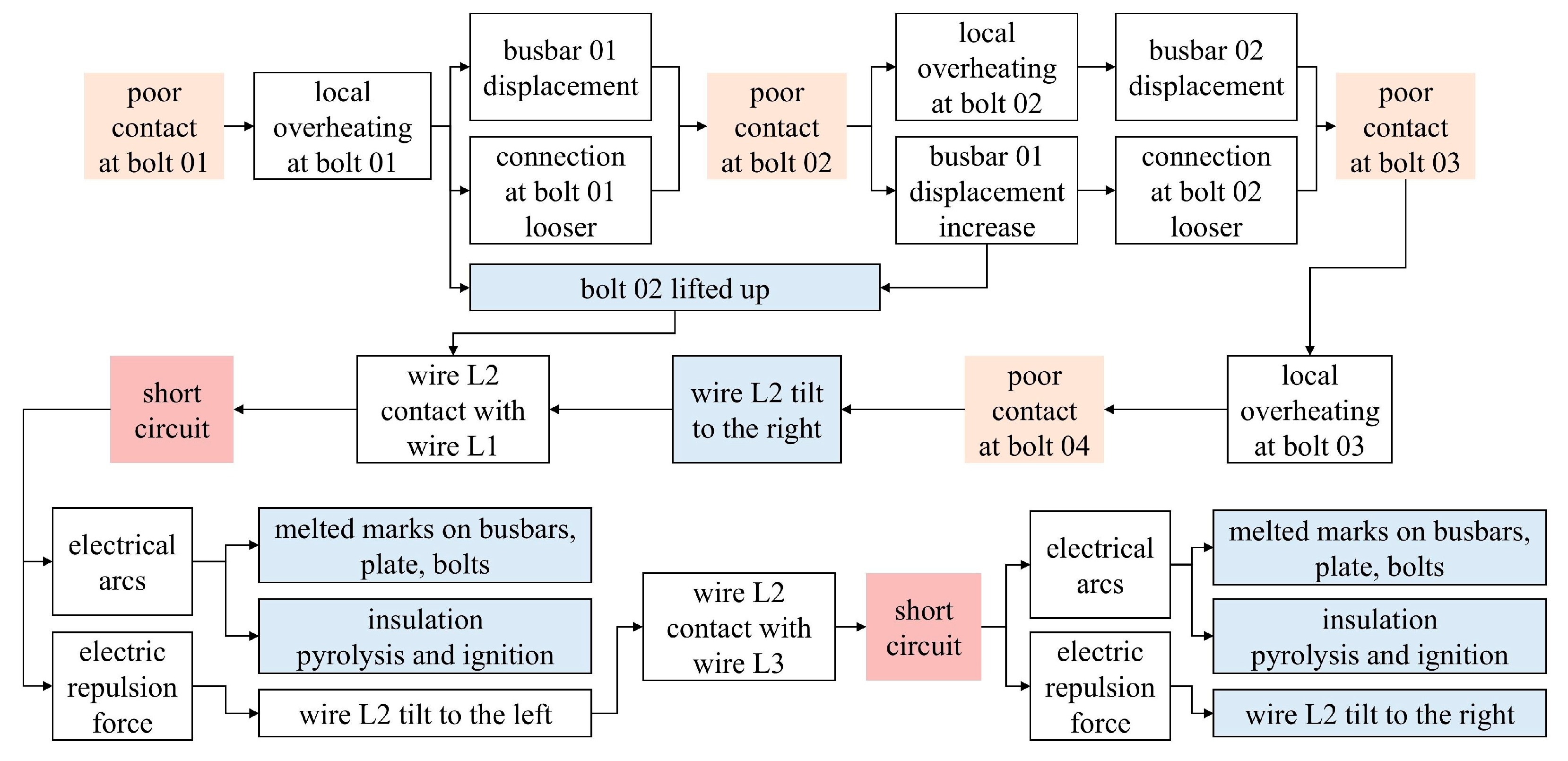
The evidence chain can be constructed as shown in Figure 11. The process of the electrical cabinet fire can be restored through forward deduction. The whole process can be divided into two stages, including the transmission of poor contact and a short circuit. In the first stage, bolt 01, which is the connection between busbar 01 and the circuit breaker, has poor contact initially. The overheating at bolt 01 caused the displacement of busbar 01 and lifted bolt 02. The movement of bolt 01 made the loose connection at bolt 02. The overheating at bolt 02 increased the displacement of busbar 01 and busbar 02. Thus, bolt 01 continued to be lifted and worsened the good contact at bolt 03. The overheating at bolt 03 further caused poor contact at bolt 04.
The next stage is the short circuit. Since the four connecting bolts are loose, the busbar of wire L2 continued to shift to the right under gravity. Therefore, the lifted bolt 02 of wire L2 came into contact with the top of wire L1. A short circuit was triggered, accompanied by electrical arcs. High-temperature arcs melted the contact conductors and produced molten beads. The splashing arcs and beads attached to the surrounding objects, including conductors, bolts, and the steel plate. The high temperature caused the pyrolysis and ignition of the insulation. Meanwhile, the electric repulsion force generated by the contact of live conductors between different phases caused wire L2 and wire L1 to separate. Therefore, wire L2 tilted to the left and came into contact with wire L3. Similarly, the contact between wire L2 and wire L3 triggered a short circuit. The electrical arcs continued to melt the conductor and promoted the pyrolysis and ignition of insulation materials. The electric repulsion force pushed wire L2 to the right again. The smoke generated by the pyrolytic insulating material adhered to conductors, escaped from the cabinet, and adhered to the upper half of the cabinet surface.
After finding out the cause of the electrical cabinet fire, it is also important to put forward practical preventive measures. First, it is imperative to verify the consistency of bolt sizes and screw hole diameters during the design, installation, and validation phases. Second, in addition to the heat-shrinkable tube insulation layers wrapped in the outer surface of the busbar, insulation isolation should be set between different phases of busbars to prevent a direct-contact short circuit triggered by wire displacement.

6. Conclusions

This paper establishes a fire investigation methodology for electrical cabinet fires. A cabinet fire case is analyzed according to the investigation procedure. Trace analysis, Multiphysics simulation, and force analysis are employed to investigate the origin of electrical fires. The principal conclusions are as follows.
(1) The proposed electrical cabinet fire investigation methodology consists of three primary phases: evidence collection and reason inference, reverse deduction, and complete analysis. A fire is selected as an example resulting from poor electrical contact at the bolt connection. The typical trace features of electrical cabinet fires encompass melted markings on bolts, busbars, and adjacent fixation steel plates. The busbar, which belongs to the live wire, exhibits a noticeable displacement.
(2) A thermal–electrical–mechanical coupling model is developed to simulate the displacement of the busbar. The elevated temperature resulting from the poor contact part can reach 1040 °C. The calculation results show that the busbar exhibits a maximum displacement of 6.2 mm when two bolts are in a poor contact condition. The displaced busbar will come into contact with different phases of the busbar, resulting in a short circuit due to the absence of insulation material between various phases of the busbars.
(3) The simulation reveals the transmission effect of poor contact on bolt connection. The results reveal that overheating and the displacement of a loose connection on one bolt will exacerbate the poor connection of the adjacent bolt. When two bolts have poor contact, the maximum thermal stress on the busbar can reach 5.04 × 10⁹ Pa, which is 4.38 times higher than when only one bolt has poor contact. Higher thermal stress will promote the displacement of the bolts and busbars and deteriorate the poor contact conditions. Eventually, all the bolt connections on the busbar will begin to fail. It results in deformation and displacement, with localized overheating zones intensifying.
The fire investigation findings on the electrical cabinet indicate that wires from various phases will experience short circuits due to inadequate electrical contact. The insufficient contact stemmed from the discrepancy between the size of the bolt and that of the screw hole. Therefore, the consistency of bolt sizes and screw hole diameters should be checked by installation, inspection, and maintenance personnel. Additionally, insulation walls between busbars of different phases should be built to avoid short circuits caused by the displacement of the wire. This study only uses one electrical cabinet fire caused by poor contact as an example to study the methods of fire investigation and analysis. In the future, this method should be applied to more practical case studies for verification and validation.

Supplementary Materials

The following supporting information can be downloaded at: https://www.mdpi.com/article/10.3390/fire8110412/s1, Figure S1: Circuit breakers and wire connections; Figure S2: Appearance of electrical cabinet after fire; Figure S3: Melting marks of busbars after fire; Figure S4: Bolts and screw holes of copper busbar; Figure S5: Connection surface between L2 copper busbar 3 and terminal of plug-in box.

Author Contributions

Conceptualization, J.Z.; methodology, G.S. and W.M.; formal analysis, J.Z. and C.L.; investigation, J.Z., C.L. and W.M.; writing—original draft preparation, J.Z. and C.L.; writing—review and editing, G.S.; supervision, G.S.; funding acquisition, G.S. All authors have read and agreed to the published version of the manuscript.

Funding

This research was funded by the National Key Research and Development Program of China (No. 2024YFC3016800) and the China Postdoctoral Science Foundation (Grant No. 2024M751713). The APC was funded by the National Key Research and Development Program of China (No. 2024YFC3016800).

Data Availability Statement

The original contributions presented in this study are included in the article/Supplementary Materials. Further inquiries can be directed to the corresponding author(s).

Conflicts of Interest

The authors declare no conflicts of interest.

References

  1. Meng, H.; Xiao, L.; Zhang, C.; Zhang, T.; Xia, D.; Dong, W. A Systematic Review and Bibliometric Analysis of Electrical Fires from 1993 to 2022. Fire Technol. 2024, 60, 3347–3377. [Google Scholar] [CrossRef]
  2. Li, C.; Zhang, Y.; Tang, K.; Yuan, D. Coupled effects of the internal and external heat sources on flame spread behaviors over wires in a real building fire scenario. J. Build. Eng. 2025, 105, 112416. [Google Scholar] [CrossRef]
  3. Xinhua News Agency; Zhou, Y.; Zhang, Q. The Overall Fire Situation in China Will Remain Stable in 2024. 2025. Available online: https://www.xinhuanet.com/politics/20250124/65bd956b37f241f68399eec554fc64e8/c.html (accessed on 9 September 2025).
  4. U.S. Fire Administration. Fire and Fire Loss Data from NFIRS. 2023. Available online: https://www.usfa.fema.gov/statistics/data-sets/ (accessed on 9 September 2025).
  5. Government of Guizhou Province Accident Investigation Team. Investigation Report on the “8 · 18” Major Fire Accident at Dream Zhaoxing Inn in Liping County, Qiandongnan Autonomous Prefecture; The People’s Government of Guizhou Province. 2023. Available online: https://yjgl.guizhou.gov.cn/yjzhxxwmh/yq/sgxx_5851269/202410/P020241015615793804114.pdf (accessed on 9 September 2025).
  6. Li, D.; Zhong, Y.; Zhou, X.; Zhai, G. A simulated experimental system and risk prediction method for ignition caused by overhead lines short-circuit. J. Mech. Sci. Technol. 2023, 37, 6493–6501. [Google Scholar] [CrossRef]
  7. Huo, Y.; Xu, X.; Li, Y.; Li, R.; Yu, Z.; Wang, W. Experimental and theoretical research on the temperature evolution law of overcurrent fault wires. Fire Mater. 2024, 48, 632–641. [Google Scholar] [CrossRef]
  8. Li, Y.; Sun, Y.; Gao, Y.; Sun, J.; Lyu, H.-F.; Yu, T.; Yang, S.; Wang, Y. Analysis of overload induced arc formation and beads characteristics in a residential electrical cable. Fire Saf. J. 2022, 131, 103626. [Google Scholar] [CrossRef]
  9. Jia, Y.; Man, P.; Guo, X.; Deng, L.; Li, Y. Effects of Overload on Thermal Decomposition Kinetics of Cross-Linked Polyethylene Copper Wires. Polymers 2023, 15, 3954. [Google Scholar] [CrossRef]
  10. Li, C.; Yang, Z.; Yao, W.; Zou, K.; Liu, H.; Lin, J.; Lu, S. Experimental study of ignition process caused by poor electrical contact of connecter. Process. Saf. Environ. Prot. 2024, 189, 1517–1526. [Google Scholar] [CrossRef]
  11. Gao, Z.; Yang, R.; Yang, W.; Yao, Y.; Wang, J. Study on arc duration and erosion characteristics of cable electrodes in AC series circuits. J. Phys. D Appl. Phys. 2023, 56, 375201. [Google Scholar] [CrossRef]
  12. Kang, N.; Zhao, Z.; Lin, J.; Lu, S. Ignition of silicone rubber sheaths by series arcs at different currents and durations. Fire Saf. J. 2023, 136, 103753. [Google Scholar] [CrossRef]
  13. Tomoyasu, I.; Michael, R.K.; Yasuaki, H.; Sugawa, O. Leakage Currents Precede Short Circuits in PVC-Insulated Cable When Exposed to External Radiant Heat. Fire Mater. 2017, 41, 339–348. [Google Scholar] [CrossRef]
  14. John, D.D.; David, J.I. Kirk’s Fire Investigation, 7th ed.; Pearson: Hoboken, NJ, USA, 2012. [Google Scholar]
  15. Ge, F.; Qiu, T.; Zhang, M.; Ji, J. Experimental research on the thermal characteristic of low-voltage alternating current (AC) arc faults. Fire Saf. J. 2022, 136, 103732. [Google Scholar] [CrossRef]
  16. Zhang, M.; Ge, F.; Ji, J. Experimental Research on Heat Transfer and Ignition Characteristics of Series Fault Arc Combustion in 220VAC Power System. Combust. Sci. Technol. 2023, 197, 1100–1119. [Google Scholar] [CrossRef]
  17. Yu, F.; Wang, S.; Tang, K.; Lin, Y.; Wang, S.; Zhang, Y. Research Progress on the Fire Characteristics of Electric Cables and Wires. Fire 2024, 7, 186. [Google Scholar] [CrossRef]
  18. Plumecocq, W.; Coutin, M.; Melis, S.; Rigollet, L. Characterization of closed-doors electrical cabinet fires in compartments. Fire Saf. J. 2011, 46, 243–253. [Google Scholar] [CrossRef]
  19. Coutin, M.; Plumecocq, W.; Zavaleta, P.; Audouin, L. Characterisation of open-door electrical cabinet fires in compartments. Nucl. Eng. Des. 2015, 286, 104–115. [Google Scholar] [CrossRef]
  20. Bryant, R.; Bundy, M. The NIST 20 MW Calorimetry Measurement System for Large-Fire Research, Technical Note (NIST TN) 2077. NIST; 2019. Available online: https://nvlpubs.nist.gov/nistpubs/TechnicalNotes/NIST.TN.2077.pdf (accessed on 9 September 2025).
  21. Pascal, Z.; Sylvain, S. Experimental Study in Open Atmosphere and Confined Conditions of Fire Spread between Adjacent Electrical Cabinets Connected by Cabe Trays. Fire Saf. J. 2023, 140, 103872. [Google Scholar] [CrossRef]
  22. Pascal, Z. Experimental study at reduced-scale of fire spread between electrical cabinets located opposite each other. Fire Saf. J. 2021, 122, 103319. [Google Scholar] [CrossRef]
  23. Ma, Q.; Chen, Z.; Chen, J.; Du, M.; Sun, Y.; Chen, N. A predictive model for centerline temperature in electrical cabinet fires. Renew. Sustain. Energy Rev. 2024, 211, 115303. [Google Scholar] [CrossRef]
  24. Shu, S.-B.; Chuah, Y.K.; Lin, C.-J. A study on the spread of fire caused by the stack effects of patio—A computer modeling and a reconstruction of a fire scenario. Build. Simul. 2012, 5, 169–178. [Google Scholar] [CrossRef]
  25. National Fire Protection Association. NFPA 921: Guide for Fire and Explosion Investigations, 2017 Edition. National Fire Protection Association. 2017. Available online: https://www.nfpa.org/product/nfpa-921-guide/p0921code (accessed on 9 September 2025).
  26. GB/T 16840.2-2021; Technical Determination Methods for Electrical Fire Evidence, GB. Standards Press of China: Beijing, China, 2021.
  27. Wang, W.; Zhao, X.; Liu, Q.; Ji, X.; Yang, Z.; Gui, X.; Li, Z.; Wang, L. Study on quantitative metallographic analysis method of copper wire melt trace under short-circuit and fire conditions. J. Therm. Anal. Calorim. 2023, 148, 12145–12158. [Google Scholar] [CrossRef]
  28. Park, J.; Kang, J.-H.; Lee, E.P.; Ko, Y.H.; Bang, S.B. New Approach to Distinguish Copper Molten Marks Based on Quantitative Microstructure Analysis Using Electron Backscatter Diffraction. Fire Technol. 2021, 57, 1667–1682. [Google Scholar] [CrossRef]
  29. Zhang, J.; Chen, T.; Su, G.; Li, C.; Zhao, F.; Mi, W. Microstructure and component analysis of glowing contacts in electrical fire investigation. Eng. Fail. Anal. 2022, 140, 106539. [Google Scholar] [CrossRef]
  30. Wang, W.; Lu, C.; Shi, L.; Lyu, H.; Ji, X.; Huo, Y. Numerical simulation and experimental study on metallographic structure characteristics of melting trace caused by overcurrent fault of copper wire. J. Loss Prev. Process. Ind. 2023, 83, 105065. [Google Scholar] [CrossRef]
  31. Zhang, J.; Huang, L.; Chen, T.; Su, G. Simulation based analysis of electrical fire risks caused by poor electric contact between plug and receptacle. Fire Saf. J. 2021, 126, 103434. [Google Scholar] [CrossRef]
  32. Incropera, F.P.; Lavine, A.S.; Bergman, T.L.; DeWitt, D.P. Fundamentals of Heat and Mass Transfer; Wiley: Hoboken, NJ, USA, 2007. [Google Scholar]
  33. IEC, TS 60695-1-14:2017; Fire Hazard Testing. Part 1–14: Guidance on the Different Levels of Power and Energy Related to the Probability of Ignition and Fire in Low Voltage Electrotechnical Products. Internation Electrotechnical Commission: Geneva, Switzerland, 2017.
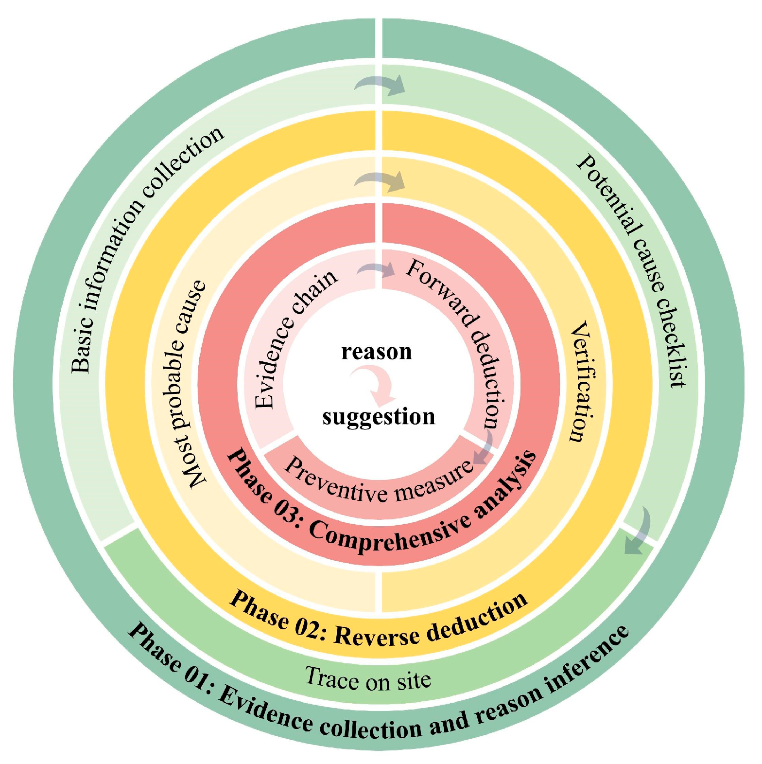
Figure 1. Methodology of electrical cabinet fire investigation.
Fire 08 00412 g001
Figure 2. Component analysis of the steel plate and its attachments.
Fire 08 00412 g002
Figure 3. Geometry and meshing of the busbar in COMSOL.
Fire 08 00412 g003
Figure 4. Temperature rise and displacement along the xyz-axis. (a) Temperature, (b) displacement along the x-axis, (c) displacement along the y-axis, and (d) displacement along the z-axis.
Fire 08 00412 g004
Figure 5. Simulation results under different loose connection conditions. (a) Loose connection at bolt 01. (b) Loose connection at bolts 01 and 02. (c) Loose connection at bolts 01, 02, and 03. (d) Loose connection at bolts 01, 02, 03, and 04.
Fire 08 00412 g005
Figure 6. Comparison of the maximum displacement under various poor contact conditions.
Fire 08 00412 g006
Figure 7. Maximum Von Mises stress under different conditions.
Fire 08 00412 g007
Figure 8. Electrical power under different conditions. (The blue line is the dividing line of Class 1 and Class 2. The yellow line is the dividing line of Class 2 and Class 3).
Fire 08 00412 g008
Figure 9. Force analysis schematic.
Fire 08 00412 g009
Figure 10. Diagram of L2 (green) wire swinging to the right and left. (a) Wire L2 deflects to the right. (b) Wire L2 deflects to the left.
Fire 08 00412 g010
Figure 11. Evidence chain of one cabinet fire.
Fire 08 00412 g011
Table 1. Meshing scheme and relative error evaluation.
Mesh SchemeDisplacement Along the y-Axis (mm)Relative ErrorTemperature (°C)Relative ErrorNumber of Meshes
finest2.2299/554.39/340,766
super-fine2.23690.31%554.40.00%111,864
finer2.24170.53%554.410.00%44,700
fine2.24330.60%554.450.01%19,154
regular2.25531.14%554.510.02%7731
Table 2. Physical parameter setup.
ParameterUnitCopperStainless Steel
Electrical conductivityS/m6.00 × 1074.03 × 107
Coefficient of thermal expansion1/K1.70 × 10−51.23 × 10⁻⁵
Constant pressure heat capacityJ/(kg·K)385475
Densitykg/m389607850
Thermal conductivityW/(m·K)40044.5
Young’s modulusPa1.10 × 10112.00 × 1011
Poisson’s ratio10.350.30
Disclaimer/Publisher’s Note: The statements, opinions and data contained in all publications are solely those of the individual author(s) and contributor(s) and not of MDPI and/or the editor(s). MDPI and/or the editor(s) disclaim responsibility for any injury to people or property resulting from any ideas, methods, instructions or products referred to in the content.