Abstract
To investigate the combustion characteristics of multiple fire sources in the tunnel caused by ‘jumping’ discontinuous fire spread, we utilized scaled model experiments, numerical simulation software, and theoretical research. Our study focused on analyzing the influence of different fire source powers on the temperature characteristics of double fire sources in the tunnel. We examined the temperature characteristics, critical wind speed, and change rule under various wind speeds, fire source spacing, and fire source powers. Additionally, we explored the temperature characteristics, critical wind speed, and change rule of different fire source powers under varying wind speed conditions. The mathematical model for roof temperature decay and the temperature decay coefficients of dual source fires were established through the analysis of scale-down model experiments and numerical simulations. In comparison to single-source fires, the temperature variations in the tunnel of dual source fires exhibit a more intricate pattern, with higher average temperature and temperature peak values. These values are influenced by factors such as fire source spacing and power. Numerical simulation software was utilized to investigate the impact of fire source spacing at 10 m, 15 m, and 20 m, as well as the effect of varying fire source power on the temperature distribution within a tunnel under consistent fire source position and growth coefficient. The study revealed that, with consistent double fire source position and ventilation conditions in the tunnel, the upstream fire source exhibited greater power than the downstream fire source, resulting in the lowest average and peak temperatures in the tunnel. This observation could potentially enhance escape and rescue operations within the tunnel. Similarly, the lowest average and peak temperatures in the tunnel were also identified, offering potential benefits for optimizing escape and rescue strategies in tunnel scenarios.
1. Introductory
Mine fires, as one of the five major mine disasters, have been extensively studied by scholars worldwide. Approximately 60% of mine fires are exogenous fires, commonly caused by factors such as tape fires resulting from prolonged friction between the tape and bottom rollers or the burning of accumulated coal layers. Following a tape fire, the confined space within the tunnel causes a rapid rise in temperature. The wind flow within the tunnel can cause the flame to deflect at an angle [1,2]. The heat radiation from the deflected flame front onto the tape below it may result in ‘jumping’ non-continuous fire spread, leading to the formation of two or even more fire sources [3,4]. This can result in a chain of accidents. Compared to a single fire source, the temperature change and smoke spread of a double fire source are more complex. As a result, the emergency response plan for a double fire source will differ from that of a single fire source. Therefore, it is crucial to investigate the combustion characteristics of double ignition sources in tunnels, analyze the disaster mechanisms involved, and develop appropriate fire rescue and evacuation plans for underground scenarios.
Researchers both domestically and internationally have conducted studies on fires in confined spaces using scaled-down model experiments in conjunction with computer numerical simulation software. Liu [5] and colleagues investigated the air entrainment restriction mechanism between fire sources through fire experiments and detailed the outcomes of air competition between two fire sources. Yu Minggao [6] conducted a numerical simulation study on the critical wind speed of double fire sources in enclosed spaces. The research concluded that the critical wind speed of double fire sources is inversely related to the distance between the sources. Additionally, it was found that the critical wind speed of double fire sources is higher than that of single fire sources when the total area of the double fire source is larger. Liu Qiong [7] investigated the double fire source issue in tunnels by using computer simulation software and previous reduced scale model experiments. The research focused on the kinetic energy change of smoke microgroups from the upstream fire source, providing an expression for the critical wind speed of double-fire sources. Cui Xinyuan [8] studied the double fire source fire through scaled-down model experiments and FDS numerical simulation software. The research examined the relationship between fire source surface width and nearby temperature, finding a negative correlation between the width of the fire source and the temperature nearby. Tsai [9] conducted numerical simulations to investigate the characteristics of double-fire source fires, determining that the critical wind speed is influenced by factors such as fire source spacing and location. Guo Chao [10] conducted full-scale model experiments to analyze the tunnel fire characteristics of double fire sources. By examining parameters such as heat release rate (HRR), temperature variations, CO concentration changes, and ignition mechanisms of double fire sources, it was concluded that the downstream temperature decay of twin sources follows an exponential decay pattern. Xu Haozhen [11] investigated the mass loss flow rate of dual fire sources during combustion using scaled-down model experiments and numerical simulation software. The study revealed that the mass loss flow rate of dual fire sources is comparable to that of a single fire source. Additionally, a negative correlation was observed between the spacing of fire sources and the mass loss flow rate during the stable phase of fire combustion. Literature [12,13,14,15,16] and other researchers have developed reduced-scale models and utilized computer simulation software to investigate the impact of critical wind speed on a single fire source and the spacing of a double fire source. Their findings suggest a quadratic decrease in critical wind speed with an increase in fire source spacing, particularly in cases where the limiting distance is considered. Liu [17] conducted interference experiments on two parallel ignition source fire plumes, examining the influencing factors between the two fire zones. They identified three flame interaction zones and five interaction states. In a separate study, Haukur Lngason [18] and colleagues investigated the correlation between various fire conditions and longitudinal ventilation using scaled-down modeling experiments. They suggested the application of dimensionless correlations to predict the temperature distribution of the roof downstream of the fire source. Oka et al. [19] conducted experiments on tunnels to study the effect of fire source location on critical wind speed. Additionally, scholars [20,21,22,23,24] examined temperature attenuation for a double fire source, developed a temperature attenuation model, and validated it using a scaled-down model. Numerous scholars have conducted extensive research on the combustion mechanism of dual fire sources however, there is a lack of studies focusing on dual fire sources with varying powers. In comparison to a single fire source, the average temperature within a tunnel containing dual fire sources is expected to be notably higher, attributed to the unique characteristics of fire combustion and the specific number and power of fire sources. Furthermore, the diversity in the location and power of fire sources plays a significant role in shaping the escape environment for individuals.
Different firepower scenarios involving dual fire sources can significantly impact the escape environment for individuals on roadways. Analyzing the parallel combustion mechanisms of various firepower configurations will enhance our understanding of their disaster mechanisms. This research will inform the development of emergency escape plans, providing a theoretical foundation for effectively addressing fires involving multiple sources in tunnels. Meanwhile, the influence of multi-source fires with different ignition powers on the temperature distribution of the tunnel was analyzed. By combining previous research with experiments conducted at a mine in Shanxi, a fire scaling model was developed. The study utilized Pyrosim numerical simulation software to investigate the combustion characteristics of double fire sources in tunnels. The research focuses on the factors and effects of different fire source spacing and different fire source power on the temperature change of the personnel escape environment under the dual fire source condition of a parallel combustion mechanism. This study contributes to providing a theoretical basis for disaster management of double and multiple fire sources in tunnels.
2. Dual-Source Fire Experiment
2.1. Determination of Model Construction Parameters
In order to study the fire characteristics of the dual ignition source, the scaled-down model of the tunnel was established, and the relevant parameters of the model are shown in Table 1.

Table 1.
Parameters of the lane scaling model.
In the experimental setup, pt-100 thermocouples and gas sensors are positioned. The gas sensors primarily monitor the concentrations of O2 and CO2 gases. The first thermocouple and gas concentration sensor are located 3 m from the top of the tunnel. Subsequently, additional sensors are placed at 0.5 m intervals towards the end of the tunnel model. The first ignition source is positioned 4 m from the top of the tunnel, while the second ignition source is placed 1 m towards the end of the tunnel. This configuration is illustrated in Figure 1.

Figure 1.
Reduced Scale Model Drawing.
The model is shown in Figure 2.
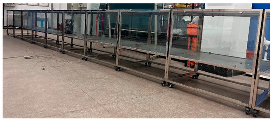
Figure 2.
Model drawing of tunnel scaling.
The material of the ignition source was chosen to be ethanol, with the chemical formula C2H6O. Since C2H6O is a common fuel used in pool fire experiments and its combustion properties are generally more favorable, the results from these experiments are studied and analyzed with a high degree of objectivity. Therefore, C2H6O has been selected as the fire fuel for the model. In addition its material properties are shown in Table 2.

Table 2.
Combustible properties.
The fire experiments were conducted for a total of 600 s, analyzing the changes in O2 and CO2 concentrations to determine the peak time of heat release rate. The materials and quality of the combustible materials used were consistent, and since the two fire sources are parallel combustion mechanisms, the changes in the concentration of each gas were plotted as shown in Figure 3. The y-axis of the graph shows the percentage of gases in the regional air.
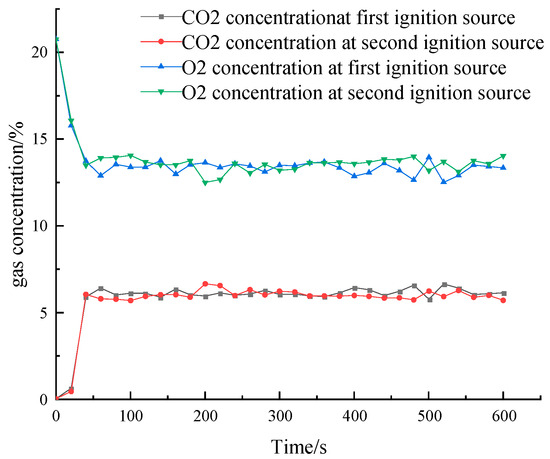
Figure 3.
Plot of CO2 and O2 concentration.
The figure illustrates that around 40 s, the CO2 concentration peaks for the first time while the O2 concentration reaches its lowest point, signaling the fire has entered the stable combustion stage. This is accompanied by the maximum rate of heat release. The flame height under standard conditions is determined by observing and measuring the flame height at 40 s. The calculation of heat release rate is shown in Equation (1).
where L is the flame height, m; D is the equivalent diameter of the fire source, m; Q is the heat release rate of the fire source, kW. Through the calculation, the equivalent diameter of the fire source is about 0.17 m. The height of the flame front is approximately 0.44 m. From the Equation (1) that can be obtained, the heat release rate of a single fire source is about 10.9 kW. The fire source to reach the peak of the heat release rate of the experimental model is shown in Figure 4.
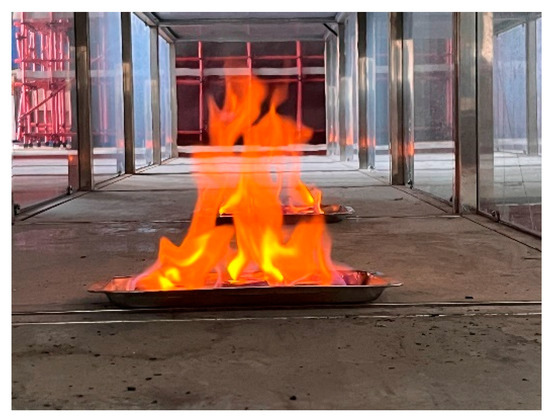
Figure 4.
Modeled peak rate of heat release from a single fire source.
2.2. Numerical Simulation Experimental Modeling
To ensure the accuracy of the numerical simulation, Pyrosim 2022 was utilized to create a model of equal scale to the experimental scaled-down model. Table 3 displays the pertinent parameters of the numerical simulation model.

Table 3.
Numerical simulation software boundary conditions.
After performing the experiment, the temperature at each of its 40 s detection points was compared, and its comparison graph is shown in Figure 5.
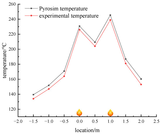
Figure 5.
Temperature comparison between simulation and experiment at 40 s.
The temperature peaks above the two fire sources at 40 s, with a lower temperature observed in the middle section between the sources. A comparison between experimental and numerical simulation temperatures shows a slight discrepancy, attributed to heat exchange differences between the experimental model and the numerical simulation. The experimental model features heat exchange with the environment, while the numerical simulation assumes adiabatic walls. Despite the lower experimental temperatures, the temperature distribution remains consistent. The maximum error observed is approximately 2.7%, indicating high accuracy in the numerical simulation results.
3. Analysis of Experimental Results
3.1. Research on the Change Rule of Temperature Change of Double Fire Source
When the fire plume impacts the roof, it generates a jet along the roof and simultaneously releases high-temperature smoke into the surrounding area. The temperature distribution of the fire smoke within the tunnel significantly influences the diffusion and settling of the smoke. Therefore, studying the temperature distribution on the roof is crucial for understanding the mechanisms of fire catastrophes [25].
At 40 s, the temperature rise change of each measurement point is examined. It is observed that the temperature decay change of both double fire sources and single fire sources is essentially the same. Furthermore, all of them closely adhere to the exponential decay law. The roof temperature decay model is shown in Equation (2) [26].
where: is the dimensionless average temperature rise; x − x0 is the horizontal distance from the reference point to the fire source, m; k is the straight tunnel attenuation coefficient, the calculation of which is given in Equation (3) [26].
where: α is the combined heat transfer coefficient of the flue gas layer, W/(m2·K); m is the mass flow rate of the fire smoke stream, kg/s; D is the length of the smoke layer in contact with the wall of the tunnel, m. Due to the fact that in the actual experiments, the smoke generation rate is low and does not contact the ground, the expression of the heat transfer coefficient is Equation (4) [26].
where: hc is the convective heat transfer coefficient in W/(m2·K); hr is the radiative heat transfer coefficient in W/(m2·K); and B is the length of the cross-section of the flue gas layer in the part that does not come into contact with the tunnel wall in m. The formula for hc and hr is given in Equation (5) [26].
where: K′ is the empirical relationship constant, taken as 8.7 kCal/m2°C; u is the horizontal propagation velocity of the flue gas, m/s. ε is the emissivity; σ is Boltzmann’s constant, 5.67 × 10⁻¹¹ kW/(m2·K4); Ts is the temperature of the smoke stream, K; Tsur is the temperature of the wall surface and is generally the ambient temperature., K.
Combining the above equations, the total heat transfer coefficient of the smoke flow from a curved tunnel fire can be obtained; see Equation (6).
Bringing Equations (6) and (3) into Equation (2) leads to Equation (7).
As the combustion process becomes more complete, the amount of smoke produced decreases. This results in a smoke horizontal propagation speed that is comparable to a secondary source of fire influenced by wind speed. Experimental measurements indicate a wind speed of approximately 2.3 m/s, leading to an attenuation coefficient of about 0.0049. Its calculation flowchart is shown in Figure 6.
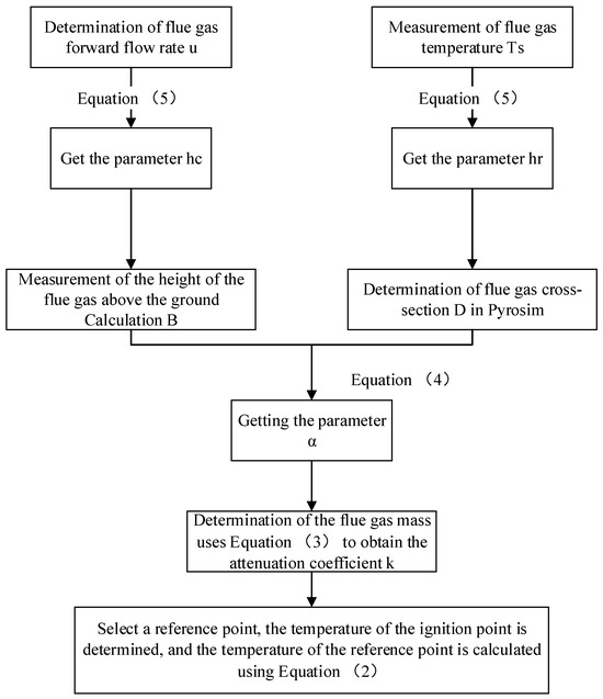
Figure 6.
Computational flow chart.
In Figure 6, the formulas indicated therein are all numbered as formulas in the text. By incorporating this value of k into the formula, the temperature change curve can be obtained, as depicted in Figure 7.
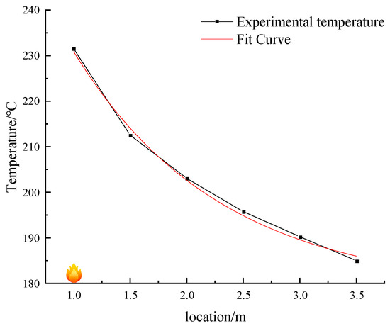
Figure 7.
Experimental temperature drop curves and equation fitting curves.
According to the data presented in Figure 4, the fitting ratio between the curve generated by the formula and the actual values can reach 0.98, indicating a strong level of fit. This suggests that the attenuation pattern of the dual-source fire downstream of the fire source is largely in line with that of a single-source fire.
3.2. Study of the Phenomenon of Dual Source Fires
Through experiments and numerical simulations, it has been observed that the average temperature in the tunnel is significantly higher during a double fire source incident compared to a single fire source incident. Additionally, the temperature near the ground between the double fire sources exhibits a ‘concave’ distribution pattern. The vertical temperature distribution is illustrated in Figure 8.

Figure 8.
Vertical temperature cloud.
T The temperature distribution pattern observed in Figure 5 shows that temperatures are higher near the ground close to the fire source and decrease rapidly after a certain horizontal distance from the source. The temperature between the two fire sources in the tunnel is higher, primarily due to the thermal resistance of the fire sources causing a buildup of high-temperature smoke. This results in a distinct demarcation line between the upper portion of the high-temperature smoke near the walls and the lower portion where heat exchange occurs with the environment. The vertical height is lower in this region due to the heat exchange, creating a clear boundary. Additionally, the air convective effect from the fire plume on both sides causes the high-temperature smoke to flow towards each other, leading to noticeable differences in temperature and flame shape. These experimental findings are illustrated in the changing trend of the flame front, as depicted in Figure 9.

Figure 9.
Schematic diagram of flame front tilt.
Due to the unique characteristics of its fire field, a dual source of fire has a greater potential to generate and accumulate temperature and smoke compared to a single source of fire. In order to analyze the characteristics of a dual source of fire in a real tunnel, this study examines the impact of varying fire spacing and ventilation conditions on fire behavior. Numerical simulation software is used to model a full-scale tunnel with a dual source of fire.
4. Numerical Simulation and Analysis of Double-Source Fire in Full-Size Tunnel
4.1. Establishment of Full-Size Tunnel Model
During a visit to a mining enterprise in Shanxi Province, a scaled-down model of a tunnel section measuring 4 m × 3 m was established. The model was created based on the principles of power similarity and motion similarity in hydrodynamics, ensuring that it was isometrically scaled with the actual mode. The scaling relationship can be described by Equation (8):
where λ is the scaling relationship between the scaled model and the full-size model, l is the feature length, m. m is the scaled model corner scale, and p is the full-size model corner scale.
A scaled model with a geometrically similar scale relationship of about 7.2 is utilized for fire experiments. A tunnel model measuring 300 m in length, 4 m in width, and 3 m in height was created using Pyrosim. A smoke exhaust tunnel measuring 4 m in width and 3 m in height was established at 250 m along the tunnel. An ignition source was placed at 110 m from the air inlet of the tunnel, with a surface area of 1 m2. The upwind fire source served as the reference source. Another ignition source was placed at a distance ‘D’ from the first source. Temperature sensors were strategically placed at the top of the tunnel and at a height of 1.6 m to monitor various fire characteristics during fire incidents. These sensors were spaced 5 m apart, with the first sensor positioned at the center of the reference fire source. Additionally, six sensors of the same type were placed on the upwind side at the same vertical height, followed by 19 sensors downstream of the fire and 26 sensors at the same vertical height. Refer to Figure 10 for the lane model diagram.
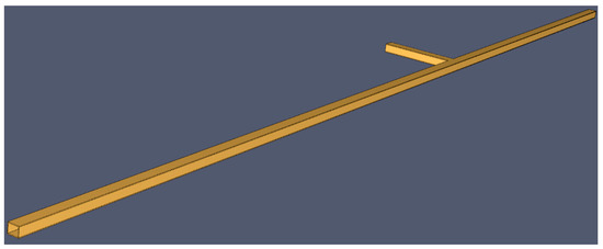
Figure 10.
Horizontal section of the tunnel.
4.2. Mesh Irrelevance Test
It has been shown that the simulation accuracy of Pyrosim is higher when the mesh size is 1/16 to 1/4 times the diameter of the surface of the fire source. Its calculation, Equation (9) [27], is:
where D* is the characteristic diameter of the fire source, m; ρ0 is the ambient air density, taking the value of 1.293 kg/m3; cp is the specific heat capacity of air, taking the value of 1.005 KJ/(kg·K); T0 is the temperature, taking the value of 293 K.
The sparsity of the grid not only significantly affects the accuracy of the simulation but also influences the computational runtime. The Pyrosim manual suggests that the value of D*/x should be maintained between 4 and 16 to achieve higher calculation accuracy. According to the Formula (9), D* is calculated to be 2.627 m, indicating that a grid size between 0.16 m and 0.65 m yields optimal accuracy. To verify this, grid sizes of 0.1 m, 0.25 m, 0.35 m, and 0.5 m were tested under windless conditions, with a fire source spacing of 15 m, focusing on the midpoint temperature of the double fire source to assess grid independence.
As illustrated in Figure 11, when the grid sizes are set to 0.1 m, 0.25 m, and 0.35 m, the results demonstrate a high degree of fit. Considering the computational time, a grid size of 0.1 m × 0.1 m was selected for areas near the fire source, while a grid size of 0.25 m × 0.25 m was chosen for the other tunnel areas. In total, four mesh regions were established, encompassing 1,984,256 mesh. Additionally, the parallel computing mode of Pyrosim is employed, significantly reducing the overall computation time.
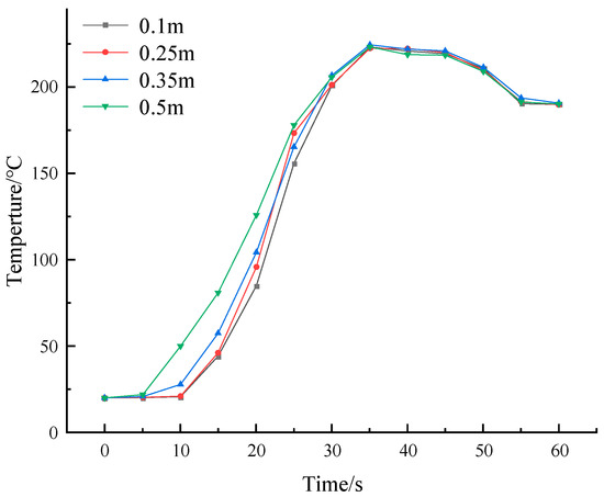
Figure 11.
Mesh independence test.
4.3. Fire Source and Other Boundary Conditions
To better understand real fire combustion scenarios, the t2 fire model was chosen, with its single source combustion model represented by Q for fire heat release rate in kW/m2, a for fire growth factor, and t for the time taken for the fire to reach its peak heat release rate in seconds. The study focuses on the parallel combustion mechanism of two fire sources to analyze the impact of varying heat release rates on fire temperature and smoke spread patterns. The fire growth factor is determined as a = 0.02314 kW/s2, with a simulation time of 800 s. Other measuring devices are shown in Table 4.

Table 4.
Device measurement settings.
4.4. Determination of Critical Wind Speed for Twin Source Fires
The critical wind speed problem for the nine conditions and the single fire source was initially determined by simulating the nine conditions. Its simulation flowchart is shown in Figure 12.
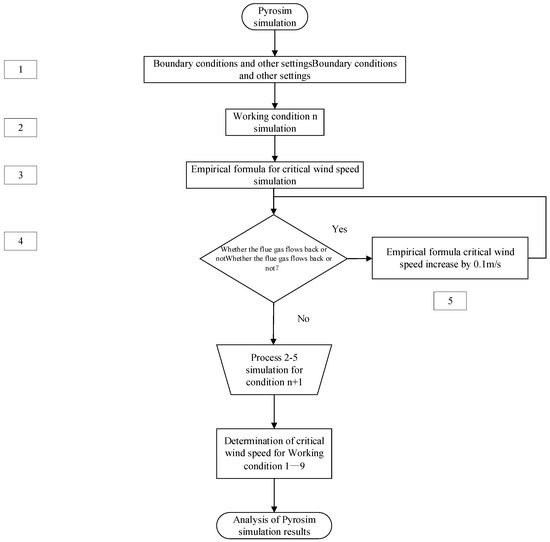
Figure 12.
Pyrosim simulation flowchart.
The criterion for determining the critical wind speed for a two-fire source fire was based on ensuring that the backflow of smoke and temperature did not exceed that of the upstream fire source. The critical wind speed of a single fire source for this tunnel condition was calculated using Wu and Bakar’s critical wind speed prediction model. It is modeled as in Equation (10) [27].
In the formula, Q* for the dimensionless heat release rate; Q for the heat release rate of the fire source, kW; ρ0 for the air density, kg/m3; T0 for the ambient temperature of the air, K; g for the acceleration of gravity, m/s2; H for the hydraulic diameter, m. The expression of the hydraulic diameter is: H = 4S/P, S for the cross-sectional area of the tunnel, m2, and P for the perimeter of the tunnel cross-section, m. The hydraulic diameter of the tunnel cross-section of the tunnel cross-section of the perimeter of the tunnel cross-section of the tunnel cross-section, m.
Baker calculates the dimensionless wind speed by taking the heat release rate from the fire source, and its prediction model for the dimensionless wind speed is Equation (11) [27].
By calculating the dimensionless wind speed, the critical wind speed can be calculated using the critical wind speed prediction model, which is shown in Equation (12) [28]:
where v is the critical wind speed, m/s, which is approximately 1.76 m/s as determined by an empirical formula.
Taking into account various factors such as section and wall characteristics, a wind speed of 1.7 m/s is chosen as the central value, with incremental and decremental variations of 0.1 m/s for ten simulations on either side. Through simulation studies, it was observed that the critical wind speed for a single fire source is 1.8 m/s. Table 5 presents the critical wind speeds under different conditions.

Table 5.
Critical wind speed for each operating condition.
The critical wind speed calculated is 1.68 m/s, whereas the critical wind speed in the simulation is 1.8 m/s. This discrepancy can be attributed to the fact that the prediction of the critical wind speed does not consider the wall friction of the tunnel, resulting in a slight deviation between the modeling and simulation outcomes. Some scholars have investigated the impact of using a large nest model on the critical wind speed in numerical simulations of turbulence models. They found that the critical wind speed for a double fire source is slightly higher than that for a single fire source. The primary reason for this is that dual-source fires exhibit higher thermal resistance compared to single-source fires, which in turn increases the local ventilation resistance within the fire zone. Consequently, this necessitates higher critical air velocities. Analysis of nine different conditions revealed a negative correlation between the critical wind speed for a double fire source and the distance between the fire sources. Specifically, the greater the distance between the fire sources, the lower the required critical wind speed. At the same time, when the distance between fire sources reaches 20 m, its critical wind speed is close to the critical wind speed of a single fire source. This phenomenon can primarily be attributed to the increased distance between fire sources, which has weakened the local thermal resistance. Additionally, the heating of the upstream fire source affects the downwind side, leading to a reduction in fluid density. As the temperature rises, a certain amount of energy is acquired, resulting in an increased flow rate downstream of the upstream fire source. Consequently, for fire sources that are significantly spaced apart, the critical wind speed required for fire propagation will be lower compared to that of fire sources that are positioned closer together.
The simulation revealed that when the power of two fire sources in a tunnel is equal, the fire characteristics align closely with scaled model experiments. The horizontal temperature distribution in the tunnel resembles a ‘concave’ shape after the fire under these conditions. However, the influence of wind speed on the two fire sources differs, with the upstream source being more affected. This results in a lower peak temperature for the upstream source compared to the downstream source, due to the thermal resistance effect cutting the wind speed impact on the downstream fire source. The thermal resistance effect of the upstream fire source mitigates the wind speed influence on the downstream fire source temperature, leading to a lower temperature peak for the upstream source. The temperature rise between the two fire sources is primarily driven by the fire plumes of both sources. As high-temperature smoke accumulates between the two sources, the thermal resistance effect of both sources limits smoke propagation, creating an anti-buoyancy wall jet. The vertical temperature rise between the two fire sources relies on convective heat transfer, while the high-temperature smoke on the roof of the sources exchanges heat with the surroundings, causing the middle region’s temperature to rise from top to bottom. The vertical temperature gradient in this middle area becomes more pronounced as the temperature decreases from top to bottom.
Simulation experiments were conducted under four identical dual-fire source conditions 1, 4, and 7, where wind velocity surpassed the critical threshold. The study focused on analyzing temperature field variations at a vertical height of 1.6 m, corresponding to the characteristic height of the human eye. The findings are illustrated in Figure 13, Figure 14 and Figure 15.
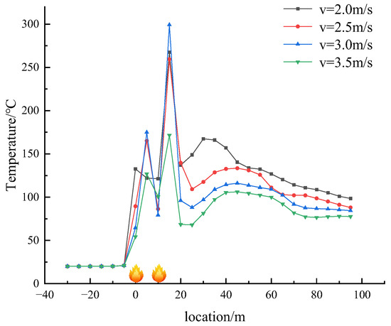
Figure 13.
The temperature of the tunnel varies at different wind speeds in working condition 1.
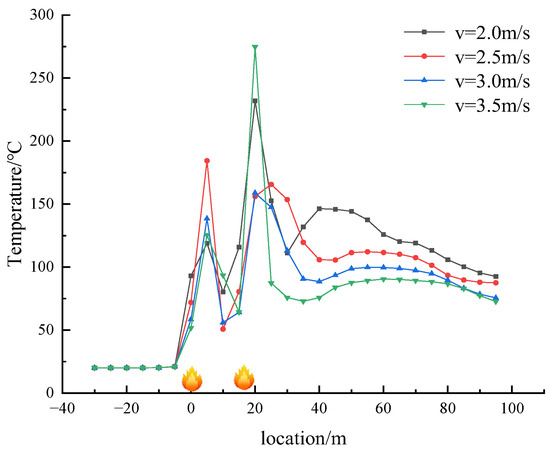
Figure 14.
The temperature of the tunnel varies at different wind speeds in working condition 4.
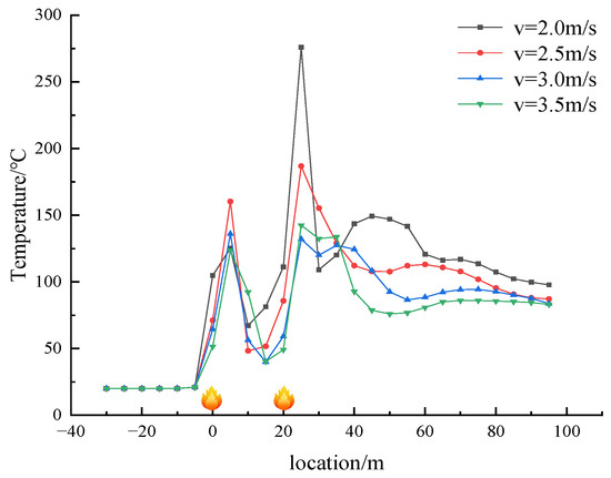
Figure 15.
The temperature of the tunnel varies at different wind speeds in working condition 7.
The analysis of Figure 13, Figure 14 and Figure 15 indicates that all three scenarios follow the same temperature decay pattern, with temperature decreasing as wind speed increases. However, when considering fires at different distances from each other but with the same heat release rate and wind speed, it is observed that greater spacing between fires leads to higher average temperatures along the tunnel due to the temperature differences between the fires. Specifically, temperatures between closely spaced fires are significantly higher than those downstream, with temperatures evening out at points after the downstream fire source. Regardless of wind speed, the temperature distribution between the fire sources maintains a ‘concave’ shape, with the lowest temperature occurring at the midpoint between the two fires.
The influence of wind speed on the maximum temperature within the tunnel is more pronounced, particularly regarding the upstream fire source in comparison to the downstream fire source. This phenomenon can be attributed to the fact that as wind speed increases, the thermal resistance effect of the upstream fire source on the wind flow diminishes, while the cooling effect of the wind flow on the downstream fire source intensifies. At a wind speed of 3.5 m/s, the temperatures above both sources are nearly identical, indicating a negative correlation between the maximum temperature and wind speed.
4.5. Fire Characterization of Different Ignition Powers
By simulating equal fire growth factors under different fire powers in a two-ignition fire, a developmental relationship between the two ignition sources was observed. Specifically, when one ignition source develops rapidly, it suppresses the development of the other ignition source. This relationship is illustrated in the temperature cloud shown in Figure 16.

Figure 16.
Temperature cloud of working condition 1 (top) and working condition 2 (bottom).
Under critical wind speed conditions, the power of the upstream fire source remains constant while the downstream fire source has a power of 4 MW, resulting in a more intense flame compared to the 3 MW source. However, the combustion of the upstream fire source is relatively suppressed, leading to a noticeable decrease in temperature and flame height. This phenomenon occurs due to the rapid influx of fresh air towards the downstream fire source, causing a reduction in oxygen available for the upstream source. As a result, the combustion of the upstream source is hindered, leading to a decrease in flame height and a change in temperature. This relationship is illustrated in Figure 17.
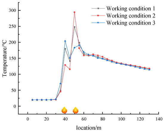
Figure 17.
Temperature variation of working conditions 1, 2, and 3.
As illustrated in Figure 18, working condition 3 exhibits the lowest average temperature. However, the temperature above its upstream fire source is the highest due to the relatively high heat release rate. Despite having the same power as the downstream fire source in working condition 1, the downstream fire source in working condition 3 is inhibited by the upstream fire source, resulting in a significantly lower temperature compared to working condition 1. The temperature difference between the two cases is approximately 70 °C.
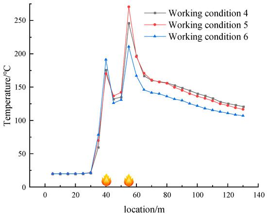
Figure 18.
Schematic diagram of temperatures for conditions 4, 5, and 6.
For the other two types of conditions, a consistent regularity is maintained, and the temperature schematics for conditions 4, 5, 6, 7, 8, and 9 are shown in Figure 18 and Figure 19.
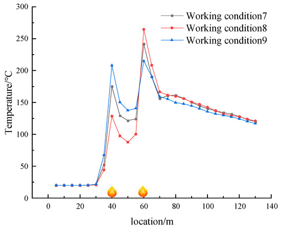
Figure 19.
Schematic diagram of working conditions 7, 8, and 9 temperatures.
Comparison of the three working conditions reveals that the upstream fire source power is larger when the average temperature and temperature peak in the starting tunnel are lower. On the other hand, the downstream fire source power is larger when the average temperature and temperature peak are higher. Therefore, in cases of dual fire sources, it is crucial to focus on treating the fire source on the downwind side. When the wind speed is greater than the critical wind speed, the fire source upstream is less affected by the escape environment. Conversely, the fire source power on the downwind side has a more significant impact on the escape route. It is essential to optimize firefighting strategies based on this pattern.
5. Conclusions
(1) The temperature of the dual-ignition source fire resulting from the ‘jumping’ discontinuous fire spread on the tunnel exceeds that of a single-ignition source fire. We conducted a scaled-down model experiment of the dual-ignition source fire, along with a numerical simulation of the same model. Our analysis determined that the experimental model took approximately 40 s to reach the maximum rate of heat release from the ignition source, with a power output of 10.9 kW. Additionally, the numerical simulation and the scaled-down model were validated, demonstrating a maximum error in results of no more than 2.7%. This validation confirms the high accuracy of the numerical simulation in representing the dual fire source scenario within the tunnel.
(2) The study investigated the temperature decay law of the roof temperature in relation to the distance from the double fire source. It was observed that the roof temperature decay law closely resembled that of a single fire source, exhibiting exponential decay. The decay coefficient was calculated to be 0.0049 using the temperature decay formula, with a high fitting degree of 0.98 between the formula and actual values.
(3) Numerical simulation software was utilized to simulate nine distinct working conditions at the same location, each with varying fire source power. The study revealed a competitive relationship between the two fire sources, indicating that an increase in power of one fire source leads to the inhibition of combustion in the other. Additionally, an analysis of temperature distribution revealed that when the power of the upstream fire source increases, the downstream fire source is inhibited to a greater extent. This leads to the lowest average temperature within the tunnel, with the temperature peak also being the lowest.
(4) An emergency rescue program can be developed based on the fire characteristics of dual ignition sources. Downstream ignition sources have the most significant impact on the escape environment on the downwind side of the tunnel. Therefore, water spray should be directed towards the middle of the bottom rollers of the tape, the tail, and other flammable points near the tail of the tunnel to suppress the downstream ignition sources and create favorable conditions for the evacuation of personnel.
Author Contributions
X.Z. was responsible for the numerical simulation and theoretical analysis part; M.N. is responsible for numerical simulations, experiments, data logging analysis, and paper writing; W.W. is responsible for data checking and validation; H.W. and J.W. were responsible for the collation of articles and correction of errors. All authors have read and agreed to the published version of the manuscript.
Funding
This study was supported by General Program of the National Natural Science Foundation of China (Grant No. 52064043) and General Program of the National Natural Science Foundation of China (Grant No. 51764044).
Institutional Review Board Statement
Not applicable.
Informed Consent Statement
Not applicable.
Data Availability Statement
Data and other information can be obtained by contacting e-mail address 220857002156@sxdtdx.edu.cn.
Conflicts of Interest
The authors declare no conflicts of interest.
Nomenclature
| physical quantity | marginal notes |
| Relative ambient temperature rise of high-temperature smoke at distance x from the fire source, °C | |
| Ambient temperature rise at fire source location, °C | |
| k | Temperature decay coefficient |
| x | Reference position from the source of the fire, m |
| x0 | fire source distance, m |
| α | Combined heat transfer coefficient of the flue gas layer, W/(m2·K) |
| D | the length of the smoke layer in contact with the wall of the tunnel, m |
| cp | constant-pressure specific heat, KJ/(kg·K) |
| m | the mass flow rate of the fire smoke stream, kg/s |
| hc | the convective heat transfer coefficient, W/(m2·K) |
| hr | the radiative heat transfer coefficient in W/(m2·K) |
| B | the length of the cross-section of the flue gas layer in the part that does not come into contact with the tunnel wall, m. |
| u | the horizontal propagation velocity of the flue gas, m/s. |
| K′ | the empirical relationship constant, kCal/m2°C |
| ε | the emissivity |
| σ | Boltzmann’s constant |
| Ts | the temperature of the smoke stream, K |
| Tsur | the temperature of the wall surface, Kc |
| s | Cross-sectional area of the flue gas layer, m2 |
| ρ | Ambient air density, kg/m3 |
| Q* | the dimensionless heat release rate |
| Q | the heat release rate of the fire source, kW, °C |
| ρ0 | the air density, kg/m3 |
| T0 | the ambient temperature of the air, K |
| g | the acceleration of gravity, m/s2; |
| H | the hydraulic diameter, m |
| v* | Dimensionless wind speed |
| v | critical wind speed |
References
- Yue, N.; Cai, G.; Gao, W.; Quan, Y.; Wang, F. Research on influencing factors of water mist suppression for belt spreading fire in mine. J. Saf. Sci. Technol. 2022, 18, 92–97. [Google Scholar]
- Ji, J.W.; Cheng, Y.P. Fire Dynamics; China University of Mining and Technology Press: Xuzhou, China, 2018. [Google Scholar]
- Hu, L.H.; Peng, W.; Yang, R.X. Fundamentals of Tunnel Fire Dynamics and Prevention Technology; Science Press: Beijing, China, 2014. [Google Scholar]
- Fukuda, Y.; Kamikawa, D.; Hasemi, Y.; Kagiya, K. Flame Characteristics of group fires. Fire Sci. Technol. 2004, 23, 164–169. [Google Scholar] [CrossRef]
- Liu, N.; Liu, Q.; Lozano, J.S.; Shu, L.; Zhang, L.; Zhu, J.; Deng, Z.; Satoh, K. Global burning rate of square fire arrays: Experimental correlation and interpretation. Proc. Combust. Inst. 2009, 32, 2519–2526. [Google Scholar] [CrossRef]
- Yu, M.; Su, G.; Chen, J. Numerical studies on the effect of double fire sources upon critical ventilation velocity in tunnel fires. Fire Saf. Sci. 2017, 26, 20–28. [Google Scholar]
- Liu, Q.; Zheng, F. Study on Variation Rules of Critical Ventilation Velocity for Double-source Tunnel Fires. J. Disaster Prev. Mitig. Eng. 2018, 38, 137–143. [Google Scholar]
- Cui, X.; Zhao, J.; Yao, R.; Yuan, S.; Wu, B.; Huang, H. Numerical simulation on double fire source tunnel. J. Cent. South Univ. (Sci. Technol.) 2022, 53, 2255–2267. [Google Scholar]
- Tsai, K.C.; Chen, H.H.; Lee, S.K. Cortical ventilation velocity for multi-source tunnel fires. J. Wind. Eng. Ind. Aerodyn. 2010, 98, 650–660. [Google Scholar] [CrossRef]
- Guo, C.; Yan, Z.; Li, W.; Zhou, X. A Full-scale Experimental Study on the Fire Characteristics of Dual-source Tunnel Fire. Mod. Tunn. Technol. 2023, 60, 247–259. [Google Scholar]
- Xu, H.; Zhao, W.; Lv, S. Experimental Study on the Combustion Characteristics of two Fire Sources in a Tunnel. J. Eng. Thermophys. 2020, 41, 1254–1260. [Google Scholar]
- Zhong, M.; Shi, C.; He, L.; Shi, J.; Liu, C.; Tian, X. Smoke development in full-scale sloped long and large curved tunnel fires under natural ventilation. Appl. Therm. Eng. 2016, 108, 857–865. [Google Scholar] [CrossRef]
- Yao, Y.; Cheng, X.; Shi, L.; Zhang, S.; He, K.; Peng, M.; Zhang, H. Experimental study on the effects of initial sealing time on fire behaviors in channel fires. Int. J. Therm. Sci. 2018, 125, 273–282. [Google Scholar] [CrossRef]
- Ji, J.; Wan, W.; Gao, Z.; Fu, Y.; Sun, J.; Zhang, Y.; Li, K.; Hostikka, S. Experimental study on flame merging behaviors from two pool fires along the longitudinal centerline of model tunnel with natural ventilation. Combust. Flame 2016, 173, 307–318. [Google Scholar] [CrossRef]
- Molkens, T. FDS Versus En-Models. A Comparison between the Heskestad Model from EN and CFD Results. J. Struct. Fire Eng. 2015, 6, 3. [Google Scholar] [CrossRef]
- Qinghua, G.; Zhen, Y.L.; Haukur, I.; Yan, Z.; Zhu, H. Numerical study on thermally driven smoke flow characteristics in long tunnels under natural ventilation. Int. J. Therm. Sci. 2023, 192, 108379. [Google Scholar]
- Liu, N.A.; Zhang, S.J.; Luo, X.S.; Lei, J.; Chen, H.; Xie, X.; Zhang, L.; Tu, R. Interaction of two parallel rectangular fires. Proc. Combust. Inst. 2019, 37, 3833–3841. [Google Scholar] [CrossRef]
- Haukur, I.; Ying, Z. Model scale tunnel fire tests with longitudinal ventilation. Fire Saf. J. 2010, 45, 371–384. [Google Scholar]
- Oerkan, K. An Experimental study on the effects of blockage ratio and ventilation velocity on the heat release rate of tunnel fires. J. Fire Sci. 2011, 29, 555–575. [Google Scholar]
- Wan, H.; Gao, Z.; Ji, J.; Fang, J.; Zhang, Y. Experimental study on horizontal gas temperature distribution of two propane diffusion flames impinging on an unconfined ceiling. Int. J. Therm. Sci. 2019, 136, 1–8. [Google Scholar] [CrossRef]
- Wang, Q.; Wang, S.; Liu, H.; Shen, J.; Shang, F.; Shi, C.; Tang, F. Characterization of ceiling smoke temperature profile and maximum temperature rise induced by double fires in a natural ventilation tunnel. Tunn. Undergr. Space Technol. Technol. 2020, 96, 103233. [Google Scholar] [CrossRef]
- Zhang, Y.; Xing, S.; Chen, R.; Chen, L.; Li, T.; Mao, P. Experimental study on maximum temperature beneath tunnel ceiling under the condition of double fire sources. Tunn. Undergr. Space Technol. Technol. 2020, 106, 103624. [Google Scholar] [CrossRef]
- Chin, D.; Joaquim, P. Analysis of Fire Throttling in Longitudinally Ventilated Tunnels with a One-dimensional Model. Fire Technol. 2022, 58, 2925–2947. [Google Scholar]
- Song, Y.; Jiang, H. Pyrosim-based Simulation of Differentiated Sprinkler System for Terminal Fire. Sci. Technol. Eng. 2021, 21, 10998–11004. [Google Scholar]
- Hu, L.H.; Huo, R.; Li, Y.Z.; Wang, H.B.; Chow, W.K. Full-scale burning tests on studying smoke temperature and velocity along a corridor. Tunneling Undergr. Space Technol. 2005, 20, 223–229. [Google Scholar] [CrossRef]
- Hu, L.H. Studies on Thermal Physics of Smoke Movement in Tunnel Fires. Ph.D. Thesis, University of Science and Technology of China, Hefei, China, 2006. [Google Scholar]
- Zhao, X.K.; Ni, M.H. Research on fire characteristics of different curvature curved tunnels based on PyroSim. Fire Sci. Technol. 2024, 43, 309–313. [Google Scholar]
- Wu, Y.; Baker, M.Z.A. Control of smoke flow in tunnel fires using longitudinal ventilation systems—a study of the critical velocity. Fire Saf. J. 2000, 35, 363–390. [Google Scholar] [CrossRef]
Disclaimer/Publisher’s Note: The statements, opinions and data contained in all publications are solely those of the individual author(s) and contributor(s) and not of MDPI and/or the editor(s). MDPI and/or the editor(s) disclaim responsibility for any injury to people or property resulting from any ideas, methods, instructions or products referred to in the content. |
© 2024 by the authors. Licensee MDPI, Basel, Switzerland. This article is an open access article distributed under the terms and conditions of the Creative Commons Attribution (CC BY) license (https://creativecommons.org/licenses/by/4.0/).