Abstract
This study investigates the feasibility of using a composite material comprising slate reinforced with cork sheets for architectural purposes like facades and wall coverings. The research involves the comprehensive characterisation of both slate and cork materials along with the evaluation of the silicone adhesive used in their bonding process, specifically Sikasil® HT from SIKA®. It was found that both slate and cork exhibited low wettability, which was enhanced through cold plasma treatment. Subsequently, a composite sandwich structure was fabricated and subjected to impact testing in a drop tower, along with fire resistance evaluations. The fire tests revealed that when subjected to a flame of 900 °C for 15 min, the slate alone heated rapidly, reaching 500 °C within 3 min on the side opposite to the flame. However, the sandwich structure reached 260 °C on the cork side (opposite to the flame) at 7.5 min, maintaining this temperature until the deterioration or detachment of the cork between 11 and 12 min. This provided insulation and delayed ignition. The sandwich structure maintained its fire resistance due to the insulating properties of cork and the superior thermal resistance of silicone compared to other adhesives up to 260 °C. Overall, the results suggest the potential suitability of this sandwich structure for architectural applications. Its favourable adhesion properties and acceptable fire resistance indicate that it could serve as a viable alternative for construction materials in architectural contexts.
1. Introduction
The construction sector consumes a significant amount of energy (40% of energy consumption in the EU) and contributes greatly to CO2 emissions (36% of emissions in the EU) [1]. The use of new isolating materials of natural and/or renewable origin can greatly reduce this impact by two different pathways. Firstly, given the climate change situation, heat insulation systems can lead to substantial energy savings and a significant reduction in greenhouse gas emissions. On the other hand, the use of natural or reused materials leads to a reduction in solid wastes.
Slate is a metamorphic rock formed from the sedimentation of very fine-grained clays and silts (less than 75 μm), typically bluish-black or greyish in colour, with a high density (porosity less than 1%). Its mechanical behaviour is highly anisotropic, characterised by fissility due to its lamellar structure. The deformability and strength of slate rocks depend on the orientations of their planar structures relative to the applied stresses [2,3]. Extensive research has been conducted on the fracture of slate and its simulation, driven by the need to ensure its resilience in various structural or decorative applications [4,5,6,7,8]. In these studies, it has been consistently concluded that slate fractures invariably occur between the layers regardless of the direction of the external stresses. Its impermeability and the ease of splitting slate into thin plates (1.5 to 4 mm) enable its utilisation in various applications, such as tiles, cladding, and flooring (ranging from 4 to 9 mm). To achieve this, slate must be cut to appropriate sizes and perforated for fastening. However, traditional methods of processing often result in significant waste due to mechanical stresses causing fractures in the slate sheets. This waste material can be repurposed as additives in geopolymers [9] or as polymer reinforcements [10].
Since the Roman Empire, slate has been utilised across Europe in the production of tiles for waterproof coatings on roofs and walls. Coatings constitute one of the earliest well-established industries [11]. The behaviour of slate when subjected to low-energy impacts, such as hail, is similar to that of laminated panels. This typically results in face sheet–core debonding and is commonly referred to as barely visible impact damage, which can be challenging to identify [12].
Hailstorms often result in significant damage to both slate roofs and facades due to the material’s inherent fragility. While various factors may contribute to slate fracture, hail impacts are the primary cause. Studies have investigated the impact of free-falling objects on different materials using steel and ice balls of varying sizes and speeds [13,14,15]. When slate is struck, the upper layer can fracture, generating a compression wave that propagates through the layers to the end of the piece. Without any means to absorb this energy, the wave rebounds as a tensile wave, causing layer separation and the subsequent breakage of the slate piece. However, if the slate possesses an elastic backing that is capable of absorbing energy, the tensile wave either diminishes or is eliminated altogether, preventing the slate from breaking.
A slate intended for roofing must adhere to various construction requirements outlined in different standards for roofing slate. These include weather resistance, good mechanical properties, and waterproofing due to its low porosity [16]. Similarly, slate used for facades must exhibit sufficient mechanical strength to withstand minor impacts. However, moisture present in the environment can penetrate between the layers of slate through capillary action [17]. An increase in relative humidity from 55% to 92% reduces its mechanical strength to one-third [17]. Experimental tests studying the effects of low temperatures in a semi-polar climate show a 24% decrease in mechanical strength due to cracking caused by ice intrusion between slate layers [18].
The impact of heat from a fire on slate has a dual effect: (i) it causes alteration in colour due to changes in chemical composition and (ii) a decrease in mechanical strength [19,20]. A Differential Thermal Analysis (DTA) and Thermogravimetric Analysis (TG) reveal two critical temperatures to be 640 °C and 725 °C, corresponding to the disappearance of OH groups from chlorite and a mass loss of 7.15%, respectively.
From a fire safety perspective, slate holds an A1 rating (indicating non-combustibility) according to EN 12326:2015 [21]. Its thermal conductivity is 2.2 W/mK perpendicular to the plates and is twice that along the longitudinal axis due to the lower cohesion between the layers [22]. Therefore, it can be used as an effective insulator.
The second material used in this work is cork. It is a renewable eco-material that is increasingly attracting interest due to its inherent characteristics. This material is sustainably extracted from the cork oak (Quercus suber L.). Eighty-five percent of the production of this material is concentrated in the Iberian Peninsula and Morocco, specifically in Portugal (Central zone, Alentejo, and Algarve) and Spain (Extremadura), with an estimated production of 201,428 tons per year from approximately 2,139,942 ha of cork forest [23]. It contains suberin (42–45%), lignin (22–27%), cellulose and polysaccharides (10–15%), tannic acid, wax, and other substances. Its closed-cell structure (80% of its volume is air) provides it with good qualities as a thermal and acoustic insulator, allows it to have reduced permeability to liquids and gases, and makes it chemically inert, and it has the ability to deform viscoelastically under external stresses [24,25] and a high resistance to compression loads [26]. Due to the flexibility of suberin, cell wall corrugations can act as folding pathways, allowing cell walls to bend and unfold under high stresses without damage [27,28].
Numerous studies evaluated the sustainability of cork by providing detailed assessments of the environmental impact of product life cycles, comparing cork products with the most common non-renewable materials applied in decorative solutions such as flooring [29,30], insulating materials [31,32], and wall coverings [33,34]. In addition, the cork sector is considered a net carbon sink when biogenic carbon is included since more carbon is sequestered than emitted along the sector [35]. For example, insulation materials such as insulation cork boards (ICBs) exhibit a negative carbon footprint, with that of ICBs being −116.229 kg CO2/m3. This is attributed to the use of renewable raw materials and biomass to provide steam in the manufacture process [36].
The main application of cork is in the stopper industry. In the manufacture of stoppers, only 20% of the initial cork is used [37], with the rest being waste. Some studies have been carried out using waste from the cork industry for its gasification [38] and use as fuel to obtain cork phenolic fraction compounds [39]. Cork particles agglomerated with alkali-activated materials have been studied as substitutes for Portland cement, as thermal and acoustic insulating materials [40] for lightweight mortars, or as additives in geopolymers [41]. Cork powder has been used as a filler for epoxy resins to increase their toughness under impact stress [42,43].
Cork agglomerates are produced by taking advantage of the large amount of residual by-products from the manufacture of cork stoppers and discs, as well as raw cork waste from planks and other types of pristine cork raw materials [21,44]. Cork particles between 0.5 and 2 mm in diameter can be used in the manufacture of agglomerate sheets by a hot-pressing process together with water-based binders (such as urea–formaldehyde, melamine, or phenolic adhesives), obtaining densities ranging from 200 to 280 kg/m3 and a Young’s modulus of 17.4 MPa [45]. Cork agglomerates show promise as shock absorption material. Furthermore, cork agglomerates are capable of withstanding higher impact forces than thermoplastic foams, such as EPS (expanded polystyrene), recovering their initial dimensions after impact and subsequently absorbing multiple impacts [46,47,48].
Regarding the reaction to fire, the classification of the cork panel is class E according to the Euroclass classification (EN 13501-1:2019) [49]. When cork is used as the core of the panelling, without being in direct contact with the flame, it is classified as M1 (combustible but not flammable) [50]. Therefore, it can dampen the flame and resist fire. Cork has been used as a thermal ablative in spacecraft since the 1970s [51]. Given the thermal conductivity of cork tile floors with a thickness between 3.2 and 8 mm, which is 0.037–0.045 W/mK, cork is a good thermal insulator [25]. Thermal conductivity increases with temperature; for ICBs, it rises from 0.020 W/mK at 20 °C to 0.054 W/mK at 80 °C, representing a 75% increase [52]. An increase in thermal conductivity may decrease the insulating properties of cork.
From the perspective of traditional building construction, various construction systems exist, all of which are complex and challenging to quantify in terms of cost and time. However, in the realm of industrialised construction, there is a preference for implementing standardised construction models. These models can reduce construction times and lower execution costs compared to traditional methods [53]. This preference for standardised construction often leads to the production of prefabricated and modular houses [54,55].
Prefabricated and modular houses typically require laminate panels for their construction. This study aims to investigate the feasibility of using slate reinforced with cork as an alternative building material for sustainable construction, particularly in the manufacture of laminate panels for facades or interior use in prefabricated and modular houses [56]. The production process involves thoroughly bonding the components—an elastic adhesive, slate, and cork—together to create the panels. Subsequently, mechanical testing is conducted to evaluate the structural integrity of the manufactured panels. Additionally, fire resistance testing is performed to assess their fire resistance properties.
In construction, understanding fire behaviour is crucial alongside controlling the mechanical strength. The proposed system aims to create slate–cork–slate panelling that is suitable for both indoor and outdoor use for walls, partitions, and even roofs. This system reinforces slate upon impact by providing it with elastic support, which absorbs a significant portion of the impact energy, especially at low speeds such as those encountered during hailstorms. To achieve this support, a cork sheet is bonded to the board using an elastic adhesive with high-temperature resistance. The primary objective of the work is to study the evolution of the sandwich structure when it is exposed to fire to evaluate its resistance. This type of structure has not been previously utilised in the habitat industry or any other industry, making it a novel area of exploration.
2. Materials and Methods
2.1. Materials
The studied slate comes from the Valdeorras area (Orense, Spain) and is formed by mica, chlorite, quartz, and feldspar [57]. Its density is 2.6 × 10³ kg/m3, and the slate thickness is 5.2 ± 0.8 mm. The slate was cut in pieces with a size of 80 mm × 80 mm for impact and fire tests.
The used cork agglomerate was provided in rolls 8 m long and 0.5 m wide with a thickness of 4 mm. Its thermal conductivity is 0.042 W/mK, with a density of 218 kg/m3 and fire classification of Euroclass D [49,58]. The cork roll is branded SDL and was supplied by Leroy Merlin (Madrid, Spain). Figure 1a shows how cork particles are bonded in the agglomerate with the binder, and Figure 1b shows how the cork structure is flattened in the bonding area. This flattening is due to the manufacturing process, where the particles with resin pass through a hot roller for resin compaction and curing. It was also cut into 80 mm × 80 mm pieces.
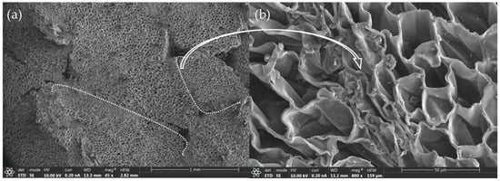
Figure 1.
(a) A micrograph of the cork agglomerate (45×); the white dotted lines mark the joints between two cork particles. (b) Details of the union between two particles (800×).
The silicone used was SikaSil® HT, supplied by Sika S.A.U. (Alcobendas, Spain). It corresponds to neutral silicone putty (oxime type), which is temperature-resistant and can work continuously up to 325 °C and occasionally at 350 °C. Its curing is carried out by ambient humidity, with roughly 2 mm of curing in 24 h at 23 °C and a 50% relative humidity (RH). Sikasil has a fire classification of M2 according to the standard EN 13501-1:2019 [49].
2.2. Slate and Cork Characterisation
2.2.1. Surface Treatment
The slate and cork samples were cleaned with methyl ethyl ketone (MEK) after being cut. The water contact angle on the cork yielded very low wettability values with a contact angle of 95° ± 5°. However, slate reported a contact angle of 45° ± 2°, which may be adequate, but previous adhesion tests with silicone showed low adhesion. Consequently, to enhance the sandwich structure, atmospheric pressure plasma treatments (APPTs) with a torch were conducted to improve wettability and enhance adhesion with the silicone adhesive.
An APPT device from Plasmatreat GmbH (Steinhagen, Germany) was utilised for treating the slate (Figure 2a) and cork laminate (Figure 2b). Employing potential-free thermodynamic equilibrium plasma treatments, also referred to as cold treatments, effectively cleansed and activated the predominantly polymer surface [59]. This equipment works at a frequency of 17 kHz and operates with a high-voltage discharge of 20 kV. It features a rotating torch with a ratio of 12.5 mm, culminating in a nozzle (1900 rpm) through which the plasma is discharged. The system includes a platform equipped with electronic speed control for accommodating the material being treated. Air plasma was generated within the rotating nozzle at a working pressure of 2 bar, utilising an off-balance discharge mechanism, and then expelled through a circular opening onto the samples. The distance between the sample and the plasma torch nozzle was maintained at 10 mm, while the speed of the platform was optimised at 20 mm/s. These parameters were optimised by checking the various conditions of the rate from 10 mm/s to 40 mm/s and the distance from 6 mm to 15 mm. The aim was to achieve the lowest contact angle with deionised water without causing damage to the surface.
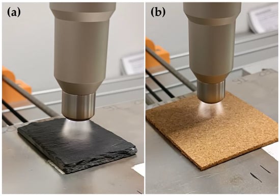
Figure 2.
(a) APPT on slate. (b) APPT on cork.
2.2.2. Surface Energy and Roughness
After plasma treatment, the slate and cork surfaces were characterised by contact angle measurement with five drops of deionised water, glycerol, and 1,5 pentanediol [60] by DataPhysics OCA15 plus a goniometer and SCA20 software V1.0 (DataPhysics Instruments GmbH, Filderstandt, Germany) following the EN 828:2013 standard [61].
The surface energy of the untreated slate and cork and the APPT was evaluated following the Owens–Wendt–Rabel–Kaelble (OWRK) model [62], which provides the polar and dispersive energy components.
A DSX500 opto-digital microscope (OM) supplied by Olympus Corporation (Tokyo, Japan) was used to measure the roughness of untreated and treated slate and cork. The parameters of surface roughness were obtained with a non-contact method.
2.3. Mechanical Properties of Slate and Silicone
2.3.1. Flexural Test
Slate underwent flexural tests, specifically the three-point flexural test. According to ISO 178:2019 [63], these tests provide information about the flexural modulus and flexural strength of materials. Therefore, high span-to-thickness ratios are advised to estimate the flexural modulus. Flexural stress and strain were calculated using Equations (1)–(3) based on the mentioned standard. Here, σf represents the flexural stress sustained in MPa, F is the force in N, L (65 mm) is the distance between supports in mm, b is the specimen’s breadth in mm, d is its thickness in mm, δ is the deflection at the central point in mm, εf is the strain the specimen experiences per unit, and Ef is the flexural modulus, calculated using the ratio of stress increments to strain increments in the initial linear zone. The tests were carried out in a Universal Testing Machine EM1/200FR (Microtest, Madrid, Spain), using a load cell of 1 kN, and they were conducted at a 0.5 mm/s crosshead rate.
2.3.2. Charpy Impact Test
Impact tests are designed to assess a material’s behaviour and response to sudden loads. The main goal of these tests is to figure out the material’s ability to both absorb energy and withstand fracture in conditions involving rapid impacts. Three popular procedures are used to study a material’s impact resistance: the Charpy test, the Izod test, and the drop weight impact test. For the slates, Charpy and drop weight impact tests were applied. The drop weight impact test is explained in Section 2.4.1.
The Charpy impact test was carried out following ISO 179-1:2023 standards [64]. The absorbed energy in the Charpy impact test (E in J) is provided directly by the machine software. Through E and the sample surface (S0 in cm2), the resilience was calculated, as shown in Equation (4). Impact tests were conducted using a Charpy pendulum CEAST 9050 (Instron, Norwood, MA, USA).
2.3.3. Tensile Test
Five specimens of SikaSil HT were cast in silicone moulds and allowed to cure for 24 h before testing. Tensile tests were conducted in compliance with the ISO 527:2019 standard [65] utilising a Universal Testing Machine EM1/200FR (Microtest, Madrid, Spain). The parameters included a load cell of 1 kN and a testing rate of 10 mm/s. From the force–displacement curve, the strain (ε), maximum stress at failure (σ), and Young’s modulus were determined, according to Equations (5)–(7), where σ represents the supported stress in MPa, F is the applied force in N, A is the specimen’s cross-sectional area in mm2, the strain (ε) is calculated by dividing the length increase (ΔL) by the specimen’s original length (L0 in the calibrate length of 10 cm), E is the Young’s modulus in MPa, Δσ is the stress increase in MPa, and Δε is the dimensionless strain increment in the initial linear zone.
2.4. Slate and Sandwich Structure Characterisation
2.4.1. Drop Weight Impact Test
A CEAST/Instron 9340 impact testing machine (Instron Structural Testing Systems GmbH, Norwood, MA, USA) following the ASTM-D7136:2020 standard [66] was utilised to study the low-velocity drop-weight impact behaviour of the slate and laminates of slate/silicone/cork. The impact test employed a hemispherical projectile with a 16 mm diameter and a mass of 880 g. Five specimens of slate and laminates underwent testing at an absorbed energy level of 0.43 J per impact and a drop height of 5 cm. The damage resistance of the plate was quantified, through a post-impact examination, in terms of the size and type of damage caused to the specimen after impact and the number of impacts until breakage.
2.4.2. Fire Test
The setup (Figure 3) aimed to replicate the conditions of a cubic furnace, which are specifically designed and produced to assess the durability, functionality, and stability of construction materials over time. These furnaces play a crucial role in applying safety standards to ensure effective evacuation during fire incidents and serve as invaluable tools for researching various products such as dampers, fire-resistant materials, electrical conduits, intumescent paints, and extractors. Depending on the material being tested, the specimen can be positioned either horizontally or vertically.
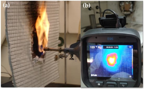
Figure 3.
(a) Flame front of sample at 920 °C, and (b) FLIR infrared camera behind sample, with temperature depending on time.
Moreover, the testing process focuses on parameters outlined by the Euroclass classification system [49], including combustibility, the presence of a single flame source, smoke generation, the emission of flaming droplets, and the consideration of the calorific value when undetermined.
Three samples of slates and laminates measuring 80 mm × 80 mm with a thickness of 13 ± 1 mm were produced for conducting fire experiments. The experiments involved exposing the samples to a 900 °C flame, generated by a Bunsen burner fuelled by propane gas, which was positioned directly in front of the sample. Throughout the test, the reducing section of the flame remained in contact with the material (as shown in Figure 3a). Temperature readings were taken on the side opposite to the fire test using an FLIR infrared camera model E95 (from FLIR Networked Systems S.L., Madrid, Spain), as illustrated in Figure 3b. Thermographic images were captured every 20 s, allowing for real-time monitoring of the fire test through 3D imaging. Temperature data were extracted from the images to plot the temperature evolution over time.
The thermal camera was calibrated beforehand using both a polished aluminium surface (with high emissivity, ε ≈ 0) and a black surface obtained by covering a plate with black insulating tape (with low emissivity, ε ≈ 1). This calibration process occurred under the same conditions as the test.
3. Results
3.1. Surface Characterisation of Slate Panels and Cork Laminate
After the treatment, the water contact angle decreased to 35° ± 5 and 20° ± 5 for cork and slate, respectively. This indicates an increase in surface energy. Slate can be considered to have a high surface energy (Table 1). However, conducting adhesion tests after simply cleaning does not yield good results due to the low polar component. After the APPT, its polar component increased along with the adhesion with the silicone adhesive. On the other hand, cork has a low surface energy with no polar component. After the APPT, its surface energy increased, especially its polar component, reaching a value sufficient for bonding.

Table 1.
Surface energy for slate panels and cork laminate.
The roughness was measured on the surface, taking Sa, equivalent to Ra, as the surface parameter. Therefore, it represents the arithmetic average of the absolute ordinate Z in the sampling area, which is approximately 2 mm2. The average value shown in Table 2 is the average of five measurements in different areas of the untreated and treated samples. The measured microroughness tends to decrease both in the slate plates and in the laminated cork, although less deviation is observed in the measurements after the APPT, indicating a more homogeneous surface. On the other hand, the roughness is greater in cork than in slate due to its cell structure, which provides more irregularities on the surface even though it is embedded with a resin. The 3D images (Figure 4) do not show any difference between the untreated and treated samples beyond those due to the morphology of the material.

Table 2.
Average roughness (Sa) for slate panels and cork laminate.
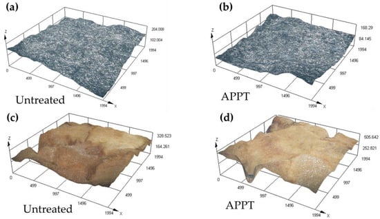
Figure 4.
Three-dimensional digital microscope images of (a) untreated slate surface and (b) slate surface treated with APPT. (c) Untreated cork structures and (d) cork structures treated with APPT. All axes are in µm.
3.2. Mechanical Characterisation of Slate and Silicone Adhesive
To characterise slate, flexural and Charpy impact tests were conducted. Slate is a heterogeneous material with a lot of irregularities on its surface and with possible internal delamination, which increased the dispersion in the tests. Additionally, since it is a ceramic material, it shows brittleness, which can be seen in its high flexural strength and very low deformation (Table 3 and Figure 5). Therefore, slate also has little resistance when subjected to impact, with a resilience of 0.29 J/cm2 ± 0.19 (Figure 6).

Table 3.
Average flexural strength, strain, and modulus of slate samples.
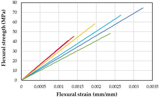
Figure 5.
Flexural tests for six slate samples, each line corresponds to a tested slate sample.
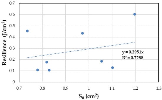
Figure 6.
Charpy impact tests for eight slate samples at room temperature.
When studying silicone’s adhesive properties, according to the results in Table 4 and Figure 7, it is classified as a viscoelastic material with a tensile strength and Young’s modulus of 597 MPa and 54 MPa, respectively, and a high tensile strain (267%). Both the strength and strain of the material show considerable deviations, probably because of the presence of small air bubbles trapped within the samples. These bubbles are likely formed during the skin formation process, preventing the air from escaping.

Table 4.
Average tensile strength, strain, and Young’s modulus for silicone samples.
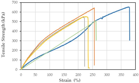
Figure 7.
Tensile tests for five silicone samples, each curve corresponds to a tested silicone sample.
3.3. Drop Weight Impact and Fire Tests for Slate and Sandwich Structure
As previously mentioned, slate is known for its brittleness, making it prone to delamination and breakage after just a few impacts. Indeed, upon conducting the experiments, it was observed that all of the slate samples exhibited signs of damage after enduring three to six impacts (Figure 8a). Notably, some of the samples even experienced delamination after just two impacts (Figure 8b). Despite these challenges, the adhesive used in the experiment proved to be remarkably effective in maintaining the cohesion of the sandwich structure (Figure 9a). Remarkably, none of the materials separated during three drop impact tests, highlighting the adhesive’s ability to uphold structural integrity, as evidenced in Figure 9b, showcasing both slate (front—F) and cork (back—B).
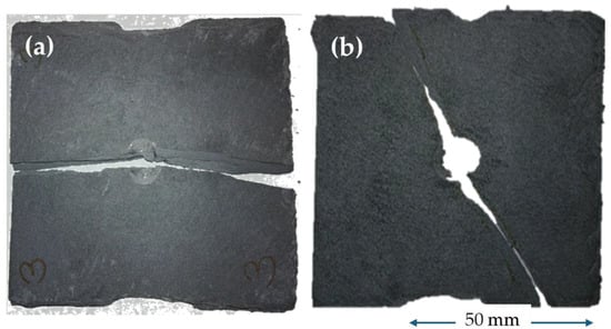
Figure 8.
Drop weight impact tests. (a) Broken slate after three impacts. (b) Delaminated slate after two impacts.
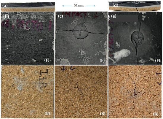
Figure 9.
Drop weight impact tests for sandwich structure. (a) Sandwich structure profile before impact; (b) sandwich structure after two impacts: (F) front side and (B) back side. (c) Sandwich structure after twenty-five impacts: (F) front side and (B) back side. (d) Sandwich structure profile after two hundred and fifteen impacts. (e) Sandwich structure after two hundred and fifteen impacts: (F) front side and (B) back side.
Furthermore, it was observed that even after enduring 25 impacts, the sandwich structure did not exhibit signs of delamination or breakage (Figure 9c). Impressively, even after subjecting the sample to 215 impacts, no detachment was observed (Figure 9d,e), depicting both the front (F) and back (B) sides.
The results of the fire test for the sandwich structure depicted in both Figure 10 and Figure 11 unveil an intriguing relationship between temperature and slate thickness. Notably, thinner slate exhibits a greater propensity for temperature transmission through its surface. For instance, in the case of a 4.65 mm thick slate, the temperature soared to 462 °C (Figure 10a), whereas for a 6.25 mm thick slate, the temperature peaked at 423 °C (Figure 10b). This discrepancy highlights the influence of slate thickness on its thermal behaviour.
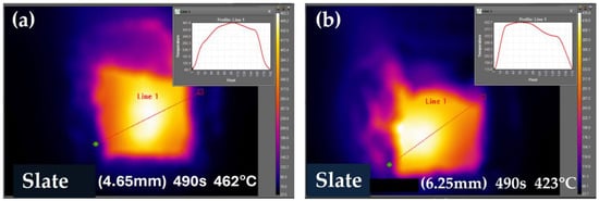
Figure 10.
Thermographs corresponding to (a) 4.65 mm thick slate and (b) 6.25 mm thick slate.
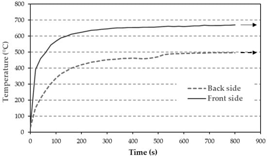
Figure 11.
Fire test for 5 mm thick slate, back side and front side (face where flame hits directly). The arrows indicate the test can continue at the same temperature.
Interestingly, while the face directly exposed to the flame registered temperatures reaching around 700 °C, the opposite face recorded a maximum temperature of approximately 500 °C. This stark contrast underscores the thermal insulation properties of slate. Over a period of 14 min, the slate can reduce the temperature by 200 °C, which is a phenomenon that was particularly evident in the 5 mm thick slate (Figure 11).
In the case of the sandwich structure, temperature increase occurs more gradually (Figure 12). The temperature rise during the initial minutes of the test is slower in specimens with thicker slate. Conversely, thinner slate results in a higher maximum test temperature being reached more rapidly.
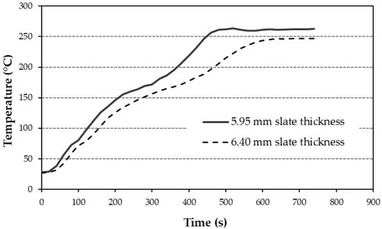
Figure 12.
Fire tests for sandwich structures with 5.95 mm and 6.40 mm slate thicknesses. The temperature corresponds to the back part where the cork is located.
The maximum temperature reached on the opposite face of the flame was approximately 260 °C, as depicted in Figure 13a–c. Figure 13a corresponds to the thermograph, Figure 13b displays the temperature profile along the straight line of Figure 13a, and Figure 13c provides a magnified view of the temperature scale observed on the right side of Figure 13a. As the specimen was heated up, progressive ballooning of the cork plate was observed (Figure 13d). Testing concluded upon the observation of cork degradation. The darkened part of the cork resulted from the smoke generated in the final moments before extinguishing the flame, approximately at 15 min. At this point, degradation and debonding of the adhesive were observed at a temperature exceeding 325 °C, which caused the termination of the tests at 12 min.
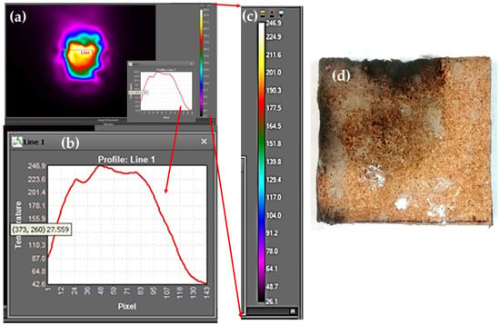
Figure 13.
(a) Thermographs corresponding to cork at 600 s of test. (b) Temperature profile in line 1 of thermographs (a) with maximum temperature of 246.9 °C, (c) temperature scale in relation with the hot area, and (d) cork macrographic after 600 s of test.
Figure 14 displays a series of thermograms captured at various test times on the cork section, specifically at the rear of the flame incidence. The temperature indicated in the upper left corner of each thermogram corresponds to the location marked by a cross. The maximum temperature on the plate is represented in the upper right corner and aligns with the brightest region of the cork surface. The sequence illustrates the progressive increase in temperature, which was initially rapid and later slowed down, which is consistent with the observations made from Figure 12. This test lasted for 12.30 min (740 s), reaching a maximum temperature of 251 °C.
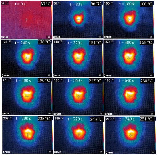
Figure 14.
A sequence of thermographs corresponding to the opposite side of the fire test conducted on the cork. The temperature at the top left corresponds to the temperature of the cross in the centre of the sample, and the temperature at the top right is the temperature of the brightest part in the hottest area.
4. Discussion
The two adherents that form the sandwich require a surface treatment to bond together using silicone because of their low polar surface energies. The APPT was chosen for its ecological merits, as it uses air as a gas to generate plasma, operates at low temperatures to avoid causing damage to the cork surface, and does not emit contaminants or residues [67]. Additionally, it can be easily integrated into an assembly line for laminate production.
After the APPT, the water contact angles decreased by 55% for slate and 63% for cork, corresponding to increases of 14% and 39% in surface energy for slate and cork, respectively (Table 1). The explanation for why slate, despite being ceramic, exhibits poor adhesion with silicone cannot solely be attributed to low surface energy. Initially, it possesses a polar component that could theoretically facilitate good adhesion. Therefore, the surface energy was also assessed using the acid–base method, which offers insights into acid, base, and Lewis components [68,69]. In this method, a high basic component is desirable, indicating the presence of Si-O− bonds on the surface derived from mica and feldspar silicates, as well as quartz silica. This basic component increased from 30 mN/m to 87 mN/m post-treatment, representing a 65% augmentation in the Si-O− groups on the surface.
Plasma treatment also affects the surface roughness, particularly in terms of homogeneity. The treatment tends to make the roughness more uniform and enhances it at the nanometer scale [70,71]. In this case, although the roughness slightly decreases, it still provides sufficient bonding capability for silicone (Figure 4 and Table 2). Additionally, since silicone is highly viscous, it requires a smoother surface without large peaks to ensure optimal contact with the material.
Slate is a natural ceramic material known for its brittleness, with a flexural modulus of 27 GPa and a flexural strength of 56 MPa (Table 3 and Figure 5). It is even more rigid than some construction materials that have been studied in recent research. For instance, Alomayri [72] investigated geopolymers containing 2% Al2O3, which exhibited a flexural modulus of 0.330 GPa and a flexural strength of 4.5 MPa. Similarly, Soltani et al. [73] explored ordinary Portland cements enhanced with clinoptilolite and silica fume, achieving a maximum flexural modulus of up to 7 GPa with a 30% cement replacement. Additionally, slate’s resistance to impact (Figure 6) is also low, with a resilience of 0.27 J/cm2, which confirms its fragility.
On the other hand, silicones stand out among polymeric systems due to their unique characteristics. They are the only commercially available inorganic polymers, offering low modulus and versatility in formulation and curing techniques. This makes them suitable for diverse applications [74]. Often referred to as hyper-elastic materials due to their rubber-like mechanical properties [75], silicones can also be engineered to be flame-retardant by incorporating fillers [76]. For instance, silicone sprays can be used to fill firewalls [77]. This adaptability means that silicone used with a specific modulus, high deformation (Table 4 and Figure 7), and temperature resistance (working continuously up to 325 °C and occasionally up to 350 °C) may be tailored to meet different requirements, whether it is enhanced elasticity or greater resistance to high temperatures.
The drop impact test further highlighted the fragility of slate, which is prone to fracturing or delamination after impacts (Figure 8a,b). The composition of slate consists of layers with abundant metallic minerals, attributed to its natural origin [78]. As these layers start to separate, the delamination process occurs. This phenomenon can occur due to impacts, ageing, or harsh weather conditions affecting the slate [20].
In summary, despite the inherent brittleness of slate, the adhesive used in the sandwich structure (Figure 9a) demonstrated remarkable effectiveness in enhancing cohesion and durability (Figure 9b,d,e). This was evident in the resilience of the laminate even after enduring numerous impacts, underscoring its suitability for various applications requiring robust materials.
The explanation for the improvement that occurs when slate is reinforced can be found in the way in which the mechanical waves of tension and compression are transmitted through the materials. In the case of slate plates, the incident energy remains consistent across all specimens. The slate specimen absorbs more energy for the generation and development of cracks, resulting in decreased reflected and transmitted energy. However, in the sandwich structure, silicone and cork materials are more deformable, resulting in higher strain. As a consequence, transmitted energy increases, while reflected and absorbed energies are reduced [79].
The fire test was conducted on both slate (Figure 10 and Figure 11) and the sandwich structure (Figure 12 and Figure 13). It is noted that thermal conductivity typically rises with temperature [52]. If there is an increase in thermal conductivity within the slate, it could significantly impact the sandwich panel. However, based on the fire test conducted solely on the slate (Figure 11), the temperature on the opposite side at the flame reached 400 °C in three minutes and steadily climbed to 500 °C by 10 min, stabilising for the remainder of the test. This gradual increase could be attributed to a change in the thermal conductivity. According to Boutinguiza et al. [22], the thermal conductivity of slate, calculated by thermal diffusivity (2.27 ± 0.30 mm2/s) and a heat capacity ranging from 25 °C to 500 °C (mean value of 0.96 ± 0.04 kJ/kg K), was 2.00 ± 0.20 W/m K, which is a value similar to that obtained at 25 °C.
On the other hand, in the fire test conducted on the sandwich panel, the cork began to deteriorate at 260 °C after 11 min (Figure 12). When the test continued, the cork only darkened (without burning, as shown in Figure 13d) when the silicone debonded, which occurred at nearly 350 °C. Consequently, an increase in the thermal conductivity of the cork would not significantly affect the test results.
It has been demonstrated that the overall impact resistance of the assembly is significantly higher. However, in the event of a fire, it is essential to consider the diverse classifications of each component and understand the behaviour of each material as a whole.
Slate typically holds a Euroclass A1 classification, indicating that it is non-combustible, prevents fire penetration, emits minimal smoke (s1), and does not drip (d0). As per the supplier, silicone carries a Euroclass M2 classification, indicating that it is combustible but with low flammability. Lastly, laminated cork, according to its manufacturer, is classified as Euroclass D, indicating a moderate fire contribution.
The tests were conducted over a duration of 12 min, reaching a temperature of 260 °C on the side opposite to the flame. At this time and temperature, the cork did not exhibit signs of deterioration, smoking, or dripping. Similarly, no smoke or drips were observed from the silicone adhesive. However, during longer test durations, such as 15 min, degradation of the silicone adhesive occurred, particularly debonding, although no dripping was evident. Nonetheless, some smoke was emitted, resulting in the darkening of the cork due to a crack induced by the heat exceeding 325 °C, which corresponds to the continuous operating temperature of silicone.
Based on these observations, it is reasonable to consider the sandwich construction as being flame-retardant and capable of containing frontal fire for a certain duration. Therefore, this composite material may be classified as B-s1-d0 within a specified time frame.
This classification applies to a structure comprising slate, silicone, and cork layers, where a temperature gradient of nearly 700 °C exists between the direct fire and the cork layer. The cork layer showed no signs of deterioration until approximately 11 min, after which the silicone layer also began to degrade. This flame-retardant composite can effectively safeguard habitats from exterior fires in rural or countryside settings, affording occupants ample time to evacuate.
In line with the objective of this work, our aim is to manufacture a sandwich structure comprising slate–cork–slate bonded with silicone. However, alternative configurations such as slate–cork–concrete or other construction materials are also viable options. Notably, if the slate and cork panel exhibits flame retardancy, it is reasonable to expect improved performance from the other panels as well.
5. Conclusions
In light of the results and the discussion presented in this work, a sandwich structure comprising slate–cork–slate bonded with silicone was developed and proven to be a viable flame-retardant composite material. Both the slate and cork were required to be treated with APPT to bond effectively with silicone. Although the roughness was maintained, the polar component of surface energy increased. The sandwich structure exhibited enhanced cohesion and durability with increased impact resistance compared to pristine slate. Additionally, fire tests revealed the flame-retardant capabilities of the sandwich structure, warranting its classification as Euroclass B-si-do.
Author Contributions
Conceptualisation, J.A. and M.A.M.; methodology, J.A. and M.A.M.; software, J.A.; validation, J.A., S.L.d.A. and M.A.M.; formal analysis, J.A. and M.A.M.; investigation, J.A., S.L.d.A. and M.A.M.; resources, M.A.M.; data curation, J.A.; writing—original draft preparation, J.A.; writing—review and editing, J.A., S.L.d.A. and M.A.M.; visualisation, J.A. and M.A.M.; supervision, M.A.M.; project administration, M.A.M.; All authors have read and agreed to the published version of the manuscript.
Funding
This research received no external funding.
Institutional Review Board Statement
This study did not require ethical approval.
Informed Consent Statement
This is not applicable.
Data Availability Statement
The data files from the utilised equipment, along with the Excel or Origin files used for the calculations, are available upon specific request for any researchers or reviewers wishing to consult them.
Acknowledgments
We would like to thank the laboratory technicians at the Mechanical Engineering Department of the ICAI, the laboratory of the Materials Science and Engineering Department at the Carlos III University of Madrid, and SIKA S.A.U for their advice and for providing the silicones for this work.
Conflicts of Interest
The authors declare no conflicts of interest.
References
- Parlamento Europeo de la, U.E. Directive (EU) 2023/1791 of the European Parliament and of the Council of 13 September 2023 on Energy Efficiency and Amending Regulation (EU) 2023/955 (Recast) (Text with EEA Relevance). Off. J. Eur. Union 2023, L 231, 1–111. [Google Scholar]
- Debecker, B.; Vervoort, A. Experimental Observation of Fracture Patterns in Layered Slate. Int. J. Fract. 2009, 159, 51–62. [Google Scholar] [CrossRef]
- Gholami, R.; Rasouli, V. Mechanical and Elastic Properties of Transversely Isotropic Slate. Rock Mech. Rock Eng. 2014, 47, 1763–1773. [Google Scholar] [CrossRef]
- Stoeckhert, F.; Molenda, M.; Brenne, S.; Alber, M. Fracture Propagation in Sandstone and Slate—Laboratory Experiments, Acoustic Emissions and Fracture Mechanics. J. Rock Mech. Geotech. Eng. 2015, 7, 237–249. [Google Scholar] [CrossRef]
- Muñoz-Ibáñez, A.; Delgado-Martín, J.; Costas, M.; Rabuñal-Dopico, J.; Alvarellos-Iglesias, J.; Canal-Vila, J. Pure Mode I Fracture Toughness Determination in Rocks Using a Pseudo-Compact Tension (PCT) Test Approach. Rock Mech. Rock Eng. 2020, 53, 3267–3285. [Google Scholar] [CrossRef]
- Alejano, L.R.; González-Fernández, M.A.; Estévez-Ventosa, X.; Song, F.; Delgado-Martín, J.; Muñoz-Ibáñez, A.; González-Molano, N.; Alvarellos, J. Anisotropic Deformability and Strength of Slate from NW-Spain. Int. J. Rock Mech. Min. Sci. 2021, 148, 104923. [Google Scholar] [CrossRef]
- Li, E.; Wei, Y.; Chen, Z.; Zhang, L. Experimental and Numerical Investigations of Fracture Behavior for Transversely Isotropic Slate Using Semi-Circular Bend Method. Appl. Sci. 2023, 13, 2418. [Google Scholar] [CrossRef]
- Zhao, N.N.; Feng, J.L. Investigation on Fracture Mechanism of Layered Slate: Experiment and Beam-Particle Method. Environ. Earth Sci. 2021, 80, 1–28. [Google Scholar] [CrossRef]
- Kang, X.; Gan, Y.; Chen, R.; Zhang, C. Sustainable Eco-Friendly Bricks from Slate Tailings through Geopolymerization: Synthesis and Characterization Analysis. Constr. Build. Mater. 2021, 278, 122337. [Google Scholar] [CrossRef]
- Samper, M.D.; Petrucci, R.; Sánchez-Nacher, L.; Balart, R.; Kenny, J.M. New Environmentally Friendly Composite Laminates with Epoxidized Linseed Oil (ELO) and Slate Fiber Fabrics. Compos. Part B Eng. 2015, 71, 203–209. [Google Scholar] [CrossRef]
- Gwyn, D. Slate Production. In The Oxford Handbook of Industrial Archaeology; Colin Casella, E., Nevell, M., Steyne, H., Eds.; Oxford University Press: Oxford, UK, 2022; pp. 58–73. ISBN 9780199693962. [Google Scholar]
- Anderson, T.; Madenci, E. Experimental Investigation of Low-Velocity Impact Characteristics of Sandwich Composites. Compos. Struct. 2000, 50, 239–247. [Google Scholar] [CrossRef]
- Herzog, R.F.; Morrison, S.J.; Patnode, S.A.; Green, J.R. Ice Ball Impact Testing of Siding. In Proceedings of the Adressing the Building Envelope—27th RCI International Convention and Trade Show, Dallas, TX, USA, 15–20 March 2012; Haag Engineering Co.: Burnsville, MN, USA, 2012; pp. 141–146. [Google Scholar]
- Standard Test Method for Materials Attached to Vertical or Near Vertical Surfaces and Their Resistance to Horizontally Propelled Freezer Ice Balls; Debris Impact Facility: Lubbock, TX, USA, 2015.
- Lemmos, L. Asphalt Magazine; Asphalt Institute: Lexington, KY, USA, 2022. [Google Scholar]
- Cárdenes, V.; Cnudde, J.P.; Wichert, J.; Large, D.; López-Mungira, A.; Cnudde, V. Roofing Slate Standards: A Critical Review. Constr. Build. Mater. 2016, 115, 93–104. [Google Scholar] [CrossRef]
- Garcia-Fernandez, C.C.; Alvarez-Fernandez, M.I.; Cardoso, R.; Gonzalez-Nicieza, C. Effect of Environmental Relative Humidity in the Tensile Strength of Layering in Slate Stone. Bull. Eng. Geol. Environ. 2020, 79, 1399–1411. [Google Scholar] [CrossRef]
- Sitzia, F.; Lisci, C.; Pires, V.; Alves, T.; Mirão, J. Laboratorial Simulation for Assessing the Performance of Slates as Construction Materials in Cold Climates. Appl. Sci. 2023, 13, 2761. [Google Scholar] [CrossRef]
- Sánchez-Soto, P.J.; Ruiz-Conde, A.; Bono, R.; Raigón, M.; Garzón, E. Thermal Evolution of a Slate. J. Therm. Anal. Calorim. 2007, 90, 133–141. [Google Scholar] [CrossRef]
- Cárdenes, V.; Rubio-Ordóñez, A.; García-Guinea, J. Fire Resistance of Roofing Slates: Mechanical, Mineralogical and Aesthetic Changes alongside Temperature Increase. Constr. Build. Mater. 2023, 368, 130376. [Google Scholar] [CrossRef]
- EN 12326:2015; Slate and Stone for Discontinuous Roofing and External Cladding—Part 1 and 2. European Committee for Standardization: Brussels, Belgium, 2015.
- Boutinguiza, M.; Lusquiños, F.; Pou, J.; Soto, R.; Quintero, F.; Comesaña, R. Thermal Properties Measurement of Slate Using Laser Flash Method. Opt. Lasers Eng. 2012, 50, 727–730. [Google Scholar] [CrossRef]
- APCOR Information Bureau 2019—Cork Sector in Numbers; APCOR: Doorwerth, The Netherlands, 2019.
- Pereira, H. Variability of the Chemical Composition of Cork. BioResources 2013, 8, 2246–2256. [Google Scholar] [CrossRef]
- Knapic, S.; Oliveira, V.; Machado, J.S.; Pereira, H. Cork as a Building Material: A Review. Eur. J. Wood Wood Prod. 2016, 74, 775–791. [Google Scholar] [CrossRef]
- Castro, O.; Silva, J.M.; Devezas, T.; Silva, A.; Gil, L. Cork Agglomerates as an Ideal Core Material in Lightweight Structures. Mater. Des. 2010, 31, 425–432. [Google Scholar] [CrossRef]
- Sergi, C.; Sarasini, F.; Russo, P.; Vitiello, L.; Barbero, E.; Sanchez-Saez, S.; Tirillò, J. Effect of Temperature on the Low-Velocity Impact Response of Environmentally Friendly Cork Sandwich Structures. J. Sandw. Struct. Mater. 2022, 24, 1099–1121. [Google Scholar] [CrossRef]
- Sergi, C.; Sarasini, F.; Tirillò, J. The Compressive Behavior and Crashworthiness of Cork: A Review. Polymers 2022, 14, 134. [Google Scholar] [CrossRef] [PubMed]
- Mahalle, L. A Comparative Life Cycle Assessment of Canadian Hardwood Flooring with Alternative Flooring Types; FP Innovations: Vancouver, BC, Canada, 2011. [Google Scholar]
- Demertzi, M.; Garrido, A.; Dias, A.C.; Arroja, L. Environmental Performance of a Cork Floating Floor. Mater. Des. 2015, 82, 317–325. [Google Scholar] [CrossRef]
- Pargana, N.; Pinheiro, M.D.; Silvestre, J.D.; De Brito, J. Comparative Environmental Life Cycle Assessment of Thermal Insulation Materials of Buildings. Energy Build. 2014, 82, 466–481. [Google Scholar] [CrossRef]
- Sierra-Pérez, J.; Boschmonart-Rives, J.; Dias, A.C.; Gabarrell, X. Environmental Implications of the Use of Agglomerated Cork as Thermal Insulation in Buildings. J. Clean. Prod. 2016, 126, 97–107. [Google Scholar] [CrossRef]
- Mestre, A.; Vogtlander, J. Eco-Efficient Value Creation of Cork Products: An LCA-Based Method for Design Intervention. J. Clean. Prod. 2013, 57, 101–114. [Google Scholar] [CrossRef]
- Mestre, A. A Design Action Intervention Approach in the Cork Industry towards Sustainable Product Innovation. J. Des. Res. 2015, 13, 185–235. [Google Scholar] [CrossRef]
- Demertzi, M.; Paulo, J.A.; Faias, S.P.; Arroja, L.; Dias, A.C. Evaluating the Carbon Footprint of the Cork Sector with a Dynamic Approach Including Biogenic Carbon Flows. Int. J. Life Cycle Assess. 2018, 23, 1448–1459. [Google Scholar] [CrossRef]
- Tártaro, A.S.; Mata, T.M.; Martins, A.A.; Esteves da Silva, J.C.G. Carbon Footprint of the Insulation Cork Board. J. Clean. Prod. 2017, 143, 925–932. [Google Scholar] [CrossRef]
- Rives, J.; Fernandez-Rodriguez, I.; Rieradevall, J.; Gabarrell, X. Environmental Analysis of the Production of Natural Cork Stoppers in Southern Europe (Catalonia-Spain). J. Clean. Prod. 2011, 19, 259–271. [Google Scholar] [CrossRef]
- Reis, S.F.; Lopes, P.; Roseira, I.; Cabral, M.; Mateus, N.; Freitas, V. Recovery of Added Value Compounds from Cork Industry By-Products. Ind. Crops Prod. 2019, 140, 111599. [Google Scholar] [CrossRef]
- Ramos, A.; Berzosa, J.; Clarens, F.; Marin, M.; Rouboa, A. Environmental and Socio-Economic Assessment of Cork Waste Gasification: Life Cycle and Cost Analysis. J. Clean. Prod. 2020, 249, 119316. [Google Scholar] [CrossRef]
- Novais, R.M.; Carvalheiras, J.; Senff, L.; Lacasta, A.M.; Cantalapiedra, I.R.; Giro-Paloma, J.; Seabra, M.P.; Labrincha, J.A. Multifunctional Cork—Alkali-Activated Fly Ash Composites: A Sustainable Material to Enhance Buildings’ Energy and Acoustic Performance. Energy Build. 2020, 210, 109739. [Google Scholar] [CrossRef]
- Samuel, D.M.; Inumerable, N.; Stumpf, A.; Kriven, W.M. Thermal Conductivity of Several Geopolymer Composites and Discussion of Their Formulation. Int. J. Appl. Ceram. Technol. 2023, 20, 475–486. [Google Scholar] [CrossRef]
- Amaro, A.M.; Reis, P.N.B.; Ivañez, I.; Sánchez-Saez, S.; Garcia-Castillo, S.K.; Barbero, E. The High-Velocity Impact Behaviour of Kevlar Composite Laminates Filled with Cork Powder. Appl. Sci. 2020, 10, 6108. [Google Scholar] [CrossRef]
- Barbosa, A.Q.; da Silva, L.F.M.; Abenojar, J.; Figueiredo, M.; Öchsner, A. Toughness of a Brittle Epoxy Resin Reinforced with Micro Cork Particles: Effect of Size, Amount and Surface Treatment. Compos. Part B Eng. 2017, 114, 299–310. [Google Scholar] [CrossRef]
- Pereira, H. The Rationale behind Cork Properties: A Review of Structure and Chemistry. BioResources 2015, 10, 6207–6229. [Google Scholar] [CrossRef]
- Moreira, R.A.S.; De Melo, F.J.Q.; Dias Rodrigues, J.F. Static and Dynamic Characterization of Composition Cork for Sandwich Beam Cores. J. Mater. Sci. 2010, 45, 3350–3366. [Google Scholar] [CrossRef]
- Ptak, M.; Kaczynski, P.; Fernandes, F.A.O.; de Sousa, R.J.A. Assessing Impact Velocity and Temperature Effects on Crashworthiness Properties of Cork Material. Int. J. Impact Eng. 2017, 106, 238–248. [Google Scholar] [CrossRef]
- Sanchez-Saez, S.; García-Castillo, S.K.; Barbero, E.; Cirne, J. Dynamic Crushing Behaviour of Agglomerated Cork. Mater. Des. 2015, 65, 743–748. [Google Scholar] [CrossRef]
- Arteiro, A.; Reis, A.L.M.A.; Nóvoa, P.J.R.O.; Silva, L.F.M.; Zupan, M.; Marques, A.T. Low Velocity Impact and Flexural Performance of Sandwich Structures with Cork and Polymer Foam Cores. Cienc. Tecnol. Mater. 2013, 25, 79–84. [Google Scholar] [CrossRef]
- EN 13501-1:2019; Fire Classification of Construction Products and Building Elements—Part 1: Classification Using Data from Reaction to Fire Tests. European Committee for Standardization: Brussels, Belgium, 2019.
- Silva, S.P.; Sabino, M.A.; Fernandas, E.M.; Correlo, V.M.; Boesel, L.F.; Reis, R.L. Cork: Properties, Capabilities and Applications. Int. Mater. Rev. 2005, 50, 345–365. [Google Scholar] [CrossRef]
- Ma, W.; Elkin, R. Sandwich Structural Composites: Theory and Practice, 1st ed.; Ma, W., Elkin, R., Eds.; CRC Press: Boca Raton, FL, USA, 2022; ISBN 978-0-367-44172-2. [Google Scholar]
- Fu, H.; Ding, Y.; Li, M.; Li, H.; Huang, X.; Wang, Z. Research on Thermal Performance and Hygrothermal Behavior of Timber-Framed Walls with Different External Insulation Layer: Insulation Cork Board and Anti-Corrosion Pine Plate. J. Build. Eng. 2020, 28, 101069. [Google Scholar] [CrossRef]
- Akok, J.Y.; Prakask, O. Modular Construction Technique. Int. J. Eng. Sci. Res. Technol. 2017, 6, 207–209. [Google Scholar] [CrossRef]
- Senninger, S.; Breakah, T. Analyzing Methods of Prefabrication and Their Application in the Construction of Habitat for Humanity Housing. J. Archit. Civ. Eng. 2019, 4, 42–49. [Google Scholar]
- Tavares, V.; Lacerda, N.; Freire, F. Embodied Energy and Greenhouse Gas Emissions Analysis of a Prefabricated Modular House: The “Moby” Case Study. J. Clean. Prod. 2019, 212, 1044–1053. [Google Scholar] [CrossRef]
- Orhon, A.V.; Altin, M. Utilization of Alternative Building Materials for Sustainable Construction; Dincer, I., Colpan, C.O., Ezan, M.A., Eds.; Springer: Cham, Switzerland, 2019; ISBN 978-3-030-20636-9. [Google Scholar]
- Cárdenes, V.; Rubio-Ordóñez, A.; López-Munguira, A.; De la Horra, R.; Monterroso, C.; Paradelo, R.; Calleja, L. Mineralogy and Modulus of Rupture of Roofing Slate: Applications in the Prospection and Quarrying of Slate Deposits. Eng. Geol. 2010, 114, 191–197. [Google Scholar] [CrossRef]
- HSP, (Propection Fire) Fire Ratings Explained. Passive Fire Protection, Testing, and Standards. Available online: https://hspfireprotection.co.uk/information-and-advice/4_fire-ratings-explained.html (accessed on 30 March 2024).
- Abenojar, J.; Torregrosa-Coque, R.; Martínez, M.A.; Martín-Martínez, J.M. Surface Modifications of Polycarbonate (PC) and Acrylonitrile Butadiene Styrene (ABS) Copolymer by Treatment with Atmospheric Plasma. Surf. Coat. Technol. 2009, 203, 2173–2180. [Google Scholar] [CrossRef]
- Owens, D.K. Some Thermodynamic Aspects of Polymer Adhesion. J. Appl. Polym. Sci. 1970, 14, 1725–1730. [Google Scholar] [CrossRef]
- EN 828:2013; Adhesives—Wettability—Determination by Measurement of Contact Angle and Surface Free Energy of Solid Surface. European Committee for Standardization: Brussels, Belgium, 2013.
- Owens, D.K.; Wendt, R. Estimation of the Surface Free Energy of Polymers. J. Appl. Polym. Sci. 1969, 13, 1741–1747. [Google Scholar] [CrossRef]
- ISO 178:2019; Plastics—Determination of Flexural Propertiese. ISO: Geneva, Switzerland, 2019.
- ISO 179-1:2023; Plastics—Determination of Charpy Impact Properties—Part 1: Non-Instrumented Impact Test. ISO: Geneva, Switzerland, 2023.
- ISO 527-1:2019; Determination of Tensile Properties—Part 1: General Principles. ISO: Geneva, Switzerland, 2019.
- ASTM D7136:2020; Standard Test Method for Measuring the Damage Resistance of a Fiber-Reinforced Polymer Matrix Composite to a Drop-Weight Impact Event. ASTM: West Conshohocken, PA, USA, 2020.
- Encinas, N.; Díaz-Benito, B.; Abenojar, J.; Martínez, M.A. Extreme Durability of Wettability Changes on Polyolefin Surfaces by Atmospheric Pressure Plasma Torch. Surf. Coat. Technol. 2010, 205, 396–402. [Google Scholar] [CrossRef]
- Abenojar, J.; Colera, I.; Martínez, M.A.; Velasco, F. Study by XPS of an Atmospheric Plasma-Torch Treated Glass: Influence on Adhesion. J. Adhes. Sci. Technol. 2010, 24, 1841–1854. [Google Scholar] [CrossRef]
- Abenojar, J.; Martínez, M.Á.; Encinas, N.; Velasco, F. Modification of Glass Surfaces Adhesion Properties by Atmospheric Pressure Plasma Torch. Int. J. Adhes. Adhes. 2013, 44, 1–8. [Google Scholar] [CrossRef]
- Díaz-Benito, B.; Velasco, F. Atmospheric Plasma Torch Treatment of Aluminium: Improving Wettability with Silanes. Appl. Surf. Sci. 2013, 287, 263–269. [Google Scholar] [CrossRef]
- Rodríguez-Villanueva, C.; Encinas, N.; Abenojar, J.; Martínez, M.A. Assessment of Atmospheric Plasma Treatment Cleaning Effect on Steel Surfaces. Surf. Coat. Technol. 2013, 236, 450–456. [Google Scholar] [CrossRef]
- Alomayri, T. Experimental Study of the Microstructural and Mechanical Properties of Geopolymer Paste with Nano Material (Al2O3). J. Build. Eng. 2019, 25, 100788. [Google Scholar] [CrossRef]
- Soltani, A.; Tarighat, A.; Rostami, R.; Tavakoli, D.; Moradi, A. Investigation of Mechanical Properties of Concrete with Clinoptilolite and Silica Fume Using Taguchi Method. Innov. Infrastruct. Solut. 2024, 9, 1–23. [Google Scholar] [CrossRef]
- Cho, E.; Chiu, L.L.Y.; Lee, M.; Naila, D.; Sadanand, S.; Waldman, S.D.; Sussman, D. Characterization of Mechanical and Dielectric Properties of Silicone Rubber. Polymers 2021, 13, 1831. [Google Scholar] [CrossRef] [PubMed]
- Muslov, S.A.; Panin, S.V.; Zolotnitsky, I.V.; Pivovarov, A.A.; Anischenko, A.P.; Arutyunov, S.D. Mapping of Elastic and Hyperelastic Properties of the Periodontal Ligament. Mech. Compos. Mater. 2023, 59, 469–478. [Google Scholar] [CrossRef]
- Li, Y.T.; Liu, W.J.; Shen, F.X.; Zhang, G.D.; Gong, L.X.; Zhao, L.; Song, P.; Gao, J.F.; Tang, L.C. Processing, Thermal Conductivity and Flame Retardant Properties of Silicone Rubber Filled with Different Geometries of Thermally Conductive Fillers: A Comparative Study. Compos. Part B Eng. 2022, 238, 109907. [Google Scholar] [CrossRef]
- Silicones Solutions. Available online: https://siliconesolutions.com/silicone-foams.html (accessed on 4 April 2024).
- Cárdenes, V.; Ponce de León, M.; Rodríguez, X.A.; Rubio-Ordoñez, A. Roofing Slate Industry in Spain: History, Geology, and Geoheritage. Geoheritage 2019, 11, 19–34. [Google Scholar] [CrossRef]
- Ma, H.; Yue, C.; Yu, H.; Mei, Q.; Chen, L.; Zhang, J.; Zhang, Y.; Jiang, X. Experimental Study and Numerical Simulation of Impact Compression Mechanical Properties of High Strength Coral Aggregate Seawater Concrete. Int. J. Impact Eng. 2020, 137, 103466. [Google Scholar] [CrossRef]
Disclaimer/Publisher’s Note: The statements, opinions and data contained in all publications are solely those of the individual author(s) and contributor(s) and not of MDPI and/or the editor(s). MDPI and/or the editor(s) disclaim responsibility for any injury to people or property resulting from any ideas, methods, instructions or products referred to in the content. |
© 2024 by the authors. Licensee MDPI, Basel, Switzerland. This article is an open access article distributed under the terms and conditions of the Creative Commons Attribution (CC BY) license (https://creativecommons.org/licenses/by/4.0/).