


Fire Protection of Steel Structures of Oil and Gas Facilities: Multilayer, Removable, Non-Combustible Covers


Abstract
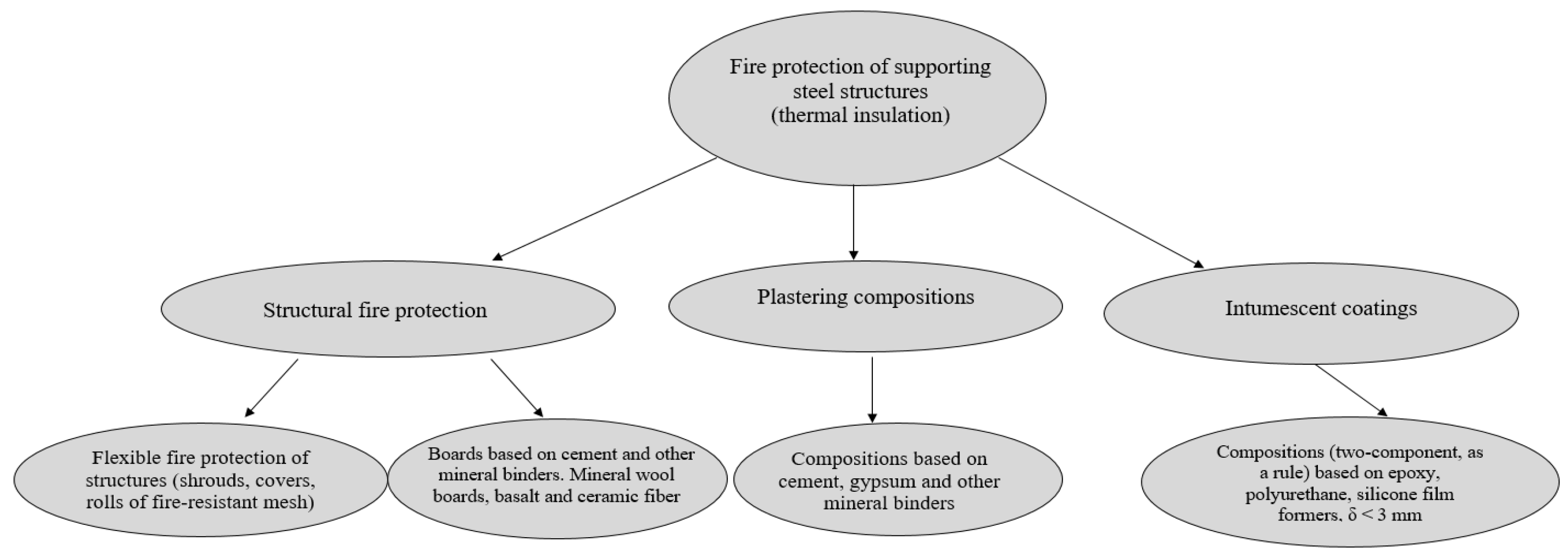
1. Introduction
2. Materials and Methods
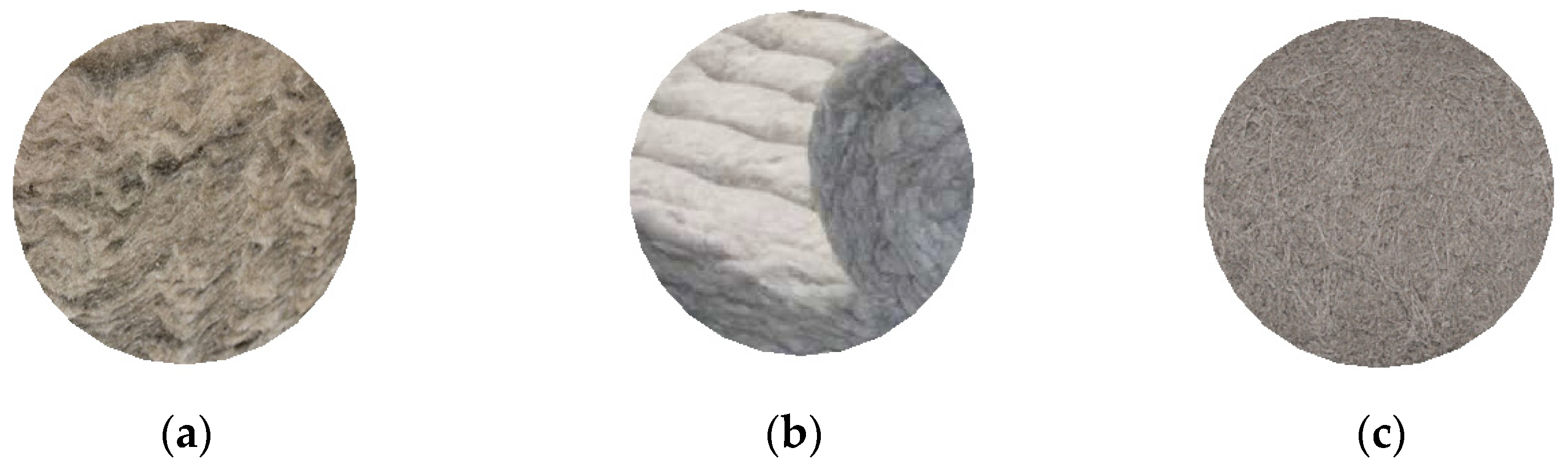
2.1. Materials
2.2. Methods
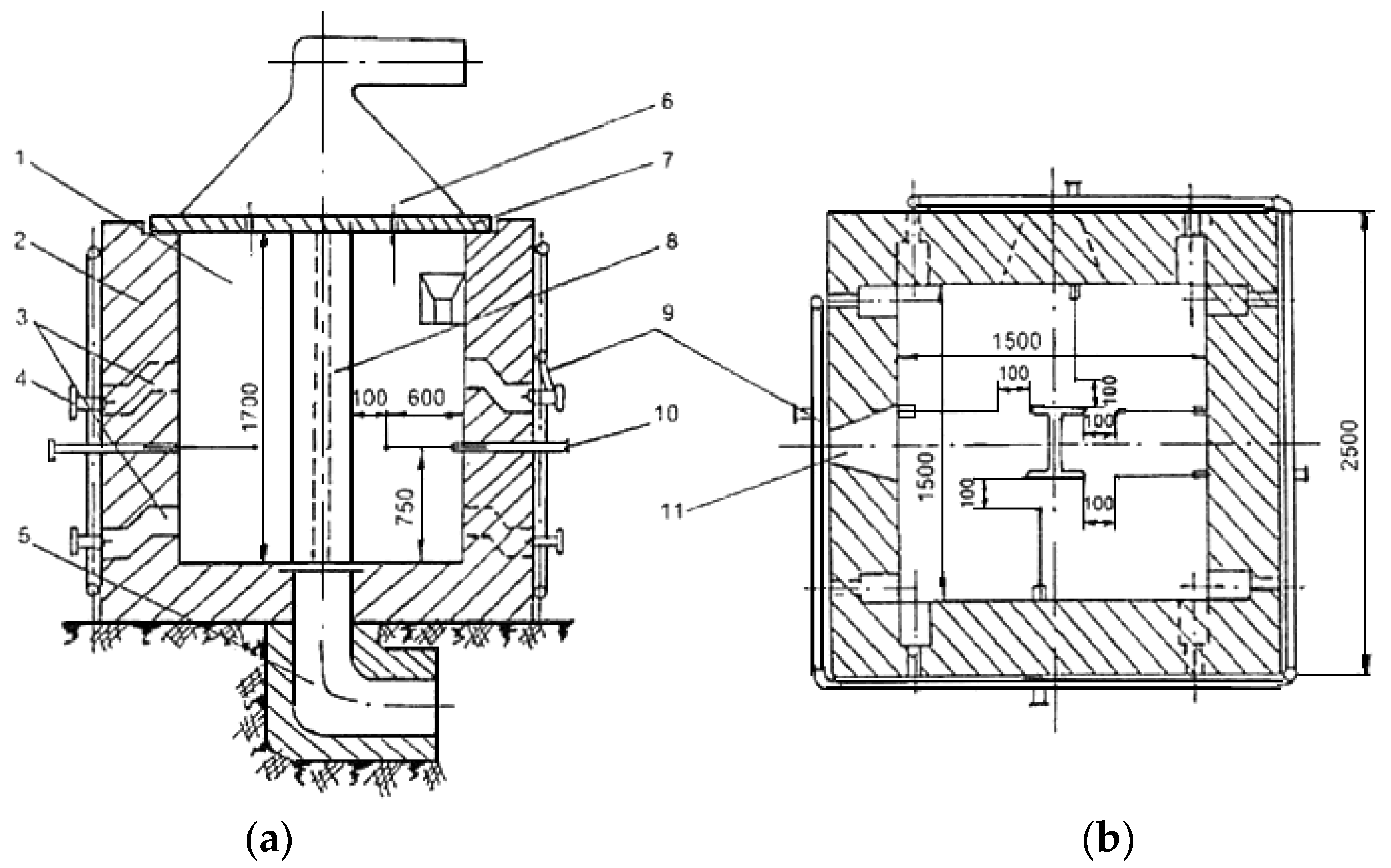
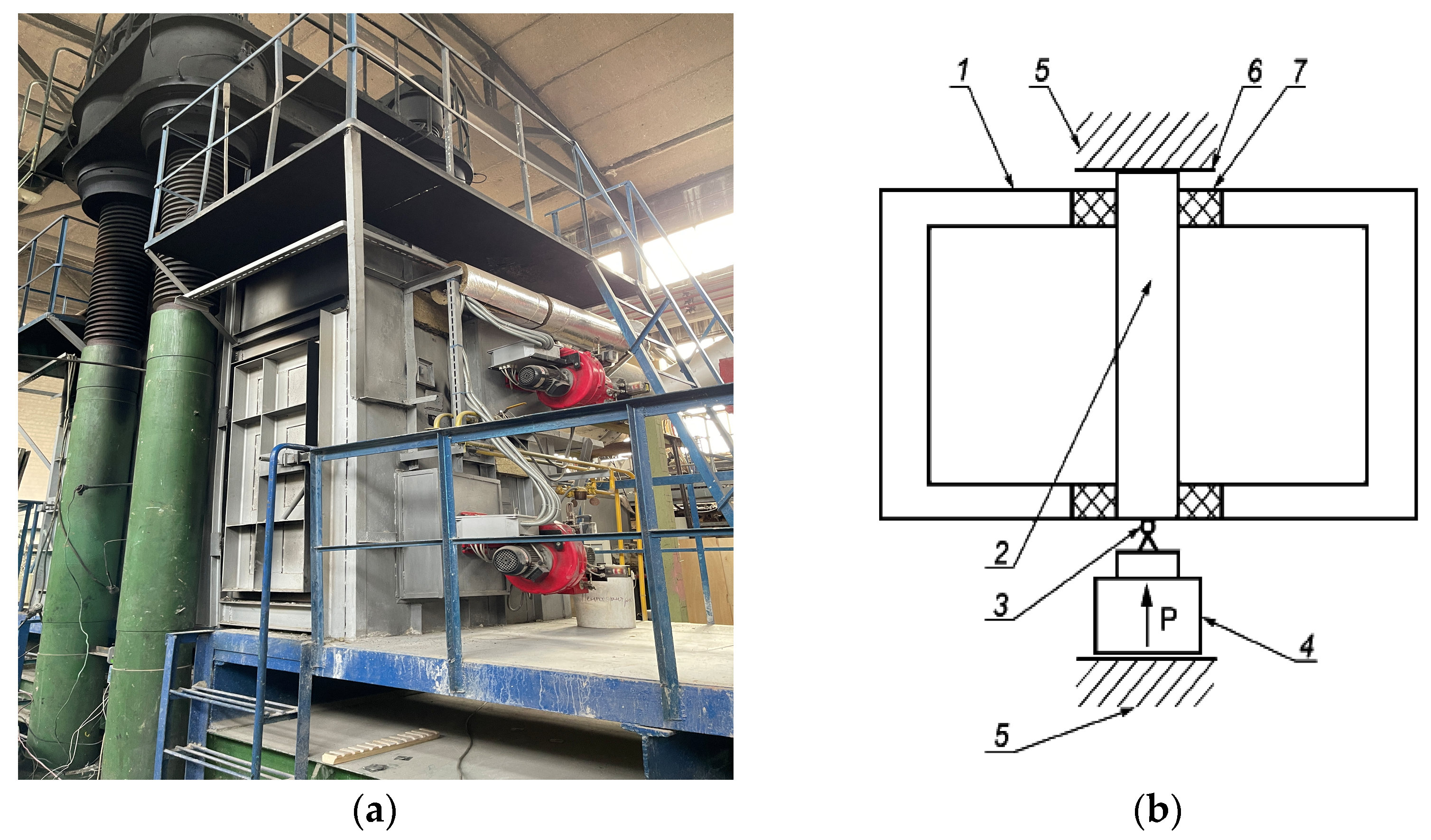
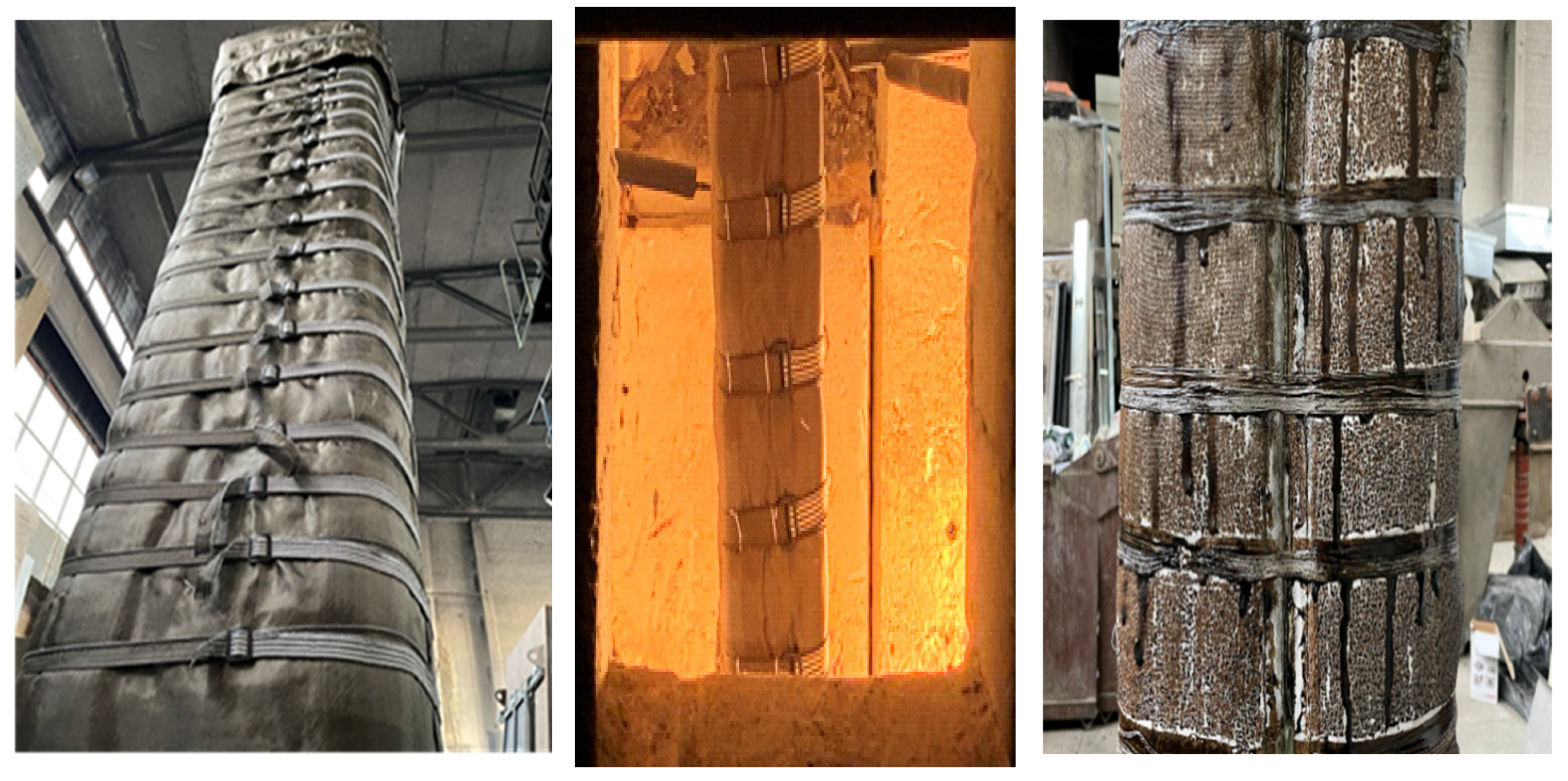
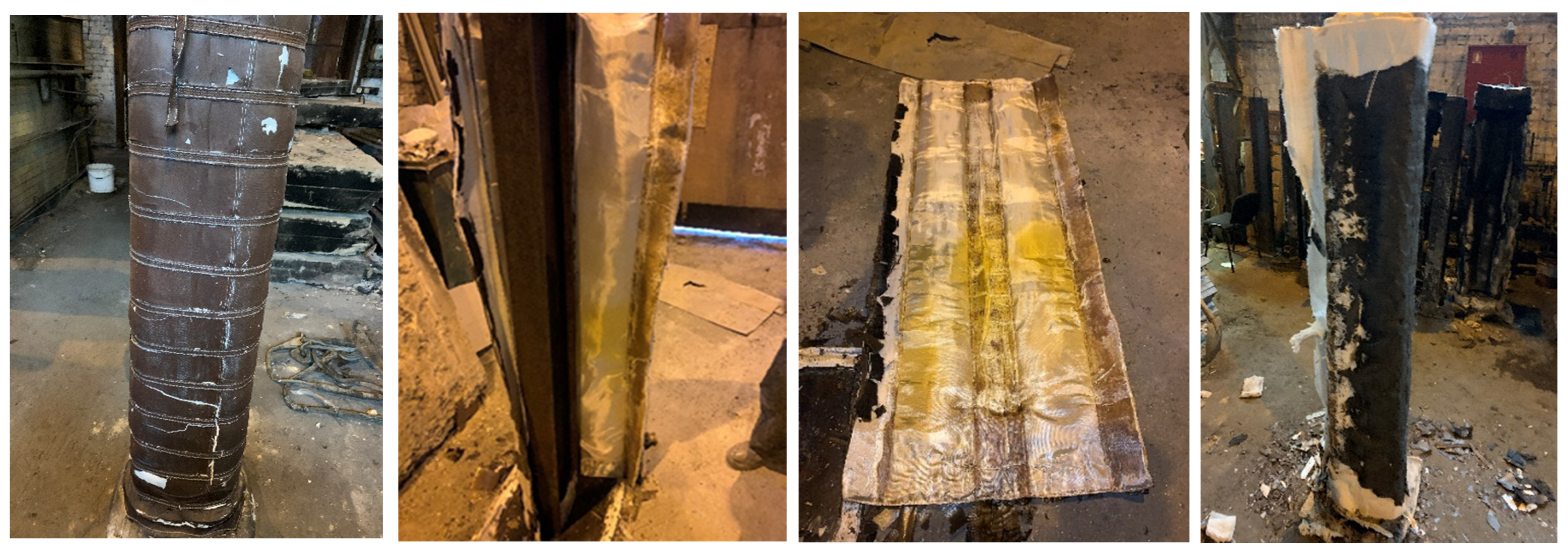
2.2.1. Experimental Studies
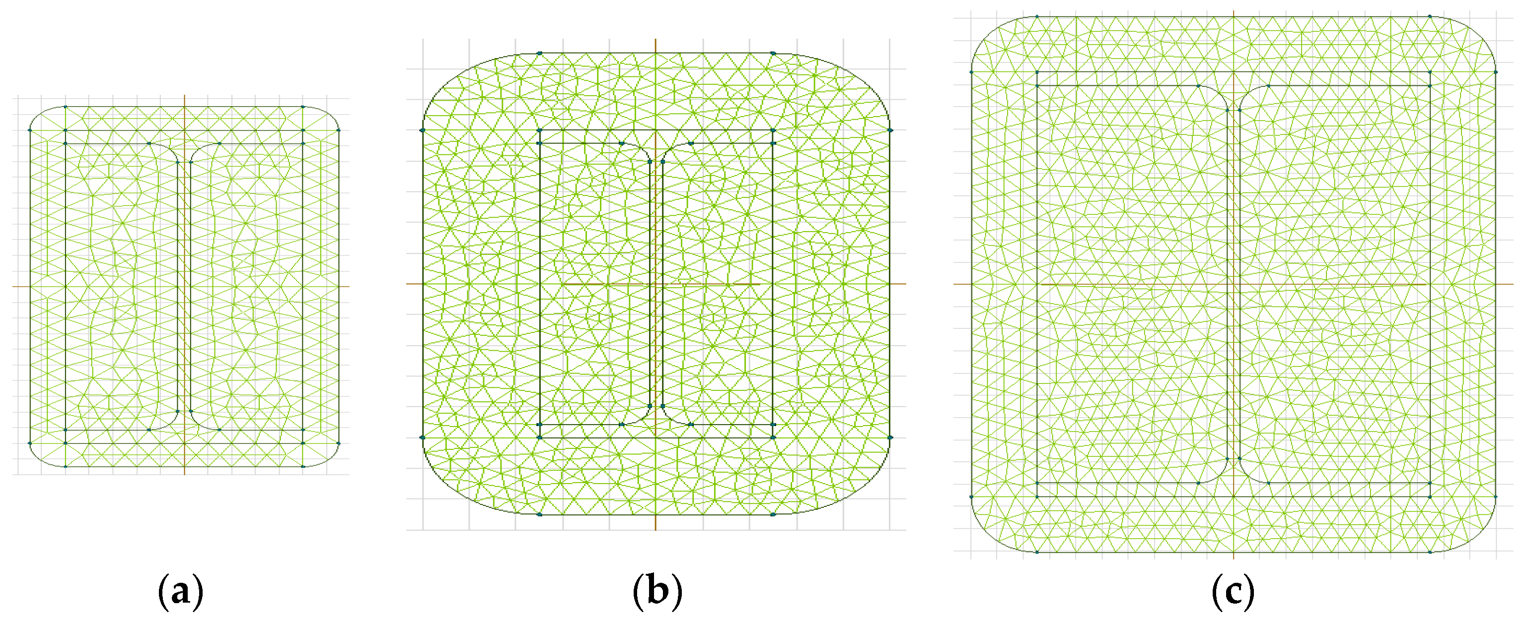
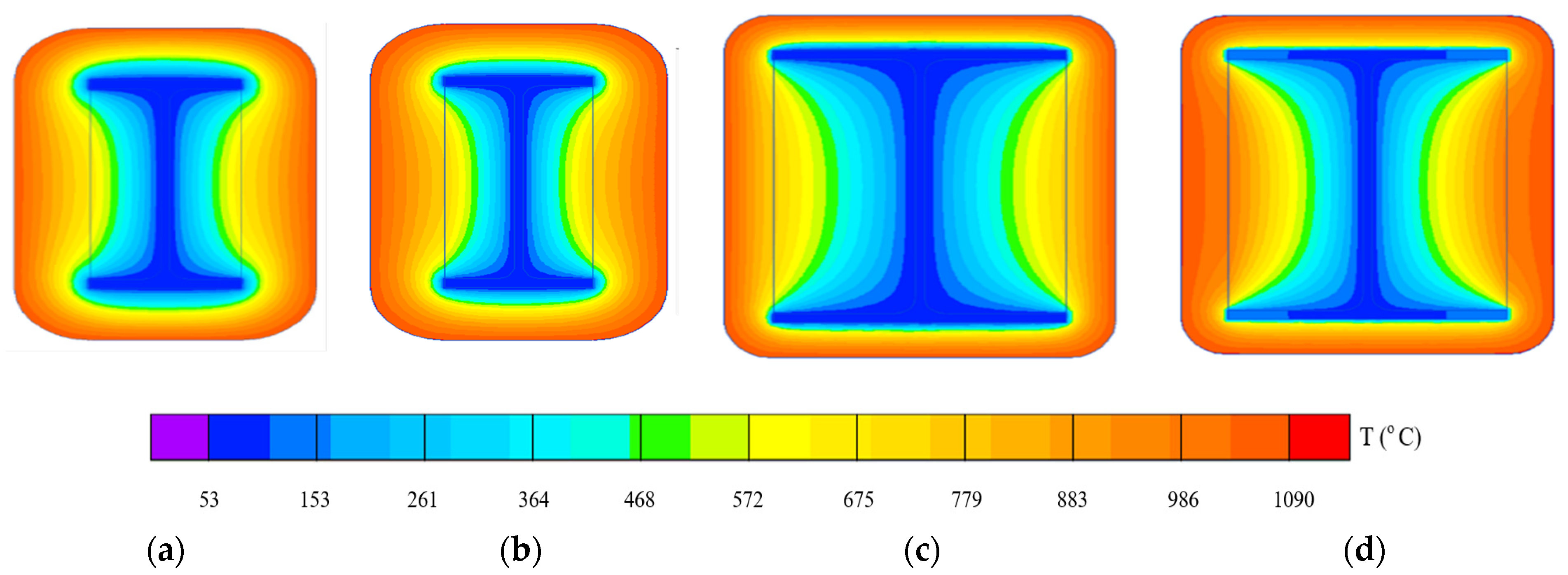
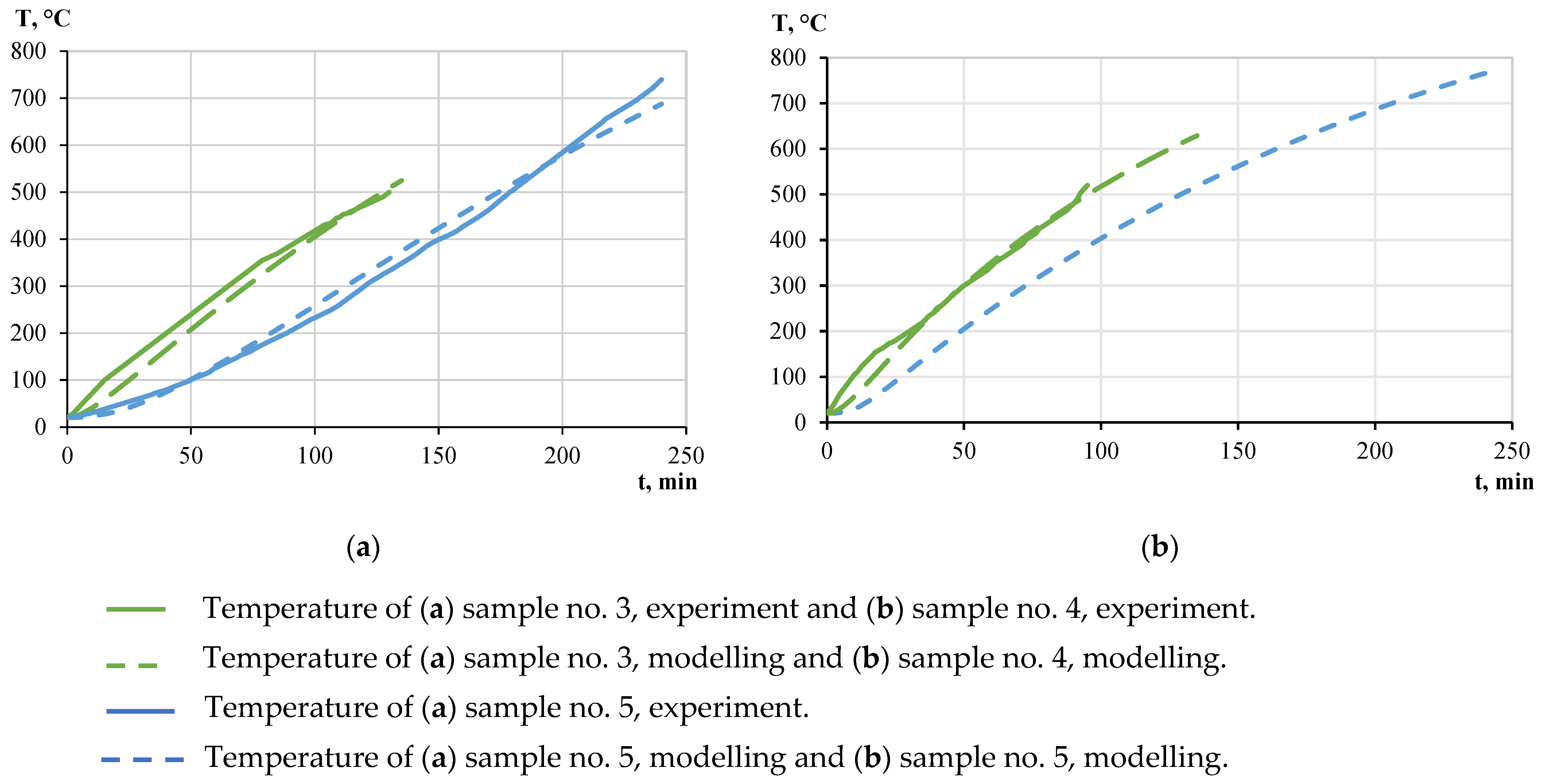
2.2.2. Simulation in SP QuickField 7.0
- -
- Equation of heat conduction:
- -
- Initial condition:
- -
- Boundary condition on the surface of the inverse heat conduction task at x = dp:
- -
- Boundary condition on the inner surface of the fireproof coating at x = 0:where
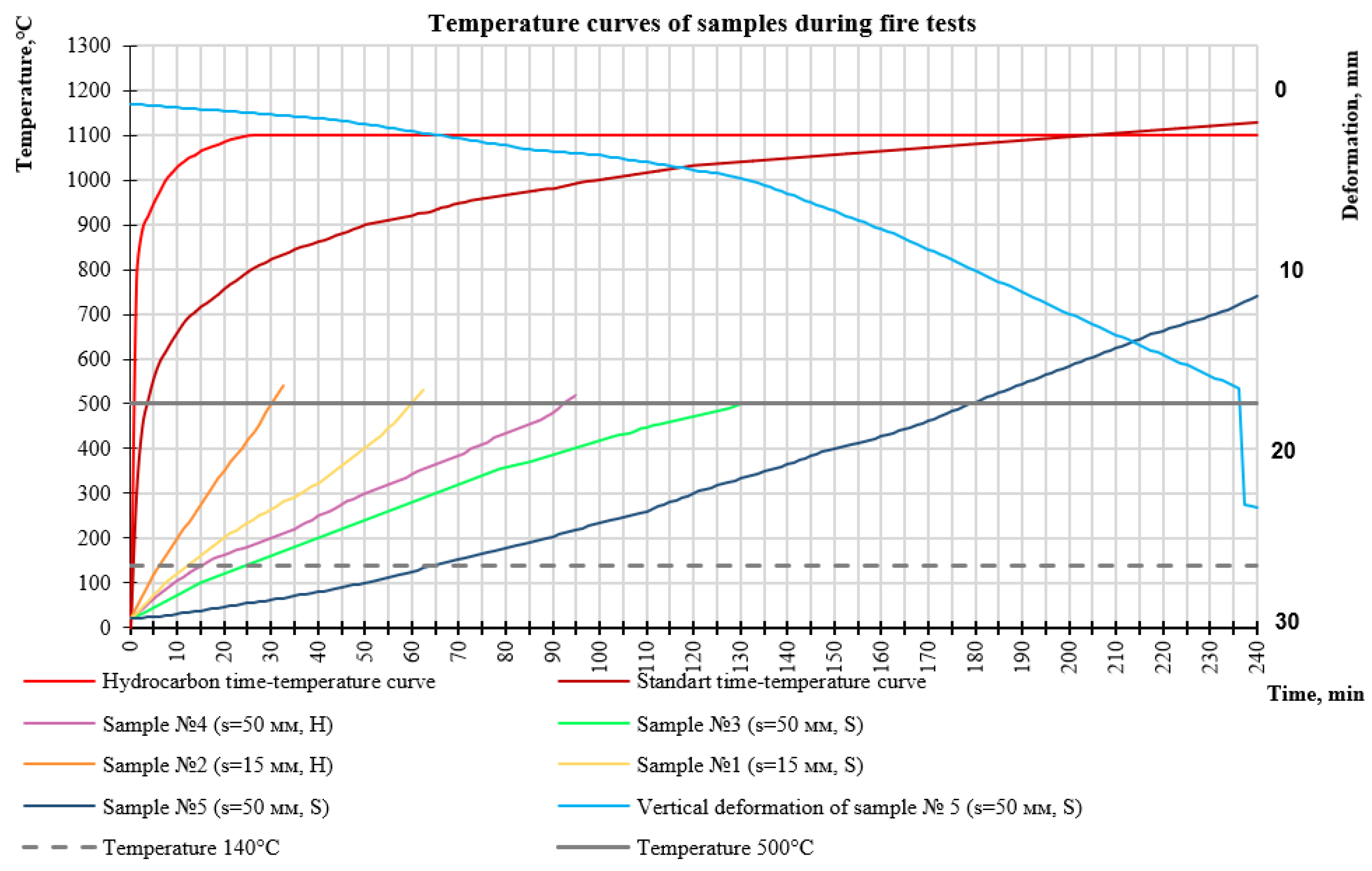
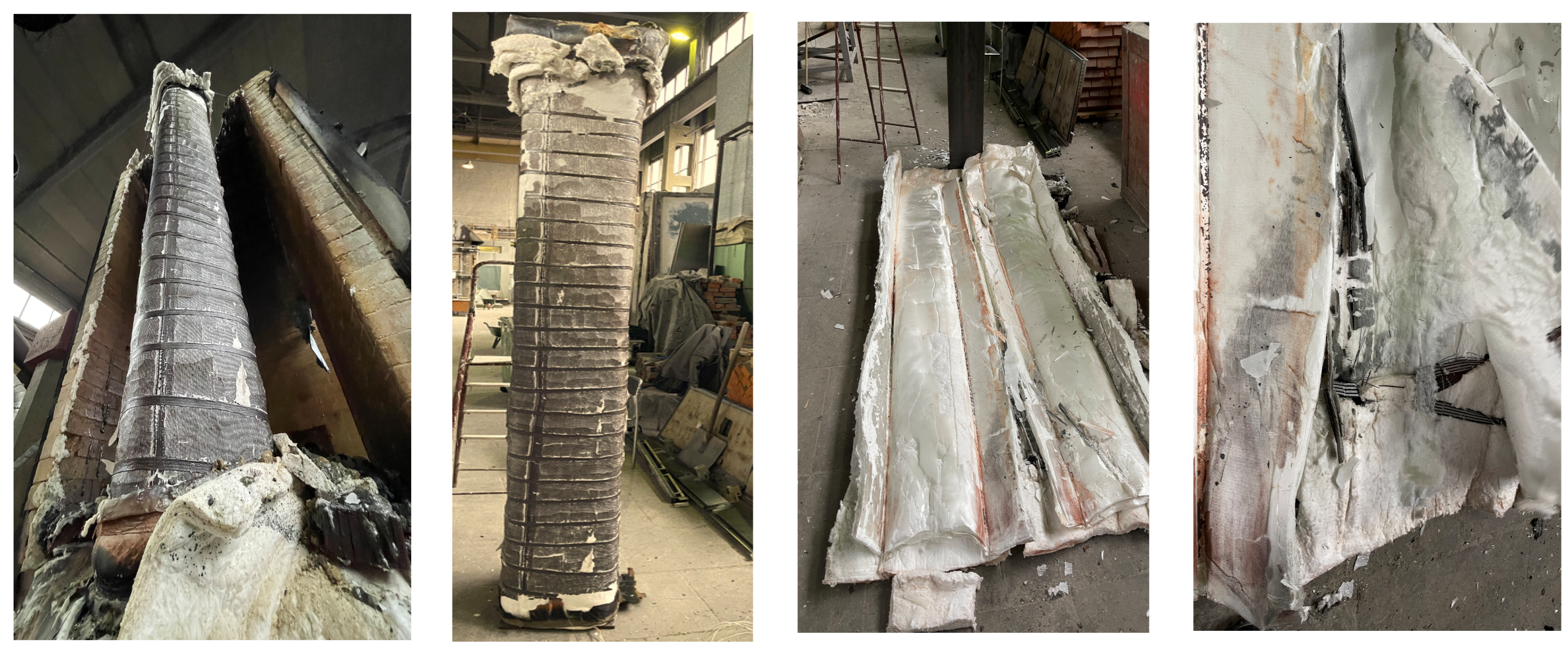
3. Results
4. Conclusions
5. Patents
Author Contributions
Funding
Institutional Review Board Statement
Informed Consent Statement
Data Availability Statement
Conflicts of Interest
References
- Imran, M.; Liew, M.s.; Nasif, M.S.; Niazi, M.U.K.; Yesreen, A. Hazard Assessment Studies on Hydrocarbon Fire and Blast: An Overview. J. Comput. Theor. Nanosci. 2017, 23, 1243–1247. [Google Scholar] [CrossRef]
- Kim, J.H.; Baeg, D.Y.; Seo, J.K. Numerical Investigation of Residual Strength of Steel Stiffened Panel Exposed to Hydrocarbon Fire. J. Ocean Eng. Technol. 2021, 35, 203–215. [Google Scholar] [CrossRef]
- Gravit, M.; Golub, E.; Klementev, B.; Dmitriev, I. Fire protective glass fiber reinforced concrete plates for steel structures under different types of fire exposure. Buildings 2021, 11, 187. [Google Scholar] [CrossRef]
- Shallcross, D.C. Using concept maps to assess learning of safety case studies—The Piper Alpha disaster. Educ. Chem. Eng. 2013, 8, e1–e11. [Google Scholar] [CrossRef]
- Zybina, O.; Gravit, M. Intumescent Coatings for Fire Protection of Building Structures and Materials; Springer Series on Polymer and Composite Materials; Springer International Publishing: Cham, Switzerland, 2020. [Google Scholar]
- Akporjevwe, U.G. The Piper Alpha Disaster—Impacts to Safety. Available online: https://www.researchgate.net/publication/349278316_The_Piper_Alpha_Disaster-_Impacts_to_Safety (accessed on 24 January 2024).
- Chen, D.; Werder, E.J.; Stewart, P.A.; Stenzel, M.R.; Gerr, F.E.; Lawrence, K.G.; Groth, C.P.; Huynh, T.B.; Ramachandran, G.; Banerjee, S.; et al. Exposure to volatile hydrocarbons and neurologic function among oil spill workers up to 6 years after the Deepwater Horizon disaster. Environ. Res. 2023, 231, 116069. [Google Scholar] [CrossRef]
- McClain, C.R.; Nunnally, C.; Benfield, M.C. Persistent and substantial impacts of the Deepwater Horizon oil spill on deep-sea megafauna. R. Soc. Open Sci. 2019, 6, 191164. [Google Scholar] [CrossRef]
- Evangelista, H.; Sodré, E.D.; Lima, A.C.M.e. Preliminary Investigation on the Atmospheric Dispersion of Pollutants Due to Ferraz Fire. INCT-APA Annu. Act. Rep. 2013, 35–42. [Google Scholar] [CrossRef]
- Pongpiachan, S.; Hattayanone, M.; Pinyakong, O.; Viyakarn, V.; Chavanich, S.A.; Bo, C.; Khumsup, C.; Kittikoon, I.; Hirunyatrakul, P. Quantitative ecological risk assessment of inhabitants exposed to polycyclic aromatic hydrocarbons in terrestrial soils of King George Island, Antarctica. Polar Sci. 2017, 11, 19–29. [Google Scholar] [CrossRef]
- Gravit, M.; Gumerova, E.; Bardin, A.; Lukinov, V. Increase of Fire Resistance Limits of Building Structures of Oil-and-Gas Complex Under Hydrocarbon Fire. Adv. Intell. Syst. Comput. 2018, 692, 818–829. [Google Scholar] [CrossRef]
- Eremina, T.; Korolchenko, D. Fire Protection of Building Constructions with the Use of Fire-Retardant Intumescent Compositions. Building 2020, 10, 185. [Google Scholar] [CrossRef]
- Kandola, B.K.; Luangtriratana, P.; Duquesne, S.; Bourbigot, S. The Effects of Thermophysical Properties and Environmental Conditions on Fire Performance of Intumescent Coatings on Glass Fibre-Reinforced Epoxy Composites. Materials 2015, 8, 5216–5237. [Google Scholar] [CrossRef]
- Jimenez, M.; Bellayer, S.; Revel, B.; Duquesne, S.; Bourbigot, S. Comprehensive Study of the Influence of Different Aging Scenarios on the Fire Protective Behavior of an Epoxy Based Intumescent Coating. Ind. Eng. Chem. Res. 2013, 52, 729–743. [Google Scholar] [CrossRef]
- Morys, M.; Häßler, D.; Krüger, S.; Schartel, B.; Hothan, S. Beyond the standard time-temperature curve: Assessment of intumescent coatings under standard and deviant temperature curves. Fire Saf. J. 2020, 112, 102951. [Google Scholar] [CrossRef]
- Chen, Y.; Jiang, M.; Shan, Y.; Yin, W.; Liu, X.; Hu, L.; Li, P.; Liu, J.; Zhang, C. Plastering Gypsum Construction Method of Steel Structure Wall Face With Anti-Corrosion Coating, and Fireproof Protection Device of Steel Structure Components. CN 110130533 A, 16 August 2019. [Google Scholar]
- Elbasuney, S.; Maraden, A. Novel Thermoset Nanocomposite Intumescent Coating Based on Hydroxyapatite Nanoplates for Fireproofing of Steel Structures. J. Inorg. Organomet. Polym. Mater. 2020, 30, 820–830. [Google Scholar] [CrossRef]
- Mahmud, H.M.I.; Mandal, A.; Nag, S.; Moinuddin, K.A.M. Performance of fire protective coatings on structural steel member exposed to high temperature. J. Struct. Fire Eng. 2021, 12, 193–211. [Google Scholar] [CrossRef]
- Jiang, S.; Wu, H. An Experimental Investigation on the Fire Resistance of the Integrated Envelope-Fire Protection Material for Steel Buildings. Prog. Steel Build. Struct. 2021, 23, 77–84. [Google Scholar] [CrossRef]
- Gravit, M.; Shabunina, D.; Shcheglov, N. Thermal Characteristics of Epoxy Fire-Retardant Coatings under Different Fire Regimes. Fire 2023, 6, 420. [Google Scholar] [CrossRef]
- SP 131.13330.2020 Building Climatology. Available online: https://docs.cntd.ru/document/573659358 (accessed on 29 January 2024).
- Kottek, M.; Grieser, J.; Beck, C.; Rudolf, B.; Rubel, F. World Map of the Köppen-Geiger climate classification updated. Meteorol. Zeitschrift 2006, 15, 259–263. [Google Scholar] [CrossRef]
- Abramov, I.V.; Gravit, M.V.; Gumerova, E.I. Increase in the fire resistance limits of ship and building structures with hydrocarbon fire. GAS Ind. 2018, 768, 108–117. [Google Scholar]
- Palazzi, E.; Fabiano, B. Analytical modelling of hydrocarbon pool fires: Conservative evaluation of flame temperature and thermal power. Process Saf. Environ. Prot. 2012, 90, 121–128. [Google Scholar] [CrossRef]
- Li, J.; Hao, H. Internal and external pressure prediction of vented gas explosion in large rooms by using analytical and CFD methods. J. Loss Prev. Process Ind. 2017, 49, 367–381. [Google Scholar] [CrossRef]
- Hassel, M.; Utne, I.B.; Vinnem, J.E. Allision risk analysis of offshore petroleum installations on the Norwegian Continental Shelf—An empirical study of vessel traffic patterns. WMU J. Marit. Aff. 2017, 16, 175–195. [Google Scholar] [CrossRef]
- Prusakov, V.A.; Gravit, M.V.; Simonenko, Y.B. Superthin Basalt Fiber as the Base of a Matrix of the Fire-Resistant Filling of Deformation Joints in Building Structures. Glas. Phys. Chem. 2023, 49, 75–80. [Google Scholar] [CrossRef]
- Al-Jadiri, M.S.F.; Said, A.M.I. Reinforced Concrete Columns Insulated by Different Gypsum Layers Exposed to 900 °C One Side Fire Flame. Eng. Technol. Appl. Sci. Res. 2023, 13, 11586–11592. [Google Scholar] [CrossRef]
- Batiz. Comparative Characteristics of Thermal Insulation Wool Obtained from Various Raw Materials. Available online: http://batis.ru/kompaniya/eto-interesno/30-sravnitelnaya-kharakteristika-teploizolyatsionnoj-vaty-poluchennoj-iz-razlichnogo-syrya/ (accessed on 24 January 2024).
- Budykina, T.; Anosova, Y. Thermal resistance of fire retardant materials. Mag. Civ. Eng. 2022, 112, 11213. [Google Scholar] [CrossRef]
- Pang, Y.; Zhong, Z.; Liu, H.; Rao, L. Research on Fire-Resistant Fabric Properties of Basalt Fiber. Appl. Mech. Mater. 2012, 217–219, 1151–1154. [Google Scholar] [CrossRef]
- Wang, K.; Fu, C.; Xu, A.; Wu, M.; Jia, L.; Xu, W.; Su, B.; Xia, Z. Skin-friendly and highly fireproof fabric up to 1142 °C weaved by basalt @ polyimide yarns. Compos. Part B Eng. 2022, 246, 110238. [Google Scholar] [CrossRef]
- Ming, H. Fire-Proof Basalt Fiber Cloth. CN 105088794 A, 25 November 2015. [Google Scholar]
- Xiang, W.; Maolin, L.; Xiaolong, T. Multi-Functional Basalt Fiber Fire Blanket. CN 207768955 U, 28 August 2018. [Google Scholar]
- Bezas, M.Z.; Nikolaidis, T.N.; Baniotopoulos, C.C. Fire Protection and Sustainability of Structural Steel Buildings with Double-Shell Brickwork Cladding. Procedia Environ. Sci. 2017, 38, 298–305. [Google Scholar] [CrossRef]
- Mahmood, E.M.; Allawi, A.A.; El-Zohairy, A. Analysis and Residual Behavior of Encased Pultruded GFRP I-Beam under Fire Loading. Sustainability 2022, 14, 13337. [Google Scholar] [CrossRef]
- Mahmood, E.M.; Ibrahim, T.H.; Allawi, A.A.; El-Zohairy, A. Experimental and Numerical Behavior of Encased Pultruded GFRP Beams under Elevated and Ambient Temperatures. Fire 2023, 6, 212. [Google Scholar] [CrossRef]
- Sotoodeh, K. Valve operability during a fire. J. Offshore Mech. Arct. Eng. 2019, 141, 044001. [Google Scholar] [CrossRef]
- Rezayiye, R.K.; Laurent, K.; Nooralishahi, P.; Ibarra-Castanedo, C.; Maldague, X. Thermal Data Augmentation Approach for the Detection of Corrosion in Pipes Using Deep Learning and Finite Element Modelling. Eng. Proc. 2023, 51, 20. [Google Scholar] [CrossRef]
- Shammazov, I.; Karyakina, E. The LNG Flow Simulation in Stationary Conditions through a Pipeline with Various Types of Insulating Coating. Nurse Res. 2023, 8, 68. [Google Scholar] [CrossRef]
- Home—Promizol. Available online: http://tdpromizol.com/home/ (accessed on 2 March 2024).
- PAO NOVATEK Business: Project Arctic LNG 2|Arctic LNG 2. Available online: https://www.novatek.ru/en/business/arctic-lng/ (accessed on 2 March 2024).
- ASTM E119; Standard Test Methods for Fire Tests of Building Construction and Materials. ASTM International: West Conshohocken, PA, USA, 2022. Available online: https://www.astm.org/e0119-00a.html (accessed on 29 January 2024).
- UL 1709-2017; Standard for Safety Rapid Rise Fire Tests of Protection Materials for Structural Steel. Underwriters Laboratories Inc. (UL): Northbrook, IL, USA, 2017. Available online: https://docs.cntd.ru/document/550713257 (accessed on 29 January 2024).
- Vorobev, N.N.; Barinov, D.Y.; Zuev, A.V.; Pakhomkin, S.I. Computational and experimental study of the effective thermal conductivity of fibrous materials. Proc. VIAM 2021, 7, 95–102. [Google Scholar] [CrossRef]
- Sound Insulation, Thermal Insulation and Refractory Materials|MIC-Izol. Available online: https://mikizol.ru/ (accessed on 24 January 2024).
- Prusakov, V.A.; Gravit, M.V.; Antonov, S.P. Fire-Resistant Multilayer Article for Fire Protection of Building Structures. RU2725720C1, 3 July 2020. [Google Scholar]
- GOST 53295-2009; Russian State Standard, Fire Retardant Compositions for Steel Constructions. General Requirement. Method for Determining Fire Retardant Efficiency. Standartinform Publ.: Moscow, Russia, 2009. Available online: https://docs.cntd.ru/document/1200071913 (accessed on 29 January 2024).
- GOST 26020-83; Russian State Standard, Hot-rolled Steel I-Beam with Parallel Flange Edges. Dimensions. IPK Izdatelstvo Standartov: Moscow, Russia, 2003. Available online: https://internet-law.ru/gosts/gost/21141/ (accessed on 29 January 2024).
- Eurocode 3: Design of Steel Structures; CEN (European Committee for Standardization): Brussels, Belgium, 2011; pp. 1–78.
- GOST 30247.1-94; Russian State Standard, Elements of Building Constructions. Fire-Resistance Test Methods. Loadbearing and Separating Constructions. IPK Izdatelstvo Standartov: Moscow, Russia, 1995. Available online: https://docs.cntd.ru/document/9055247 (accessed on 24 January 2024).
- GOST 30247.0-94; Russian State Standard, Elements of Building Constructions. Fire-resistance Test Methods. General Requirements. IPK Izdatelstvo Standartov: Moscow, Russia, 2003. Available online: https://docs.cntd.ru/document/9055248 (accessed on 29 January 2024).
- EN 1363-2:1999; Fire Resistance Tests—Part 2: Alternative and Additional Procedures. CEN (European Committee for Standardization): Brussels, Belgium, 2001.
- QuickField Support Site. Available online: https://quickfield.com/ (accessed on 29 January 2024).
- Gravit, M.; Shabunina, D.; Nedryshkin, O. The Fire Resistance of Transformable Barriers: Influence of the Large-Scale Factor. Fire 2023, 6, 294. [Google Scholar] [CrossRef]
- Gravit, M.; Shabunina, D. Numerical and Experimental Analysis of Fire Resistance for Steel Structures of Ships and Offshore Platforms. Fire 2022, 5, 9. [Google Scholar] [CrossRef]
- Wang, J.X.; Liu, K.; Zhao, C.S.; Wang, Z.L. Research on the theoretical calculation method of dynamic response of the stiffened plate on the accommodation of offshore platforms under blast. Chuan Bo Li Xue/J. Sh. Mech. 2020, 24, 1495–1506. [Google Scholar] [CrossRef]
- Kim, T.K.; Kim, S.K.; Lee, J.M. Dynamic Response of Drill Floor Considering Propagation of Blast Pressure Subsequent to Blowout. Appl. Sci. 2020, 10, 8841. [Google Scholar] [CrossRef]
- Kung, F.; Yang, M.C. Improvement of the Heat-Dissipating Performance of Powder Coating with Graphene. Polymer 2020, 12, 1321. [Google Scholar] [CrossRef]
- GOST 27772-2015; Russian State Standard, Rolled Products for Structural Steel Constructions. General Specifications. Standartinform Publ.: Moscow, Russia, 2016. Available online: https://docs.cntd.ru/document/1200133727 (accessed on 29 January 2024).
- EN 1991-1-2; Eurocode 1: Actions on Structures—Part 1–2: General Actions—Actions on Structures Exposed to Fire. CEN (European Committee for Standardization): Brussels, Belgium, 2002.
- Markus, E.S.; Snegirev, A.Y.; Kuznetsov, E.A. Numerical Simulation of a Fire Using Fire Dynamics; St. Petersburg Polytech-Press: St. Petersburg, Russia, 2021. [Google Scholar]


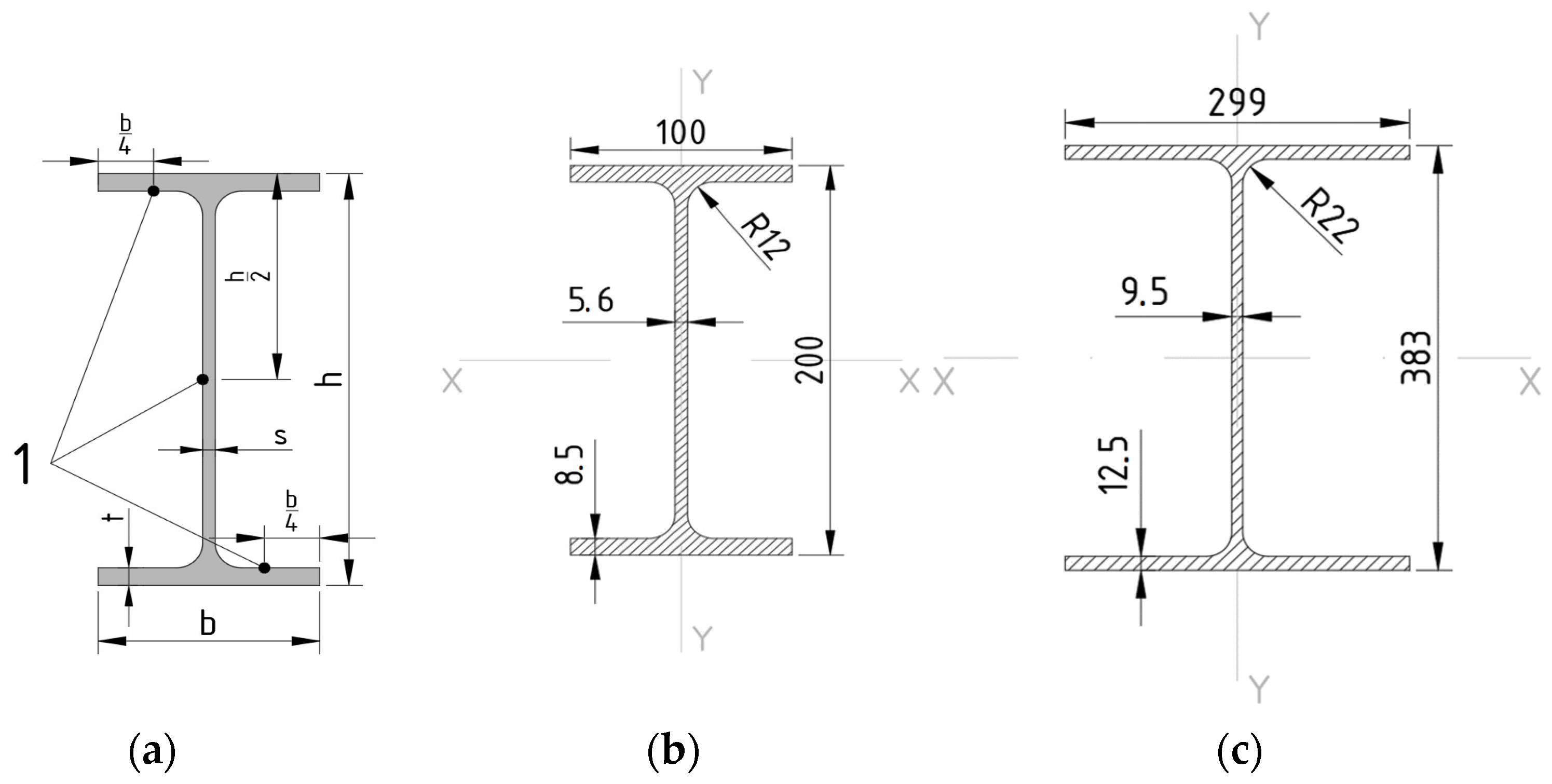
| Type | h, mm | b, mm | S, mm | t, mm | R, mm | F, cm2 | Ix, cm4 | Iy, cm4 |
|---|---|---|---|---|---|---|---|---|
| 20B1, sample nos. 1–4 | 200 | 100 | 5.6 | 8.5 | 12 | 28.49 | 1943 | 142.3 |
| IK40-beam, sample no. 5 | 383 | 299 | 9.5 | 12.5 | 22 | 112.91 | 30,556 | 5575.4 |
| Sample | Cross-Section | H, mm | Aρ/V, m−1 | Thickness, mm | Fire Regime | PE, min |
|---|---|---|---|---|---|---|
| Sample No. 1 | I20B1 | 1700 | 294 | 15 | S* | 60 |
| Sample No. 2 | I20B1 | 1700 | 294 | 15 | H | 30 |
| Sample No. 3 | I20 B1 | 1700 | 294 | 50 | S | 130 |
| Sample No. 4 | I20B1 | 1700 | 294 | 50 | H | 93 |
| Sample No. 5 | I40-beam/19.9 tf | 2700 | 134 | 50 | S | 243/180 ** |
| Name of the Value | Value | Information Source |
|---|---|---|
| Convection heat transfer coefficient with hydrocarbon temperature regime, W/(m2K) | 50 | [61] |
| Convection heat transfer coefficient with standard temperature regime, W/(m2K) | 25 | [61] |
| Surface absorption coefficient | 0.5 | [62] |
| Initial ambient temperature, °C | 20 | - |
| Density of the thermal insulation cover, kg/m3 | 125 | - |
| T, °C | 20 | 100 | 200 | 300 | 400 | 500 | 600 | 700 | 800 | 900 | 1000 | 1200 |
|---|---|---|---|---|---|---|---|---|---|---|---|---|
| λ, W/K·m | 0.17 | 0.07 | 0.04 | 0.04 | 0.06 | 0.10 | 0.15 | 0.21 | 0.29 | 0.36 | 0.44 | 0.60 |
| C, J/kg·m | 219 | 276 | 348 | 420 | 492 | 564 | 636 | 708 | 780 | 852 | 924 | 1069 |
Disclaimer/Publisher’s Note: The statements, opinions and data contained in all publications are solely those of the individual author(s) and contributor(s) and not of MDPI and/or the editor(s). MDPI and/or the editor(s) disclaim responsibility for any injury to people or property resulting from any ideas, methods, instructions or products referred to in the content. |
© 2024 by the authors. Licensee MDPI, Basel, Switzerland. This article is an open access article distributed under the terms and conditions of the Creative Commons Attribution (CC BY) license (https://creativecommons.org/licenses/by/4.0/).
Share and Cite
Gravit, M.; Prusakov, V.; Shcheglov, N.; Kotlyarskaya, I. Fire Protection of Steel Structures of Oil and Gas Facilities: Multilayer, Removable, Non-Combustible Covers. Fire 2024, 7, 86. https://doi.org/10.3390/fire7030086
Gravit M, Prusakov V, Shcheglov N, Kotlyarskaya I. Fire Protection of Steel Structures of Oil and Gas Facilities: Multilayer, Removable, Non-Combustible Covers. Fire. 2024; 7(3):86. https://doi.org/10.3390/fire7030086
Chicago/Turabian StyleGravit, Marina, Vasiliy Prusakov, Nikita Shcheglov, and Irina Kotlyarskaya. 2024. "Fire Protection of Steel Structures of Oil and Gas Facilities: Multilayer, Removable, Non-Combustible Covers" Fire 7, no. 3: 86. https://doi.org/10.3390/fire7030086
APA StyleGravit, M., Prusakov, V., Shcheglov, N., & Kotlyarskaya, I. (2024). Fire Protection of Steel Structures of Oil and Gas Facilities: Multilayer, Removable, Non-Combustible Covers. Fire, 7(3), 86. https://doi.org/10.3390/fire7030086