Article

Activation Energy of Hydrogen–Methane Mixtures

by
Anastasia Moroshkina
1,*,
Alina Ponomareva
2,
Vladimir Mislavskii
1,
Evgeniy Sereshchenko
1,
Vladimir Gubernov
1,
Viatcheslav Bykov
3 and
Sergey Minaev
1
1
P.N. Lebedev Physical Institute of Russian Academy of Sciences, 53 Leninskii Prosp., Moscow 119991, Russia
2
The Center for Chemical Engineering, ITMO University, 49 Kronverksky Prosp., St. Petersburg 197101, Russia
3
Karlsruhe Institute of Technology, Institute of Technical Thermodynamics, Engelbert-Arnold-Strasse 4, Building 10.91, D-76131 Karlsruhe, Germany
*
Author to whom correspondence should be addressed.
Submission received: 18 December 2023 / Revised: 23 January 2024 / Accepted: 25 January 2024 / Published: 29 January 2024
(This article belongs to the Special Issue State-of-the-Art on Hydrogen Combustion)

Abstract

:
In this work, the overall activation energy of the combustion of lean hydrogen–methane–air mixtures (equivalence ratio φ = 0.7−1.0 and hydrogen fraction in methane α = 0 , 2, 4) is experimentally determined using thin-filament pyrometry of flames stabilised on a flat porous burner under normal conditions ( p = 1 bar, T = 20 °C). The experimental data are compared with numerical calculations within the detailed reaction mechanism GRI3.0 and both approaches confirm the linear correlation between mass flow rate and inverse flame temperature predicted in the theory. An analysis of the numerical and experimental data shows that, in the limit of lean hydrogen–methane–air mixtures, the activation energy approaches a constant value, which is not sensitive to the addition of hydrogen to methane. The mass flow rate for a freely propagating flame and, thus, the laminar burning velocity, are measured for mixtures with different hydrogen contents. This mass flow rate, scaled over the characteristic temperature dependence of the laminar burning velocity for a one-step reaction mechanism, is found and it can also be used in order to estimate the parameters of the overall reaction mechanisms. Such reaction mechanisms will find implementation in the numerical simulation of practical combustion devices with complex flows and geometries.

1. Introduction

Many investigations have recently been focused on the study of the fundamental characteristics of a methane–hydrogen–air flame (hythane–air flame), which provide the essential knowledge for the implementation of hydrogen-enriched methane as a fuel. There has been numerical analyses of models with detailed reaction mechanisms [1,2,3,4,5,6,7,8,9,10,11,12] and experimental investigations, mainly within the well-known setups of a combustion bomb [13,14,15,16,17,18,19,20,21], a counter flow [22,23,24,25,26], burner-stabilised flames [20,27,28,29,30,31,32,33,34], and other configurations [35,36]. In [3], it is concluded that hydrogen chemistry supports the combustion of methane, extending the operating limits of lean burners. Some authors also report that the addition of hydrogen induces an upstream shift of O, OH, H radicals [3,7,9,18,25], as well as methane and temperature distribution profiles [6,9,10,25]. This can cause earlier methane decomposition in hydrogen-doped flames. Similar conclusions are found in [37] based on molecular dynamics simulations.
Even though modern computational power gives the opportunities to undertake calculation within reduced and detailed reaction kinetics, the one-step reaction models are still of great interest in cases of complex reacting flows and geometries. In a number of papers, the parameters of one-step reaction models are selected so as to better describe the dependence of laminar burning velocity or the heat release rate on the parameters of a combustion system [38,39,40]. As shown in [39,40], these selected parameters also give accurate predictions of temperature and the distribution of major species. Moreover, one-step chemical kinetics has become a cornerstone of asymptotic analysis [41]. It can still be very useful and efficient in understanding and estimating critical combustion phenomena like, e.g., the problem of the detonation-to-deflagration transition, both at quantitative and qualitative levels [42]. Hence, a description of the properties of the premixed, non-premixed, and partially premixed combustion of hydrocarbon fuels could be successfully studied by using the values of the Arrhenius reaction kinetics parameters [43]. Various optimisation approaches aimed at finding the kinetic parameters are proposed in [44,45,46].
Numerical calculations within models with detailed reaction mechanisms are often employed to estimate the global one-step kinetic parameters. The approach to calculating the activation energy for hydrogen–air [47,48] and methane–air [49] mixtures is used as the logarithmic derivative of flame speed with respect to the burned temperature. Certainly, for such methods, it is preferable to measure some kinetic parameters directly in experiments. The activation energy is probably the most important one, although attempts to determine not only the activation energy but also the orders of reactions have been previously made [50]. The activation energies of hydrogen–air and methane–air mixtures can be estimated from the measurements of the dependence of the ignition delay time on the temperature of the mixture [51,52]. It is shown in [53] that the logarithm of the velocity of the fresh mixture discharging from a flat porous burner as a function of the reciprocal of the burned temperature is linear for different hydrocarbon fuels considered. The apparent activation energy is usually estimated by the slope angle and it is found to be a function of the mixture composition, as presented in [54].
As is known [46], there is ambiguity in the choice of the correlation factor and activation energy if only the optimisation procedure is employed. This means that the choices of the parameters of the Arrhenius one-step reaction must guarantee suitability with the real characteristics of the combustion wave propagation. Thus, it is very important to find a way to measure some of these parameters in experiments in order to be able to develop global reaction mechanisms for different fuels. In this work, the apparent activation energy and correlation factor for the lean hydrogen–methane–air mixtures are determined, which can be further used in the global kinetic models for these mixtures. Lean combustion is usually considered as a way to increase the efficiency and mitigate the ecological burden of the combustion of fossil fuels, while hydrogen–methane (hythane) is a promising fuel in the transition to hydrogen energy. Thus, the development of short and reliable kinetic models which can be used in the numerical engineering of combustion chambers is an important problem. The methodology firstly described in [53] is linked to models with a single global reaction, detailed reaction mechanisms, and direct experimental measurements with the aim of developing an approach that will allow the modelling of combustion processes with a low dimensional dynamical system.

2. Methodology for Determining the Activation Energy

This work is a continuation of the study presented in [55], where the activation energy of a methane–air mixture was measured. The main methods for determining the activation energy can be found there; only a brief description of them is given below. The basic idea in determining the activation energy is that, in [53,55,56,57], an analytical dependence of the mass flow rate of the fresh mixture on the flame burned temperature was obtained for the case of a flame stabilised on the surface of a flat porous burner. In dimensional quantities, this correlation can be written as follows:
M ˙ = A e x p E a 2 R T f ,
where M ˙ is the mass flow rate of the fresh mixture, E a is the overall activation energy, T f is the flame front temperature, and A is the correlation factor:
A = ρ u b e x p E a 2 R T b ,
where ρ —fresh mixture density, u b —laminar burning velocity, and T b —adiabatic flame temperature. The dependence (1) was initially heuristically obtained and later rigorously derived by using the asymptotic method in the model of a burner-stabilised combustion front with an infinitely thin reaction zone (large activation energy asymptotic). According to Equation (1), the natural logarithm of the mass flow rate of a fuel–air mixture discharged from the burner surface is a linear function of the inverse flame temperature. Indeed, (1) can be formally rewritten as
ln M ˙ = ln A E a 2 R T f .
Therefore, in order to find the values of both activation energy and correlation factor, it is necessary to measure the dependence of the mass flow rate of the mixture, M ˙ , on the flame front temperature, T f . The activation energy, E a , and correlation factor, A, can then be obtained from the slope and intersection point with the ordinate axis of the graph of the linear function: ln M ˙ ( 1 / ( 2 R T f ) ) , correspondingly. Note that the linearity of this dependence was also repeatedly confirmed in numerical simulations with detailed reaction mechanisms [55]. The experimental algorithm can be thus summarised as follows: for each mixture composition, given the mass flow rate of the mixture and the ambient conditions, the flame front temperature, T f , is determined by measuring the dependence of gas temperature, T, on the distance, x, from the surface of the burner. The temperature, T f , is then approximated as the maximum of T ( x ) . Applying this procedure for various values of M ˙ and fixed other parameters of the system, the data required to plot the dependency (3) are collected and E a and A are estimated. The whole procedure is repeated to obtain the values of the activation energy and correlation factor as functions of the mixture composition for different parameters of the fresh mixture.
The mixture parameters α and φ are defined as follows:
α = X H 2 X C H 4 , φ = F / A ( F / A ) s t ,
where X i is molar fraction of the reaction species, F / A is the fuel–air ratio, and ( F / A ) s t refers to the stoichiometric value of F / A . In this case, the global stoichiometric reaction is written as follows:
( C H 4 + α H 2 ) + ( 2 + α / 2 ) ( O 2 + 3.76 N 2 ) = ( α + 2 ) H 2 O + C O 2 + ( 2 + α / 2 ) 3.76 N 2
and the equivalence ratio of the fuel–air mixture is
φ = X C H 4 f + X H 2 f X O 2 f ( 2 + α / 2 ) ,
where the upper index, f, denotes the value of the molar fraction in the fresh mixture.
As shown in [55,57,58], the increase in the mass flow rate at certain fresh mixture compositions leads to flame blow-off at M ˙ = M ˙ c r . As M ˙ approaches the critical value, the burner-stabilised flame tends towards a freely propagating combustion wave. In this case, the flow rate of the fresh mixture becomes equal to the laminar combustion rate. Thus, by finding the flame blow-off boundary, it is possible to experimentally determine the burning velocity u b .
As a result of this study, E a , A , u b are determined for various mixture compositions characterised by the equivalence ratio, φ , and the ratio of the molar fractions of hydrogen to methane, α . The experimental and numerical methods are described in more detail below.

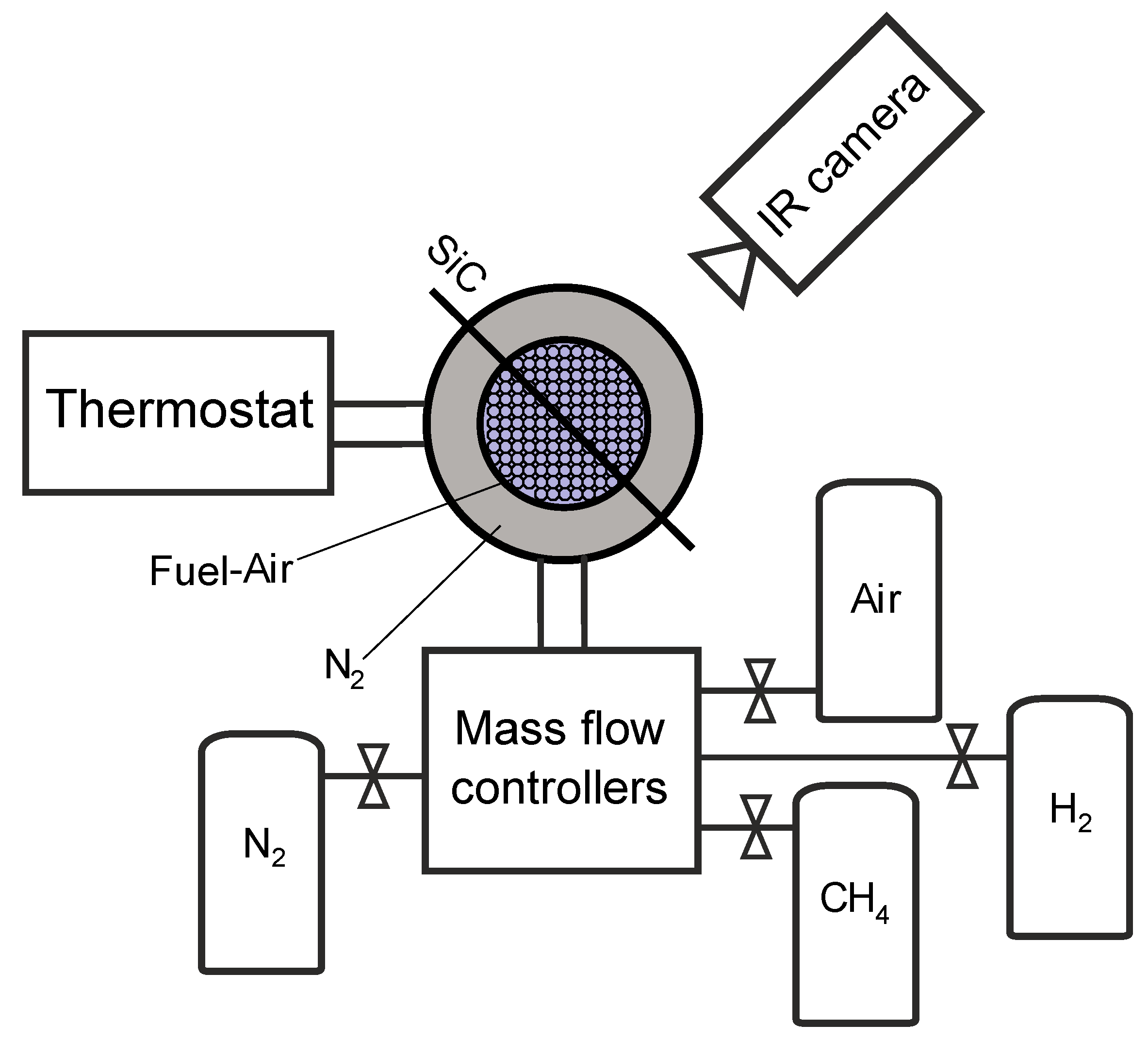
2.1. Experimental Setup

As described in [55], for a given fresh mixture composition ( φ , α ), the flame front temperature, T f , is measured for a set of mass flow rates, M ˙ , in a range between the critical values corresponding to the blow-off and the onset of pulsations arising due to the diffusive–thermal pulsating instabilities at sufficiently low flow rates when the flame approaches the burner surface. In this range, the flame is flat and stable. The thin-filament pyrometry method [59] was used to measure the flame temperature. In this work, radiation from a thin SiC filament (with diameter d 24 μ m and emissivity ε 0.84 ), which is placed parallel to the burner surface, is detected by an IR-camera OPTRIS PI 1M (Optris, Berlin, Germany) and the temperature of the filament is measured. Despite the invasiveness of this method, a SiC filament with such a small diameter does not significantly affect the structure of the stable flame. Due to heat losses, the filament temperature is lower than the gas temperature, which can be found according to the formula from [59]:
T g = T f i l a m e n t + ε σ h c T f i l a m n e t 4 ,
where σ —Stefan–Boltzmann constant and h c —heat exchange between the filament and the gas coefficient [55,60]. The value of the heat exchange coefficient can be found in [60] as h c = N u λ / d , where N u is the Nusselt number, d is the filament diameter, and λ is the thermal conductivity of the fuel mixture. Numerically, this correction can vary from about 50 K to 200 K in the temperature range of interest.
The experimental setup for measuring flame temperature is shown in Figure 1. It consists of a stainless steel flat porous burner with a diameter of a central part of 15 mm, through which the fresh methane–hydrogen–air mixture is supplied, a silicon carbide (SiC) filament, and an infrared camera. The central part of the burner is surrounded by a nitrogen co-flow channel to prevent air entrapment from the environment. The porous media consist of channels with a diameter of 0.2 mm and length of 40 mm and ensure the laminar flow of the fresh mixture. The burner is thermally stabilised using a thermostat (LOIP LT-205a, St. Petersburg, Russia) at T 0 = 20   ° C and equipped with a motorised linear translation stage (TS86-SMXZ Avesta, Moscow, Russia), which allows for changing the vertical position of the burner relative to the steadily fixed SiC filament with micron accuracy. To create a fuel–air mixture, CH4 and H2 were supplied from high pressure tanks with a gas purity of at least 99.99% through pressure reducers, while air was supplied from the compressor, into the burner fuel–air line through the mass flow controllers (Bronkhorst EL-FLOW Prestige, Ruurlo, The Netherlands). In each series of experiments, the ratio of hydrogen to methane was kept constant at α = 0, 2, 4. In turn, the ratio of hythane to air determined the equivalence ratio, which was also maintained constant using mass flow controllers. The mixture was prepared in a special chamber, which was located upstream of the burner. It is filled with porous media for better mixing, to which the methane, hydrogen, and air are supplied. As a result, only the total mixture flow rate, M ˙ , was changed for each mixture composition ( φ , α ) in every series of experiments. All measurements were carried out at normal pressure.
Since infrared cameras measure temperature differences with high accuracy (thermal sensitivity is less than 4 K), the IR-camera OPTRIS PI 1M was further calibrated according to the following procedure to obtain accurate data for measuring the absolute value of the filament temperature. For this purpose, the maximum mass flow rate of the fresh mixture while the flame was still flat ( M ˙ c r ) was determined. Blow-off occurs when the fresh mixture flow velocity becomes greater than the laminar flame velocity. As shown in [61], a flat combustion front cannot exist and it becomes corrugated as M ˙ passes over M ˙ c r . Finding the critical conditions for this transformation of flame morphology, along with thermal measurements, allows us to determine M ˙ c r and, for this mass flow rate, the flame burned temperature and fresh mixture flow velocity are equal to T b and u b , correspondingly. The adiabatic flame temperature, T b , is a thermodynamic quantity, which can be accurately calculated for the given mixture composition, α and φ . The IR-camera was calibrated assuming that the measured value of T f is equal to T b at M ˙ = M ˙ c r .

2.2. Modelling with the Detailed Reaction Mechanism

A numerical study of combustion processes in the investigated system was carried out using the open-source toolkit, Cantera [62]. Simulations were performed within the framework of the “burner-stabilised premixed flames” model for representing steady-state quasi-one-dimensional reacting flows using the detailed reaction mechanism, GRI3.0 [63]. The governing equations for a steady axisymmetric flow include the continuity equation and the conservation equations for momentum, energy, and species. A multicomponent diffusion model is used, which takes into account multicomponent and Soret diffusion coefficients. The ideal gas law and the quasi-uniform pressure assumption due to the low Mach number are used. It is assumed here that the burner surface is kept at a constant temperature T 0 = 20   ° C , which is controlled in experiments by the liquid thermal stabilisation system. Robin boundary conditions are applied for the species at the burner exit, which makes it possible to describe the flow of the fuel mixture with a given flow rate through the porous structure of the burner. The Neumann boundary conditions are implemented at the outlet boundary for all dependent variables. The size of the computational domain was 10 cm, which is significantly larger than the thermal thickness of the flame. As a result of calculations in the region of the investigated parameters, profiles of density, velocity, temperature, and species concentration distribution along the burner axis were obtained for all mixture compositions at given flow rates. From the data obtained, the dependence of the flame front temperature, T f , on the mixture flow rate, M ˙ , was determined, as well as the flow rate limit, M ˙ c r , at which the flame blows off from the burner and propagates as a free flame, was determined.

3. Results and Discussion

The IR-camera calibration procedure described above was undertaken for all mixture compositions studied here. This made it possible to obtain the values of the critical flow rates for flame blow-off. The dependencies of the measured values of M ˙ c r on φ for various values of the hydrogen fraction in methane, α = 0 , 2, and 4, are plotted in Figure 2 by circles, squares, and triangles, respectively. The figure shows error bars, except for the case α = 0, since the size of the bars is smaller than the markers. The data for the mass flow rate for the freely propagating flame, calculated with the detailed reaction mechanism GRI 3.0 for the same set of parameters, are shown with solid lines. The discrepancy between the experimental and numerical data is within the range of experimental errors, except point α = 4 , φ = 1 in Figure 2. This indicates that the measured value of M ˙ c r is an accurate approximation of the corresponding parameter of the freely propagating flame form, of which the laminar burning velocity can be easily found. Another important point is that the outlined calibration procedure guarantees that the experimental data for E a and A obtained in this way is automatically consistent with the dependence of M ˙ or u b on φ . In Figure 3, the data for the experimentally measured laminar flame speed u b is plotted versus the equivalence ratio for different values of hydrogen fraction in the fuel mixture α . A strong increase in flame velocity is observed with the addition of hydrogen to methane, as was predicted by other experimental studies known from the literature. In particular, the results from the papers [16,18,31,49] are also shown with empty circles and stars. There are quite big data compilations for laminar burning velocities for pure methane [61,64]. However, the data for hythane is scarce in comparison to this case α = 0 , for which rather good quantitative agreement between the current results and data from [49] can be seen in the figure. It can also be observed that the experimental data from various sources are more scattered for larger values of α . This reflects the need for more experimental data on the laminar burning velocity required to minimise this uncertainty to develop the ability for accurately predicting the behaviour of hythane–air flames in practical devices.
In Figure 4, the experimental data of the temperature dependence on the height above the burner Z for α = 2 , φ = 0.8 are shown with the circles connected with the solid line for several mass flow rates, M ˙ [kg/m2s]. The experimental errors in the figure are smaller than the symbols and are of the order of 5 °C. Such an accuracy is achieved by averaging over 1000 temperature measurements for every experimental point on the graphs. The range of variation in M ˙ is limited by the blow-off and the onset of oscillations [58]. The origin of the abscissa axis Z = 0 mm corresponds to an absolute height above the burner of the order of 200 μ m, which is the minimum position to which the filament can descend to the surface of the burner. This is due to the difficulties in directly approaching the surface of the burner with the SiC filament. Thus, the temperature does not approach T = 297 K at the left edge of the graphs T ( Z ) , which corresponds to the temperature of the fresh mixture. As can be seen from Figure 4, the temperature grows rapidly from the burner surface until it reaches a maximum, T f , and then becomes almost flat as Z is further increased. Relatively slow temperature decay is observed on significant distances from the burner due to heat losses and it is more noticeable for the cases of small M ˙ , such as 0.14 kg/m2s. From these thermograms, the maximum temperature values, T f , are determined as functions of the mass flow rates and the relationship is plotted according to Equation (1), as can be seen in Figure 5.
Figure 5 shows some typical graphs of ln ( M ˙ ) vs ( 1 / ( 2 R T f ) ) for α = 2 , φ = 0.8 and α = 4 , φ = 0.7 , and they can be well approximated by the linear dependencies. The slope of the graph is the overall activation energy for a certain mixture. Thus, the activation energy E a is determined as a function of the equivalence ratio φ by repeating this procedure for various mixture compositions, which is shown in Figure 6a. The errors are calculated on the basis that the temperature measurement error, after averaging by time and number of experiments, is less than 5 °C. The uncertainty of the mass flow rate is due to instrument and experimental error (in total, less than 5%). Uncertainties of activation energy are calculated as functions of Δ T and Δ M ˙ . Similarly to the experimental procedure for finding the activation energy, the numerical calculations were performed using the detailed reaction mechanism GRI 3.0, and are presented in Figure 6b. The numerical simulations predict that the activation energy approaches a constant value for lean mixture compositions regardless of the hydrogen content in the fuel. This suggests that experimental results within the range of experimental errors show that the value of activation energy is universal and equals 256 kJ/mol for all measured hydrogen–methane–air mixtures; the addition of hydrogen does not change this value in comparison with pure methane.
It can be assumed that the overall reaction rate W of the lean hythane–air mixture can be described using the following equation:
W = B [ F ] exp ( E a / R T ) ,
where [ F ] is molar fuel concentration, B = K [ O 2 ] , and K is the standard pre-exponential factor of the bimolecular reaction rate. In the limit of large activation energy, a well known expression for the laminar burning velocity can be employed in order to obtain the relation of B and A (see Equation (2)) as
B = A 2 β 2 2 ρ 2 L e ϰ ,
where β —Zeldovich number, ρ —the gas density, ϰ —thermal diffusivity, and L e —the Lewis number. This implies that coefficient A can also be used in order to approximate the kinetic parameters of the overall reaction mechanisms. Such an approach is employed, for example, in [65], to construct a two-step reaction mechanism of methane oxidation for the numerical simulation of a lean turbulent swirled premixed burner with constant activation energies of reaction steps and mixture-dependent correlation factors. In the case of more complex reaction mechanisms than the first order one-step reaction (4), parameter A can still be employed via Equation (2) once the dependence of u b on the system parameters is numerically or analytically calculated.
The value of A was estimated according to Equation (2), where ρ u b = M ˙ c r and E a were experimentally found. The results are shown in Figure 7 for three types of fuel mixtures. They are exactly the same as if A were found as the intersection of the approximation line with the vertical axis in Figure 5. Correlation factor uncertainties are estimated according to the procedure described above for activation energy. Error bars are not seen for the case of pure methane as they are smaller than the circles denoting the experimental data.

4. Conclusions

In this work, the overall activation energy of lean hydrogen–methane–air mixtures was determined on the basis of the thin-filament pyrometry of the flames stabilised at the flat porous burner. The experimental data were compared with the numerical calculations within the detailed reaction mechanism GRI 3.0. For both methods, the linear correlation between the mass flow rate and the inverse flame temperature was confirmed to be as earlier analytically predicted with the use of the one-step reaction model.
An analysis of the numerical and experimental data shows that, in the limit of lean hythane–air mixtures, the activation energy approaches a constant value, which is experimentally estimated to be equal to 256 kJ/mol. This differs from the numerical calculated value within 6 % . The value of the activation energy is not sensitive to the addition of hydrogen to methane, at least in the range of molar hydrogen fractions in the fuel studied here from 0 to 4. This indicates that there exists a common rate that limits the reaction step for both methane–air and hythane–air mixtures. In the future, we plan to study the reaction pathways and undertake sensitivity analyses within the detailed reaction mechanisms.
The parameter, A, which means the mass flow rate for a freely propagating flame, scaled over characteristic temperature dependence of the laminar burning velocity for a one-step reaction mechanism, is found as a function of the equivalence ratio and molar fraction of hydrogen in fuel. This dependence can also be used in order to estimate the parameters of the overall reaction mechanisms, which are described by the constant activation energy and various dependencies on the initial concentrations of the reactants. Such reaction mechanisms will find implementation in the numerical simulation of practical combustion devices with complex flows and geometries.
The calibration procedure of the experimental setup used here made it possible to measure the mass flow rate and laminar burning velocity of the freely propagating flame of lean hythane–air mixtures with different hydrogen contents. It is remarkable that the calibration also implies that, if the parameters A and E a found here are used to construct the overall one-step reaction mechanisms, as was discussed above, then it will provide the values of the laminar burning velocities measured in this work for the range of different mixture compositions. This can be very useful for future numerical modelling employing such mechanisms.
To summarise, the novelty and practical significance of the results obtained in this work is that the activation energy for hythane, which is considered today by many researchers as an important fuel in the transition to hydrogen energy, is measured for the first time for fuel mixtures with substantial fractions of hydrogen content. It was found that, in the limit of a lean flames, which is important in combustion applications, the activation energy approaches a constant value; this may be an indicator that a low dimensional gross reaction mechanism can be effectively constructed for predicting the behaviour of hythane combustion in various applications. The novel data for the activation energy, correlation factor, and laminar burning velocity of lean hythane–air combustion measured in the current work can be used in order to verify and develop the overall, reduced, and detailed reaction mechanisms required for the numerical simulations and design of practical combustion devices.

Author Contributions

Conceptualisation, V.G., V.B. and S.M.; methodology, V.G. and V.M.; software, E.S.; formal analysis, V.G. and S.M.; investigation, A.M., E.S. and A.P.; data curation, V.G., E.S., A.M. and A.P.; writing—original draft preparation, A.M., A.P., V.G. and E.S.; writing—review and editing, V.G., E.S. and V.B.; visualisation, A.M. and E.S.; supervision, V.B. All authors have read and agreed to the published version of the manuscript.

Funding

This work was supported by a grant from the Russian Science Foundation, RSF 21-13-00434.

Institutional Review Board Statement

Not applicable.

Informed Consent Statement

Not applicable.

Data Availability Statement

The data sets generated and/or analysed during the current study are available from the corresponding author on reasonable request.

Conflicts of Interest

The authors declare no conflicts of interest.

Nomenclature and Abbreviations

Nomenclature

p pressure
T temperature
T f  flame front temperature
T b  adiabatic flame temperature
T g  gas temperature

Abbreviations

ρ  density
R universal gas constant
E a  overall activation energy
A correlation factor
[ F ]  molar fuel concentration
K standard pre-exponential factor of the bimolecular reaction rate
u b  laminar burning velocity
M ˙ mass flow rate of the fresh mixture
M ˙ c r critical mass flow rate at which there is flame blow-off
φ equivalence ratio
α ratio of the molar fractions of hydrogen to methane
X i molar fraction of i-th species
Zheight above the burner
dfilament diameter
ε emissivity
σ Stefan–Boltzmann constant
h c heat exchange coefficient
λ thermal conductivity
ϰ thermal diffusivity
N u Nusselt number
β Zeldovich number
L e Lewis number

References

  1. Sher, E.; Refael, S. A simplified reaction scheme for the combustion of hydrogen enriched methane/air flame. Combust. Sci. Technol. 1988, 59, 371–389. [Google Scholar] [CrossRef]
  2. Refael, S.; Sher, E. Reaction kinetics of hydrogen-enriched methane-air and propane-air flames. Combust. Flame 1989, 78, 326–338. [Google Scholar] [CrossRef]
  3. Gauducheau, J.; Denet, B.; Searby, G. A numerical study of lean CH4/H2/air premixed flames at high pressure. Combust. Sci. Technol. 1998, 137, 81–99. [Google Scholar] [CrossRef]
  4. El-Sherif, S. Control of emissions by gaseous additives in methane—Air and carbon monoxide—Air flames. Fuel 2000, 79, 567–575. [Google Scholar] [CrossRef]
  5. Park, J.; Keel, S.I.; Yun, J.H. Addition effects of H2 and H2O on flame structure and pollutant emissions in methane–air diffusion flame. Energy Fuels 2007, 21, 3216–3224. [Google Scholar] [CrossRef]
  6. Wang, J.; Huang, Z.; Tang, C.; Miao, H.; Wang, X. Numerical study of the effect of hydrogen addition on methane—Air mixtures combustion. Int. J. Hydrogen Energy 2009, 34, 1084–1096. [Google Scholar] [CrossRef]
  7. Bougrine, S.; Richard, S.; Nicolle, A.; Veynante, D. Numerical study of laminar flame properties of diluted methane-hydrogen-air flames at high pressure and temperature using detailed chemistry. Int. J. Hydrogen Energy 2011, 36, 12035–12047. [Google Scholar] [CrossRef]
  8. Li, Q.; Hu, G.; Liao, S.; Cheng, Q.; Zhang, C.; Yuan, C. Kinetic effects of hydrogen addition on the thermal characteristics of methane—Air premixed flames. Energy Fuels 2014, 28, 4118–4129. [Google Scholar] [CrossRef]
  9. Ying, Y.; Liu, D. Detailed influences of chemical effects of hydrogen as fuel additive on methane flame. Int. J. Hydrogen Energy 2015, 40, 3777–3788. [Google Scholar] [CrossRef]
  10. Ren, F.; Chu, H.; Xiang, L.; Han, W.; Gu, M. Effect of hydrogen addition on the laminar premixed combustion characteristics the main components of natural gas. J. Energy Inst. 2019, 92, 1178–1190. [Google Scholar] [CrossRef]
  11. Liu, Y.; Zhang, J.; Ju, D.; Huang, Z.; Han, D. Analysis of exergy losses in laminar premixed flames of methane/hydrogen blends. Int. J. Hydrogen Energy 2019, 44, 24043–24053. [Google Scholar] [CrossRef]
  12. Xiang, L.; Jiang, H.; Ren, F.; Chu, H.; Wang, P. Numerical study of the physical and chemical effects of hydrogen addition on laminar premixed combustion characteristics of methane and ethane. Int. J. Hydrogen Energy 2020, 45, 20501–20514. [Google Scholar] [CrossRef]
  13. Law, C.K.; Kwon, O. Effects of hydrocarbon substitution on atmospheric hydrogen—Air flame propagation. Int. J. Hydrogen Energy 2004, 29, 867–879. [Google Scholar] [CrossRef]
  14. Halter, F.; Chauveau, C.; Djebaïli-Chaumeix, N.; Gökalp, I. Characterization of the effects of pressure and hydrogen concentration on laminar burning velocities of methane–hydrogen—Air mixtures. Proc. Combust. Inst. 2005, 30, 201–208. [Google Scholar] [CrossRef]
  15. Ilbas, M.; Crayford, A.; Yılmaz, I.; Bowen, P.; Syred, N. Laminar-burning velocities of hydrogen—Air and hydrogen—Methane—Air mixtures: An experimental study. Int. J. Hydrogen Energy 2006, 31, 1768–1779. [Google Scholar] [CrossRef]
  16. Huang, Z.; Zhang, Y.; Zeng, K.; Liu, B.; Wang, Q.; Jiang, D. Measurements of laminar burning velocities for natural gas—Hydrogen—Air mixtures. Combust. Flame 2006, 146, 302–311. [Google Scholar] [CrossRef]
  17. Halter, F.; Chauveau, C.; Gökalp, I. Characterization of the effects of hydrogen addition in premixed methane/air flames. Int. J. Hydrogen Energy 2007, 32, 2585–2592. [Google Scholar] [CrossRef]
  18. Hu, E.; Huang, Z.; He, J.; Jin, C.; Zheng, J. Experimental and numerical study on laminar burning characteristics of premixed methane—Hydrogen—Air flames. Int. J. Hydrogen Energy 2009, 34, 4876–4888. [Google Scholar] [CrossRef]
  19. Hu, E.; Huang, Z.; He, J.; Miao, H. Experimental and numerical study on lean premixed methane—Hydrogen—Air flames at elevated pressures and temperatures. Int. J. Hydrogen Energy 2009, 34, 6951–6960. [Google Scholar] [CrossRef]
  20. Eckart, S.; Pizzuti, L.; Fritsche, C.; Krause, H. Experimental study and proposed power correlation for laminar burning velocity of hydrogen-diluted methane with respect to pressure and temperature variation. Int. J. Hydrogen Energy 2022, 47, 6334–6348. [Google Scholar] [CrossRef]
  21. Yilmaz, H.; Schröder, L.; Hillenbrand, T.; Brüggemann, D. Effects of hydrogen addition on combustion and flame propagation characteristics of laser ignited methane/air mixtures. Int. J. Hydrogen Energy 2023, 48, 17324–17338. [Google Scholar] [CrossRef]
  22. Yu, G.; Law, C.; Wu, C. Laminar flame speeds of hydrocarbon + air mixtures with hydrogen addition. Combust. Flame 1986, 63, 339–347. [Google Scholar] [CrossRef]
  23. Ren, J.Y.; Qin, W.; Egolfopoulos, F.; Tsotsis, T. Strain-rate effects on hydrogen-enhanced lean premixed combustion. Combust. Flame 2001, 124, 717–720. [Google Scholar] [CrossRef]
  24. Ren, J.Y.; Qin, W.; Egolfopoulos, F.; Mak, H.; Tsotsis, T. Methane reforming and its potential effect on the efficiency and pollutant emissions of lean methane—Air combustion. Chem. Eng. Sci. 2001, 56, 1541–1549. [Google Scholar] [CrossRef]
  25. Jackson, G.S.; Sai, R.; Plaia, J.M.; Boggs, C.M.; Kiger, K.T. Influence of H2 on the response of lean premixed CH4 flames to high strained flows. Combust. Flame 2003, 132, 503–511. [Google Scholar] [CrossRef]
  26. Li, Z.; Cheng, X.; Wei, W.; Qiu, L.; Wu, H. Effects of hydrogen addition on laminar flame speeds of methane, ethane and propane: Experimental and numerical analysis. Int. J. Hydrogen Energy 2017, 42, 24055–24066. [Google Scholar] [CrossRef]
  27. Coppens, F.; De Ruyck, J.; Konnov, A.A. Effects of hydrogen enrichment on adiabatic burning velocity and NO formation in methane + air flames. Exp. Therm. Fluid Sci. 2007, 31, 437–444. [Google Scholar] [CrossRef]
  28. Coppens, F.; De Ruyck, J.; Konnov, A.A. The effects of composition on burning velocity and nitric oxide formation in laminar premixed flames of CH4 + H2 + O2 + N2. Combust. Flame 2007, 149, 409–417. [Google Scholar] [CrossRef]
  29. Konnov, A.; Riemeijer, R.; De Goey, L. Adiabatic laminar burning velocities of CH4 + H2 + air flames at low pressures. Fuel 2010, 89, 1392–1396. [Google Scholar] [CrossRef]
  30. Hermanns, R.; Konnov, A.A.; Bastiaans, R.; De Goey, L.; Lucka, K.; Köhne, H. Effects of temperature and composition on the laminar burning velocity of CH4 + H2 + O2 + N2 flames. Fuel 2010, 89, 114–121. [Google Scholar] [CrossRef]
  31. Dirrenberger, P.; Le Gall, H.; Bounaceur, R.; Herbinet, O.; Glaude, P.A.; Konnov, A.; Battin-Leclerc, F. Measurements of laminar flame velocity for components of natural gas. Energy Fuels 2011, 25, 3875–3884. [Google Scholar] [CrossRef]
  32. Zahedi, P.; Yousefi, K. Effects of pressure and carbon dioxide, hydrogen and nitrogen concentration on laminar burning velocities and NO formation of methane-air mixtures. J. Mech. Sci. Technol. 2014, 28, 377–386. [Google Scholar] [CrossRef]
  33. Nilsson, E.J.; van Sprang, A.; Larfeldt, J.; Konnov, A.A. The comparative and combined effects of hydrogen addition on the laminar burning velocities of methane and its blends with ethane and propane. Fuel 2017, 189, 369–376. [Google Scholar] [CrossRef]
  34. Volkov, D.; Moroshkina, A.; Mislavskii, V.; Sereshchenko, E.; Gubernov, V.; Bykov, V.; Minaev, S. Relaxational oscillations of burner-stabilized premixed methane—Air flames. Combust. Flame 2024, 259, 113141. [Google Scholar] [CrossRef]
  35. Scholte, T.; Vaags, P. Burning velocities of mixtures of hydrogen, carbon monoxide and methane with air. Combust. Flame 1959, 3, 511–524. [Google Scholar] [CrossRef]
  36. Lafay, Y.; Renou, B.; Cabot, G.; Boukhalfa, M. Experimental and numerical investigation of the effect of H2 enrichment on laminar methane—Air flame thickness. Combust. Flame 2008, 153, 540–561. [Google Scholar] [CrossRef]
  37. Liu, X.; Zhao, M.; Feng, M.; Zhu, Y. Study on mechanisms of methane/hydrogen blended combustion using reactive molecular dynamics simulation. Int. J. Hydrogen Energy 2023, 48, 1625–1635. [Google Scholar] [CrossRef]
  38. Westbrook, C.; Dryer, F. Simplified reaction mechanisms for the oxidation of hydrocarbon fuels in flames. Combust. Sci. Technol. 1981, 27, 31–43. [Google Scholar] [CrossRef]
  39. Coffee, T.; Kotlar, A.; Miller, M. The overall reaction concept in premixed, laminar, steady-state flames. I. Stoichiometries. Combust. Flame 1983, 54, 155–169. [Google Scholar] [CrossRef]
  40. Coffee, T.; Kotlar, A.; Miller, M. The overall reaction concept in premixed, laminar, steady-state flames. II. Initial temperatures and pressures. Combust. Flame 1984, 58, 59–67. [Google Scholar] [CrossRef]
  41. Barenblatt, G.; Librovich, V.; Makhviladze, G. The mathematical theory of combustion and explosions. In Consultants Bureau; Springer: Berlin/Heidelberg, Germany, 1985. [Google Scholar]
  42. Clavin, P. One-dimensional mechanism of gaseous deflagration-to-detonation transition. J. Fluid Mech. 2023, 974, A46. [Google Scholar] [CrossRef]
  43. Fernández-Tarrazo, E.; Sánchez, A.; Liñán, A.; Williams, F. A simple one-step chemistry model for partially premixed hydrocarbon combustion. Combust. Flame 2006, 147, 32–38. [Google Scholar] [CrossRef]
  44. Polifke, W.; Geng, W.; Döbbeling, K. Optimization of rate coefficients for simplified reaction mechanisms with genetic algorithms. Combust. Flame 1998, 113, 119–134. [Google Scholar] [CrossRef]
  45. Grenkin, G.; Chebotarev, A.; Babushok, V.; Minaev, S. Determination of global kinetic parameters by optimization procedure using burning velocity measurements. Math. Model. Nat. Phenom. 2018, 13, 50. [Google Scholar] [CrossRef]
  46. Zakharov, A.D.; Fursenko, R.V.; Minaev, S.S. Optimisation method for automatic selection of rate constants of global reaction mechanisms. Combust. Theory Model. 2022, 27, 153–167. [Google Scholar] [CrossRef]
  47. Christiansen, E.; Sung, C.; Law, C.K. Pulsating instability in near-limit propagation of rich hydrogen/air flames. Symp. (Int.) Combust. 1998, 27, 555–562. [Google Scholar] [CrossRef]
  48. Law, C.; Sung, C. Structure, aerodynamics, and geometry of premixed flamelets. Prog. Energy Combust. Sci. 2000, 26, 459–505. [Google Scholar] [CrossRef]
  49. Gu, X.J.; Haq, M.Z.; Lawes, M.; Woolley, R. Laminar burning velocity and Markstein lengths of methane–air mixtures. Combust. Flame 2000, 121, 41–58. [Google Scholar] [CrossRef]
  50. Vandenabeele, H.; Corbeels, R.; Van Tiggelen, A. Activation energy and reaction order inmethane-oxygen flames. Combust. Flame 1960, 4, 253–260. [Google Scholar] [CrossRef]
  51. Bane, S.; Ziegler, J.; Shepherd, J. Development of One-Step Chemistry Models for Flame and Ignition Simulation; GALCIT Report GALCITFM:2010.002; Graduate Aerospace Laboratories, California Institute of Technology: Pasadena, CA, USA, 2010; p. 53. [Google Scholar]
  52. Arutyunov, V.; Belyaev, A.; Arutyunov, A.; Troshin, K.; Nikitin, A. Autoignition of Methane–Hydrogen Mixtures below 1000 K. Processes 2022, 10, 2177. [Google Scholar] [CrossRef]
  53. Kaskan, W. The dependence of flame temperature on mass burning velocity. Symp. (Int.) Combust. 1957, 6, 134–143. [Google Scholar] [CrossRef]
  54. Francisco, R.W.; Oliveira, A.A.M. Simultaneous Measurement of the Adiabatic Flame Velocity and Overall Activation Energy using a Flat Flame Burner and a Flame Asymptotic Model. Exp. Therm. Fluid Sci. 2018, 90, 174–185. [Google Scholar] [CrossRef]
  55. Moroshkina, A.D.; Ponomareva, A.A.; Mislavskii, V.V.; Sereshchenko, E.V.; Gubernov, V.V.; Bykov, V.V.; Minaev, S.S. Determining the global activation energy of methane—Air premixed flames. Combust. Theory Model. 2023, 27, 909–924. [Google Scholar] [CrossRef]
  56. Ferguson, C.; Keck, J. Stand-off distances on a flat flame burner. Combust. Flame 1979, 34, 85–98. [Google Scholar] [CrossRef]
  57. Kurdyumov, V.; Matalon, M. The porous-plug burner: Flame stabilization, onset of oscillation, and restabilization. Combust. Flame 2008, 153, 105–118. [Google Scholar] [CrossRef]
  58. Moroshkina, A.; Mislavskii, V.; Kichatov, B.; Gubernov, V.; Bykov, V.; Maas, U. Burner stabilized flames: Towards reliable experiments and modelling of transient combustion. Fuel 2023, 332, 125754. [Google Scholar] [CrossRef]
  59. Vilimpoc, V.; Goss, L.; Sarka, B. Spatial temperature-profile measurements by the thin-filament-pyrometry technique. Opt. Lett. 1988, 13, 93–95. [Google Scholar] [CrossRef]
  60. Maun, J.D.; Sunderland, P.B.; Urban, D.L. Thin-filament pyrometry with a digital still camera. Appl. Opt. 2007, 46, 483–488. [Google Scholar] [CrossRef]
  61. Nechipurenko, S.; Miroshnichenko, T.; Pestovskii, N.; Tskhai, S.; Kichatov, B.; Gubernov, V.; Bykov, V.; Maas, U. Experimental observation of diffusive-thermal oscillations of burner stabilized methane-air flames. Combust. Flame 2020, 213, 202–210. [Google Scholar] [CrossRef]
  62. Goodwin, D.G. Cantera C++ User’s Guide; California Institute of Technology: Pasadena, CA, USA, 2002; Volume 32. [Google Scholar]
  63. Smith, G.; Golden, D.; Frenklach, M.; Moriarty, N.; Eiteneer, B.; Goldenberg, M.; Bowman, C.; Hanson, R.; Song, S.; Gardiner, W., Jr.; et al. GRI-Mech 3.0. 1999. Available online: http://combustion.berkeley.edu/gri-mech/ (accessed on 17 December 2023).
  64. Konnov, A.A.; Mohammad, A.; Kishore, V.R.; Kim, N.I.; Prathap, C.; Kumar, S. A comprehensive review of measurements and data analysis of laminar burning velocities for various fuel + air mixtures. Prog. Energy Combust. Sci. 2018, 68, 197–267. [Google Scholar] [CrossRef]
  65. Franzelli, B.; Riber, E.; Gicquel, L.Y.; Poinsot, T. Large eddy simulation of combustion instabilities in a lean partially premixed swirled flame. Combust. Flame 2012, 159, 621–637. [Google Scholar] [CrossRef]
Figure 1. Experimental setup.
Fire 07 00042 g001
Figure 2. The critical mass flow rate, M ˙ c r , as a function of the equivalence ratio, φ , for different values of α . Markers show the experimental data and the solid curves represent the numerical calculations.
Fire 07 00042 g002
Figure 3. The experimental dependence of the laminar flame speed U b on the equivalence ratio ϕ for α = 0 , 2, and 4, shown with the green, red, and blue squares, respectively. The results found in [16,18,31,49] are also plotted with the empty circles and stars, as described in the figure legend.
Fire 07 00042 g003
Figure 4. The experimental dependence of the temperature T [ K ] on the height above the burner Z for α = 2 , φ = 0.8 , and different mass flow rates M ˙ [kg/m2s].
Fire 07 00042 g004
Figure 5. The dependence of ln M ˙ on (− 1 / 2 R T f ) for α = 2 , φ = 0.8 and α = 4 , φ = 0.7 measured experimentally.
Fire 07 00042 g005
Figure 6. Overall activation energy as function of φ (a) experimental and (b) numerical with detailed reaction model GRI 3.0 for different hydrogen-to-methane ratios α , as shown in figure legend.
Fire 07 00042 g006
Figure 7. The dependence of correlation factor A on equivalence ratio for α = 0 , 2, 4 based on the experimental data.
Fire 07 00042 g007
Disclaimer/Publisher’s Note: The statements, opinions and data contained in all publications are solely those of the individual author(s) and contributor(s) and not of MDPI and/or the editor(s). MDPI and/or the editor(s) disclaim responsibility for any injury to people or property resulting from any ideas, methods, instructions or products referred to in the content.

