Article

Cooling Performance of a Nano Phase Change Material Emulsions-Based Liquid Cooling Battery Thermal Management System for High-Capacity Square Lithium-Ion Batteries

1
Naval University of Engineering, Wuhan 430030, China
2
Wuhan Second Institute of Ship Design and Research, Wuhan 430064, China
3
School of Safety Science and Emergency Management, Wuhan University of Technology, Wuhan 430070, China
*
Author to whom correspondence should be addressed.
Fire 2024, 7(10), 371; https://doi.org/10.3390/fire7100371
Submission received: 1 September 2024 / Revised: 23 September 2024 / Accepted: 28 September 2024 / Published: 18 October 2024
(This article belongs to the Special Issue Fire Safety of the New Emerging Energy)

Abstract

:
This study investigated the application of nanophase change material emulsions (NPCMEs) for thermal management in high-capacity ternary lithium-ion batteries. We formulated an NPCME of n-octadecane (n-OD) and n-eicosane (n-E) with a mass fraction of 10%, whose phase change temperatures are 25.5 °C and 32.5 °C, respectively, with specific heat capacities 2.1 and 2.4 times greater than water. Experiments were conducted to evaluate the thermal control performance and latent heat utilization efficiency of these NPCMEs. The NPCMEs with an n-OD mass fraction of 10% (NPCME-n-OD), particularly reduced the battery pack’s maximum temperature and temperature difference to 41.6 °C and 3.72 °C under a 2 C discharge rate, lower than the water-cooled group by 1.3 °C and 0.3 °C. This suggests that nano emulsions with phase change temperatures close to ambient temperatures exhibit superior cooling performance. Increased flow rates from 50 mL/min to 75 mL/min significantly lowered temperatures, resulting in temperature reductions of 2.73 °C for the NPCME-n-OD group and 3.37 °C for the NPCME-n-E group. However, the latent heat utilization efficiency of the nano emulsions decreased, leading to increased system energy consumption. Also, it was found that the inlet temperature of the NPCMEs was very important for good thermal management. The right inlet temperatures make it easier to use phase change latent heat, while excessively high temperatures may make thermal management less effective.

1. Introduction

Lithium-ion batteries are widely used in electric vehicles and energy storage systems due to their high energy density and long lifespan [1,2]. However, their performance, safety, and lifespan are significantly affected by operating temperature [3,4]. High temperatures can trigger internal side reactions, accelerating capacity decay and aging, and may even lead to thermal runaway and safety incidents [5]. Uneven temperature distributions within the battery pack can also cause inconsistencies in the electrochemical processes, reducing their capacity and lifespan [6]. Therefore, an efficient Battery Thermal Management System (BTMS) is crucial for ensuring the safety and performance of lithium-ion batteries in electric vehicles.
To date, a variety of BTMSs have been proposed, including air cooling [7,8,9], liquid cooling [10,11,12], phase change material (PCM) cooling [13,14], and heat pipe cooling [15]. PCM and heat pipes, as passive cooling technologies, are favored for their low maintenance costs and no additional energy consumption. However, PCMs are prone to leakage [16,17,18]; heat pipes, on the other hand, are overly dependent on the temperature difference between the two ends [19]. Air cooling technology, as one of the earliest commercialized thermal management methods, is favored due to its simple devices, convenient maintenance, and low cost [20]. However, in practical applications, to ensure heat dissipation, air cooling requires a large space and a high air flow rate, leading to a lower energy density of the system and high energy consumption, which limits its application in the modern commercial vehicle sector [21].
Compared to other cooling technologies, liquid cooling stands out for its compactness and high heat transfer coefficients, offering superior advantages in terms of energy density and temperature control performance for battery packs, making it the preferred choice in commercial vehicles [22,23]. Currently, commercial liquid cooling battery thermal management systems typically employ a design where the coolant flows through a heat exchanger in indirect contact with the batteries, providing effective heat dissipation while maintaining high energy density and safety performance. However, the coolants used in commercial liquid cooling systems are mostly water or glycol solutions [5,24], which have limited thermal conductivity and specific heat capacity, constraining the heat transfer efficiency between the fluid and the batteries. As battery capacity and heat generation density increase, liquid cooling systems require higher inlet flow rates to meet the enhanced cooling demands, significantly increasing the pump power consumption of the system. Therefore, it is necessary to develop new coolants with superior thermophysical properties to satisfy the cooling requirements under lower pump power consumption.
Phase change material emulsions (PCMEs), as a type of latent heat functional fluid, are prepared by dispersing phase change materials in a base liquid [25]. They not only possess fluidity but also inherit the physical heat storage characteristics of phase change materials, particularly exhibiting a higher specific heat capacity than water during the phase change process [26,27]. Consequently, PCME has the potential to serve as a novel coolant, replacing traditional water-based coolants, thereby enhancing the heat transfer between the liquid coolant and batteries and improving the temperature control performance of liquid cooling systems while also avoiding the risk of leakage associated with solid phase change materials. Based on particle size, PCMEs can be categorized into micrometric and nanometric emulsions [25]. Among these, nanophase change material emulsions (NPCMEs) have garnered more attention due to their improved dynamic stability, which is attributed to their resistance to phase separation and lower viscosity [28,29,30].
Xiang et al. [31] proposed a solution of a 20 wt% paraffin wax emulsion reinforced with graphene, and experimental results indicated that the incorporation of graphene significantly reduced the supercooling degree from 14.23 °C to 0.27 °C, with a latent heat variation of less than 86 J/g (3%), and enhanced the thermal conductivity by 20.22%. Zhang et al. [32] utilized octadecane as a phase change material, incorporated high thermal conductivity multi-walled carbon nanotubes (MWCNTs), and used octadecanol as a nucleating agent to prepare a nanoparticle phase change emulsion (NPCME) with low supercooling and high thermal conductivity. The results demonstrated that this nano emulsion exhibited good stability, minimal supercooling, and strong thermal conductivity. Zhang et al. [33] employed a composite surfactant system consisting of sodium dodecyl benzene sulfonate (SDBS), Sorbitan oleate (Span80), and polysorbate (Tween80), along with titanium dioxide nanoparticles as a nucleating agent, to prepare a highly stable and low-supercooling paraffin wax nano emulsion via ultrasonication. The emulsion maintained its stability without noticeable phase separation after 180 days of put and 200 thermal cycles. Additionally, the application of NPCMEs as coolants for the thermal management of electronic components has been explored by scholars. Wang et al. [34] pioneered the use of NPCME as a coolant in liquid cooling thermal management systems, preparing NPCMEs with an OP28E mass fractions of 10% and 20% using ultrasonication. Thermal management performance tests showed that both concentrations of OP28E NPCME outperformed water, with the 10 wt% OP28E NPCME reducing the maximum temperature (Tmax) and temperature difference (ΔT) to 45.5 °C and 3.3 °C, respectively, under a 2 C discharge rate, which were 1.1 °C and 0.8 °C lower than those of water. Cao et al. [35] proposed a 4 mm ultra-thin microchannel cooling system based on NPCME for high-rate discharge lithium-ion batteries. The results indicated that when the inlet temperature was below or close to the melting point, the cooling effect of NPCME was superior to that of water. At a 9 C flow rate, the Tmax and ΔT of the battery cooled with 10 wt% NPCME-OP44E were 46 °C and 3.5 °C, respectively, compared to 49.5 °C and 4.8 °C with water cooling. Mitra et al. [36] prepared nanofluids with three different volume fractions (0.15%, 0.3%, and 0.45%) of multi-walled carbon nanotubes (MWCNTs) and investigated the impact of coolant flow direction in single- and dual-channel liquid cooling on thermal management effectiveness. The findings revealed that at a 0.45% volume fraction of MWCNTs and a discharge rate of 2.1 C, the average temperature of the battery pack was reduced by 6.9 °C, 10.2 °C, and 11 °C under single-channel flow, dual-channel parallel flow, and dual-channel counterflow conditions, respectively.
It is evident that current research on NPCMEs is primarily focused on two aspects: one is the enhancement of material performance, including improving supercooling, thermal stability, and thermal conductivity; the other is the application of NPCMEs as coolants in lithium battery liquid cooling technology for thermal management, along with exploring their effectiveness and usage strategies when used as such. However, research on the application of NPCMEs in lithium battery liquid cooling systems for thermal management is relatively scarce, and it has mainly concentrated on cylindrical cells, lithium iron phosphate batteries, and batteries with lower heat generation. The cooling effects when applied to high heat-generating prismatic high-capacity batteries are not yet clear, and there is a lack of comprehensive analysis of factors affecting the cooling effects and the degree of latent heat utilization. This study constructed a liquid cooling thermal management system for lithium-ion batteries and applied it to large prismatic high-capacity lithium-ion batteries. The focus was on the cooling effects of two types of nano emulsions with phase change temperatures close to ambient temperature when used in battery thermal management, and an analysis of the degree of latent heat utilization. The study also explored various factors affecting cooling performance and latent heat utilization, including discharge rates, flow rates, and inlet temperatures. The aim was to provide new ideas and usage strategies for the application of NPCME as a novel coolant in liquid cooling systems for ternary batteries.

2. Experiment and Method

In this section, we describe the design of a liquid cooling thermal management system for lithium-ion batteries based on NPCMEs. First, we utilized n-OD and n-E as phase change materials and prepared two types of NPCMEs with distinct phase change temperatures using an ultrasonic emulsification method. We evaluated the particle size distribution of the NPCMEs and tested their phase change enthalpy and specific heat capacity to assess their thermophysical properties. Finally, these NPCMEs were employed as coolants in a battery thermal management system, and battery charging and discharging experiments under various conditions were conducted.

2.1. Preparation and Characterization of the NCPMEs

2.1.1. Preparation

The ultrasonic emulsification method [34] was employed to prepare an NPCME of n-octadecane (n-OD) and n-eicosane (n-E) at a mass fraction of 10% each. The procedure for preparing the 10 wt% n-octadecane NPCME (NPCME-n-OD) is outlined below. Initially, 30 g of n-OD is placed in a beaker and heated to 55 °C using a water bath. Subsequently, 3 g of docosane, serving as a nucleating agent, is introduced. The mixture is stirred magnetically at 55 °C for 10 min to achieve uniform mixing, yielding a solution of phase change material and nucleating agent. Then, 7.5 g of the surfactant sodium dodecyl sulfate is weighed and added to two 259.5 g of deionized water, which is stirred magnetically in a 50 °C water bath for ten minutes to obtain the surfactant aqueous solution. The uniformly mixed PCM and nucleating agent are added to the surfactant aqueous solution and stirred magnetically at 50 °C for 10 min. The mixed solution is subsequently subjected to an ultrasonic water bath for 30 min, followed by sonication with a 750 W ultrasonic disruptor for an additional 30 min, resulting in a nano emulsion with a PCM mass fraction of 10%.

2.1.2. Characterization

The particle size of the material was measured using a Zetasizer Nano system (Nano-ZS90, Malvern Instruments, Malvern, Worcestershire, UK) with a measurement range of 0.01 to 10,000 nm and an accuracy of less than ±1%. The specific testing procedure is as follows. First, a certain volume of distilled water is added to dilute the sample by 1000 times; then, the diluted sample is dropped into a quartz cuvette, and finally, the cuvette containing the sample is placed in the Zetasizer Nano system for particle size measurement. The measurement temperature of the sample is 25 °C, and each sample is tested three times.
The phase change temperature, enthalpy of phase change, and apparent specific heat capacity of the nano phase change emulsion were determined by differential scanning calorimetry (DSC, Q20, TA Instruments, New Castle, DE, USA). Then, 5–10 mg of the sample was weighed and placed in an Al 2 O 3 crucible, and a temperature program was performed under a nitrogen atmosphere of 50 mL/min at a heating and cooling rate of 5 °C/min, recording the curve of heat flow with temperature changes. To ensure complete melting and solidification of the test sample, the temperature range for the measurement was always 5–50 °C.

2.2. Liquid Cooling Battery Thermal Management System

The battery pack structure, as depicted in Figure 1a, consists of two series-connected square batteries and an intermediate cold plate. To minimize contact thermal resistance, thermally conductive silicone with a high thermal conductivity is filled between the cold plate and the batteries. The detailed structure of the cold plate is shown in Figure 1b,c; it measures 5.5 mm in thickness, 93 mm in height, and 148 mm in width, with internal channels of 2 mm diameter that are interconnected. The cooling fluid inlets and outlets are positioned at diagonally opposite sides, each fitted with a pagoda-shaped water nozzle of 3 mm outer diameter for connection to hoses. The batteries are square ternary lithium-ion batteries (INP58P) produced by Huizhou Eve Lithium Energy Co., Ltd. (Huizhou, China), and their specific parameters are listed in Table 1.
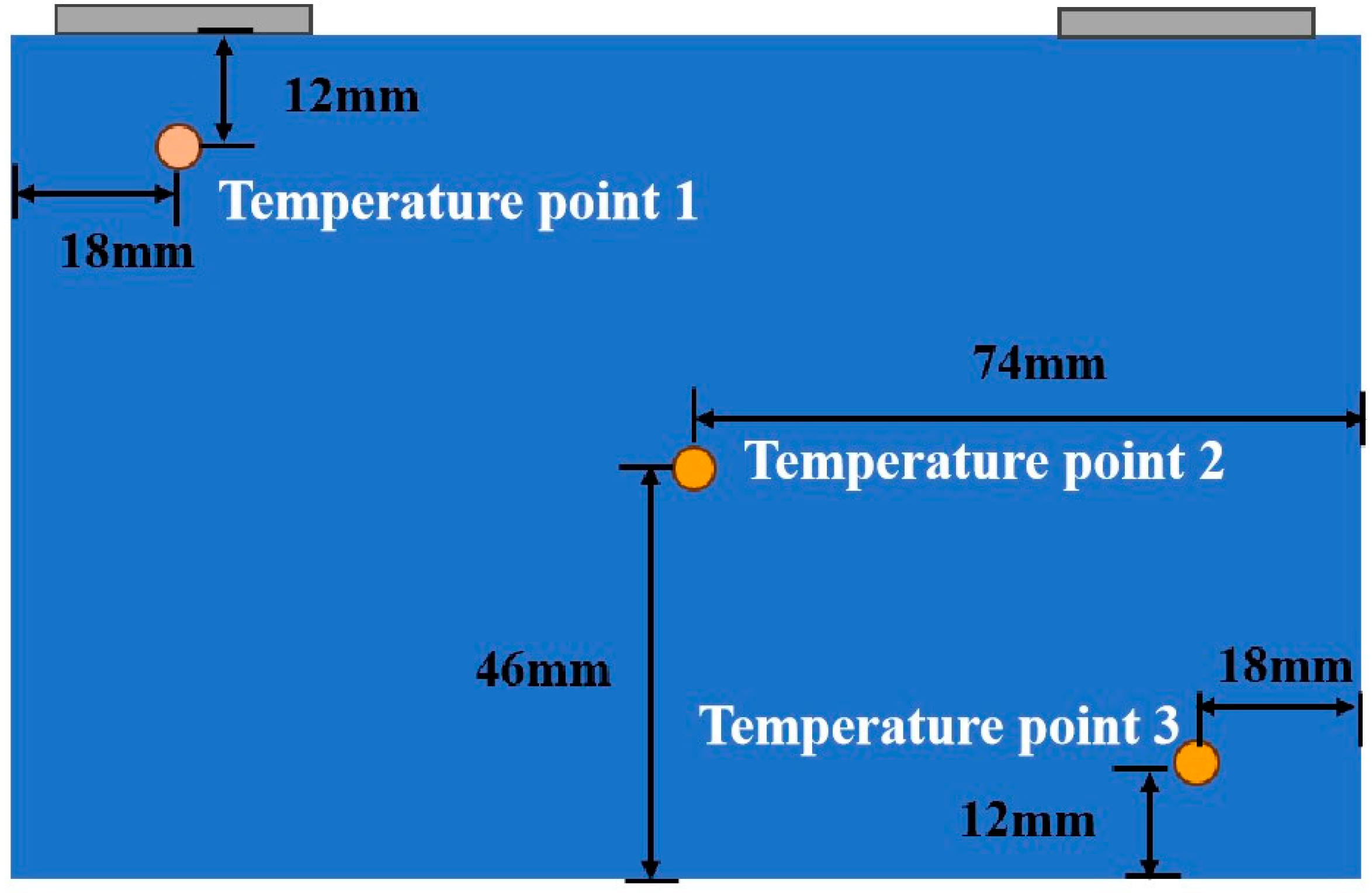
The experimental setup comprises a battery module, environmental chamber, battery testing system, data acquisition instruments, a water pump, and a numerical control temperature bath. A schematic diagram of the experimental equipment is shown in Figure 2. To provide a constant ambient temperature, the battery module is housed within the environmental chamber. The battery testing system is utilized for charging and discharging the battery, and for transmitting charge and discharge information to a computer terminal. The numerical control temperature bath is employed to heat the cooling medium, thereby providing the required liquid inlet temperature with a temperature regulation fluctuation of ±0.1 °C. A water pump is used to circulate the cooling medium, allowing for real-time adjustment of the flow rate, which is adjustable from 50 to 100 mL/min in this experiment. The appropriate pump head parameters are selected for transport based on different hose sizes. A K-type thermocouple and data collection device form the data acquisition system, which is used to measure temperatures at various points on the battery module. As depicted in Figure 3, nine K-type thermocouples are arranged on the inner sides of two batteries and the outer surface of one battery to record temperature data from different measurement points, thereby obtaining the Tmax of the battery pack and the ΔT within the battery pack. Table 2 contains information regarding the experimental setup.

2.3. Description of the Test Setup

To investigate the effectiveness of the constructed lithium-ion battery liquid cooling thermal management system, this study employed an NPCME with varying phase change temperatures as the cooling medium. The aim was to examine how discharge rates, flow rates, and the inlet temperature of the nano emulsion affect the system’s temperature control performance and the utilization efficiency of the nano emulsion’s phase change latent heat. The experiment was primarily divided into three parts, with each set of experimental conditions applied to conduct the experiment three times. The final data were obtained by calculating the average values to eliminate the influence of uncertain factors. The specific testing plan is described as follows.
To explore the temperature control performance of the nano emulsion under different discharge rates, deionized water and octadecane nano phase change emulsion were used as cooling media for comparison. The experiments were conducted at discharge rates of 1.5 C, 1.75 C, and 2 C. A control group was also set up to assess the cooling effect. The ambient temperature of the battery pack during the experiment was 25 °C, with a cooling liquid inlet temperature of 22.5 °C ± 0.3 °C and a constant liquid flow rate of 100 mL/min.
To investigate the temperature control performance of the nano emulsion under different liquid flow rates, the battery pack was discharged at a constant rate of 2 C, using NPCME-n-OD and NPCME-n-E as the cooling media. The inlet flow rate of the cooling liquid was varied to 50 mL/min, 75 mL/min, and 100 mL/min, with the outlet temperature of the cooling liquid being recorded as well. The ambient temperature and the cooling liquid inlet temperature remained unchanged.
To explore the temperature control performance of the nano emulsion under different cooling liquid inlet temperatures, the battery pack was discharged at a constant rate of 2 C, using NPCME-n-E as the cooling medium. The inlet temperatures were set to 22.5 °C and 30 °C, with flow rates of 50 mL/min, 75 mL/min, and 100 mL/min, while other conditions remained constant. A summary of all the experimental conditions is presented in Table 3.

3. Results and Discussion

3.1. Thermo-Physical Properties of the NPCMEs

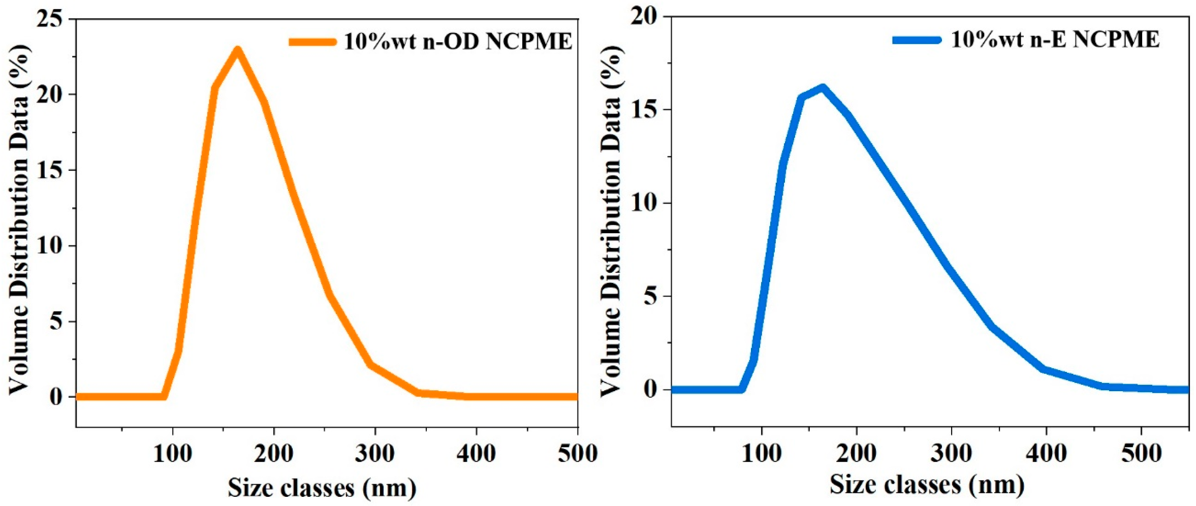
Figure 4 illustrates the particle size distribution of the two nano emulsions. As shown, the particle size of the NPCME-n-OD is primarily distributed between 100 nm and 350 nm, with an average Z-ave particle size of 208.4 nm and a PDI (Polydispersity Index) value of 0.272. The 10 wt% eicosane nano emulsion exhibits a particle size distribution ranging from 100 to 400 nm, with an average Z-ave particle size of 187.6 nm and a PDI value of 0.060.
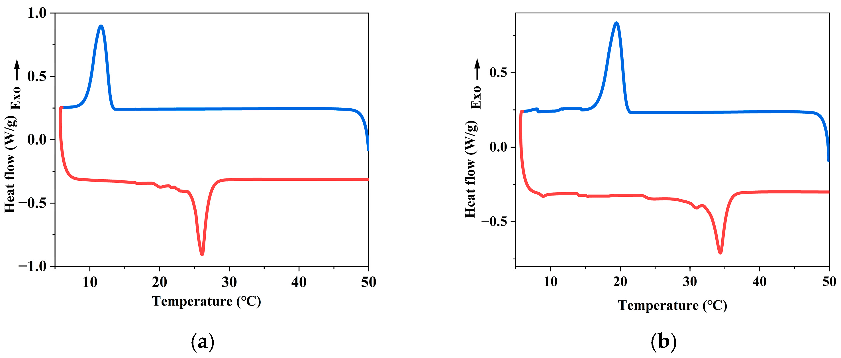
Figure 5 displays the DSC test curves for the two nanophase change emulsions. The test results indicate that the phase change interval for the NPCM-n-OD during endothermic absorption is approximately 25–28 °C, with the exothermic phase change interval ranging from 8 °C to 13 °C. For the NPCME-n-E, the endothermic phase change interval is about 32 °C to 36 °C, and the exothermic phase change temperature is around 15 °C to 20 °C. It can be observed that after the phase change material is formulated into a nano emulsion, there is a significant degree of supercooling present, meaning that its solidification temperature is noticeably lower than its melting temperature. Compared to solid phase change materials, the nano emulsion has smaller particle sizes, making nucleation more difficult, thus resulting in supercooling phenomena. Additionally, the melting enthalpies of the octadecane and eicosane nano emulsions are similar.
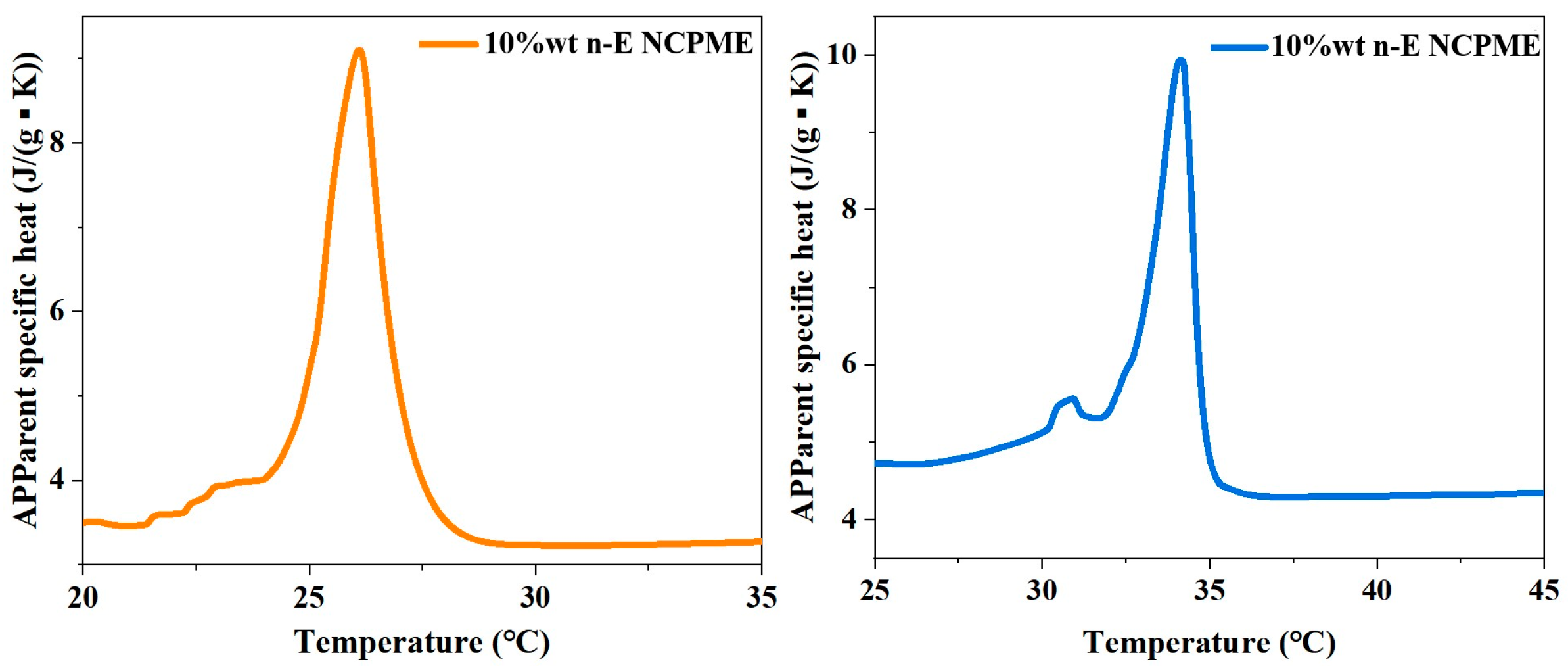
Figure 6 illustrates the variation of apparent specific heat capacity with temperature for two types of nano emulsions. As depicted, the apparent specific heat capacity of the NPCME-n-OD significantly increases as the temperature approaches its phase change temperature, notably higher than that of water, which is 4.2 J g−1·K−1. Specifically, the maximum apparent specific heat capacity of the NPCME-n-OD reaches 9.1 J·g−1·K−1, while that of the NPCME-n-E reaches up to 9.9 J·g−1·K−1, representing 2.1 and 2.4 times that of water, respectively. With rising temperatures, the encapsulated phase change materials within the nano emulsions reach their phase transition temperatures, gradually melting from solid to liquid and absorbing considerable heat, leading to a pronounced enhancement in apparent specific heat capacity. Once the phase change is complete and the temperature continues to rise, the absence of latent heat for phase change results in a gradual decrease in apparent specific heat capacity. It is evident that selecting appropriate operating temperatures in practical applications will better harness the emulsion’s latent heat, enhancing its thermophysical properties. Comparing the octadecane and eicosane nano emulsions reveals that as the inherent phase change temperatures of the emulsions increase, their maximum apparent specific heat capacities are slightly elevated as well. Table 4 summarizes the thermophysical properties of octadecane, eicosane, and their respective nano emulsions.

3.2. Cooling Performance of NPCMEs

3.2.1. Thermal Management Performance at Various Discharge Rates

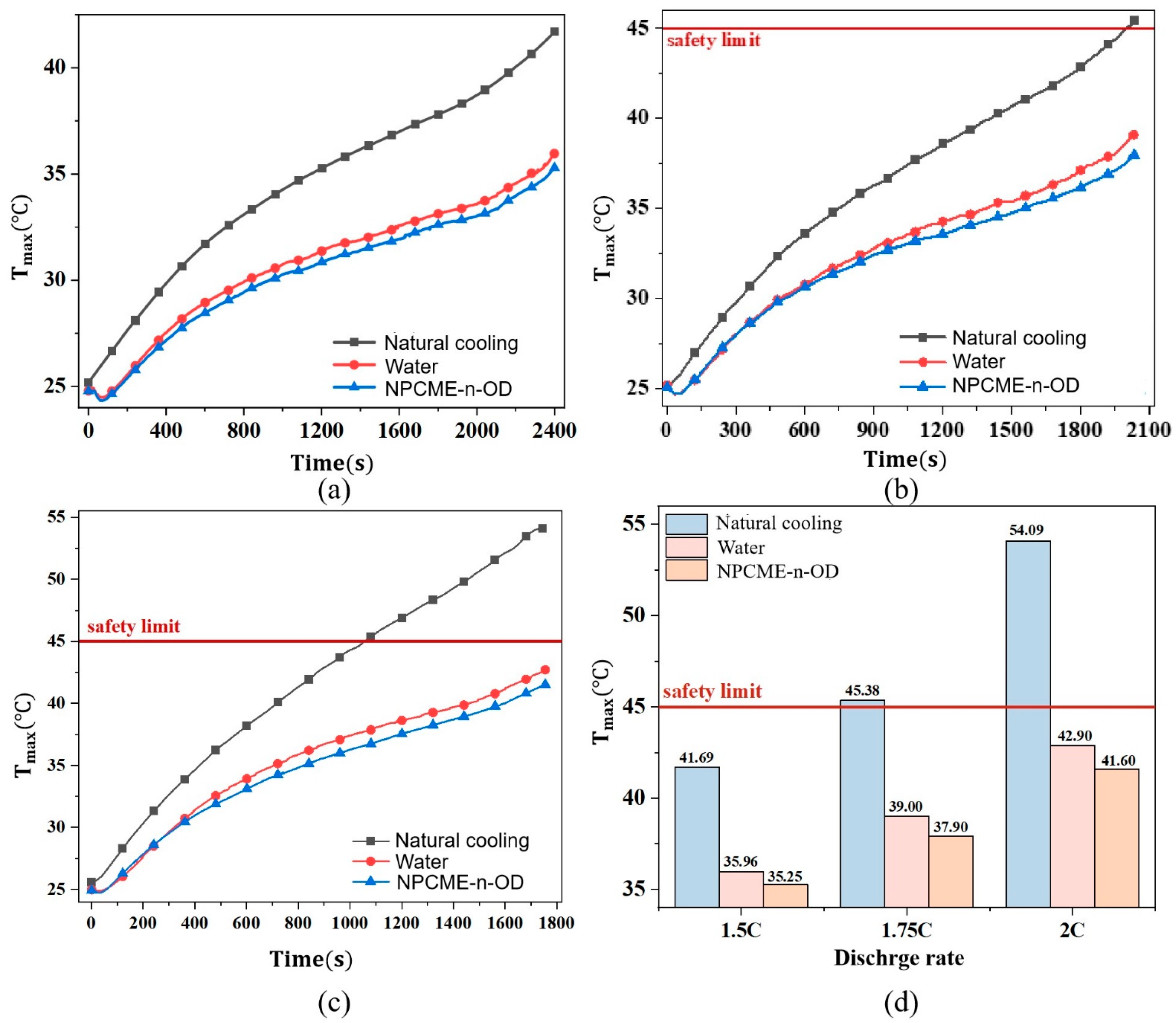
To investigate the thermal management performance of nano emulsions, liquid cooling experiments were conducted on the battery packs at various discharge rates (1.5 C, 1.75 C, and 2 C) for the control group, water cooling group, and nano emulsion cooling group. Figure 7 illustrates the Tmax of the battery packs under different discharge rates using the three thermal management methods.
Figure 7a,b depict the temperature variations of the battery pack under different cooling conditions at 1.5 C and 1.75 C discharge rates, respectively. Regardless of the discharge rate, both the control group and the liquid-cooled groups using various coolants exhibit a similar temperature change pattern: an initial rapid temperature increase, followed by a deceleration, and a subsequent acceleration towards the end of discharge. This pattern is attributed to the heat generation primarily caused by joule heating due to internal resistance, leading to a sharp rise in battery temperature during the early discharge phase when the State of Charge (SOC) is above 0.7. As discharge progresses, the internal resistance decreases and stabilizes, resulting in a more constant heat generation rate, which explains the moderate temperature change when 0.3 < SOC < 0.7. In the later discharge phase, when SOC is below 0.3, the internal resistance increases again, causing the heat generation rate to rise and the battery temperature to climb significantly. Comparing the two discharge rates, the 1.75 C rate, with its higher current, results in more heat generation. Consequently, the temperature of the naturally cooled group reaches 45.38 °C by the end of discharge, exceeding the safe operating range, and all liquid-cooled groups exhibit higher temperatures compared to the 1.5 C rate. The temperature difference between the control group and the liquid-cooled modules widens as heat accumulates, highlighting the increasingly pronounced cooling effect of the liquid cooling. For instance, at 1.75 C, the Tmax of the water-cooled and NPCME-n-OD groups is 6.4 °C and 7.5 °C lower, respectively, than that of the naturally cooled group, demonstrating the significant cooling effect of liquid cooling.
Figure 7c illustrates the temperature changes of the battery pack during a 2 C discharge under three cooling methods. At this higher discharge rate, heat generation is more intense. The temperature of the control group reached 45 °C by 1060 s and approached 55 °C at the end of discharge. The liquid-cooled groups maintained effective temperature control, with both the water-cooled and the NPCME-n-OD groups keeping the battery temperature within a safe range, reducing the Tmax by 10.7 °C and 12.2 °C, respectively, compared to the control group. This highlights the significant advantage of liquid cooling in enhancing heat dissipation.
Figure 7d presents the Tmax of the battery pack under different discharge rates and cooling methods. Overall, the adoption of liquid cooling significantly reduced the highest battery temperatures. The Tmax of the battery pack in the nano emulsion group was consistently lower than that in the water-cooled group, with this difference becoming more pronounced as the discharge rate increased, indicating a more significant temperature control effect of the nano emulsion. At the three discharge rates, the Tmax in the nano emulsion group was 0.7 °C, 1.1 °C, and 1.3 °C lower than that in the water-cooled group, respectively. This is because, at these rates, the outlet temperature of the NPCME-n-OD reached the phase change temperature by the end of discharge. As the discharge rate increased, the heat generation in the battery also increased. Therefore, when cooling batteries at high discharge rates, the nano emulsion absorbs more heat and reaches the phase change temperature earlier, better utilizing its latent heat of fusion. Consequently, the cooling effect of the nano emulsion is enhanced more at higher discharge rates compared to water.
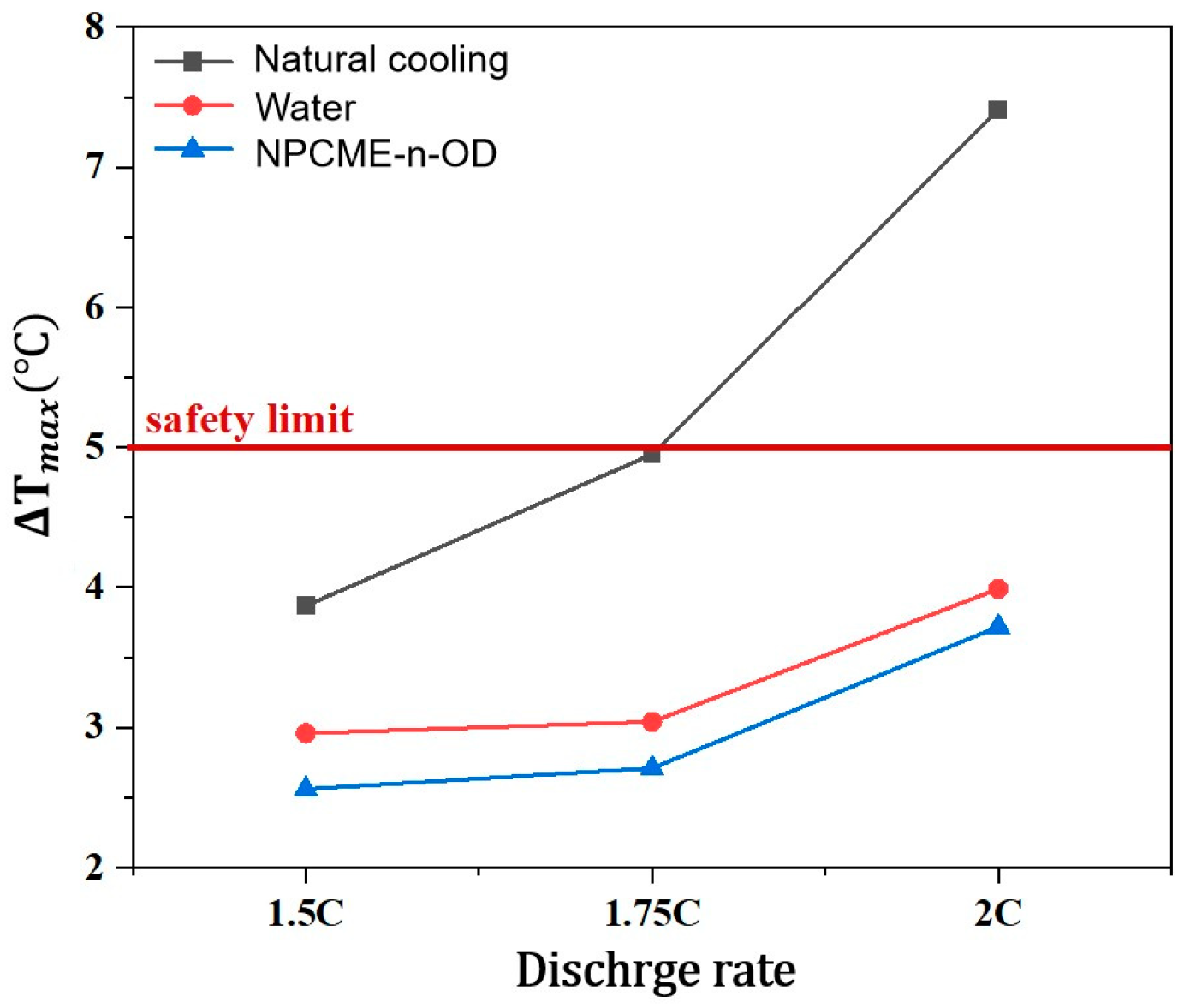
Figure 8 displays the ΔTmax within the battery pack under various cooling methods and discharge rates. It is observable that the ΔTmax across the battery pack increases with higher discharge rates. Under natural cooling conditions, the ΔTmax at 2 C exceeds 5 °C. This is attributed to the poor heat dissipation on the inner sides of the battery pack under natural cooling, where the outer sides have better heat dissipation conditions, leading to heat accumulation in the center and a significant temperature gradient within the battery pack. Incorporating a cold plate between the batteries effectively enhances heat dissipation on the inner sides, reducing the disparity with external cooling conditions. A further comparison of two cooling media reveals that the nano emulsion group exhibits better temperature uniformity than the water-cooled group. This may be due to the high apparent specific heat capacity of the nano emulsion near its phase change temperature, which endows it with superior heat storage and temperature control capabilities. Therefore, employing octadecane nano emulsion as a cooling medium, which undergoes phase change at 25–28 °C, can improve the temperature uniformity of the battery pack.
Figure 9a presents the outlet temperatures of NPCME-n-OD at various discharge rates. The outlet temperature increases with higher discharge rates. At a 1.5 C discharge rate, the outlet temperature only reaches 25.5 °C by the end of discharge, just touching the phase change initiation temperature of 25 °C, without fully utilizing its heat storage capacity. At discharge rates of 1.75 C and 2 C, the outlet temperature exceeds the phase change initiation temperature by 1 °C, reaching 26 °C, indicating the beginning of heat absorption through the latent heat of the nano emulsion. Due to certain errors in the measurement of the emulsion’s outlet temperature, to ensure that the nano emulsion has indeed undergone phase change, this study set the phase change determination temperature for NPCME-n-OD at 26 °C and for NPCME-n-E at 33 °C, ensuring complete phase change upon reaching these temperatures. Figure 9b illustrates the variation in the outlet temperature of NPCME-n-OD over time at different discharge rates. At a 1.75 C discharge rate, the outlet temperature reaches 26.00 °C by the 1800 s. For the 2 C discharge rate, the outlet temperature is 26.59 °C at the end of discharge, and it reaches 26.00 °C by the 1413 s. It can be observed that as the discharge rate increases, the heat generation from the battery also increases, and the time for the nano emulsion to undergo phase change is advancing. At higher discharge rates, the latent heat of the nano emulsion can be more fully utilized.

3.2.2. Thermal Management Performance of NPCMEs at Various Liquid Flow Rates

Nano emulsions, with their dual attributes of fluidity and the heat storage capacity of phase change materials, offer a promising avenue for thermal management. However, the convective heat transfer in liquid cooling must be considered alongside the availability of sufficient time for the flowing phase change material to exchange heat with the battery and to warm up to the phase change temperature. Therefore, further investigation into the impact of the flow rate of the nano emulsion on its thermal control effectiveness is warranted.
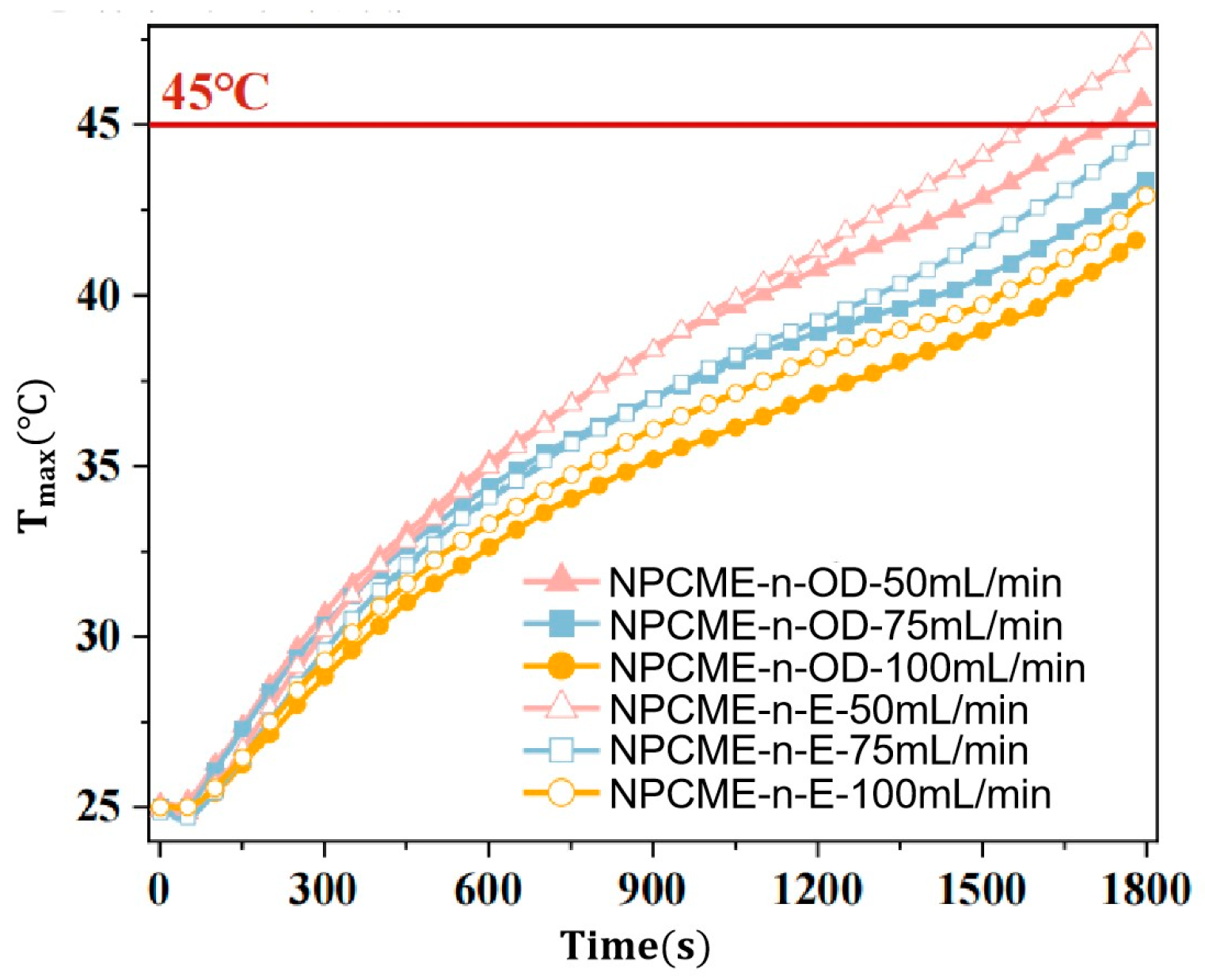
Figure 10 illustrates the temperature changes of the battery pack at a 2 C discharge rate under different nano emulsion phase change temperatures and flow rates. It is evident that when using nano emulsions with varying phase change temperatures as coolants, the Tmax of the battery pack decreases with an increase in flow rate, indicating that an enhanced convective heat transfer between the coolant and the battery is achieved, thereby improving the liquid cooling effect. Additionally, the Tmax for the NPCME-n-E is consistently higher than that for the NPCME-n-OD. This may be attributed to the fact that at an inlet temperature of 22.5 °C, the NPCME-n-OD is more prone to phase change compared to the NPCME-n-E, leading to a significant increase in the apparent specific heat capacity of the NPCME-n-OD near its phase change temperature, which can absorb more heat from the battery. Therefore, employing NPCME-n-OD with a phase change occurring at 25–28 °C as a cooling medium can enhance the temperature uniformity of the battery pack.
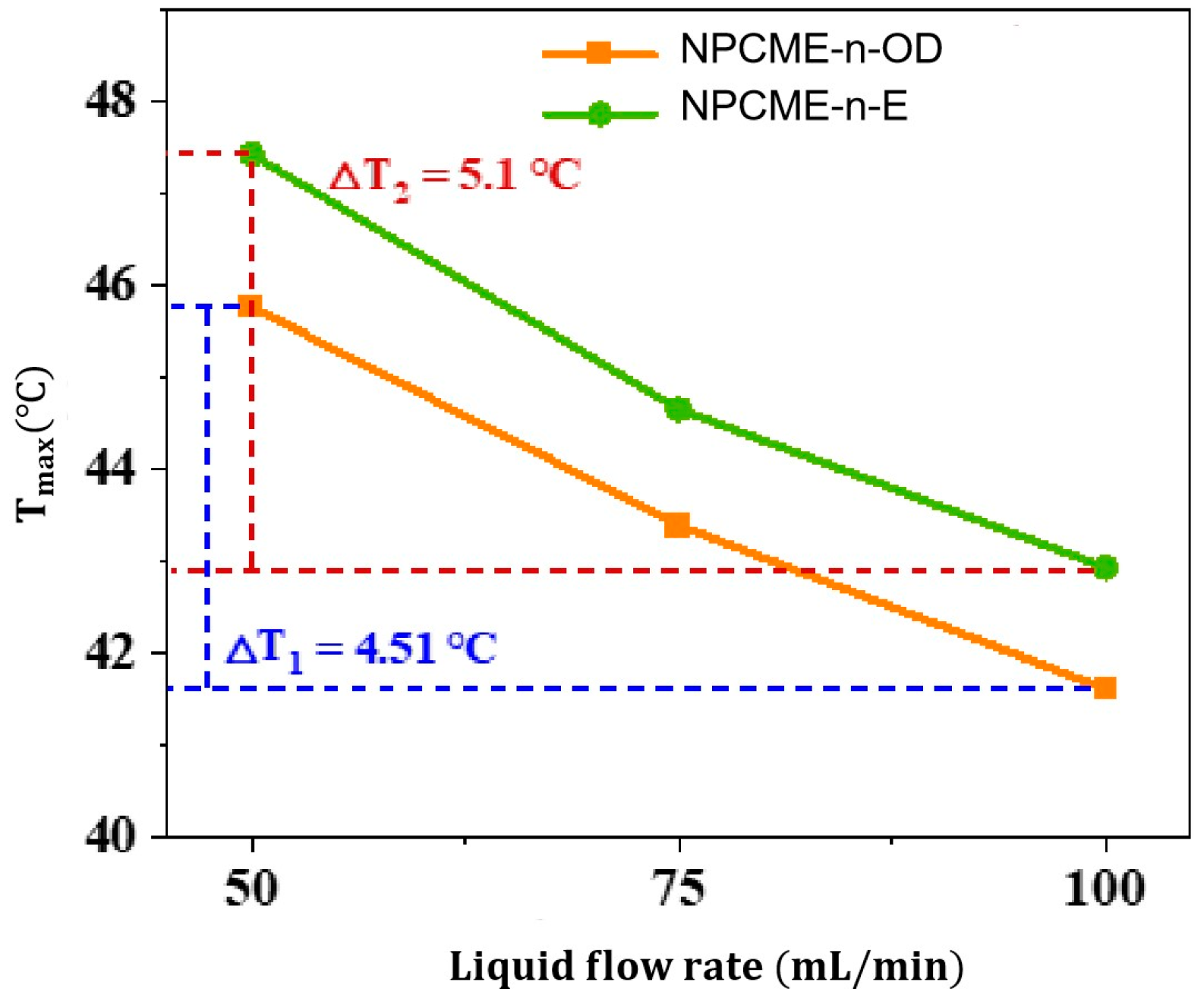
Figure 11 presents the Tmax of the battery pack under various flow rates and cooling media. It is observed that as the flow rate increases, the impact of liquid cooling on the Tmax decreases. When the flow rate increases from 50 mL/min to 75 mL/min, the temperature change is most pronounced, with the NPCME-n-OD group and the NPCME-n-E group experiencing decreases of 2.73 °C and 3.37 °C, respectively. When the flow rate further increases from 75 mL/min to 100 mL/min, the Tmax of both groups decrease by 1.78 °C and 1.73 °C, respectively. This indicates that the effect of increasing flow rate on battery temperature is limited. Overall, when the flow rate is increased from 50 mL/min to 100 mL/min, the temperature reduction is significant in both scenarios. Specifically, enhancing the flow rate has a better optimization effect on the thermal control performance of the NPCME-n-E. In comparison, the impact on the NPCME-n-OD is less pronounced. The reason may be that at these three flow rates, the NPCME-n-OD undergoes phase change, and with the increase in flow rate and velocity, the degree of phase change in the nano emulsion decreases. Consequently, although the overall cooling effect of NPCME-n-OD improves with increased flow velocity, the enhancement in its liquid cooling effect is less significant than that of the NPCME-n-E due to the reduced extent of phase change utilization.
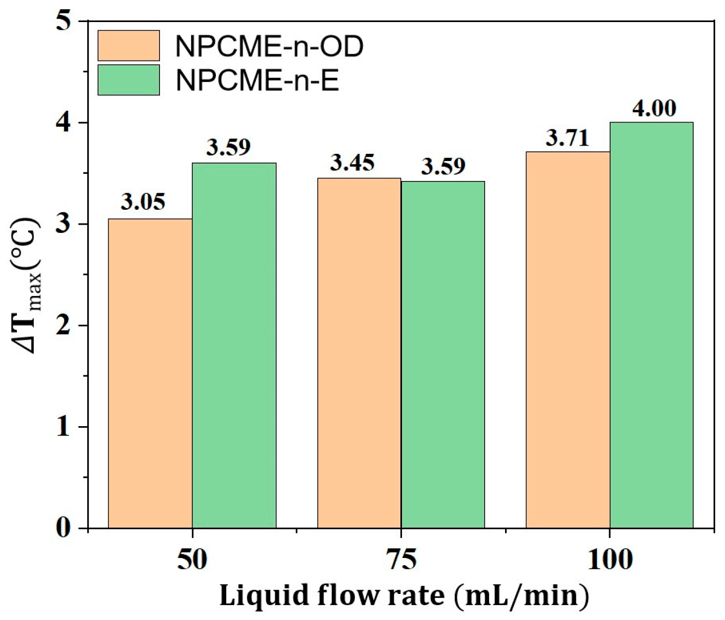
Figure 12 illustrates the ΔTmax within the battery pack during 2 C discharge under different cooling media and flow rates. Contrary to the pattern observed for the Tmax of the battery pack, the ΔTmax increases with the enhancement of flow rate. This phenomenon can be attributed to the single-channel cold plate used in the experiment, with inlets and outlets positioned diagonally opposite on the sides, resulting in a long channel. As the cooling medium flows through the liquid cooling channel, its temperature rises due to heat absorption from the battery, leading to lower heat dissipation efficiency at the outlet compared to the inlet. Although the heat dissipation condition at the outlet is improved with increased flow velocity, the improvement in heat dissipation effect is not as significant as at the inlet. Consequently, while the overall heat dissipation efficiency of the battery pack improves, the ΔTmax within the battery pack actually increases. The data presented in the figure indicate that both nano emulsions can control the ΔTmax within the battery pack to below 5 °C, with the ΔTmax in the NPCME-n-OD group consistently lower than that in the NPCME-n-E group. The likely reason is that the NPCME-n-E did not reach the phase change temperature, whereas the NPCME-n-OD underwent phase change, exhibiting a higher apparent specific heat capacity and stronger heat storage capability, thus better maintaining the temperature uniformity within the battery pack.
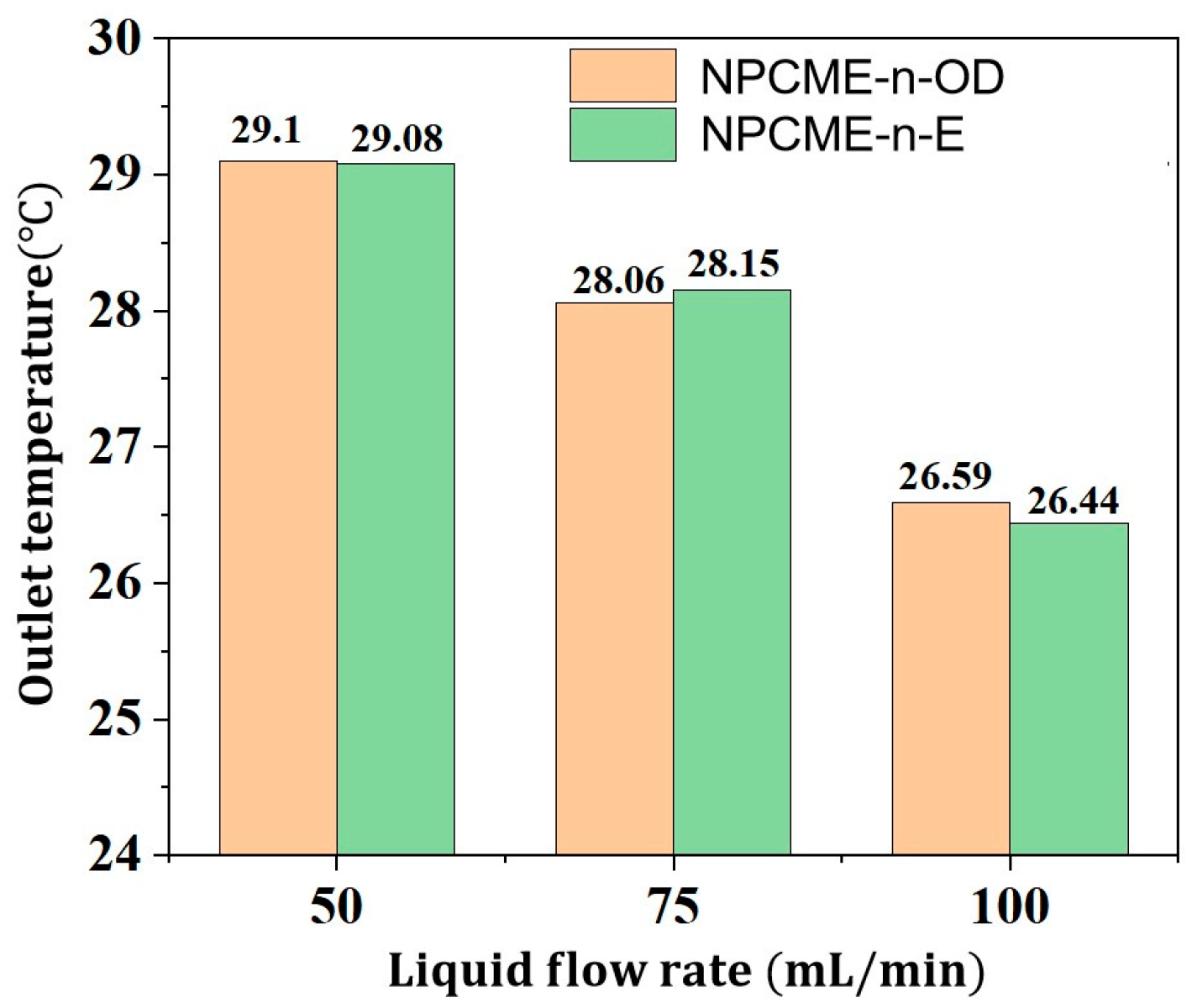
Figure 13 presents the highest outlet temperatures of two nano emulsions with different phase change temperatures at the end of discharge. The figure indicates that the outlet temperature of the nano emulsion decreases with increasing flow rate, and the outlet temperatures of the two different nano emulsions are essentially similar at the same flow rate. Specifically, the highest outlet temperatures at the end of discharge for the NPCME-n-OD are 29.1 °C (50 mL/min), 28.06 °C (75 mL/min), and 26.59 °C (100 mL/min), all of which exceed the phase change temperature, demonstrating that the NPCME-n-OD has undergone phase change and utilized its latent heat to absorb more heat generated by the battery. The highest outlet temperatures at the end of discharge for the NPCME-n-E are 29.08 °C (50 mL/min), 28.15 °C (75 mL/min), and 26.44 °C (100 mL/min), none of which reach the phase change temperature of the NPCME-n-E, thus not fully utilizing its latent heat and offering limited enhancement to the cooling effect of the battery pack. Although the temperature increases of the two emulsions are similar, within this temperature range, the apparent specific heat capacity of the NPCME-n-OD is greater than that of the NPCME-n-E, meaning it absorbs more heat for the same temperature rise, resulting in lower battery temperatures for the NPCME-n-OD group. In summary, increasing the flow rate can enhance the convective heat transfer effect of the liquid. Although this implies a reduced degree of phase change for the nano emulsion, the overall thermal management performance of the system based on the nano phase change emulsion also improves with the increased flow rate. This suggests that the enhanced convective heat transfer effect from increasing the flow rate outweighs the loss of latent heat from phase change. Additionally, it should be considered that increasing the flow rate leads to higher energy consumption; therefore, it is necessary to balance the liquid cooling effect and phase change heat absorption to ensure optimal thermal control performance while minimizing energy usage.

3.2.3. Thermal Management Performance of NPCMEs at Different Inlet Temperatures and Flow Rates

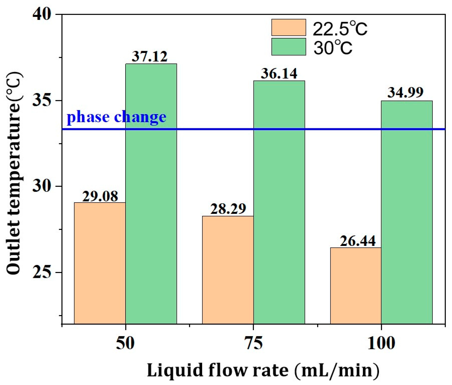
As indicated in Section 3.2.1 and Section 3.2.2, for the NPCME-n-E, at an inlet temperature of 22.5 °C, its own phase change temperature is too high. Even at a 2 C discharge rate and a low flow rate of 50 mL/min, its maximum outlet temperature does not reach the phase change temperature. In this section, we discuss whether increasing the inlet temperature of the NPCME-n-E, which has a higher phase change temperature, can enable it to utilize its phase change latent heat and enhance the cooling effect. The battery pack discharge rate is maintained at 2 C, and the NPCME-n-E is used for battery thermal management experiments at different inlet temperatures (22.5 °C and 30 °C) and various flow rates (50 mL/min, 75 mL/min, and 100 mL/min).
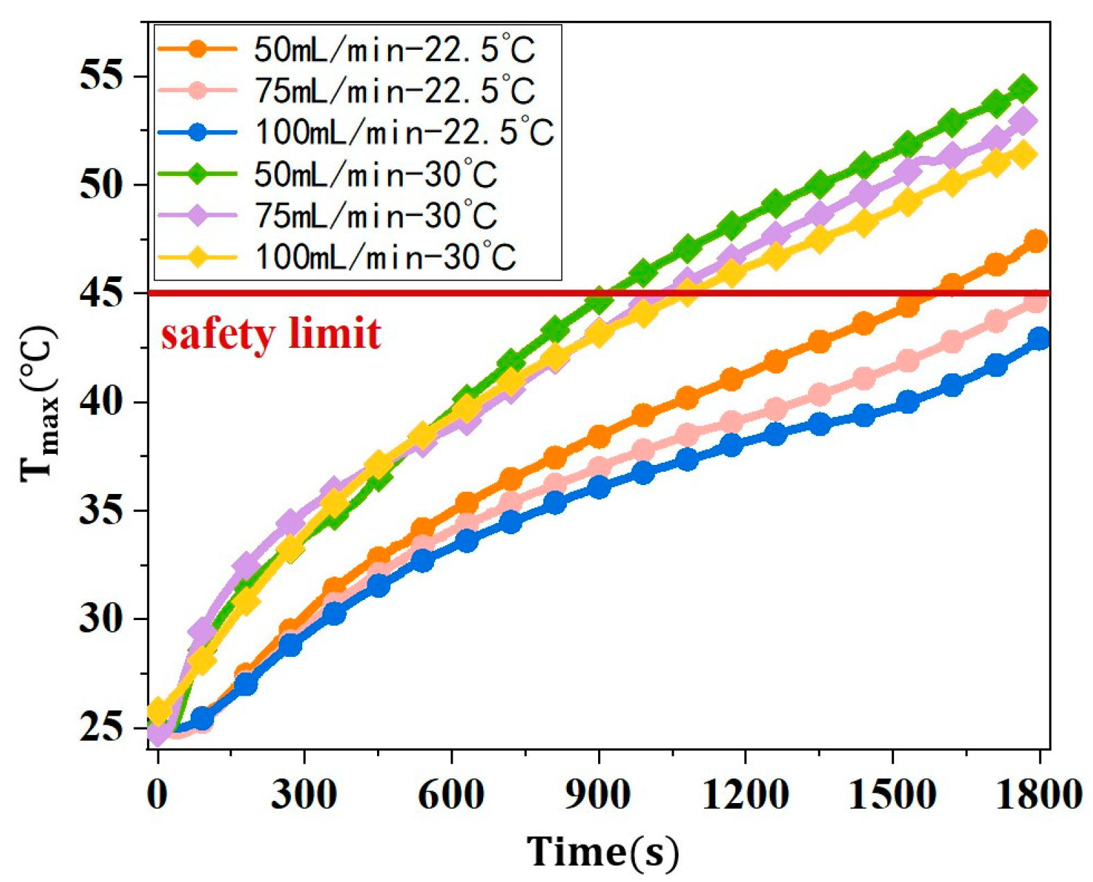
Figure 14 illustrates the Tmax of the battery pack when using NPCME-n-OD as the coolant, under various inlet temperatures and flow rates. It can be observed that for different inlet temperatures, the Tmax of the battery pack decreases with increasing flow rate. Among battery packs with the same coolant flow rate, the inlet temperature of 22.5 °C is significantly lower than that at 30 °C. This may be attributed to the fact that with an ambient temperature of 25 °C for the battery pack, when the inlet temperature is 30 °C, the coolant is initially warmer than the battery pack, failing to dissipate heat and instead causing the temperature of the battery pack to rise. In contrast, at an inlet temperature of 22.5 °C, the coolant’s initial temperature is lower than that of the battery pack, enabling effective heat exchange. Therefore, at flow rates of 75 mL/min and 100 mL/min, the maximum temperature of the battery pack can be controlled below 45 °C.
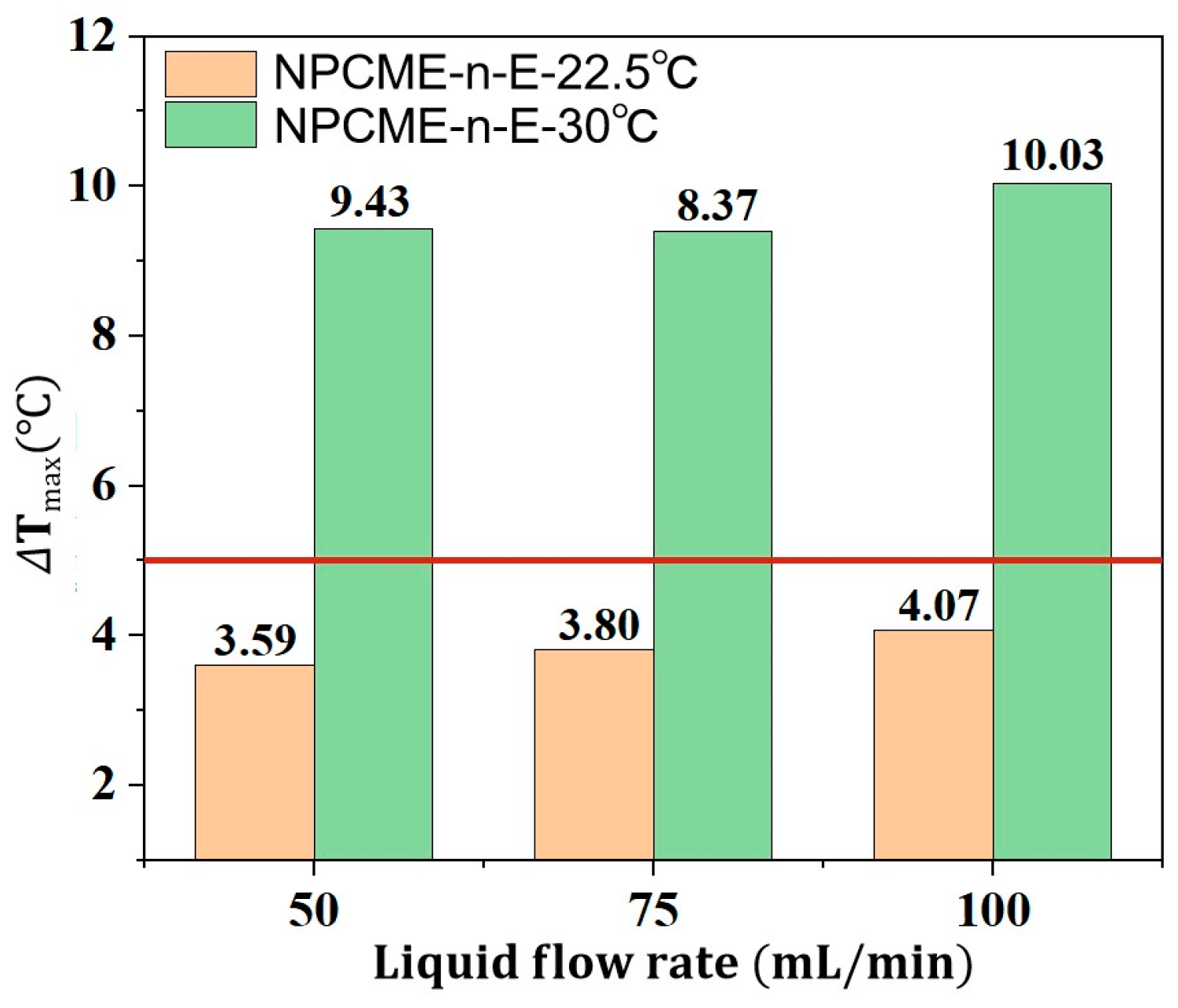
Figure 15 displays the ΔTmax within the battery pack at various inlet temperatures and flow rates. It is evident that at the inlet temperature of 22.5 °C and across the three different flow rates, the battery pack exhibits a favorable temperature distribution. However, as the inlet temperature increases, the degree of temperature non-uniformity within the battery pack gradually intensifies.
Figure 16 presents the maximum outlet temperatures of NPCME-n-E at different inlet temperatures. As depicted, when the inlet temperature is increased from 22.5 °C to 30 °C, the outlet temperature of the coolant also rises but decreases with the increase in flow rate. At the condition of 30 °C, the outlet temperatures under various flow rates all exceed the phase change temperature. Therefore, increasing the inlet temperature is an effective method to enhance the utilization of latent heat. Overall, raising the inlet temperature to 30 °C can induce phase change in the phase change emulsion, leveraging the effect of latent heat. However, the Tmax of the battery pack under the condition of a 30 °C inlet temperature is significantly higher than that with an inlet temperature of 22.5 °C. After increasing the inlet temperature, the utilization rate of the phase change material’s latent heat is improved, but an excessively high inlet temperature leads to reduced liquid cooling efficiency, resulting in the decreased thermal control performance of the nano emulsion. This indicates that the increased utilization rate of latent heat cannot compensate for the convective heat transfer effect sacrificed by raising the coolant temperature. Therefore, for the battery thermal management system proposed in this paper, increasing the inlet temperature of NPCME-n-E, even exceeding the initial temperature of the battery, does not take into account both the thermal management performance and the utilization of latent heat of the nano emulsion. It is possible to try to increase the heat absorbed by the emulsion by adjusting the contact time between the nano emulsion and the battery under the condition of a lower inlet temperature.

4. Conclusions

In this study, we prepared two types of nano phase change material emulsions (NPCMEs) with different phase change temperatures as cooling media for a battery thermal management system and investigated their performance. Experiments were conducted to compare the thermal management capabilities of the NPCMEs with natural convection and water cooling, and the effects of different flow rates and coolant inlet temperatures on cooling performance were studied. The specific conclusions are as follows:
  • The prepared NPCME-n-OD and NPCME-n-E have phase change onset temperatures of approximately 25.5 °C and 32.5 °C, respectively, with particle sizes mainly distributed between 100 and 400 nm and melting enthalpies of 16.9 J/g and 18.4 J/g, respectively. Test results show that the apparent specific heat capacities of the NPCME-n-OD and the NPCME-n-E are significantly higher than that of water, being 2.1 and 2.4 times that of water, respectively.
  • The phase change temperature significantly affects the temperature control performance of NPCMEs, especially when it is close to the ambient temperature, where their performance is superior to water. For example, the NPCME-n-OD with a phase change temperature of 25–28 °C, at an inlet temperature of 22.5 °C, achieves a maximum temperature (Tmax) of 37.9 °C during a 1.75 C discharge rate, which is significantly lower than that of natural convection and water cooling. As the discharge rate increases, the cooling effect of NPCMEs becomes more pronounced due to the increased utilization rate of latent heat.
  • With the increase in the NPCME’s flow rate, although the temperature of the battery pack is reduced, the utilization efficiency of the latent heat of the nano emulsion decreases, and the system energy consumption increases. Increasing the flow rate can enhance the convective heat transfer effect, which, to some extent, compensates for the loss of thermal management performance due to the reduction of phase change heat absorption. However, rapid flow also means higher energy consumption. Therefore, when using nano emulsions for thermal management, it is necessary to balance the dual impact of flow rate on thermal performance and energy consumption.
  • For nano emulsions with higher phase change temperatures, such as the NPCME-n-E, increasing the inlet temperature can induce phase change and utilize latent heat, but the overall thermal control performance remains suboptimal. While an inlet temperature below the ambient temperature does not readily cause phase change, effective liquid cooling can still maintain battery temperatures within the desired range. Conversely, raising the inlet temperature to near the phase change point can result in a poor cooling efficiency due to the higher initial battery temperature, potentially compromising battery safety. Therefore, when the phase change temperature significantly exceeds the initial battery temperature, it is not advisable to rely on increased inlet temperatures to enhance latent heat utilization. Instead, consider adjusting the contact time between the nano emulsion and the battery at lower inlet temperatures to increase heat absorption.
Overall, this research represents a preliminary exploration into the application of NPCMEs for high-capacity ternary lithium-ion batteries. Nonetheless, the present study’s scope was confined by technical limitations, precluding a thorough examination of supercooling effects, which are pivotal for the transition to engineering applications. Addressing this gap is a priority for our future investigations, with the aim of advancing the practical utilization of NPCMEs in thermal management systems.

Author Contributions

Conceptualization, G.Z. and T.L.; methodology, Z.X.; software, Y.L.; validation, T.L. and Z.X.; formal analysis, G.Z.; investigation, G.Z.; resources, P.L.; data curation, T.L.; writing—original draft preparation, Z.X.; writing—review and editing, Z.X. and T.L.; visualization, G.Z. and Z.X.; supervision, Y.L.; project administration, G.C.; funding acquisition, G.C. and P.L. All authors have read and agreed to the published version of the manuscript.

Funding

This research was supported by the Key R&D Program of Hubei Province, grant number 2023BEB021); the National innovation and entrepreneurship training program for college students, grant number 202310497002.

Institutional Review Board Statement

Not applicable.

Informed Consent Statement

Not applicable.

Data Availability Statement

Dataset available on request from the authors.

Conflicts of Interest

Authors Guofeng Chen and Pan Li were employed by the company Wuhan Second Institute of Ship Design and Research. The remaining authors declare that the research was conducted in the absence of any commercial or financial relationships that could be construed as a potential conflict of interest.

References

  1. Xie, N.; Zhang, Y.; Liu, X.; Luo, R.; Liu, Y.; Ma, C. Thermal performance and structural optimization of a hybrid thermal management system based on MHPA/PCM/liquid cooling for lithium-ion battery. Appl. Therm. Eng. 2023, 235, 121341. [Google Scholar] [CrossRef]
  2. Xu, B.; Lee, J.; Kwon, D.; Kong, L.; Pecht, M. Mitigation strategies for Li-ion battery thermal runaway: A review. Renew. Sustain. Energy Rev. 2021, 150, 111437. [Google Scholar] [CrossRef]
  3. Ramadass, P.H.B.W.R.P.B.; Haran, B.; White, R.; Popov, B.N. Capacity fade of Sony 18650 cells cycled at elevated temperatures Part I. Cycling performance. J. Power Sources 2002, 112, 602–613. [Google Scholar] [CrossRef]
  4. Ramadass, P.H.B.W.R.P.B.; Haran, B.; White, R.; Popov, B.N. Capacity fade of Sony 18650 cells cycled at elevated temperatures Part II. Capacity fade analysis. J. Power Sources 2002, 112, 614–620. [Google Scholar] [CrossRef]
  5. Akbarzadeh, M.; Jaguemont, J.; Kalogiannis, T.; Karimi, D.; He, J.; Jin, L.; Berecibar, M. A novel liquid cooling plate concept for thermal management of lithium-ion batteries in electric vehicles. Energy Convers. Manag. 2021, 231, 113862. [Google Scholar] [CrossRef]
  6. Yue, Q.L.; He, C.X.; Wu, M.C.; Zhao, T.S. Advances in thermal management systems for next-generation power batteries. Int. J. Heat Mass Transf. 2021, 181, 121853. [Google Scholar] [CrossRef]
  7. Hasan, H.A.; Togun, H.; Abed, A.M.; I Mohammed, H.; Biswas, N. A novel air-cooled Li-ion battery (LIB) array thermal management system–a numerical analysis. Int. J. Therm. Sci. 2023, 190, 108327. [Google Scholar] [CrossRef]
  8. Ye, J.; Aldaher, A.Y.M.; Tan, G. Thermal performance analysis of 18,650 battery thermal management system integrated with liquid-cooling and air-cooling. J. Energy Storage 2023, 72, 108766. [Google Scholar] [CrossRef]
  9. Sahin, R.C.; Gocmen, S.; Cetkin, E. Thermal management system for air-cooled battery packs with flow-disturbing structures. J. Power Sources 2022, 551, 232214. [Google Scholar] [CrossRef]
  10. Roe, C.; Feng, X.; White, G.; Li, R.; Wang, H.; Rui, X.; Li, C.; Zhang, F.; Null, V.; Parkes, M.; et al. Immersion cooling for lithium-ion batteries–A review. J. Power Sources 2022, 525, 231094. [Google Scholar] [CrossRef]
  11. Wang, H.; Tao, T.; Xu, J.; Shi, H.; Mei, X.; Gou, P. Thermal performance of a liquid-immersed battery thermal management system for lithium-ion pouch batteries. J. Energy Storage 2022, 46, 103835. [Google Scholar] [CrossRef]
  12. Weng, J.; Xiao, C.; Yang, X.; Ouyang, D.; Chen, M.; Zhang, G.; Waiming, E.L.; Yuen, R.K.K.; Wang, J. An energy-saving battery thermal management strategy coupling tubular phase-change-material with dynamic liquid cooling under different ambient temperatures. Renew. Energy 2022, 195, 918–930. [Google Scholar] [CrossRef]
  13. Zhang, J.; Li, X.; Zhang, G.; Wang, Y.; Guo, J.; Wang, Y.; Huang, Q.; Xiao, C.; Zhong, Z. Characterization and experimental investigation of aluminum nitride-based composite phase change materials for battery thermal management. Energy Convers. Manag. 2020, 204, 112319. [Google Scholar] [CrossRef]
  14. Yang, X.; Huang, R.; Yao, Z.; Zhang, G. Modular assembly strategy to construct lightweight thermal management system by developing high-stable phase change material units. Chem. Eng. Sci. 2024, 299, 120529. [Google Scholar] [CrossRef]
  15. Weragoda, D.M.; Tian, G.; Burkitbayev, A.; Lo, K.-H.; Zhang, T. A comprehensive review on heat pipe based battery thermal management systems. Appl. Therm. Eng. 2023, 224, 120070. [Google Scholar] [CrossRef]
  16. Mohammed, A.G.; Elfeky, K.E.; Wang, Q. Recent advancement and enhanced battery performance using phase change materials based hybrid battery thermal management for electric vehicles. Renew. Sustain. Energy Rev. 2022, 154, 111759. [Google Scholar] [CrossRef]
  17. Wu, W.; Ye, G.; Zhang, G.; Yang, X. Composite phase change material with room-temperature-flexibility for battery thermal management. Chem. Eng. J. 2022, 428, 131116. [Google Scholar] [CrossRef]
  18. Yao, Z.; Xie, J.; Fu, T.; Luo, Y.; Yang, X. One-pot preparation of phase change material employing nano-scaled resorcinol-furfural frameworks. Chem. Eng. J. 2024, 484, 149553. [Google Scholar] [CrossRef]
  19. Hu, S.; Wang, S.; Ma, C.; Zhang, Y. Efficient purification of metal-organic framework and its trigger strategy in battery thermal management system. Energy Convers. Manag. 2023, 292, 117416. [Google Scholar] [CrossRef]
  20. Sabbah, R.; Kizilel, R.; Selman, J.R.; Al-Hallaj, S. Active (air-cooled) vs. passive (phase change material) thermal management of high power lithium-ion packs: Limitation of temperature rise and uniformity of temperature distribution. J. Power Sources 2008, 182, 630–638. [Google Scholar] [CrossRef]
  21. Widyantara, R.D.; Naufal, M.A.; Sambegoro, P.L.; Nurprasetio, I.P.; Triawan, F.; Djamari, D.W.; Nandiyanto, A.B.D.; Budiman, B.A.; Aziz, M. Low-Cost Air-Cooling System Optimization on Battery Pack of Electric Vehicle. Energies 2021, 14, 7954. [Google Scholar] [CrossRef]
  22. Zeng, W.; Niu, Y.; Li, S.; Hu, S.; Mao, B.; Zhang, Y. Cooling performance and optimization of a new hybrid thermal management system of cylindrical battery. Appl. Therm. Eng. 2022, 217, 119171. [Google Scholar] [CrossRef]
  23. Xie, J.; Zhang, G.; Yang, X. Thermal performance analysis of battery thermal management system utilizing bionic liquid cooling plates with differentiated velocity distribution strategy. Appl. Therm. Eng. 2024, 249, 123351. [Google Scholar] [CrossRef]
  24. Patil, M.S.; Seo, J.-H.; Panchal, S.; Jee, S.-W.; Lee, M.-Y. Investigation on thermal performance of water-cooled Li-ion pouch cell and pack at high discharge rate with U-turn type microchannel cold plate. Int. J. Heat Mass Transf. 2020, 155, 119728. [Google Scholar] [CrossRef]
  25. Wang, F.; Lin, W.; Ling, Z.; Fang, X. A comprehensive review on phase change material emulsions: Fabrication, characteristics, and heat transfer performance. Sol. Energy Mater. Sol. Cells 2019, 191, 218–234. [Google Scholar] [CrossRef]
  26. Yu, Q.; Tchuenbou-Magaia, F.; Al-Duri, B.; Zhang, Z.; Ding, Y.; Li, Y. Thermo-mechanical analysis of microcapsules containing phase change materials for cold storage. Appl. Energy 2018, 211, 1190–1202. [Google Scholar] [CrossRef]
  27. Mikkola, V.; Puupponen, S.; Saari, K.; Ala-Nissila, T.; Seppälä, A. Thermal properties and convective heat transfer of phase changing paraffin nanofluids. Int. J. Therm. Sci. 2017, 117, 163–171. [Google Scholar] [CrossRef]
  28. Pey, C.M.; Maestro, A.; Solé, I.; González, C.; Solans, C.; Gutiérrez, J.M. Optimization of nano-emulsions prepared by low-energy emulsification methods at constant temperature using a factorial design study. Colloids Surf. A Physicochem. Eng. Asp. 2006, 288, 144–150. [Google Scholar] [CrossRef]
  29. Zhang, X.; Niu, J.; Wu, J.-Y. Development and characterization of novel and stable silicon nanoparticles-embedded PCM-in-water emulsions for thermal energy storage. Appl. Energy 2019, 238, 1407–1416. [Google Scholar] [CrossRef]
  30. Chen, J.; Zhang, P. Preparation and characterization of nano-sized phase change emulsions as thermal energy storage and transport media. Appl. Energy 2017, 190, 868–879. [Google Scholar] [CrossRef]
  31. Xiang, N.; Yuan, Y.; Sun, L.; Cao, X.; Zhao, J. Simultaneous decrease in supercooling and enhancement of thermal conductivity of paraffin emulsion in medium temperature range with graphene as additive. Thermochim. Acta 2018, 664, 16–25. [Google Scholar] [CrossRef]
  32. Zhang, G.; Yu, Z.; Cui, G.; Dou, B.; Lu, W.; Yan, X. Fabrication of a novel nano phase change material emulsion with low supercooling and enhanced thermal conductivity. Renew. Energy 2020, 151, 542–550. [Google Scholar] [CrossRef]
  33. Zhang, C.; Ji, J.; Zhang, X.; Cai, S. Development of highly stable low supercooling paraffin nano phase change emulsions for thermal management systems. J. Mol. Liq. 2024, 413, 125905. [Google Scholar] [CrossRef]
  34. Wang, F.; Cao, J.; Ling, Z.; Zhang, Z.; Fang, X. Experimental and simulative investigations on a phase change material nano-emulsion-based liquid cooling thermal management system for a lithium-ion battery pack. Energy 2020, 207, 118215. [Google Scholar] [CrossRef]
  35. Cao, J.; He, Y.; Feng, J.; Lin, S.; Ling, Z.; Zhang, Z.; Fang, X. Mini-channel cold plate with nano phase change material emulsion for Li-ion battery under high-rate discharge. Appl. Energy 2020, 279, 115808. [Google Scholar] [CrossRef]
  36. Mitra, A.; Kumar, R.; Singh, D.K. Thermal management of lithium-ion batteries using carbon-based nanofluid flowing through different flow channel configurations. J. Power Sources 2023, 555, 232251. [Google Scholar] [CrossRef]
Figure 1. Schematic diagram of the battery module: (a) battery pack; (b) liquid cooling plate; (c) cooling channel inside the cold plate.
Fire 07 00371 g001
Figure 2. A schematic diagram of the experimental equipment.
Fire 07 00371 g002
Figure 3. Layout diagram of battery temperature measurement points.
Fire 07 00371 g003
Figure 4. Particle size distribution of two nano emulsions.
Fire 07 00371 g004
Figure 5. DSC curves of two nano phase change emulsions: (a) NPCME-n-OD, (b) NPCME-n-E.
Fire 07 00371 g005
Figure 6. Variation of apparent specific heat capacity with temperature for different materials.
Fire 07 00371 g006
Figure 7. Tmax under different discharge rates and cooling methods: (a) 1.5 C; (b) 1.75 C; (c) 2 C; (d) bar chart of Tmax.
Fire 07 00371 g007
Figure 8. Line chart of ΔTmax in the battery pack at various discharge rates.
Fire 07 00371 g008
Figure 9. (a) Outlet temperature of NPCME-n-OD at different discharge rates; (b) Outlet temperature variation over time.
Fire 07 00371 g009
Figure 10. Temperature changes under different nano emulsion phase change temperatures and flow rates.
Fire 07 00371 g010
Figure 11. Tmax under different nano emulsion phase change temperatures and flow rates.
Fire 07 00371 g011
Figure 12. ΔTmax under different nano emulsion phase change temperatures and flow rates.
Fire 07 00371 g012
Figure 13. Outlet temperatures of two nano emulsions with different phase change temperatures.
Fire 07 00371 g013
Figure 14. Tmax under various inlet temperatures and flow rates.
Fire 07 00371 g014
Figure 15. ΔTmax under various inlet temperatures and flow rates.
Fire 07 00371 g015
Figure 16. Outlet temperatures of NPCME-n-E under different inlet temperatures and flow rates.
Fire 07 00371 g016
Table 1. The main properties of the INP58P lithium-ion battery.
ParameterValue
Nominal capacity58 Ah
Nominal voltage3.62 V
Operating voltage range4.25 V
Discharge cut-off voltage2.8 V
Standard charging current1 C
Standard discharge current1 C
Height92.8 mm
Width148.66 mm
Thickness26.72 mm
Weight860 g
Table 2. Information on experimental devices.
DeviceTypeAccuracy
Environmental cabinetSC-1000-CB-3, Guangdong
Sanwood (Dongguan, China)
±0.5 °C (Temperature)
Battery test systemCE-6002n-100V200A-H, Neware (Shenzhen, China)±0.02% (Current and Voltage)
ThermocoupleK-type (Shanghai, China)±0.75%
Data acquisitionLR8400-21, HIOKI (Shanghai, China)±0.6 °C
Water pumpST600FC, RONGBAI (Baoding, China)±0.1 °C
Thermostatic water bathSC-30, SCIENTZ (Xinzhi, China)0.001 mL/min
Table 3. Parameters of the experimental settings.
NO.Influencing FactorsCoolantDischarge RateInlet TemperatureLiquid Flow RateEnvironmental Temperature
1Discharge rateWater1.5 C22.5 °C ± 0.3 °C100 mL/min25 °C
21.75 C
32 C
4n-OD1.5 C
51.75 C
62 C
7Natural cooling1.5 C
1.75 C
2 C
8Liquid flow raten-OD2 C22.5 °C ± 0.3 °C50 mL/min
975 mL/min
10100 mL/min
11n-E2 C22.5 °C ± 0.3 °C50 mL/min
1275 mL/min
13100 mL/min
14Inlet temperaturen-OD2 C22.5 °C ± 0.3 °C50 mL/min
1575 mL/min
16100 mL/min
1730 °C ± 0.3 °C50 mL/min
1875 mL/min
19100 mL/min
Table 4. Thermo-physical properties of NPCMEs.
MaterialsMelting Point (°C)ΔH (J/g)Apparent Specific Heat Capacity (J g−1 K−1)Apparent Specific Thermal Conductivities (W m−1 K−1)
n-OD26.19195.4
n-E35.81210.8
10 wt% NPCME-n-OD2516.99.10.5414
10 wt% NPCME-n-E3218.49.90.8918
Disclaimer/Publisher’s Note: The statements, opinions and data contained in all publications are solely those of the individual author(s) and contributor(s) and not of MDPI and/or the editor(s). MDPI and/or the editor(s) disclaim responsibility for any injury to people or property resulting from any ideas, methods, instructions or products referred to in the content.