Abstract
This paper is devoted to the numerical analysis of the spontaneous acceleration of a slow flame in a semi-closed channel. In particular, the flow development in the channel ahead of the propagating flame is analyzed. The applied detailed numerical model allows the clear observation of all features intrinsic to the reacting flow evolution in the channel, including the formation of perturbations on the scale of the boundary layer and their further development. In all considered cases, perturbations of the boundary layer emerge in the early stages of flame acceleration and decay afterward. The flow stabilizes more rapidly in a narrow channel, where the velocity profile is close to the Poiseuille profile. At the same time, the compression waves generated in the reaction zone travel along the channel. The interaction between compression waves in the area of combustion products can lead to the formation of shock waves. The effect of shock waves on the flow in the fresh mixture causes an increase in the flame area and a corresponding flame acceleration. In addition, shock waves trigger boundary-layer instability in wide channels. The perturbations of the boundary layer grow and evolve into vortexes, while further vortex–flame interaction leads to significant flame acceleration.
1. Introduction
Non-steady and transient modes of gaseous combustion are of paramount interest for both technological applications and fire safety issues, especially given the contemporary trend of gas fuel utilization for energy. In particular, combustible gas storage facilities [] and transport systems [] are especially vulnerable to explosion hazards. Accidents at mining complexes [], nuclear and thermal power plants [] and other energy sites can also lead to the uncontrolled release and accumulation of combustible gases and their subsequent explosion. For example, nuclear power plant accidents are associated with the emission of large amounts of highly explosive hydrogen-based mixtures []. At the same time, high-voltage breakdown in oil-filled transformers at electric plants [] can lead to the release of gaseous hydrocarbons such as acetylene. It is of paramount importance to determine how the explosion of various mixtures proceeds under different conditions for the assessment of explosion risks and the development of certain mitigation techniques.
It is likely that the explosion starts locally and develops in the form of a combustion or detonation wave. In this case, non-stationary evolution of the combustion process can take place and lead to transitions between different combustion modes. One of the challenging issues in the field of transient gaseous combustion concerns the phenomenon of flame acceleration and deflagration-to-detonation transition (DDT). First discovered in the late 19th century, it has been studied for many years by numerous researchers. Still, there are questions concerning how one or another scenario of DDT is realized.
Today, it is well known that the particular scenario of detonation onset depends on numerous factors, including the mixture composition, thermodynamic state, ignition conditions, reactor geometry, etc. Thus, energy sources of even moderate intensity can directly produce detonation onset in highly reactive mixtures []. A transient evolution of the detonation initiation process can be theoretically described as a non-steady thermal explosion in the context of a non-uniform distribution of mixture reactivity []. The gas-dynamic processes on the scale of the energy source induce the formation of non-uniform temperature and pressure fields that lead to the non-steady development of combustion in that area. Combustion development can lead to either deflagration or detonation development. In the latter case, a key role is played by the process of the reaction wave coupling with the generated shock waves. A similar scenario of process evolution, including the possible detonation onset, is realized in the course of shock-induced ignition []. The ignition arises in the compressed and preheated medium behind the shock wave. The resulting unsteady reaction wave accelerates and transitions to detonation.
If the intensity of the energy source is not sufficient, then there is no direct detonation initiation on the scale of the source. The combustion propagates outside the ignition zone in the form of a deflagration wave, and the only possibility for detonation to emerge is related to the evolution of the deflagration wave. In extremely reactive mixtures, DDT can arise even in an unconfined volume [] due to the development of the intrinsic gas-dynamic instability of the flame, the corresponding flame acceleration [] and the flow evolution []. Under less extreme conditions, DDT can be observed only inside confined vessels such as channels and tubes. In the case of a smooth channel, the non-steadiness of flame propagation is mainly determined by the flow interaction with the channel walls. This leads to flame elongation and the so-called “finger flame” formation, which propagates with acceleration at first. Due to interaction with the side walls, the flame decelerates [], causing a rarefaction wave to occur []. As a result, the flame changes its shape under the effect of the rarefaction wave [], and a so-called “tulip flame” is formed. Further flame propagation, including its acceleration, is associated with the flame–flow interaction in the channel. As a consequence of flame acceleration, the DDT can take place in the smooth channel only in the case of highly reactive combustible mixtures, such as stoichiometric oxy-fuel mixtures, hydrogen–oxygen [,], acetylene–oxygen [] and ethylene–oxygen []. Successful DDT in less reactive mixtures requires additional complexity in the channel geometry. To achieve spontaneous DDT, one usually utilizes channels with rough walls [], obstructed channels [], bent tubes [], tubes with prechambers [], tubes with Shchelkin spirals [], etc. In the case of low-reactive mixtures, there is no DDT, even in reactors with complex geometry [].
The complexity of channel geometry alters the flow development. For example, the wall roughness intensifies the boundary-layer development and the corresponding laminar-to-turbulence transition that drives additional flame acceleration. The presence of obstacles inside the channel leads to the convergence and divergence of the flow and the formation of wakes and vortexes ahead of the flame []. As a result, an additional increase in the flame area and the acceleration of the flame tip take place []. The after-burning of the mixture between the obstacles exerts an extra push effect on the flame []. Due to this, the flame velocity’s rate of change is higher in channels with complex geometry. However, there are limitations on flame acceleration determined by the hydrodynamic resistance of the obstructed channel, and in certain cases, a fast flame is the only achievable mode of combustion, and no DDT takes place [].
According to numerous studies devoted to the analysis of DDT in channels and tubes, the following scenarios of DDT are distinguished and well known. In smooth channels, the DDT can arise in the vicinity of the accelerated flame front either at the flame front itself [,,] or ahead of it in the newborn ignition kernel (“hot spot”) [,,]. In obstructed channels, the DDT proceeds in the vicinity of the obstacle due to flow compression [,]. In all the mentioned cases, a significant role is played by the evolution of the flow ahead of the flame front. Recently, a method for predicting the modes of fast flame propagation and DDT was proposed based on previously obtained knowledge and the detailed analysis of gas-dynamic and chemical processes at different stages of flame evolution in channels and tubes []. However, the prehistory of flame development was neglected when formulating that method. It was assumed that the flame could accelerate up to velocities on the order of sonic speed in combustion products, which corresponds to Chapman–Jouguet deflagration—the fastest possible mode of flame propagation—always preceding the DDT []. This is usually the case in experiments on flame acceleration in smooth and obstructed channels. However, one can observe a scenario where the flame propagates at a relatively low speed for a long period, after which spontaneous flame acceleration occurs, resulting in DDT. Such a scenario takes place in long tubes closed at both ends and filled with relatively low-reactive mixtures, such as hydrogen–oxygen, under reduced pressure []. A similar combustion mode was found in open tubes as well []. This particular scenario, the spontaneous acceleration of the slow flame, is poorly studied; its mechanism is still unresolved and is of interest for detailed interpretation.
This paper is devoted to the analysis and interpretation of spontaneous flame acceleration in narrow, semi-opened tubes using numerical modeling. Despite the conventional problem setup being used, the chosen conditions correspond to the particular unexplored scenario of the spontaneous acceleration of a slow flame. It should also be noted that a distinctive feature of this paper is its focus on the detailed resolution of the flow structure ahead of the propagating flame, which usually remains unresolved in works that utilize numerical modeling, especially those that employ a large-eddy simulation approach with sub-grid models for turbulence and combustion.
2. Problem Setup
The problem of flame propagation in a channel is considered according to the following conventional setup (Figure 1a). A round tube with an inner diameter of 5–10 mm is filled with a stoichiometric acetylene–oxygen mixture diluted with an inert gas (nitrogen) up to a pressure of 20 kPa; the initial temperature of the mixture is 300 K. The mixture dilution, together with reduced pressure, determines the relatively low reactivity of the compound, and the mode with slow flame propagation in the channel can be obtained. The left end of the tube is closed, while the right one is open. The latter condition ensures that the compression waves emitted from the ignition source do not reflect from the far-right closed end and come back to affect the flame propagation. The ignition region is located in the vicinity of the left closed end (Figure 1). All the walls are assumed to be solid and isothermic ( 300 K) with no-slip conditions for the flow velocity. The ignition is realized inside a small hemispherical volume with a 1.2 mm radius, where the temperature is elevated up to 1500 K at constant pressure. After ignition, the flame propagates to the right (Figure 1b).
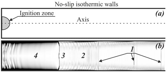
Figure 1.
(a) The problem setup and (b) a schematic of the flow structure in the channel (for schematic purposes, the channel width is shown 10 times larger than in reality). 1—Shock waves; 2—region of fresh mixture flow; 3—flame front; 4—region of combustion products.
The calculations are performed using a conventional system of conservation equations for a compressible viscous medium, accounting for diffusion, heat transfer, and chemical kinetics []. The equations are written in the cylindrical coordinate system as follows []:
where r and z are radial and axial coordinates, respectively; t is time; is density; is the k-th species’ mass fraction; p is pressure; is a mass velocity vector; is the k-th species’ diffusion velocity vector; is specific total energy; is specific inner energy; is the chemical source term; is thermal conductivity; is the diffusion coefficient of the k-th species; is the viscous stress tensor; is the enthalpy of formation of the k-th species; and is the k-th species’ molar mass.
The chemical kinetics are taken into account according to the reduced kinetic mechanism of acetylene oxidation from [], which was verified, validated and fruitfully used to solve the problem of flame propagation in a channel []. The thermodynamic and transport processes are calculated conventionally [] using data tables to supplement the utilized kinetic mechanism. The calculations are carried out via the contemporary low-dissipation technique CABARET [], which was already successfully employed for the numerical reproduction of complex flows in a reactive medium [,].
3. Results and Discussion
3.1. General Pattern of Flame Dynamics in Narrow Channel
First, let us consider the overall dynamics of a flame in a narrow channel. Depending on the mixture reactivity and heat and momentum losses to the walls of the channel, three basic scenarios can be observed (Figure 2). According to the first scenario, the flame propagates with almost permanent acceleration (this case was considered in detail recently in []). In the second case, the flame accelerates only during the early stage of “finger flame” formation and then decelerates and continues to propagate at a rather low speed, gradually slowing down due to heat losses to the channel wall []. In the third case, the initial flame development pattern is similar to the second case. The flame propagates along the channel at a rather low speed for quite a long time ( m/s or even slower). However, the situation changes drastically as soon as the spontaneous acceleration of the flame takes place after a certain period after ignition ( ms in the case of mm channel and ms in the case of mm channel, Figure 2). Next, flame acceleration leads to the DDT. The case of a 5 mm channel filled with a 51%(C2H2 + 2.5O2) + 49%N2 mixture can be treated as a critical one for which flame acceleration is still possible. Flame acceleration does not occur in mixtures more diluted with nitrogen (50%(C2H2 + 2.5O2) + 50%N2).
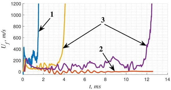
Figure 2.
The histories of flame speeds illustrate three basic scenarios of flame propagation in a narrow channel: 1—a permanently accelerating flame (75%(C2H2 + 2.5O2) + 25%N2, mm); 2—a slow flame (50%(C2H2 + 2.5O2) + 50%N2, mm); 3—a slow flame with spontaneous acceleration (51%(C2H2 + 2.5O2) + 49%N2, mm; 50%(C2H2 + 2.5O2) + 50%N2, mm).
It is well known that an important role in flame evolution in the channel is played by the evolution of the flow induced by the expanding combustion products. Hot gas expanding from the closed-end wall pushes the fresh mixture, so the flow directed along the channel walls is formed ahead of the flame front. This flow drags the flame front, causing its additional acceleration. The structure of the flow is characterized by a boundary layer that arises in the vicinity of the side wall of the channel. In turn, this flow structure causes the flame front to stretch in the boundary-layer region, which is considered the leading factor in flame acceleration []. In addition, the accelerating flame front permanently emits compression waves, distributing momentum and energy in space. This causes an additional effect on the flow development. Thus, when analyzing characteristic wave patterns (Figure 3), one can see that compression waves travel along the whole channel length, including the region of combustion products (similar visualizations can also be found in [,]). These waves interact with the flame front, causing the non-steady behavior of its propagation. One can hardly distinguish these waves in the early stages of flame propagation since their magnitude is relatively low. They propagate in the region of combustion products at a sonic speed and overcome the distance between the flame and the back-end wall rather quickly. As a result, they merely equalize the pressure behind the flame front at this stage. At the same time, as soon as the flame propagates farther from the back-end wall, these compression waves begin to interact with each other and can form weak shock waves. These shocks cause a more intense effect on the flow, and a certain degree of flame acceleration related to the shock–flame interaction can be observed. In the case of a permanently accelerating flame, such a shock-induced acceleration contributes to the overall acceleration of the flame front, causing oscillations in the flame speed in the context of permanent flame acceleration. In the case of slow flames, the flame also propagates in an oscillatory manner, and shock-induced oscillations are observed around the constant flame speed value.
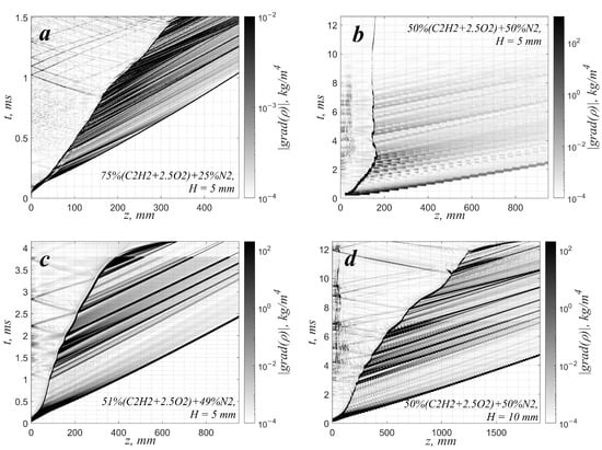
Figure 3.
Wave patterns for the cases demonstrated in Figure 2: z—coordinate along the channel wall; t—time. The grayscale palette represents the spatiotemporal evolution of the density gradient’s absolute value. (a)—75%(C2H2 + 2.5O2) + 25%N2, mm, (b)—50%(C2H2 + 2.5O2) + 50%N2, mm, (c)—51%(C2H2 + 2.5O2) + 49%N2, mm, (d)—50%(C2H2 + 2.5O2) + 50%N2, mm.
3.2. Boundary-Layer Evolution and Spontaneous Flame Acceleration
Since the flow structure formed in the channel plays an important role in the flame evolution, let us consider the evolution of the boundary layer ahead of the flame front separately. As soon as the first perturbation from the reaction zone reaches a certain cross-section of the channel, the fresh mixture in this section starts to be involved in the directed motion along the channel wall. Every subsequent compression wave overcomes the previous one, which leads to the formation of a leading shock wave. Here, the flow accelerates with the arrival of each compression wave. Figure 1b shows the schematic of the flow structure ahead of the flame front. The gas is involved in the motion along the solid surface. Therefore, a boundary layer is formed in the gap between the leading shock wave and the flame front. The evolution of the boundary layer is associated with the development of a wave like a Tollmien–Shlichting wave, in a similar way to in the shock tube reactor []. Gas-dynamic perturbations on the scale of the boundary layer transform into vortexes with a radius equal to the critical wavelength under the achieved conditions. These vortexes and their evolution can be indicated by the absolute value of vorticity (Figure 4).
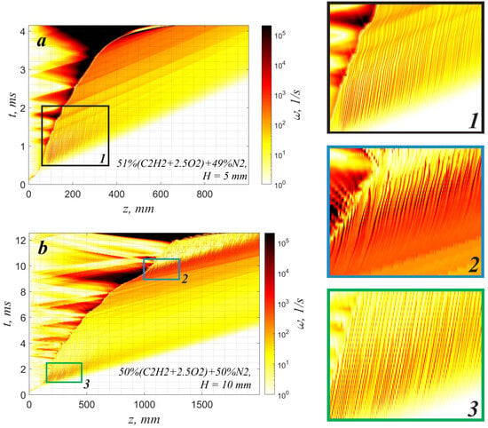
Figure 4.
Spatiotemporal evolution of the absolute value of the vorticity in the section parallel to the wall (at mm from the wall) for cases with the spontaneous acceleration of the slow flame, (a)—51%(C2H2 + 2.5O2) + 49%N2, mm, (b)—50%(C2H2 + 2.5O2) + 50%N2, mm. The same spatial and temporal scales are used in the enlarged frames ‘1’, ‘2’ and ‘3’ to the right.
Analyzing the data presented in Figure 4, one can clearly distinguish the following stages of boundary-layer evolution. First, perturbations of the boundary layer are formed at a certain distance behind the leading shock wave. Further, these perturbations evolve under the permanent impact of compression waves traveling along the channel wall. In all the presented cases, one can observe either the attenuation or neutral stability of the perturbations. Thus, the boundary layer is completely stabilized in the case of a narrow channel with a 5 mm diameter filled with a 49% nitrogen-diluted mixture (Figure 4a). The boundary layer has time to grow and occupy almost the whole channel cross-section. So, a steady velocity profile close to the Poiseuille profile is formed ahead of the flame (Figure 5a). The formed flow is stable to transverse perturbations. However, it is quite sensitive to longitudinal excitation, and as soon as the weak shock wave propagates, the flow velocity in the bulk flow increases. That leads to a certain increase in the velocity gradient across the channel, and the flame accelerates due to additional flame stretching. As one can see in Figure 2, Figure 3c, and Figure 4a, as soon as a strong shock wave appears and interacts with the flame, the apparent local flame acceleration takes place and initiates a further permanent flame velocity increase. The leading role in further flame acceleration is played by extreme flow stretching in the vicinity of the boundary layer by the shock wave. The stretching of the flow induces additional growth in the flame area and its overall acceleration, and vice versa. A positive feedback mechanism is initiated, and permanent flame acceleration is established.
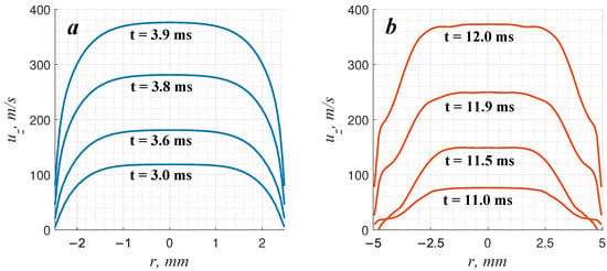
Figure 5.
Characteristic longitudinal velocity profiles ahead of the flame front for the cases with the spontaneous acceleration of the slow flame: (a)—51%(C2H2 + 2.5O2) + 49%N2, mm, (b)—50%(C2H2 + 2.5O2) + 50%N2, mm.
In the case of a wider channel (10 mm) filled with a 50% nitrogen-diluted mixture (Figure 4b), there is also an attenuation of vortex perturbations at an early stage (frame “3” in Figure 4). However, the vortex perturbations do not decay completely. This can be clearly seen in Figure 5b, where the distortion of the velocity profile in the regions of boundary layers is observed.
It is known that the shock–vortex interaction can lead to the intensification of the vortex if the intensity of the shock is sufficient []. This effect is related to the intrinsic feature of any dynamic system whereby energy is transferred from relatively coarse forcing scales to smaller ones. Here, there is an enstrophy cascade that leads to the intensification of vortexes under the shock wave impact. Exactly this scenario takes place in the considered case. As soon as a strong shock wave is formed, its interaction with vortex perturbations leads to the intensification of those vortexes (Figure 4b). Figure 6 demonstrates the time dependence of the enstrophy integrated over the gap between the leading shock and the flame. As one can see, there are spikes in the enstrophy integral related to the interaction of subsequent shock waves with a boundary layer. Such spikes reflect the energy and momentum transfer from the shock to the vortexes expended on the deformation of the vortexes, the radiation of acoustics, and the dissipation into the heat.
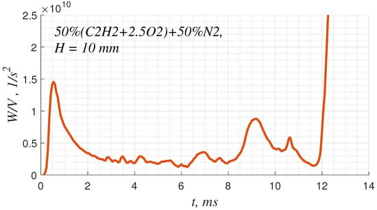
Figure 6.
Time dependence of enstrophy calculated over the gap between the leading shock and the flame.
The vortex sequence ahead of the flame front represents the additional source of flame stretching additionally amplified due to the shock-wave impact (Figure 7). The elongation of the flame front in the region of its interaction with each vortex causes a certain increase in the flame area and the burning rate. This leads to both flame acceleration and pressure buildup in the vicinity of the accelerated flame front. In turn, additional acceleration of the flow and compression leads to the intensification of the vortexes (Figure 6), so a positive feedback scenario is established again. This mechanism causes sudden flame acceleration after a relatively long period of slow propagation.
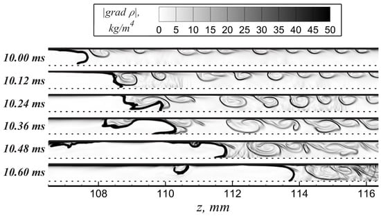
Figure 7.
Visualization of the flame–vortex street interaction.
4. Conclusions
To conclude, let us formulate the mechanism of the spontaneous acceleration of a flame in a narrow channel. The particular flame propagation mode with spontaneous acceleration is intrinsic to relatively low-reactive mixtures and is analyzed here numerically for the first time. As soon as low-reactive mixtures diluted with nitrogen are considered, the losses in narrow channels prevent the establishment of permanent flame acceleration. Under such conditions, the flame propagates at a relatively low speed for quite a long time, while significant acceleration is observed only at the late stage, directly before the transition to detonation.
As the numerical results show, key roles in flame dynamics are played by the following basic processes: (1) the generation and propagation of shock waves, (2) the development of the boundary layer, (3) shock–boundary-layer interaction, and (4) flame–boundary-layer interaction. The flow evolution remains almost the same in low- and high-reactive mixtures, despite the establishment of a low-speed flame in low-reactive mixtures. The flow of the fresh mixture is formed ahead of the flame front, while the compression waves irradiated by the reaction zone affect the flow development. The key point is the formation of the shock waves, whose interaction with the flow causes additional stretching and acceleration of the flame. The most indicative case is realized in relatively wide channels, where the perturbations of the boundary layer evolve into vortex structures. The shock–vortex street interaction causes the intensification of the vortexes. In turn, the flame interaction with an intense vortical flow leads to flame acceleration. Despite this case, the same scenario with flame acceleration takes place in narrower channels where no vortexes are observed on the scale of the boundary layer. This result confirms once again that the leading role in flame acceleration and DDT is played by the phenomenon of flame–flow interaction, and the particular structure of the flow (either it is laminar or characterized by a vortex structure on the scale of the boundary layer or it is entirely turbulent) plays only a supporting role.
The distinguished mechanism should be even more pronounced in a closed channel [], where an additional role in the flame propagation process is played by the compression waves reflected from the far-end wall of the channel. Also, the mechanism can be responsible for the formation of the “knife” flame structure observed in the toroidal reactor and reported in []. In this case, one can observe spontaneous flame acceleration along the boundary layer. This could be related to the flame interaction with the vortexes formed on the scale of the boundary layer near the outer wall of the reactor. The same mechanism can presumably be observed in open channels []. However, one should expect a much longer period of the slow-flame stage since the flow ahead of the flame front and compression waves is much weaker without a closed back end.
Author Contributions
Conceptualization, A.K.; methodology, A.K., A.Y. and I.Y.; software, I.Y.; validation, A.Y. and I.Y.; formal analysis, A.K., A.Y. and I.Y.; investigation, A.K., A.Y. and I.Y.; resources, I.Y.; data curation, A.Y. and I.Y.; writing—original draft preparation, A.K.; writing—review and editing, A.K., A.Y. and I.Y.; visualization, A.Y.; supervision, A.K.; project administration, A.K.; funding acquisition, A.K. All authors have read and agreed to the published version of the manuscript.
Funding
This research received no external funding.
Data Availability Statement
The datasets generated and/or analysed during the current study are available from the corresponding author on reasonable request.
Acknowledgments
The authors acknowledge the high-performance computing support from the Joint Supercomputer Center of the Russian Academy of Sciences.
Conflicts of Interest
The authors declare no conflicts of interest.
References
- Venetsanos, A.G.; Huld, T.; Adams, P.; Bartzis, J.G. Source, dispersion and combustion modelling of an accidental release of hydrogen in an urban environment. J. Hazard. Mater. 2003, 105, 1–25. [Google Scholar] [CrossRef]
- Wang, X.; Li, B.; Han, B.; Jin, X.; Zhang, D.; Bi, M. Explosion of high pressure hydrogen tank in fire: Mechanism, criterion, and consequence assessment. J. Energy Storage 2023, 72, 108455. [Google Scholar] [CrossRef]
- Xu, Y.; Huang, Y.; Ma, G. A review on effects of different factors on gas explosions in underground structures. Undergr. Space 2020, 5, 298–314. [Google Scholar] [CrossRef]
- International Atomic Energy Agency. Mitigation of Hydrogen Hazards in Severe Accidents in Nuclear Power Plants; Technical Report IAEA-TECDOC-1661; International Atomic Energy Agency: Vienna, Austria, 2011. [Google Scholar]
- Efremov, V.P.; Ivanov, M.F.; Kiverin, A.D.; Utkin, A.V. Shock-wave dynamics during oil-filled transformer explosions. Shock Waves 2017, 27, 517–522. [Google Scholar] [CrossRef]
- He, L.; Lee, J.H. The dynamical limit of one-dimensional detonations. Phys. Fluids 1995, 7, 1151–1158. [Google Scholar] [CrossRef]
- Zeldovich, Y. Regime classification of an exothermic reaction with nonuniform initial conditions. Combust. Flame 1980, 39, 211–214. [Google Scholar] [CrossRef]
- Kiverin, A.; Yakovenko, I. Ignition and detonation onset behind incident shock wave in the shock tube. Combust. Flame 2019, 204, 227–236. [Google Scholar] [CrossRef]
- Zel’dovich, Y.B.; Rozlovskii, A.I. On the onset of unstable normal burning: Transition of a spherical flame to detonation. Dokl. Akad. Nauk SSSR 1947, 57, 365–368. (In Russian) [Google Scholar]
- Liberman, M.A.; Ivanov, M.F.; Peil, O.E.; Valiev, D.M.; Eriksson, L.E. Self-acceleration and fractal structure of outward freely propagating flames. Phys. Fluids 2004, 16, 2476–2482. [Google Scholar] [CrossRef]
- Kiverin, A.; Yakovenko, I. Mechanism of transition to detonation in unconfined volumes. Acta Astronaut. 2020, 176, 647–652. [Google Scholar] [CrossRef]
- Clanet, C.; Searby, G. On the “tulip flame” phenomenon. Combust. Flame 1996, 105, 225–238. [Google Scholar] [CrossRef]
- Qian, C.; Liberman, M.A. On the mechanism of “tulip flame” formation: The effect of ignition sources. Phys. Fluids 2023, 35, 116122. [Google Scholar] [CrossRef]
- Yarkov, A.; Kiverin, A.; Yakovenko, I. Effect of channel geometry on the flame acceleration and transition to detonation in acetylene-oxygen-nitrogen mixtures. Acta Astronaut. 2024, 217, 273–279. [Google Scholar] [CrossRef]
- Urtiew, P.A.; Oppenheim, A.K. Experimental Observations of the Transition to Detonation in an Explosive Gas. Proc. R. Soc. London Ser. A 1966, 295, 13–28. [Google Scholar] [CrossRef]
- Kuznetsov, M.; Alekseev, V.; Matsukov, I.; Dorofeev, S. DDT in a smooth tube filled with a hydrogen–oxygen mixture. Shock Waves 2005, 14, 205–215. [Google Scholar] [CrossRef]
- Krivosheyev, P.; Novitski, A.; Penyazkov, O. Flame front dynamics, shape and structure on acceleration and deflagration-to-detonation transition. Acta Astronaut. 2023, 204, 692–704. [Google Scholar] [CrossRef]
- Wu, M.H.; Kuo, W.C. Accelerative expansion and DDT of stoichiometric ethylene/oxygen flame rings in micro-gaps. Proc. Combust. Inst. 2013, 34, 2017–2024. [Google Scholar] [CrossRef]
- Ciccarelli, G.; Johansen, C.; Kellenberger, M. High-speed flames and DDT in very rough-walled channels. Combust. Flame 2013, 160, 204–211. [Google Scholar] [CrossRef]
- Rudy, W.; Teodorczyk, A. Numerical Simulations of DDT Limits in Hydrogen-Air Mixtures in Obstacle Laden Channel. Energies 2021, 14, 24. [Google Scholar] [CrossRef]
- Shamshin, I.O.; Aksenov, V.S.; Kazachenko, M.V.; Gusev, P.A.; Frolov, S.M. Fast Deflagration-to-Detonation Transition in Helical Tubes. Processes 2023, 11, 1719. [Google Scholar] [CrossRef]
- Bivol, G.Y.; Golovastov, S.; Golub, V. Prechamber initiation of gaseous detonation in a channel. Combust. Sci. Technol. 2016, 188, 1165–1179. [Google Scholar] [CrossRef]
- Shamshin, I.O.; Kazachenko, M.V.; Frolov, S.M.; Basevich, V.Y. Deflagration-to-Detonation Transition in Stochiometric Propane–Hydrogen–Air Mixtures. Fuels 2022, 3, 667–681. [Google Scholar] [CrossRef]
- Kuznetsov, M.; Denkevits, A.; Veser, A.; Friedrich, A. Flame propagation regimes and critical conditions for flame acceleration and detonation transition for hydrogen-air mixtures at cryogenic temperatures. Int. J. Hydrogen Energy 2022, 47, 30743–30756. [Google Scholar] [CrossRef]
- Johansen, C.; Ciccarelli, G. Numerical simulations of the flow field ahead of an accelerating flame in an obstructed channel. Combust. Theory Model. 2010, 14, 235–255. [Google Scholar] [CrossRef]
- Boeck, L.; Lapointe, S.; Melguizo-Gavilanes, J.; Ciccarelli, G. Flame propagation across an obstacle: OH-PLIF and 2-D simulations with detailed chemistry. Proc. Combust. Inst. 2017, 36, 2799–2806. [Google Scholar] [CrossRef]
- Smirnov, N.; Nikitin, V.; Phylippov, Y.G. Deflagration-to-detonation transition in gases in tubes with cavities. J. Eng. Phys. Thermophys. 2010, 83, 1287–1316. [Google Scholar] [CrossRef]
- Cross, M.; Ciccarelli, G. DDT and detonation propagation limits in an obstacle filled tube. J. Loss Prev. Process. Ind. 2015, 36, 380–386. [Google Scholar] [CrossRef]
- Ivanov, M.; Kiverin, A.; Liberman, M. Hydrogen-oxygen flame acceleration and transition to detonation in channels with no-slip walls for a detailed chemical reaction model. Phys. Rev. E 2011, 83, 056313. [Google Scholar] [CrossRef]
- Smirnov, N.N.; Tyurnikov, M.V. Experimental investigation of deflagration to detonation transition in hydrocarbon-air gaseous mixtures. Combust. Flame 1995, 100, 661–668. [Google Scholar] [CrossRef]
- Thomas, G.; Ward, S.; Williams, R.; Bambrey, R. On critical conditions for detonation initiation by shock reflection from obstacles. Shock Waves 2002, 12, 111–119. [Google Scholar] [CrossRef]
- Medvedev, S.P.; Polenov, A.N.; Khomik, S.V.; Gel’fand, B.E. Deflagration-to-detonation transition in air-binary fuel mixtures in an obstacle-laden channel. Russ. J. Phys. Chem. B 2010, 4, 70–74. [Google Scholar] [CrossRef]
- Kiverin, A.D.; Yakovenko, I.S. Estimation of critical conditions for deflagration-to-detonation transition in obstructed channels filled with gaseous mixtures. Math. Model. Nat. Phenom. 2018, 13, 54. [Google Scholar] [CrossRef]
- Rakotoarison, W.; Vilende, Y.; Pekalski, A.; Radulescu, M.I. Model for Chapman-Jouguet deflagrations in open ended tubes with varying vent ratios. Combust. Flame 2024, 260, 113212. [Google Scholar] [CrossRef]
- Wang, C.; Wu, S.; Zhao, Y.; Addai, E.K. Experimental investigation on explosion flame propagation of H2-O2 in a small scale pipeline. J. Loss Prev. Process. Ind. 2017, 49, 612–619. [Google Scholar] [CrossRef]
- Bykov, V.; Koksharov, A.; Kuznetsov, M.; Zhukov, V. Hydrogen-oxygen flame acceleration in narrow open ended channels. Combust. Flame 2022, 238, 111913. [Google Scholar] [CrossRef]
- Kuo, K.K.; Acharya, R. Fundamentals of Turbulent and Multiphase Combustion, 1st ed.; John Wiley & Sons, Inc.: Hoboken, NJ, USA, 2012. [Google Scholar]
- Kiverin, A.; Yarkov, A.; Yakovenko, I. On the Features of Numerical Simulation of Hydrogen Self-Ignition under High-Pressure Release. Computation 2024, 12, 103. [Google Scholar] [CrossRef]
- Varatharajan, B.; Williams, F. Chemical-kinetic descriptions of high-temperature ignition and detonation of acetylene-oxygen-diluent systems. Combust. Flame 2001, 124, 624–645. [Google Scholar] [CrossRef]
- McBridge, B.; Gordon, S.; Reno, M. Coefficients for calculating thermodynamic and transport properties of individual species. In NASA Technical Memorandum; NASA Langley Research Center: Hampton, VA, USA, 1993; Volume 4513. [Google Scholar]
- Karabasov, S.A.; Goloviznin, V.M. Compact Accurately Boundary-Adjusting high-REsolution Technique for fluid dynamics. J. Comput. Phys. 2009, 228, 7426–7451. [Google Scholar] [CrossRef]
- Yakovenko, I.; Kiverin, A. Numerical Modeling of Hydrogen Combustion: Approaches and Benchmarks. Fire 2023, 6, 239. [Google Scholar] [CrossRef]
- Han, W.; Huang, J.; Gu, G.; Wang, C.; Law, C.K. Surface heat loss and chemical kinetic response in deflagration-to-detonation transition in microchannels. Phys. Rev. Fluids 2020, 5, 053201. [Google Scholar] [CrossRef]
- Kurylo, J.; Dwyer, H.A.; Oppenheim, A.K. Numerical Analysis of Flowfields Generated by Accelerating Flames. AIAA J. 1980, 18, 302–308. [Google Scholar] [CrossRef][Green Version]
- Deshaies, B.; Joulin, G. Flame-speed sensitivity to temperature changes and the deflagration-to-detonation transition. Combust. Flame 1989, 77, 201–212. [Google Scholar] [CrossRef]
- Kiverin, A.D.; Yakovenko, I.S. Evolution of wave patterns and temperature field in shock-tube flow. Phys. Rev. Fluids 2018, 3, 053201. [Google Scholar] [CrossRef]
- Ellzey, J.L.; Picone, M.; Oran, E.S. The Interaction of a Shock with a Compressible Vortex; Naval Research Laboratory, Senior Science for Reactive Flow Physics Branch: Washington, DC, USA, 1992. [Google Scholar]
- Kuznetsov, M.; Yanez, J.; Grune, J. Flame acceleration and DDT in a torus geometry. In Proceedings of the 30th International Symposium on Shock Waves 1: ISSW30-Volume 1, Tel-Aviv, Israel, 19–24 July 2015; Springer: Berlin/Heidelberg, Germany, 2017; pp. 385–389. [Google Scholar]
Disclaimer/Publisher’s Note: The statements, opinions and data contained in all publications are solely those of the individual author(s) and contributor(s) and not of MDPI and/or the editor(s). MDPI and/or the editor(s) disclaim responsibility for any injury to people or property resulting from any ideas, methods, instructions or products referred to in the content. |
© 2024 by the authors. Licensee MDPI, Basel, Switzerland. This article is an open access article distributed under the terms and conditions of the Creative Commons Attribution (CC BY) license (https://creativecommons.org/licenses/by/4.0/).