Abstract
The depletion of fossil-based fuels, fluctuating fuel market, and environmental deterioration demand an aggressive approach towards the advancement of renewable energy technologies. By the time reliable technology for a clean and abundant energy supply is established, existing sources must be economized. Biomass gasification is the way forward in that direction. CFD modeling shows promise in the development of advanced gasification systems. A simplified 3D CFD model of a downdraft gasifier is developed to investigate the effect of gasifying agent composition on the quality of syngas. Simulation results are compared with published experimental data and found to be in reasonably good agreement. Mixing CO2 with a gasification agent is also investigated as a possible carbon capture and utilization (CCU) strategy. An air-steam mixture is used as a base-case gasification agent. Firstly, the effect of air-to-steam ratio on syngas composition is investigated. Secondly, the effect of oxygen and mixing CO2 with a gasification agent is investigated in two separate cases. A 50%-50% air-steam mixture is found to produce the best quality syngas. Oxygen is found to have a negligible impact on the quality of syngas. The air-steam-CO2 = 23%-50%-15% mixture is found to be optimum regarding syngas quality.
1. Introduction
The rapid depletion of natural resources warrants the development of parallel and sustainable technologies to meet the energy needs of the growing world population. The shift of the global energy sector towards renewable energy sources should be regarded as a timely step in the right direction. Environmental deterioration associated with the consumption of conventional fossil fuels is another driving factor behind the growing research and development activities in the renewable energy sector essential for sustaining fuel availability for future generations [1,2,3]. These factors bring a realization amongst world communities of the need to opt for renewable fuels like biomass that can provide ample energy with little environmental impact [4,5,6,7]. Biomass is constituted by plant- and animal-based organic matter. Industrial wood waste like wood scrap, sawdust, and crop waste contains abundant chemical energy. In addition, dried wood waste from trees is another source of stored chemical energy. Many recent wildfires have been attributed to the self-ignition of dried bush and tree wood. Hence, part of the dried wood must be removed from the forests and the wild in a sustainable way, with new trees being planted [8,9,10,11]. Chemical energy stored in the biomass can be harnessed in different ways. The most common method to obtain energy from biomass is combustion [12,13,14,15]. Biomass could effectively be converted into a variety of other fuels through gasification. Syngas produced through the gasification process can be used as a fuel that is cleaner compared to that produced from the direct combustion of biomass. Syngas can also be used as a building block for chemical synthesis [16,17,18]. Furthermore, residues could be used as biochar [19,20] or further upgraded for use as sorbents [21,22,23]. The majority of countries, with the exception of those dominating in hydropower, are observing an increased trend in the use of bioenergy derived from biomass, which constitutes more than half of the energy supply [24].
Gasification is a thermochemical process that converts solid organic matter into gaseous fuels in a limited oxygen environment. It is a partial oxidation process that converts the solid mass into producer gas consisting mainly of CO, H2, CO2, H2O, and CH4, as well as N2 in the case when air is used as a gasifying agent along with particulate matter and tars [25,26]. After cleaning, producer gas can be used directly as fuel in internal combustion engines (ICEs) and gas turbines or for reforming and subsequent synthesis of chemicals, depending on its purity and tar content [27]. If plant, wood, or animal waste is used as fuel, the process is referred to as biomass gasification. The producer gas composition depends mainly on the type of biomass as well as gasifying agents and operating conditions used [28,29]. CO2 could be used as a gasifying agent. Using CO2 as a gasifying agent results in endothermic reactions with slower kinetics. Nonetheless, CO2 gasification can be implemented as a carbon capture and utilization (CCU) technology [30,31,32,33].
The parameter and design optimization of a downdraft gasifier plays an important role in increasing the yield of producer gas. However, designing and commissioning commercial gasifiers of varying sizes and specifications for optimum syngas production requires a lot of resources [34]. Moreover, detailed knowledge about the producer gas composition is critical for the safe operation of the gasifier [35,36,37]. For an efficient gasifier design, prior knowledge about the influence of different design and operation parameters on the quality of product gases is essential.
The most commonly used models to simulate the gasification process include thermodynamic equilibrium models [38,39,40,41,42,43] and kinetic models [44,45,46,47,48]. Thermodynamic equilibrium models do not include the geometrical dimensions of the gasifier and, hence, are unable to capture spatial variations in temperature and composition. Moreover, these models assume a complete conversion of char into syngas. Although kinetic models are able to capture variations along the gasifier length, they still have limitations in distinguishing between different zones (i.e., pyrolysis, oxidation, and reduction) [45]. In addition to equilibrium and kinetic models, a few other combined or hybrid models have also been used to simulate gasifiers, i.e., process models utilizing equilibrium [49], quasi-equilibrium, or kinetic models, as well as artificial neural networks (ANN) [45]. With the advancement of computing technology and numerical techniques, CFD has become a preferred choice for modeling engineers and scientists [50,51]. CFD enjoys several advantages over the other modeling approaches used to simulate the gasification process. It incorporates multiphysics phenomena like heat and mass transfer, fluid flow, and reaction kinetics, thereby solving the corresponding equation simultaneously [52]. Furthermore, spatial variations in process parameters, e.g., temperature and compositions, can better be captured in CFD through contour, vector, and line plots across the gasifier domain. Hence, CFD makes it possible to accurately predict the influence of variations in geometrical configurations on the performance of the gasifier [53].
While numerous CFD studies focus on the design considerations by optimizing geometric parameters, the process parameters like velocity, temperature, and gasifying agent compositions have also been investigated using CFD modeling and simulations [34,44].
It is clear from the literature cited above that thermodynamic equilibrium models [38,39,40,41,42,43] have limitations in fully capturing variations in temperature and gas compositions across the gasifier domain. Kinetic models [44,45,46,47,48] fail to distinguish between different zones within the gasifier. Most of the CFD models reported in previously published literature are restricted to a 2D level [34,54,55,56,57,58,59,60] due to the low computational cost of these models. The 2D models do not account for the circumferential flow of the fluid as well as the flow field at the wall boundaries of the gasifier. Flow hydrodynamics are significantly affected by the large surface area of the walls, which is not accounted for in 2D CFD models. CFD models with higher dimensionality (i.e., 3D) incorporating comprehensive physical properties and detailed chemistry [34,60,61,62] are often too complex and computationally expensive. These models use the Eulerian-Lagrangian approach that treats the solid carbon as individual particles, thereby rendering the CFD computations complex and computationally intensive. To establish a balance between model complexity and accuracy of the model predictions, 3D CFD models can be optimized for computational cost by using simpler sub-models along with realistic assumptions. Moreover, intelligent choice of grid size could also render the computational cost of 3D CFD models manageable. Another important factor that strongly influences the accuracy and computational cost of CFD models, especially those with higher dimensionality, is the choice of kinetic model. Kinetic models for combustion and gasification are complex and mostly encrypted due to the proprietary nature of these models. Hence, finding a suitable kinetic model for 3D CFD simulations with reasonably low complexity is a challenge. Kinetic parameters like pre-exponential factor and activation energy greatly vary within the kinetic models used in different previously published CFD studies.
In the present work, a 3D CFD model of a downdraft gasifier is developed with a simpler species transport model assuming homogeneous reaction kinetics rather than solid phase heterogeneous kinetics. A simpler Eulerian-Eulerian approach is used that allows the solid carbon particles and volatiles to be treated as an interpenetrating dispersed gas phase. Computations are further simplified by using a finite-rate/eddy-dissipation sub-model to model turbulence-chemistry interaction where reactions are limited by mixing rather than chemical kinetics. Reaction chemistry and kinetic parameters are selected in a way that minimizes computational load without compromising accuracy. The present model is a simplified 3D CFD model implemented into a commercial CFD package (ANSYS Fluent) that can be used for the design and optimization of the selected gasifier type. Hence, the present study would be a valuable addition to the knowledge base for the research and development of gasification systems.
This study is aimed at developing a simplified 3D CFD model to investigate the effect of the inlet composition of the gasifying agent and air-to-steam ratio on the outlet gas composition. Furthermore, the effect of mixing CO2 with the gasifying agent is also investigated as a possible carbon capture and utilization (CCU) strategy.
2. Materials and Methods
2.1. Geometry Model and Domain Discretization
The three-dimensional geometry domain of the downdraft gasifier was developed using the Ansys Design Modeler. The internal diameter of the gasifier is 20 cm, while the total length is 55 cm. The location of the air inlet, producer gas outlet, and other design parameters were adopted from [63]. A schematic of the gasifier is shown in Figure 1, including different zones, including pyrolysis, partial oxidation, and reduction zones. Biomass is fed from the top of the gasifier while the gasifying agent is introduced through 4 inlet nozzles located above the throat of the gasifier. The constriction or throat below the gasifier inlet nozzles is referred to as the Imbert in such gasifier designs. The constriction plays an important role as it increases the residence time of volatiles and tar in the high-temperature zones, leading to tar cracking reactions resulting in cleaner syngas with higher yields [34]. The product gases leave the gasifier just below the reduction zone, where ash drops to the bottom of the gasifier.
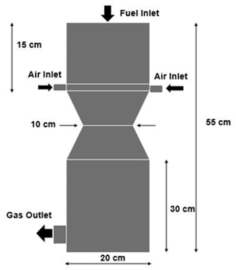
Figure 1.
Geometry of the downdraft gasifier used in the study.
The 3D domain is discretized using tetrahedral finite volume (FV) elements, as shown in Figure 2. Selective element size and resolution are adopted where smaller regions have smaller element sizes with denser grids and vice versa. This selective mesh sizing strategy significantly saves computational effort, thereby capturing variations within the regions of interest. Mesh size is optimized using a grid independence test, which involves carrying out simulations at different element sizes, and selected parameters like outlet gas mole fractions are recorded. The mesh size corresponding to uniform mole fractions is selected for detailed simulations and further analysis. Different mesh sizes used in the grid independence test are shown in Figure 3.
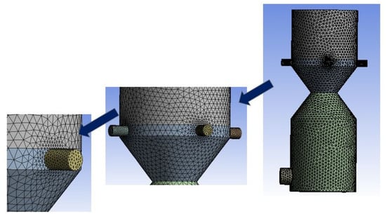
Figure 2.
Discretization of the downdraft gasifier domain using tetrahedral elements.
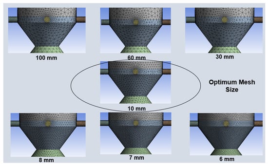
Figure 3.
Different mesh sizes used in the grid size independence test.
Mesh independence test results are presented in graphical form in Figure 4. The mesh independence test was performed at different mesh sizes ranging from 100 mm to 6 mm. The graph is plotted for the mole fraction of outlet gas components as a function of mesh size. It is evident from Figure 4 that at 10 mm size, mole fractions almost reach a steady state, indicating grid independence. Hence, a mesh size of 10 mm with 101,230 elements is considered the optimum and selected for subsequent simulations and analysis.
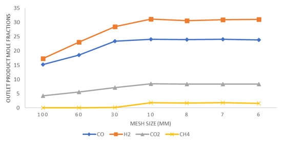
Figure 4.
Mole fractions of outlet gas species plotted versus mesh size.
2.2. Mathematical Model
2.2.1. Model Assumptions
Assumptions are very important in maintaining a balance between the accuracy of the model predictions and model simplifications, which directly impact the computational cost of the simulations. In the present work, the following carefully thought-out assumptions are made:
- The gasifier is treated as a steady flow system.
- Flow inside the gasification chamber is incompressible.
- Substances higher than methane (CH4), i.e., ethane, propane, and butane, are excluded from the model.
- The pyrolysis reaction is assumed to be fully completed: This assumption implies that the biomass is completely converted into char and volatiles, thus eliminating the need to model the complex kinetics of the pyrolysis process.
- Char is assumed to be fixed carbon homogeneously mixed with volatiles and approximated as part of the gas phase.
- Adiabatic and no-slip conditions are assumed on the gasifier walls.
- Homogeneous gas phase kinetics are assumed with a species transport sub-model along with the standard k-e model for turbulent gas phase kinetics.
- The Eulerian-Eulerian approach is used, which allows for the tracking of species concentrations over time within the turbulent gas phase. This approach treats the gas phase as a continuous interconnected medium, thereby significantly shedding the computational burden.
2.2.2. Governing Equations
The present model is based on mass, energy, and momentum conservation laws and incorporates species transport, including turbulent and dissipating kinetic energy equations. These equations are solved numerically for the steady state with turbulent flow conditions and finite-rate/eddy-dissipation reaction kinetics.
The mass conservation equation is usually the continuity equation, which is written as follows:
The energy conservation equation is used to obtain the temperature field across the domain.
The left-hand side of the equation represents heat flux according to Fourier’s law of heat conduction, incorporating species diffusion and viscous dissipation at normal shear stress. Overall, the equation shows that total heat flux is equal to the sum of internal energy and heat added by the heat source.
The momentum conservation equation is based on Newton’s law of motion and is given as follows:
Considering the species transport model for CFD simulations, the turbulent k-ε model is the most accurate model in terms of flow simulations. It is a semi-empirical model and involves turbulent as well as dissipation kinetic energy. The transport equations are given as follows:
Species transport
Turbulent kinetic energy
Dissipation kinetic energy
2.3. Reaction Chemistry and Kinetic Model Applicable to a Downdraft Gasifier
Reaction kinetics is divided into three zones, namely pyrolysis, oxidation, and reduction zones. The pyrolysis reaction kinetics is complex, as it involves a large set of reactions [64], the exact number and chemistry of which is still unknown [65]. Some of these reactions generate tars with a complex mixture of hydrocarbons, including single and multiple-ringed aromatic hydrocarbons. To avoid complexity, a global single reaction mechanism is widely accepted to model pyrolysis reactions. This mechanism assumes that all the hydrocarbons, including tars, are immediately converted into char and volatiles (CO, CO2, H2, H2O, CH4).
The next zone is the partial oxidation zone, where incomplete combustion takes place. The reactions are exothermic, which generates heat that is used to some extent to further break down tar content by thermal cracking. In CFD modeling, this approach is very useful, where tar cracking after the pyrolysis zone results in a relatively low tar content. This is one of the main benefits of downdraft gasifiers, as they produce cleaner producer gas in comparison to updraft gasifiers. The reactions within the oxidation zone occur at temperatures ranging from 1300 K to 1700 K [66].
Moving down the throat of the downdraft gasifier comes the reduction zone, where gases coming from pyrolysis and oxidation zones undergo reduction at the temperature range of 900–1300 K. Gases are converted into non-condensable gaseous components, mainly CO, CO2, H2, and CH4. These reactions are mainly endothermic and modeled as homogeneous gas phase reactions in order to reduce the model’s complexity. Chemical reactions constituting the kinetic model used in the present work, along with kinetic parameters, are presented in Table 1 below.

Table 1.
Chemical reactions and kinetic model along with kinetic parameters.
2.4. Boundary Conditions and Solution Methods
It was assumed in the simulation model that wood residues were fed from the top of the gasifier. The proximate and ultimate analysis of wood residues is given in Table 2 below.

Table 2.
Characterization of wood residues (biomass) used in the present study [63].
In order to accurately simulate the gasification process, it is important to define the boundary conditions at three key locations: the fuel inlet, the air (oxidizer) inlet, and the gas outlet. At the air (oxidizer) inlet, a velocity of 1.73 m/s is specified, with gases entering at a temperature of 350 K. At the fuel (biomass) inlet, a mass flow rate of 2.77 × 10⁻⁴ kg·s−1 is used, with fuel entering at a temperature of 400 K. These parameters dictate the flow of air and biomass into the system, playing a significant role in the overall gasification process. Finally, at the gas outlet, a pressure outlet condition of 0 Pa is used, ensuring that the produced gases exit the system without restriction.
2.5. Model Validation
Simulation results are compared with results from a previously developed model [68] and found to be in good agreement (Figure 5).
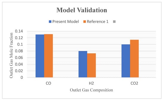
Figure 5.
Graph of model validation—comparison with previously published work (Reference 1 in the figure refers to Azlan et al. 2021 [68]).
The model has also been compared with a number of previous works [34,55,69,70] against its temperature profile along the length of the gasifier and found to be in reasonably good agreement with temperature profiles of pilot scale and modeled gasifiers. Temperature contours across the plane of the gasifier along with a line plot across the gasifier length are shown in Figure 6 below.
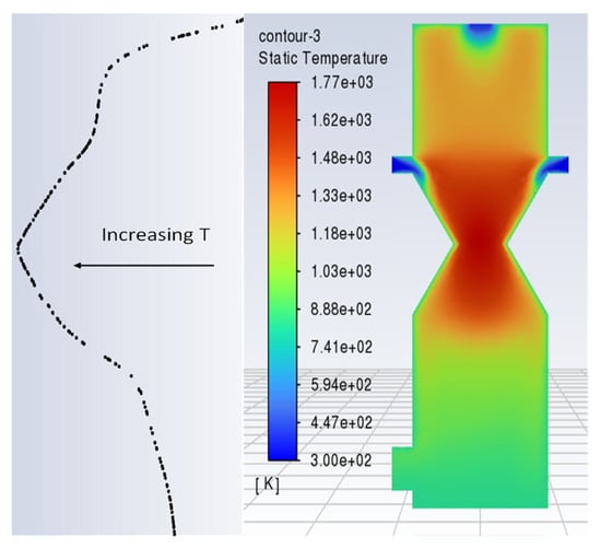
Figure 6.
Temperature profile along the length of gasifier.
3. Results and Discussions
The main objective of the present research is to study the effect of variation in the inlet composition of the oxidizing agent by changing the air-to-steam ratio and its effect on the product gas composition. After optimizing the inlet composition of gasification agents, CO2 was introduced to the air-steam mixture to study its effect on the outlet gas composition. Recent research on a pilot scale downdraft gasifier [53] presented results of a numerical model investigation using Aspen Plus, along with experimental studies. The experimental result of their research shows an H2 content of 12.72% and a CO content of 17.03%, which can be compared with the presented results below. Bhoopendra Pandey’s [71] research on air-CO2 gasification comes in good agreement with the presented results of the effect of adding CO2 in the gasifying agent.
3.1. Effect of Air-Steam Ratio
Within the scope of this work, the effect of air-to-steam ratio was studied using three cases, i.e., steam = 0%, 50%, and 100%.
- Case 1: Air-Steam = 100%-0%
- Case 2: Air-Steam = 50%-50%
- Case 3: Air-Steam = 0%-100%
Steam introduced at the inlet is primarily saturated steam at 373 K, slightly above the boundary value, i.e., 350 K, to affect immediate gasification and avoid water formation. It is clear from the results that hydrogen production is increased as the steam fraction at the air inlet increases. From the point of view of the model, this could be attributed to the water gas shift reaction as well as the steam reforming of methane. Similarly, CO2 and CO production is maximum at 0% steam and gradually decreases as the percentage of steam increases due to the increased rate of oxidation reactions. Figure 7 shows that as the percentage of air is decreased in the gasifying agent, more CO is produced in the gasification zone and vice versa. This can be explained by a higher tendency of exothermic oxidation reactions in the gasification zone, causing a drop in CO production. CO formation is comparable for both the other two cases, i.e., air-steam = 50%-50% and air-steam = 0%-100%. This shows that case 2, i.e., air-steam = 50%-50%, favors CO production and is hence regarded as the optimum.
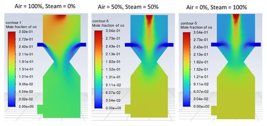
Figure 7.
Contours of mole fraction of CO with different air steam ratios.
Figure 8 indicates that with 100% air, hydrogen production is lower and non-uniformly distributed within the reduction zone as compared with case 2 (air-steam = 50%-50%), where more hydrogen is formed with uniform distribution. In case 3 (air-steam = 0%-100%), H2 production increases further than in case 2, but it negatively impacts outlet gas temperature and composition. Using 100% steam causes the temperature of the gasification zone to drop, and thus less energy will be available to crack the tars, resulting in incomplete tar production. Thus, the product gas would have a higher tar content and would not be considered the cleaner fuel as expected from a downdraft gasifier. Hence, in terms of cleaner hydrogen production, again, case 2 is regarded as the optimum. Looking at the contours of CO2 in Figure 9, it can be noticed that increasing air fraction in the gasifying agent results in the formation of more CO2, which indicates the reaction tendency towards combustion rather than gasification. Figure 10 also supports the trends observed in Figure 7, Figure 8 and Figure 9 that the optimum case in terms of quality of the product gas is found to be case 2, i.e., air-steam = 50%-50%.
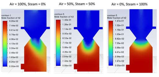
Figure 8.
Contours of mole fraction of H2 with different air steam ratios.
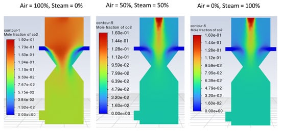
Figure 9.
Contours of mole fraction of CO2 with different air-steam ratios.
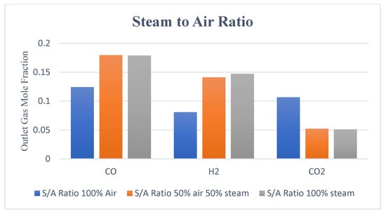
Figure 10.
Outlet gas composition with different air-steam ratios.
3.2. Effect of Using O2 Enriched Air
In this case, O2-enriched air with varying fractions (23%, 35%, and 50%) of oxygen was used as a gasifying agent.
- Case 1: O2-N2 (air) = 23%-77%
- Case 2: O2-N2 (air) = 35%-65%
- Case 3: O2-N2 (air) = 50%-50%
No significant change in the outlet gas composition was observed by increasing the O2 fraction in the air, as indicated by Figure 11, Figure 12 and Figure 13. However, using enriched air would add to the cost and have an increased tendency of CO and CO2 formation as compared to H2 due to the increased rate of oxidation with higher oxygen in the gasifying agent. Contours of CO, H2, and CO2 are shown in Figure 11, Figure 12 and Figure 13, respectively, with different O2 fractions in the air. The bar chart in Figure 14 indicates the same trend as observed in the contour plots above (Figure 11, Figure 12 and Figure 13).
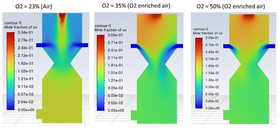
Figure 11.
Contours of mole fraction of CO with O2-enriched air as a gasifying agent.
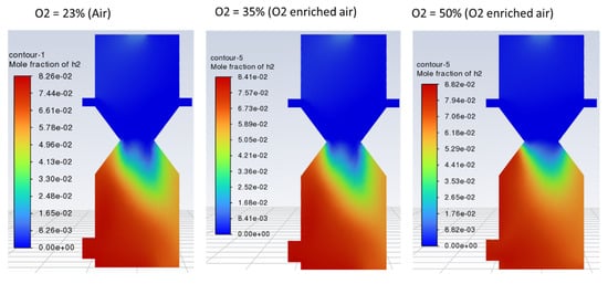
Figure 12.
Contours of mole fraction of H2 with O2-enriched air as a gasifying agent.
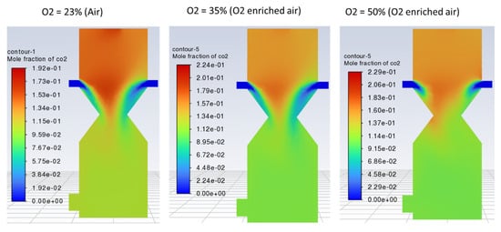
Figure 13.
Contours of mole fraction of CO2 with O2-enriched air.
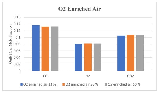
Figure 14.
Outlet gas composition with O2-enriched air used as a gasifying agent.
3.3. Effect of Using CO2 with Air-Stream Mixture
Three cases are considered to study the effect of CO2 present in the gasification agent:
- Case 1: Air-Steam-CO2 = 23%-50%-0%
- Case 2: Air-Steam-CO2 = 23%-50%-15%
- Case 3: Air-Steam-CO2 = 23%-50%-30%
Results show that in all three cases, variation in CO and H2 mole fractions within the gasifier and at the outlet is not significant compared to that of the CO2. These small variations are difficult to observe and analyzed through contour plots. Hence, contour plots are not presented. The analysis is carried out through the bar charts presented in Figure 15 below. It illustrates the outlet gas composition obtained by varying the percentage of CO2 mole fraction in the oxidizer inlet. The highest yield of combustible compounds in syngas is achieved in case 2, where CO2 in the gasification agent is 15%. In case 2, outlet gas composition is comparable to that achieved when the air-steam mixture alone is used as a gasifying agent. This indicates that 15% CO2 with 23%-50% air-steam mixture gives the optimum yield of the combustible compounds in syngas. However, the charts also show that using a higher percentage of CO2 in the gasifying agent leads to an increase in CO2 content in the outlet gas. This can be explained by the fact that a significant portion of the carbon is not effectively converted into valuable gases and ends up as CO2 in the product gas stream.
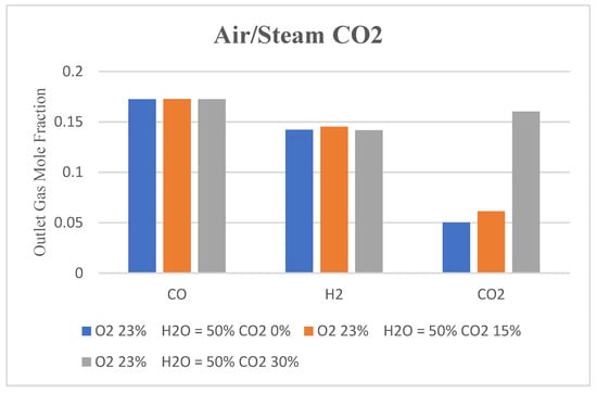
Figure 15.
Bar chart showing outlet gas composition with CO2 added to air-steam mixture as a gasifying agent.
The introduction of CO2 along with the air-steam mixture causes a reduction in the amount of air and hence nitrogen in the gasifying agent, leading to a higher concentration of hydrogen and carbon monoxide in the syngas. This results in a higher heating value of the syngas, which is beneficial for certain applications. Furthermore, CO2 also suppresses tar formation, which is beneficial since tar causes clogging of the equipment and a reduction in the efficiency of the gasifier. CO2 in the air-steam mixture results in a higher temperature in the gasifier, which further enhances gasification efficiency and reduces tar formation due to thermal cracking. Most importantly, mixing CO2 with gasifying agents opens research pathways for CO2 sequestration from the environment, thus contributing to the remediation of global warming. A major drawback of CO2 mixing is the quality degradation of syngas due to the presence of higher amounts of CO2. This could be remedied by the incorporation of recirculation.
4. Conclusions
A simplified and moderately computation-intensive 3D CFD model was used in the present work to simulate and optimize the effect of gasifying agent composition. Simulation results were validated with previously published numerical models and found to be in reasonably good agreement. A gasifying agent consisting of 50% air and 50% steam (air-steam = 50%-50%) favored CO production. Using 100% steam caused the temperature of the gasification zone to drop significantly, which could potentially impact syngas tar content. For simulations using mixtures of O2 and air, no significant change in the syngas composition was observed by increasing the O2 mass fraction in the air. Hence, O2 enrichment of air does not have a significant impact on the quality of syngas produced. Simulation results indicate that 15% CO2 with a 23%-50% air-steam mixture, i.e., case 2, gives an optimum yield of combustible compounds in syngas. Results show that using a higher percentage of CO2 in the gasification agent leads to an increase in CO2 content in the outlet gas. A major drawback of CO2 mixing is the quality degradation of syngas due to the presence of higher amounts of CO2. This could be remedied by recycling a part of the gas stream.
Improvement of the developed CFD model through customization using user-defined functions (UDFs) and kinetic model refinement is recommended. Nonetheless, CO2 mixing during biomass gasification could be used in the future as the CCU technology. Moreover, it seems sensible to recommend further investigation of the prospects of CO2 mixing as a feasible CCU technology, taking into account the complete value chain.
Author Contributions
Conceptualization, A.M., M.W.T., M.A.S. and M.Y.A.; methodology, A.M., M.W.T., M.Y.A. and L.N.; software, A.M., M.W.T. and M.Y.A.; validation, M.A.S., M.Y.A. and J.M.; formal analysis, A.M., M.W.T., M.A.S. and M.Y.A.; investigation, M.W.T., M.A.S., M.Y.A. and J.M.; resources, M.W.T., M.A.S. and H.H.; data curation, A.M., M.A.S., M.Y.A., H.H. and J.M.; writing—original draft preparation, A.M., M.W.T., M.A.S. and M.Y.A.; writing—review and editing, M.W.T., M.Y.A., J.M. and L.N.; visualization, A.M., M.W.T., M.A.S. and H.H.; supervision, M.W.T., M.A.S., M.Y.A. and J.M.; project administration, M.W.T., M.A.S., M.Y.A. and L.N. All authors have read and agreed to the published version of the manuscript.
Funding
This research received no external funding.
Institutional Review Board Statement
Not applicable.
Informed Consent Statement
Not applicable.
Data Availability Statement
Data available on request.
Conflicts of Interest
The authors declare no conflict of interest.
Nomenclature
| xi, xj | Direction vector | - |
| ui, uj | Velocity vector | m·s−1 |
| Pressure | Pa | |
| Stress tensor | Pa | |
| Gravitational force | m·s−2 | |
| Mass force | N | |
| Enthalpy | J·kg−1 | |
| Thermal conductivity | W·m−1 K−1 | |
| Avg. Specific heat | J·kg−1 K−1 | |
| Heat source term | W·m−3 | |
| Turbulent Viscosity | Pa·s | |
| Turbulent Prandtl number for k | - | |
| k | Turbulence kinetic energy | m2·s−2 |
| Generation of turbulence kinetic energy | m2·s−2 | |
| Dissipation turbulence kinetic energy | m2·s−3 | |
| Turbulent Prandtl number for | - | |
| , | Constants | - |
References
- Oyedeji, O.A. Understanding and Modeling the Formation of Syngas Contaminants during Biomass Gasification. Ph.D. Thesis, University of Tennessee, Knoxville, TN, USA, 2019; pp. 1–216. [Google Scholar]
- Saleem, F.; Abbas, A.; Rehman, A.; Khoja, A.H.; Naqvi, S.R.; Arshad, M.Y.; Zhang, K.; Harvey, A. Decomposition of Benzene as a Biomass Gasification Tar in CH4 Carrier Gas Using Non-Thermal Plasma: Parametric and Kinetic Study. J. Energy Inst. 2022, 102, 190–195. [Google Scholar] [CrossRef]
- Gul, H.; Arshad, M.Y.; Tahir, M.W. Production of H2 via Sorption Enhanced Auto-Thermal Reforming for Small Scale Applications-A Process Modeling and Machine Learning Study. Int. J. Hydrogen Energy 2023, 48, 12622–12635. [Google Scholar] [CrossRef]
- Salem, A.M.; Paul, M.C. CFD Modelling of Spatiotemporal Evolution of Detailed Tar Species in a Downdraft Gasifier. Biomass Bioenergy 2023, 168, 106656. [Google Scholar] [CrossRef]
- Saeed, M.A.; Niedzwiecki, L.; Arshad, M.Y.; Skrinsky, J.; Andrews, G.E.; Phylaktou, H.N. Combustion and Explosion Characteristics of Pulverised Wood, Valorized with Mild Pyrolysis in Pilot Scale Installation, Using the Modified ISO 1 M3 Dust Explosion Vessel. Appl. Sci. 2022, 12, 12928. [Google Scholar] [CrossRef]
- Yar, A.; Arshad, M.Y.; Asghar, F.; Amjad, W.; Asghar, F.; Hussain, M.I.; Lee, G.H.; Mahmood, F. Machine Learning-Based Relative Performance Analysis of Monocrystalline and Polycrystalline Grid-Tied PV Systems. Int. J. Photoenergy 2022, 2022, 3186378. [Google Scholar] [CrossRef]
- Yousaf, A.M.; Aqsa, R. Integrating Circular Economy, SBTI, Digital LCA, and ESG Benchmarks for Sustainable Textile Dyeing: A Critical Review of Industrial Textile Practices. Glob. NEST J. 2023, 25, 39–51. [Google Scholar] [CrossRef]
- Nunes, L.; Raposo, M.; Meireles, C.; Gomes, C.; Ribeiro, N. Energy Recovery of Shrub Species as a Path to Reduce the Risk of Occurrence of Rural Fires: A Case Study in Serra Da Estrela Natural Park (Portugal). Fire 2021, 4, 33. [Google Scholar] [CrossRef]
- Kalogiannidis, S.; Chatzitheodoridis, F.; Kalfas, D.; Patitsa, C.; Papagrigoriou, A. Socio-Psychological, Economic and Environmental Effects of Forest Fires. Fire 2023, 6, 280. [Google Scholar] [CrossRef]
- Moriarty, K.; Cheng, A.S.; Hoffman, C.M.; Cottrell, S.P.; Alexander, M.E. Firefighter Observations of “Surprising” Fire Behavior in Mountain Pine Beetle-Attacked Lodgepole Pine Forests. Fire 2019, 2, 34. [Google Scholar] [CrossRef]
- Marshall, G.; Thompson, D.K.; Anderson, K.; Simpson, B.; Linn, R.; Schroeder, D. The Impact of Fuel Treatments on Wildfire Behavior in North America Boreal Fuels: A Simulation Study Using FIRETEC. Fire 2020, 3, 18. [Google Scholar] [CrossRef]
- Ryšavý, J.; Serenčíšová, J.; Horák, J.; Ochodek, T. The Co-Combustion of Pellets with Pistachio Shells in Residential Units Additionally Equipped by Pt-Based Catalyst. Biomass Convers. Biorefinery 2023. [Google Scholar] [CrossRef]
- Horak, J.; Kubonova, L.; Krpec, K.; Hopan, F.; Kubesa, P.; Motyka, O.; Laciok, V.; Dej, M.; Ochodek, T.; Placha, D. PAH Emissions from Old and New Types of Domestic Hot Water Boilers. Environ. Pollut. 2017, 225, 31–39. [Google Scholar] [CrossRef] [PubMed]
- Szufa, S.; Piersa, P.; Junga, R.; Błaszczuk, A.; Modliński, N.; Sobek, S.; Marczak-Grzesik, M.; Adrian, Ł.; Dzikuć, M. Numerical Modeling of the Co-Firing Process of an in Situ Steam-Torrefied Biomass with Coal in a 230 MW Industrial-Scale Boiler. Energy 2023, 263, 125918. [Google Scholar] [CrossRef]
- Palma, A.; Gallucci, F.; Papandrea, S.; Carnevale, M.; Paris, E.; Vincenti, B.; Salerno, M.; Di Stefano, V.; Proto, A.R. Experimental Study of the Combustion of and Emissions from Olive and Citrus Pellets in a Small Boiler. Fire 2023, 6, 288. [Google Scholar] [CrossRef]
- Čespiva, J.; Skřínský, J.; Vereš, J.; Wnukowski, M.; Serenčíšová, J.; Ochodek, T. Solid Recovered Fuel Gasification in Sliding Bed Reactor. Energy 2023, 278, 127830. [Google Scholar] [CrossRef]
- Kantorek, M.; Jesionek, K.; Polesek-Karczewska, S.; Ziółkowski, P.; Stajnke, M.; Badur, J. Thermal Utilization of Meat-and-Bone Meal Using the Rotary Kiln Pyrolyzer and the Fluidized Bed Boiler—The Performance of Pilot-Scale Installation. Renew. Energy 2021, 164, 1447–1456. [Google Scholar] [CrossRef]
- Sitka, A.; Szulc, P.; Smykowski, D.; Jodkowski, W. Application of Poultry Manure as an Energy Resource by Its Gasification in a Prototype Rotary Counterflow Gasifier. Renew. Energy 2021, 175, 422–429. [Google Scholar] [CrossRef]
- Čespiva, J.; Niedzwiecki, L.; Wnukowski, M.; Krochmalny, K.; Mularski, J.; Ochodek, T.; Pawlak-Kruczek, H. Torrefaction and Gasification of Biomass for Polygeneration: Production of Biochar and Producer Gas at Low Load Conditions. Energy Rep. 2022, 8, 134–144. [Google Scholar] [CrossRef]
- Sieradzka, M.; Mlonka-Mędrala, A.; Kalemba-Rec, I.; Reinmöller, M.; Küster, F.; Kalawa, W.; Magdziarz, A. Evaluation of Physical and Chemical Properties of Residue from Gasification of Biomass Wastes. Energies 2022, 15, 3539. [Google Scholar] [CrossRef]
- Čespiva, J.; Jadlovec, M.; Výtisk, J.; Serenčíšová, J.; Tadeáš, O.; Honus, S. Softwood and Solid Recovered Fuel Gasification Residual Chars as Sorbents for Flue Gas Mercury Capture. Environ. Technol. Innov. 2023, 29, 102970. [Google Scholar] [CrossRef]
- Výtisk, J.; Čespiva, J.; Jadlovec, M.; Kočí, V.; Honus, S.; Ochodek, T. Life Cycle Assessment Applied on Alternative Production of Carbon-Based Sorbents—A Comparative Study. Sustain. Mater. Technol. 2023, 35, e00563. [Google Scholar] [CrossRef]
- Usevičiūtė, L.; Baltrėnaitė-Gedienė, E.; Baltrėnas, P.; Dutta, S. Acetone, xylene and ammonia removal enhancement in the biofilter packed with steam modified biochar. J. Environ. Eng. Landsc. Manag. 2022, 30, 412–423. [Google Scholar] [CrossRef]
- Shrivastava, P.; Kumar, A.; Tekasakul, P.; Lam, S.S.; Palamanit, A. Comparative Investigation of Yield and Quality of Bio-Oil and Biochar from Pyrolysis of Woody and Non-Woody Biomasses. Energies 2021, 14, 1092. [Google Scholar] [CrossRef]
- Horvat, A.; Kwapinska, M.; Abdel Karim Aramouni, N.; Leahy, J.J. Solid Phase Adsorption Method for Tar Sampling—How Post Sampling Treatment Affects Tar Yields and Volatile Tar Compounds? Fuel 2021, 291, 120059. [Google Scholar] [CrossRef]
- Horvat, A.; Kwapinska, M.; Xue, G.; Dooley, S.; Kwapinski, W.; Leahy, J.J. Detailed Measurement Uncertainty Analysis of Solid-Phase Adsorption—Total Gas Chromatography (GC)-Detectable Tar from Biomass Gasification. Energy Fuels 2016, 30, 2187–2197. [Google Scholar] [CrossRef]
- Basu, P. Biomass Gasification, Pyrolysis and Torrefaction: Practical Design and Theory; Elsevier: Amsterdam, The Netherlands, 2013; ISBN 9780123964885. [Google Scholar]
- Pandey, B.; Prajapati, Y.K.; Sheth, P.N. CFD Analysis of the Downdraft Gasifier Using Species-Transport and Discrete Phase Model. Fuel 2022, 328, 125302. [Google Scholar] [CrossRef]
- Luo, H.; Lu, Z.; Jensen, P.A.; Glarborg, P.; Lin, W.; Dam-Johansen, K.; Wu, H. Effect of Gasification Reactions on Biomass Char Conversion under Pulverized Fuel Combustion Conditions. Proc. Combust. Inst. 2020, 38, 3919–3928. [Google Scholar] [CrossRef]
- Ziółkowski, P.; Madejski, P.; Amiri, M.; Kuś, T.; Stasiak, K.; Subramanian, N.; Pawlak-Kruczek, H.; Badur, J.; Niedźwiecki, Ł.; Mikielewicz, D. Thermodynamic Analysis of Negative CO2 Emission Power Plant Using Aspen Plus, Aspen Hysys, and Ebsilon Software. Energies 2021, 14, 6304. [Google Scholar] [CrossRef]
- Ertesvåg, I.S.; Madejski, P.; Ziółkowski, P.; Mikielewicz, D. Exergy Analysis of a Negative CO2 Emission Gas Power Plant Based on Water Oxy-Combustion of Syngas from Sewage Sludge Gasification and CCS. Energy 2023, 278, 127690. [Google Scholar] [CrossRef]
- Sieradzka, M.; Gao, N.; Quan, C.; Mlonka-Mędrala, A.; Magdziarz, A. Biomass Thermochemical Conversion via Pyrolysis with Integrated CO2 Capture. Energies 2020, 13, 1050. [Google Scholar] [CrossRef]
- Sieradzka, M.; Mlonka-Mędrala, A.; Magdziarz, A. Comprehensive Investigation of the CO2 Gasification Process of Biomass Wastes Using TG-MS and Lab-Scale Experimental Research. Fuel 2022, 330, 125566. [Google Scholar] [CrossRef]
- Kumar, U.; Paul, M.C. CFD Modelling of Biomass Gasification with a Volatile Break-up Approach. Chem. Eng. Sci. 2019, 195, 413–422. [Google Scholar] [CrossRef]
- Skřínský, J.; Ochodek, T. Explosion Characteristics of Propanol Isomer–Air Mixtures. Energies 2019, 12, 1574. [Google Scholar] [CrossRef]
- Skřínská, M.; Skřínský, J.; Dolníček, P.; Lukešová, P.; Přichystalová, R.; Serafínová, C. BLEVE—Cases, Causes, Consequences and Prevention. Mater. Sci. Forum 2014, 811, 91–94. [Google Scholar] [CrossRef]
- Wang, L.; Gao, J.; Zhou, S.; Hu, S.; Sun, X.; Wang, T.; Bernatik, A.; Skrinsky, J. A Product Analysis-Based Study on the Mechanism of Inflammable Gas Explosion Suppression. J. Loss Prev. Process Ind. 2021, 69, 104311. [Google Scholar] [CrossRef]
- Ramos, A.; Monteiro, E.; Rouboa, A. Numerical Approaches and Comprehensive Models for Gasification Process: A Review. Renew. Sustain. Energy Rev. 2019, 110, 188–206. [Google Scholar] [CrossRef]
- Ghassemi, H.; Shahsavan-Markadeh, R. Effects of Various Operational Parameters on Biomass Gasification Process; A Modified Equilibrium Model. Energy Convers. Manag. 2014, 79, 18–24. [Google Scholar] [CrossRef]
- Puig-Arnavat, M.; Bruno, J.C.; Coronas, A. Modified Thermodynamic Equilibrium Model for Biomass Gasification: A Study of the Influence of Operating Conditions. Energy Fuels 2012, 26, 1385–1394. [Google Scholar] [CrossRef]
- Jia, J.; Abudula, A.; Wei, L.; Sun, B.; Shi, Y. Thermodynamic Modeling of an Integrated Biomass Gasification Andsolid Oxide Fuel Cell System. Renew. Energy 2015, 81, 400–410. [Google Scholar] [CrossRef]
- Sharma, S.; Sheth, P.N. Air-Steam Biomass Gasification: Experiments, Modeling and Simulation. Energy Convers. Manag. 2016, 110, 307–318. [Google Scholar] [CrossRef]
- Formica, M.; Frigo, S.; Gabbrielli, R. Development of a New Steady State Zero-Dimensional Simulation Model for Woody Biomass Gasification in a Full Scale Plant. Energy Convers. Manag. 2016, 120, 358–369. [Google Scholar] [CrossRef]
- Rabea, K.; Michailos, S.; Akram, M.; Hughes, K.J.; Ingham, D.; Pourkashanian, M. An Improved Kinetic Modelling of Woody Biomass Gasification in a Downdraft Reactor Based on the Pyrolysis Gas Evolution. Energy Convers. Manag. 2022, 258, 115495. [Google Scholar] [CrossRef]
- Patra, T.K.; Sheth, P.N. Biomass Gasification Models for Downdraft Gasifier: A State-of-the-Art Review. Renew. Sustain. Energy Rev. 2015, 50, 583–593. [Google Scholar] [CrossRef]
- Simone, M.; Nicolella, C.; Tognotti, L. Numerical and Experimental Investigation of Downdraft Gasification of Woody Residues. Bioresour. Technol. 2013, 133, 92–101. [Google Scholar] [CrossRef] [PubMed]
- Sepe, A.M.; Li, J.; Paul, M.C. Assessing Biomass Steam Gasification Technologies Using a Multi-Purpose Model. Energy Convers. Manag. 2016, 129, 216–226. [Google Scholar] [CrossRef]
- Hameed, S.; Ramzan, N.; Rahman, Z.U.; Zafar, M.; Riaz, S. Kinetic Modeling of Reduction Zone in Biomass Gasification. Energy Convers. Manag. 2014, 78, 367–373. [Google Scholar] [CrossRef]
- Ziółkowski, P.; Badur, J.; Pawlak-Kruczek, H.; Stasiak, K.; Amiri, M.; Niedzwiecki, L.; Krochmalny, K.; Mularski, J.; Madejski, P.; Mikielewicz, D. Mathematical Modelling of Gasification Process of Sewage Sludge in Reactor of Negative CO2 Emission Power Plant. Energy 2022, 244, 122601. [Google Scholar] [CrossRef]
- Baruah, D.; Baruah, D.C. Modeling of Biomass Gasification: A Review. Renew. Sustain. Energy Rev. 2014, 39, 806–815. [Google Scholar] [CrossRef]
- Okolie, J.A.; Epelle, E.I.; Nanda, S.; Castello, D.; Dalai, A.K.; Kozinski, J.A. Modeling and Process Optimization of Hydrothermal Gasification for Hydrogen Production: A Comprehensive Review. J. Supercrit. Fluids 2021, 173, 105199. [Google Scholar] [CrossRef]
- Chaney, J.; Liu, H.; Li, J. An Overview of CFD Modelling of Small-Scale Fixed-Bed Biomass Pellet Boilers with Preliminary Results from a Simplified Approach. Energy Convers. Manag. 2012, 63, 149–156. [Google Scholar] [CrossRef]
- Vikram, S.; Deore, S.P.; De Blasio, C.; Mahajani, S.M.; Kumar, S. Air Gasification of High-Ash Solid Waste in a Pilot-Scale Downdraft Gasifier: Experimental and Numerical Analysis. Energy 2023, 270, 126912. [Google Scholar] [CrossRef]
- Rodriguez-Alejandro, D.A.; Zaleta-Aguilar, A.; Rangel-Hernández, V.H.; Olivares-Arriaga, A. Numerical Simulation of a Pilot-Scale Reactor under Different Operating Modes: Combustion, Gasification and Pyrolysis. Biomass Bioenergy 2018, 116, 80–88. [Google Scholar] [CrossRef]
- Janajreh, I.; Al Shrah, M. Numerical and Experimental Investigation of Downdraft Gasification of Wood Chips. Energy Convers. Manag. 2013, 65, 783–792. [Google Scholar] [CrossRef]
- Murugan, P.C.; Joseph Sekhar, S. Species—Transport CFD Model for the Gasification of Rice Husk (Oryza Sativa) Using Downdraft Gasifier. Comput. Electron. Agric. 2017, 139, 33–40. [Google Scholar] [CrossRef]
- Wu, Y.; Zhang, Q.; Yang, W.; Blasiak, W. Two-Dimensional Computational Fluid Dynamics Simulation of Biomass Gasification in a Downdraft Fixed-Bed Gasifier with Highly Preheated Air and Steam. Energy Fuels 2013, 27, 3274–3282. [Google Scholar] [CrossRef]
- Ngamsidhiphongsa, N.; Ponpesh, P.; Shotipruk, A.; Arpornwichanop, A. Analysis of the Imbert Downdraft Gasifier Using a Species-Transport CFD Model Including Tar-Cracking Reactions. Energy Convers. Manag. 2020, 213, 112808. [Google Scholar] [CrossRef]
- Pandey, B.; Prajapati, Y.K.; Sheth, P.N. CFD Analysis of Biomass Gasification Using Downdraft Gasifier. Mater. Today Proc. 2020, 44, 4107–4111. [Google Scholar] [CrossRef]
- Ismail, T.M.; Abd El-Salam, M.; Monteiro, E.; Rouboa, A. Eulerian—Eulerian CFD Model on Fluidized Bed Gasifier Using Coffee Husks as Fuel; Elsevier Ltd.: Amsterdam, The Netherlands, 2016; Volume 106, ISBN 0122474546. [Google Scholar]
- Nugroho, P.N.A.; Torii, S. Palm Empty Fruit Bunch Gasifier Characterization Using Eulerian-Lagrangian CFD Modelling. IOP Conf. Ser. Earth Environ. Sci. 2019, 291, 012036. [Google Scholar] [CrossRef]
- Yan, W.C.; Shen, Y.; You, S.; Sim, S.H.; Luo, Z.H.; Tong, Y.W.; Wang, C.H. Model-Based Downdraft Biomass Gasifier Operation and Design for Synthetic Gas Production. J. Clean. Prod. 2018, 178, 476–493. [Google Scholar] [CrossRef]
- Prasertcharoensuk, P.; Hernandez, D.A.; Bull, S.J.; Phan, A.N. Optimisation of a Throat Downdraft Gasifier for Hydrogen Production. Biomass Bioenergy 2018, 116, 216–226. [Google Scholar] [CrossRef]
- Luo, H.; Wang, X.; Krochmalny, K.; Niedzwiecki, L.; Czajka, K.; Pawlak-Kruczek, H.; Wu, X.; Liu, X.; Xiong, Q. Assessments and Analysis of Lumped and Detailed Pyrolysis Kinetics for Biomass Torrefaction with Particle-Scale Modeling. Biomass Bioenergy 2022, 166, 106619. [Google Scholar] [CrossRef]
- Kluska, J.; Klein, M.; Kazimierski, P.; Kardas, D. Pyrolysis of Biomass and Refuse-Derived Fuel Performance in Laboratory Scale Batch Reactor. Arch. Thermodyn. 2014, 35, 141–152. [Google Scholar] [CrossRef]
- Reed, T.B.; Das, A. Handbook of Biomass Downdraft Gasifier Engine Systems; SERI a Division of Midwest Research Institute: Golden, CO, USA, 1988. [Google Scholar]
- Ngamsidhiphongsa, N.; Ghoniem, A.F.; Arpornwichanop, A. Detailed Kinetic Mechanism of Devolatilization Stage and CFD Modeling of Downdraft Gasifiers Using Pelletized Palm Oil Empty Fruit Bunches. Renew. Energy 2021, 179, 2267–2276. [Google Scholar] [CrossRef]
- Azlan, A.N.; Rashid, R.A.; Ishak, I.A.; Salleh, Z.M.; Madon, R.H. FMC Three Dimensional CFD Simulation of Air-Blown Gasification in a Downdraft Reactor: Effect of Throat Diameter and Air Inlet Position. Fuel Mix. Form. Combust. Process 2021, 3, 1–8. [Google Scholar]
- Dutta, P.P.; Pandey, V.; Das, A.R.; Sen, S.; Baruah, D.C. Down Draft Gasification Modelling and Experimentation of Some Indigenous Biomass for Thermal Applications. Energy Procedia 2014, 54, 21–34. [Google Scholar] [CrossRef]
- Jahromi, R.; Rezaei, M.; Hashem Samadi, S.; Jahromi, H. Biomass Gasification in a Downdraft Fixed-Bed Gasifier: Optimization of Operating Conditions. Chem. Eng. Sci. 2021, 231, 116249. [Google Scholar] [CrossRef]
- Pandey, B.; Sheth, P.N.; Prajapati, Y.K. Air-CO2 and Oxygen-Enriched Air-CO2 Biomass Gasification in an Autothermal Downdraft Gasifier: Experimental Studies. Energy Convers. Manag. 2022, 270, 116216. [Google Scholar] [CrossRef]
Disclaimer/Publisher’s Note: The statements, opinions and data contained in all publications are solely those of the individual author(s) and contributor(s) and not of MDPI and/or the editor(s). MDPI and/or the editor(s) disclaim responsibility for any injury to people or property resulting from any ideas, methods, instructions or products referred to in the content. |
© 2023 by the authors. Licensee MDPI, Basel, Switzerland. This article is an open access article distributed under the terms and conditions of the Creative Commons Attribution (CC BY) license (https://creativecommons.org/licenses/by/4.0/).