Abstract
The steel column performance in realistic structures during a fire has yet to be fully understood because existing research emphasizes single-story performance, thereby disregarding the influence of continuous steel columns in multi-story configurations devoid of fire. This paper presents a numerical study to comprehend the overall structural fire performance of continuous steel columns, considering the effect of loading ratios, restraint ratios, column continuity, and single-sided lateral moments. An advanced numerical model was initially developed using ABAQUS and validated against experimental tests. The validated numerical model was subsequently employed to investigate the effects of several parameters, including axial restraint ratios (α = 0.05–0.35) and axial load ratios (n = 0.3–0.8). The study findings indicated that the restraint ratios within the designed range have a slightly beneficial impact on the fire resistance of continuous steel columns. The column continuity did not exert a significant impact on the performance of steel columns in fire. Additionally, the comparison showed that the current design approach in EN 1993-1-2 was conservative for predicting the limiting temperature of internal and edge columns.
1. Introduction
Steel columns in moment-resisting frames (MRFs) and eccentrically braced frames (EBFs) must be relatively stiff to resist lateral loads. This stiffness is achieved through the use of strong and rigid materials, such as reinforced concrete or steel, and columns in MRFs and EBFs are typically designed to be continuous over the first three stories, providing a continuous load path to resist lateral loads. Meanwhile, steel elements are highly vulnerable to high temperatures in a fire. For example, the yield strength of steel elements drops significantly when the temperature exceeds 400 °C [1,2], and steel columns can expand due to continuous heating during a fire [3,4]. Moreover, connected structural elements can restrict the thermal expansion of steel columns, leading to an increase in axial force and unpredictable column failure.
Because the thermal expansion of steel columns might be suppressed by the connected structural components, it is important to investigate the structural performance of steel columns under various axial restraint ratios. To comprehensively evaluate the performance of restrained steel columns in fire, Rodrigues et al. [5] conducted experiments on 168 hinged bars to investigate the impact of three crucial parameters: slenderness, eccentricity, and axial restraint ratios. The outcomes confirm the aforementioned hypothesis and demonstrate that the fire resistance of hinged bars decreases as the restriction ratios increase. To integrate the effect of the bending moment, Li et al. [6] utilized a beam to simulate the axial and rotational restraint of the structure. Subsequently, Wang et al. [7] numerically replicated this study and discovered that higher axial restraint leads to a lower buckling and failure temperature. Pournaghshband et al. [8] conducted simulations to explore the rigidity of stainless-steel columns under practical axial and rotational constraint stiffness ratios. The fire resistance of the simulated stainless-steel column ranged from 280 °C to 710 °C under various constraint scenarios. In addition, Rodrigues JC et al. [9] examined 21 concrete-filled steel tubular (CFST) columns under axial and rotational constraint in a fire and observed an average decrease of 10% in their fire resistance. To investigate the interactive impact of the restraint effect on thermal elongation, Correia et al. [10,11] conducted experimental and computational research on steel columns subjected to axial load ratios ranging from 0.3 to 0.7. The experimental results suggested that increasing the axial constraint was detrimental to the steel column in the fire. This is because both axial and rotational restraints simultaneously increased, and the beneficial effect of rotational restraints partially compensated for the negative impact of axial restraint on column expansion. Wang et al. [12] conducted a theoretical study to investigate the post-buckling behavior of axially loaded and axially restrained steel columns. Figure 1 illustrates the complete load–temperature relationship of axially restrained steel columns in fire. After the buckling of steel columns (C1), the column may either fail directly (C2) or attain a new stress equilibrium before reaching the final failure point (C3), triggered by the increasing deflection. The study reveals that the column failure temperature can significantly exceed the column buckling temperature, as depicted in Figure 1. In conjunction with other studies [13,14,15], it can be inferred that columns may exhibit a reduced buckling temperature as the restraint levels increase. The experimental results from Jiang et al. [16] have indicated that the restraint stiffness from connected steel members might be a robust protective factor preventing the column from compressing further after returning to the initial length. Consequently, the fire resistance of the columns might be far better than the prediction. However, the experimental findings contradict previous conclusions [5,8,12] in which the axial restraint stiffness reduces the columns’ fire resistance. This disparity is mainly because previous research focuses on the expansion phase of steel columns and neglects the contraction phase. The extensive utilization of cold-formed steel has garnered significant attention at ambient temperatures [17]. These columns might be more sensitive to the column’s local buckling, which could be detrimental to structural performance [18], though this aspect is not investigated in this context.
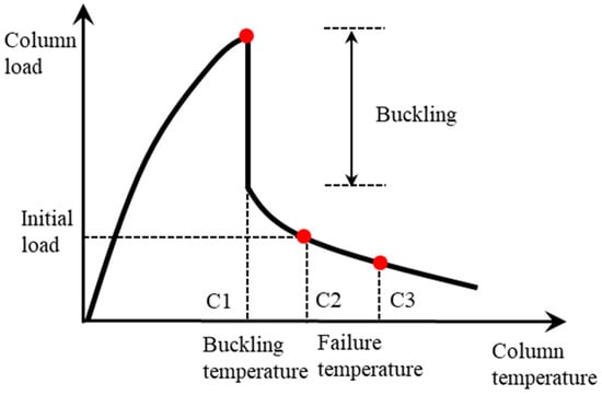
Figure 1.
Complete load–temperature relationship of an axially restrained steel column [12].
It should be pointed out that previous research takes the point when the reaction force in the columns returns to the applied load in the tests as the limit [19,20]. However, the structure stiffness will further constrain the deflection of the column and inhibit further deflection of the column, as shown in the experimental research conducted at Tongji University [16]. Thus, the column deflection limit () or deflection rate () is chosen as its failure criterion here to more realistically describe the performance of the constrained column in the structure. Meanwhile, previous research has mainly focused on the steel column expansion phase during a fire and neglected the contraction phase, leading to disparities in the conclusions regarding the impact of axial restraint stiffness on the fire resistance of steel columns. To clear the doubts around the structural fire design of continuous steel columns, the following research objectives could be achieved through this study:
- Exploring the structural fire performance of restrained continuous steel columns;
- Discussing the fire resistance of continuous columns using the deflection limit or deflection rate as the failure criteria instead of the point of internal force returning back to the initial value;
- Investigating the single-sided lateral moments from the connected steel beam on restrained continuous steel columns;
- Assessing the reliability of current structural fire design procedures considering the restraint effect on steel columns.
2. Development of Finite Element Models
A comprehensive three-dimensional numerical model was formulated to simulate the fire behavior of structural elements using the general-purpose nonlinear finite element analysis software ABAQUS 2017 [21]. In ABAQUS, there are two methods for solving thermal stress problems: uncoupled thermal stress analysis and coupled thermal stress research. A coupled thermal stress analysis is highly recommended for mutually affected structures, as it accounts for the interaction between the thermal and mechanical fields. However, the structural deformation of steel elements in steel-framed systems plays a limited impact on their thermal performance. Therefore, a sequentially coupled thermal stress analysis was performed herein. The sequentially coupled thermal stress analysis has two steps, heat transfer analysis and stress analysis, in which the heat transfer analysis results serve as the temperature load in the following stress analysis (the explicit solver). A time scale was adopted here setting to 1:100, which implies that 3600 s of heating could be replicated in 36 s in ABAQUS [22].
The heat transfer theory deals with the movement of heat energy from hotter areas to cooler areas. This phenomenon can be expressed mathematically using three different methods, conduction, convection, and radiation, in ABAQUS. The ISO-834 standard fire curve was employed to simulate the fire progress in the structure herein. The corresponding convective heat transfer coefficient is 25 , and the emissivity factor is 0.7. The thermal property of the steel, including the specific heat, thermal conductivity, and thermal expansion, is given in EN 1993-1-2 [23]. For the surfaces that were not exposed to fire, there was no application of a thermal boundary condition, which is also referred to as adiabatic. The Stefan–Boltzmann coefficient was 5.67 × 10⁻⁸ W/(m2⋅K4), and the initial temperature of the model was defined as 20 °C. For the stress analysis, the stress–strain relationship of steel at ambient and elevated temperatures is given in EN 1993-1-2 [23]. For the input of structural steel property, the measured stress–strain relationship should be transferred into the true stress–strain relationship to fill the requirement of ABAQUS. The true engineering stresses () and true plastic strains () are presented in Equations (1) and (2).
With a thickness much less than the other two dimensions, shell elements work well in simulating structural components, such as beams, columns, and slabs. A lot of research [8,24] has used shell elements in the simulation, achieving an accurate replication of the experimental results [25]. Thus, the four-noded doubly curved shell element DS4 was employed herein to simulate the heat transfer analysis in the first step. It combines the piecewise quadratic interpolation of the temperature through the thickness of the shell and the linear interpolation on the reference surface of the shell. Mesh size is one of the key parameters determining the accuracy and efficiency of the simulation. All steel columns herein were modeled with a mesh of 20 mm × 20 mm.
The connected structural components restrain the longitudinal deformation of the column, both the expansion and contraction, presenting as the axial stiffness in the simulation, which is assumed as linear herein. ABAQUS provides users with connector elements (CONN3D2) that establish discrete physical connections between deformable and rigid bodies. The connector element is the kinematic constraint allowing the relative motion of the components, providing a connection between two nodes that act along the line connecting the nodes. The axial restraint ratio of the column is taken as the relation between the applied axial stiffness to the column elastic axial stiffness .
The initial geometric imperfection, as prescribed by EN 1993-1-2 [23], is set at L/1000. Utilizing eigenvalue (elastic buckling) finite element analysis, the column’s buckling pattern is established. This outcome serves as the initial imperfection input for the subsequent analysis. The simulation methodology detailed in this section is adopted for the following numerical validation in Section 3.
3. Numerical Validation against Experimental Results
The effectiveness and accuracy of the developed finite element model were tested against the experimental findings of Correia et al. [10]. In the tests, the internal axial force on the top of the column was applied using a hydraulic jack, which was mounted on the reaction frame, as shown Figure 2a. To imitate the constraint, another hydraulic jack was taken here to confine the axial movement of the steel column. All of the tested specimens were pinned to the top and fixed to the bottom, which was accurately repeated in ABAQUS, as shown in Figure 2b. The offset distance of the top reference point to the column is 30 mm, representing the endplate’s thickness. More experimental details can be found in [10].
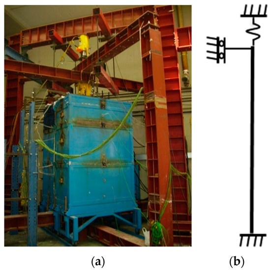
Figure 2.
General view of the test set-up [6] and simplified simulation model. (a) General view of the test set-up; (b) simplified simulation model.
The steel column was coupled to the reference locations via a rigid body connection. There were three degrees of freedom available to the top reference points (UZ = FREE, RX = FREE, RY = FREE). The column bottom is fixed in the established model. The key information has been summarized in Table 1, in which is the load ratio, is the steel yield strength, is the slenderness of the column, and and are the limiting temperatures in the tests and simulations. The average value of the column limiting temperature ratio in the simulation and test ( is 1.04. The minimal difference indicates that the developed model is able to predict the limiting temperature of steel columns. The to the temperature curve between the simulation and testing in Figure 3 shows the developed model can capture the internal force development in steel columns. The next section presents a parametric numerical investigation to assess the impact of the key input parameters. The simulation accurately predicts the failure temperature of restrained steel columns in the experiments for all the tested columns. However, the simulated exhibits a more rapid increase in HEA200-K128-L30 (HEA represents the cross-section dimension; K represents the restraint ratios; L represents the load ratio), which could be that the imperfection in the columns was not fully represented in the simulation. It is worth noting that imperfections tend to be more sensitive in highly restrained steel columns.

Table 1.
Comparison between simulation and experiment results.
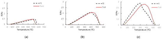
Figure 3.
Comparison of to the temperature of the steel columns. (a) HEA200-K13-L30; (b) HEA200-K45-L30; (c) HEA200-K128-L30.
4. Parametric Studies of Compact Steel Columns
A parametric study was conducted to evaluate their effect on the performance of steel columns in fire. The simulation method used here has already been fully depicted in Section 2. A series of parametric studies comprising 168 models is presented, in which the influence of the axial restraint ratios, column slenderness, column continuity, lateral restraint, axial load ratio (0.3–0.8), and eccentric loading is investigated. The benchmark column cross-section is 310UC 158 for the parametric study. The axial load ratio () ranges from 0.3 to 0.8 of the member capacity in compression () at room temperature. The studied 3 m in length column section is 310UC158 with a yield strength of 300 MPa. Practical axial restraint ratios ( = 0.05–0.35) and rotational restraint ratios (= 0–0.9) on the columns from Faris et al. [26] and Lennon et al. [8] are adopted here.
In multi-story steel-framed structures, steel columns are likely to be heated on a single story and concurrently sustain the effect coming from the un-heated part of the continuous steel columns. The axial constraint creates additional uncertainty in the performance of continuous steel columns in severe fire cases. Thus, continuous steel columns exposed to uneven fire are simulated, as shown in Figure 4. The single-sided lateral restraint effect from the slab and beam is also assessed here through two additional models. The steel column with lateral restraint represents that the lateral movement at the column’s middle height is fixed. The steel column without lateral restraint represents that the column’s middle height is free to move horizontally. The calculation of the limiting temperature followed the design guideline of EN 1993-1-2: 2005 [27].
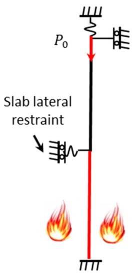
Figure 4.
Simulation of continuous steel columns with un-heated parts in fire. Note: The heating impact from the bottom part of the column to the upper column was neglected.
5. Analysis and Discussion
5.1. Failure Criteria of Restrained Columns
The limiting temperature of the studied columns with different axial restraint ratios is given in Table 2. The effect of the axial restraint ratios on 3 m-long 310UC158 columns is studied, as is the case study in this section. The loading and heating conditions of the steel column with and are shown in Figure 5a. The time–axial deformation curve is given in Figure 5b, which also indicates that the steel column has substantial resistance to fire at C2 (), and using C2 as the limit could significantly underestimate the fire resistance of the steel columns. The deformation shape is shown in Figure 5c. It is clear that the column just reached its plastic deformation and is still far away from its ultimate limit stage, as given in Figure 5d. Thus, the limiting vertical contraction [27], , is taken as the failure criteria herein.
Table 2.
Summary of examined column under various heating conditions, restraints, and load ratios.
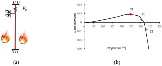
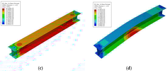
Figure 5.
Simulation results of steel column 3 m in length. (a) Standard test on steel column in fire (L = 3 m); (b) deflection temperature curve; (c) plastic deformation at ; (d) plastic deformation at deflection limit.
5.2. Axial Load and Restraint Ratios
The axial load ratio is a critical parameter for calculating steel columns’ fire resistance limits. This section investigated the unknown influence of the combined axial restraint stiffness and load ratios on the fire resistance of steel columns. The simulation results for 3 m-long columns are shown in Table 2, demonstrating that the limiting temperature of the steel columns constantly declined with an increasing axial load. However, it should be noted that the constraining influence on the compressive deformation of the column decreased with the axial load ratio increment. This is because the restraining effect ( = 0.1–0.35) on the steel columns was minimal in comparison to their load capacity. Once the column started to contract due to axial compression, the restraint stiffness from related structural parts was unable to compensate for the column capacity loss.
A conclusion can be drawn based on the structural fire simulation data in Table 2; the axial restraint does not always reduce the fire resistance of the steel columns here. On the contrary, the fire resistance of the steel columns increases slightly for the 3 m-long steel columns with a load ratio less than or equal to 0.8. This is because the structural stiffness not only suppresses the column expansion but also restrains the column axial contract, inducing a higher limiting temperature.
5.3. Continuity of Steel Columns
The column continuity could play a significant effect on the overall performance of continuous steel columns because parts of the steel column are at high temperatures and other parts are not leading to a non-uniform temperature distribution along the column, as shown in Figure 6. Figure 6 depicts the failure model of the steel columns in the two instances mentioned above, lateral restraint or not. The major difference between the column failure models is the lateral deflection of the steel column at the middle height. As demonstrated in Table 2, the fire resistance of continuous steel columns in the two preceding situations is quite comparable. This is because the compact column in the fire can also achieve the full section yield strength before generating local flange or web bucking. Thus, the yielding of the steel elements resulted in the final failure of the steel columns. Meanwhile, the increasing axial restraint ratios did not change the fire resistance of the continuous steel columns, as well as for the continuous columns.
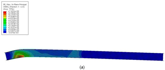
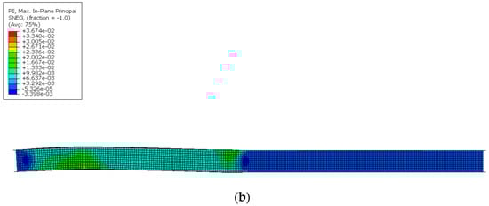
Figure 6.
Column failure model with and without restraint on the column, mid-span. (a) Without lateral restraint on the column, mid-span; (b)with lateral restraint on the column, mid-span.
5.4. Single-Sided Lateral Moment
The loads on the primary beams would generate a bending moment from the connection bolts at the column center (), as shown in Figure 7. The loads from the major axis would cancel each other for the internal columns, making little difference for the axially loaded internal columns. However, the column located at the edge of a structure could sustain the bending moment from the connected steel beam from one side, named the single-sided lateral moment herein. As shown in Figure 7a, in the edge columns, with only one primary beam coming into the column, the loads through the bolts generate an eccentric loading condition. However, in this case, the continuous column would perform differently compared with those ones under axially loaded columns. To fully capture the performance of the edge columns, the bending moment from the connected steel beam of one side was simulated.
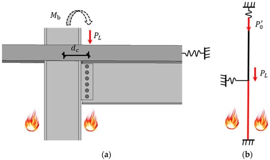
Figure 7.
Schematic drawing of eccentric loading from beam to column. (a) Realistic loading condition; (b) simplified simulation model.
A 6 m 310UC158 continuous steel column numerical model was established in ABAQUS, as shown in Figure 7b, where was half of the value applied on the column top, and = 100 mm was selected here. The suggested value for restraint stiffness of the slab was 1 kN/mm, according to the research of Mago et al. [28]. The applied load values on the column top () and at middle column height () equal half of the initial load () at room temperature. The simulation results are given in Table 3. Compared with the simulation findings of continuous columns in Table 2, the lateral moment from the connected beam reduced the fire resistance of the steel columns to some extent. This is mainly because the eccentric loading increases the lateral deflection of the steel columns induced by the local buckling.
Table 3.
Summary of continuous columns with lateral moment.
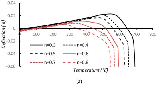
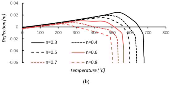
Figure 8 depicts the deflection temperature curve for steel columns with lateral bending moment. When the load ratio was less than 0.5, the temperature limit of the steel columns with eccentric loadings was comparable to that of continuous steel columns without the lateral moment from Table 2. In contrast, when the load ratio was higher than 0.5, the temperature differential between the two sets increased. Because the growing load ratios simultaneously increased the bending moment produced by the , the instability of the steel columns in the critical region was exacerbated. Meanwhile, due to the existence of slabs that restrain the further horizontal deflection of steel columns in fire, continuous steel columns reach the minimum temperature requirement. Consequently, it is plausible to conclude that the present design procedure for edge steel columns considering the lateral bending moment from the steel beam is still reliable.
6. Conclusions
This study develops finite element models through ABAQUS to simulate continuous steel column response under varying loading and restraint conditions. The primary research objective was to investigate the structural performance of continuous steel columns under compression due to thermal expansion and contraction during a fire. Numerical models underwent meticulous validation against experimental tests, exhibiting a remarkable ability to accurately project the correlation between the reaction force and the critical temperature in the experiments. Subsequently, a parametric numerical investigation was conducted to explore the influence of critical parameters on the limiting temperature of the steel column.
- The results from the parametric studies indicated that the column retained a substantial loading capacity when the internal axial force of the columns returned to the applied value ();
- The increasing axial restraint stiffness ratio () did not have a detrimental effect on the fire performance of the steel columns investigated. This was primarily due to the restraint stiffness suppressing the column contraction as well;
- Although the single-sided bending moment from the connected steel beam resulted in an accelerated deflection of the columns in fire, the results demonstrated that steel columns still had sufficient fire resistance when compared to the designed limiting temperature;
- The comparison of the simulation against the design standard showed that the current design approach in EN 1993-1-2: 2005 was conservative in predicting the limiting temperature of internal and edge columns.In light of these findings, it is recommended that prospective investigations be undertaken to formulate an innovative design methodology that systematically incorporates the restraint effects from interconnected elements.
Author Contributions
Conceptualization, J.S. and F.M.; methodology, F.M.; software, J.S. and F.M.; validation, J.S. and F.M.; formal analysis, J.S.; investigation, J.S.; data curation, J.S. and F.M.; writing—original draft preparation, J.S.; writing—review and editing, K.A. and G.C.C.; supervision, F.M.; project administration, F.M. All authors have read and agreed to the published version of the manuscript.
Funding
This research received no external funding.
Institutional Review Board Statement
Not applicable.
Informed Consent Statement
Not applicable.
Data Availability Statement
Not applicable.
Conflicts of Interest
The author declares no conflict of interest.
References
- Kelly, F.; Sha, W. A comparison of the mechanical properties of fire-resistant and S275 structural steels. J. Constr. Steel Res. 1999, 50, 223–233. [Google Scholar] [CrossRef]
- Meng, F.; Zhu, M.-C.; Mou, B.; He, B. Residual strength of steel-reinforced concrete-filled square steel tubular (SRCFST) stub columns after exposure to ISO-834 standard fire. Int. J. Steel Struct. 2019, 19, 850–866. [Google Scholar] [CrossRef]
- Meng, F.-Q.; Zhu, M.-C.; Clifton, G.C.; Ukanwa, K.U.; Lim, J.B. Performance of square steel-reinforced concrete-filled steel tubular columns subject to non-uniform fire. J. Constr. Steel Res. 2020, 166, 105909. [Google Scholar] [CrossRef]
- Meng, F.-Q.; Zhu, M.-C.; Clifton, G.C.; Ukanwa, K.U.; Lim, J.B. Fire performance of edge and interior circular steel-reinforced concrete-filled steel tubular stub columns. Steel Compos. Struct. 2021, 41, 115–122. [Google Scholar]
- Rodrigues, J.C.; Neves, I.C.; Valente, J. Experimental research on the critical temperature of compressed steel elements with restrained thermal elongation. Fire Saf. J. 2000, 35, 77–98. [Google Scholar] [CrossRef]
- Li, G.-Q.; Wang, P.; Wang, Y. Behaviour and design of restrained steel column in fire, Part 1: Fire test. J. Constr. Steel Res. 2010, 66, 1138–1147. [Google Scholar] [CrossRef]
- Wang, P.; Wang, Y.; Li, G.-Q. Behaviour and design of restrained steel column in fire: Part 2. Parameter study. J. Constr. Steel Res. 2010, 66, 1148–1154. [Google Scholar] [CrossRef]
- Pournaghshband, A.; Afshan, S.; Foster, A. Structural fire performance of axially and rotationally restrained stainless steel columns. Thin-Walled Struct. 2019, 137, 561–572. [Google Scholar] [CrossRef]
- Rodrigues, J.P.C.; Laim, L. Fire response of restrained composite columns made with concrete filled hollow sections under different end-support conditions. Eng. Struct. 2017, 141, 83–96. [Google Scholar] [CrossRef]
- Correia, A.J.P.M.; Rodrigues, J.P.C. Fire resistance of steel columns with restrained thermal elongation. Fire Saf. J. 2012, 50, 1–11. [Google Scholar] [CrossRef]
- Correia, A.J.M.; Rodrigues, J.P.C.; Gomes, F.C. A simplified calculation method for fire design of steel columns with restrained thermal elongation. Comput. Struct. 2013, 116, 20–34. [Google Scholar] [CrossRef]
- Wang, Y. Postbuckling behavior of axially restrained and axially loaded steel columns under fire conditions. J. Struct. Eng. 2004, 130, 371–380. [Google Scholar] [CrossRef]
- Wang, W.; Zhang, L.; Ge, Y.; Xu, L. Behaviour of restrained high strength steel columns at elevated temperature. J. Constr. Steel Res. 2018, 148, 251–264. [Google Scholar] [CrossRef]
- Zhang, C.; Gross, J.L.; McAllister, T.P.; Li, G.-Q. Behavior of unrestrained and restrained bare steel columns subjected to localized fire. J. Struct. Eng. 2015, 141, 04014239. [Google Scholar] [CrossRef]
- Yang, J.; Xia, Y.; Wang, W.; Al-azzani, H. Fire resistance of axially restrained Q690 H-shaped welded steel columns: Test, simulation and design. J. Constr. Steel Res. 2021, 177, 106413. [Google Scholar] [CrossRef]
- Jiang, B.; Li, G.-Q.; Li, L.; Izzuddin, B. Experimental studies on progressive collapse resistance of steel moment frames under localized furnace loading. J. Struct. Eng. 2018, 144, 04017190. [Google Scholar] [CrossRef]
- Feng, R.; Huang, Z.; Chen, Z.; Roy, K.; Chen, B.; Lim, J.B. Finite-element analysis and design of stainless-steel CHS-to-SHS hybrid tubular joints under axial compression. Thin-Walled Struct. 2020, 151, 106728. [Google Scholar] [CrossRef]
- Maraveas, C. Local buckling of steel members under fire conditions: A review. Fire Technol. 2019, 55, 51–80. [Google Scholar] [CrossRef]
- Huang, Z.-F.; Tan, K.-H. Structural response of restrained steel columns at elevated temperatures. Part 2: FE simulation with focus on experimental secondary effects. Eng. Struct. 2007, 29, 2036–2047. [Google Scholar] [CrossRef]
- Tan, K.-H.; Toh, W.-S.; Huang, Z.-F.; Phng, G.-H. Structural responses of restrained steel columns at elevated temperatures. Part 1: Experiments. Eng. Struct. 2007, 29, 1641–1652. [Google Scholar] [CrossRef]
- Dassault Systèmes Simulia. ABAQUS Analysis User’s Manual (Version 6.14); Dassault Systèmes Simulia: Providence, RI, USA, 2016. [Google Scholar]
- Mago, N.; Hicks, S.J. Fire behaviour of slender, highly utilized, eccentrically loaded concrete filled tubular columns. J. Constr. Steel Res. 2016, 119, 123–132. [Google Scholar] [CrossRef]
- Cai, J.-M.; Pan, J.-L.; Wu, Y.-F. Performance of steel-reinforced square concrete-filled steel hollow section (SRSCFSHS) columns under uniaxial compression. Adv. Steel Constr. 2016, 12, 410–427. [Google Scholar] [CrossRef]
- Kyvelou, P.; Gardner, L.; Nethercot, D.A. Finite element modelling of composite cold-formed steel flooring systems. Eng. Struct. 2018, 158, 28–42. [Google Scholar] [CrossRef]
- Meng, F.; Mago, N.; Andisheh, K.; Clifton, G.C. Numerical validation of structural fire design for steel framed car park buildings. Fire Saf. J. 2023, 139, 103819. [Google Scholar] [CrossRef]
- Ali, F.; O’Connor, D. Structural performance of rotationally restrained steel columns in fire. Fire Saf. J. 2001, 36, 679–691. [Google Scholar] [CrossRef]
- EN 1993-1-2; Eurocode 3: Design of Steel Structures-Part 1-2: General Rules-Structural Fire Design. European Committee for Standardization: Brueeels, Belgium, 2005.
- Mago, N. Influence of Slab Panel Edge Sagging in Fire–Stage 2 of the SPM: Concise Summary; Rep. No. R4-118.1; New Zealand Heavy Engineering Research Association: Manukau City, Auckland, 2004. [Google Scholar]


Disclaimer/Publisher’s Note: The statements, opinions and data contained in all publications are solely those of the individual author(s) and contributor(s) and not of MDPI and/or the editor(s). MDPI and/or the editor(s) disclaim responsibility for any injury to people or property resulting from any ideas, methods, instructions or products referred to in the content. |
© 2023 by the authors. Licensee MDPI, Basel, Switzerland. This article is an open access article distributed under the terms and conditions of the Creative Commons Attribution (CC BY) license (https://creativecommons.org/licenses/by/4.0/).