1. Introduction
As is known to all, indoor public amenities, as a new entertainment venue, can meet the growing demands of recreation and leisure. However, due to the growing density of visitors, in some cases, visitors’ activities are restrained, and related fire safety issues are prominent. A case in point is the potential fire risk of large-scale entertainment parks with indoor track riding projects. It is different from the public entertainment places which have been defined by the code for fire-protection design of buildings [
1] because the public amenities in the code mainly refer to the unrestricted entertainment activities of visitors, such as electronic entertainment halls, bowling venues and other entertainment projects, while in indoor riding activities tourists need to be fixed on the seats and move along the track.
Performance-based fire-protection design (PBFD), usually used as an engineering compensation to the code requirements, has been widely adopted since some fire scenarios are not included or considered in the current codes or regulations [
2,
3,
4,
5]. It was first brought forward in the 1970s. After years of development, mandatory codes have gradually adopted the PBFD for the prescriptive code design [
6,
7]. It brings flexibility to the code-based fire-protection design by introducing acceptable methods, criteria, and performance objectives. Meanwhile, it ensures that the designed environment could meet the specified demands of fire, life safety, property protection, business continuity, and environmental protection.
PBFD has been studied by many researchers from home and abroad and used in many situations. Zhao and Shen [
8] have developed a numerical model by using finite element software ABAQUS to predict the fire resistance of the planer steel tube truss structures. Li et al. [
9,
10] have developed a finite element model by using ABAQUS for analyzing the nonlinear fire performance of steel frames. Yin and Wang [
11,
12] have done a series of studies on the fire resistance of steel beams. Thomas and Negar [
13] proposed recommendations for PBFD of composite steel buildings. Ma et al. [
14] extended the PBFD to the bridge structures under vehicle-induced fire accidents.
However, previous research about public amenities with restrained personnel activities is still small in number. Zheng [
15] and Zhang [
16] proposed some fire safety measures and demonstrated the PBFD of a large indoor theme park in response to the difficulties based on existing standards. A fire protection design plan was proposed from the aspects of fire protection general layout, combustible control, fire separation measures, evacuation and smoke exhaust design. Zhao [
17] introduced the PBFD of a large indoor amusement park project, as well as the basic preparation work and the construction scheme.
However, again, the characteristics of restrained personnel activities were not considered and discussed at all. Thus, the main focus of this paper is to explain the PBFD in indoor public amenity with restrained personnel activities.
In this paper, for large-scale entertainment parks with restrained personnel activities such as indoor track riding projects, the traditional performance-based fire-protection design method is still used while several new aspects or considerations that are not covered by the current code are brought forward, and corresponding solutions are proposed. Those new aspects are shown just as follows.
- (1)
No code for determining the personnel density and evacuation plans in places such as serpentine queue area.
- (2)
Tourists in the recreation area travel through several different scenes by boat. During the tour, tourists need to be fixed on the tour vehicles for safety reasons. And the entertainment area is also equipped with large scenery, all of which are inaccessible to personnel. Therefore, how to effectively organize personnel evacuation and avoid panic in the fire is another difficulty and focus of the entire fire protection design of this paper.
- (3)
Design of fire detection and alarm system in the entertainment area.
- (4)
Design of smoke control in entertainment areas.
- (5)
Design of fire extinguishing systems in entertainment areas.
On the other hand, in order to solve the emerging new problems of PBFD when used in different fire scenarios, a few new numerical simulation tools, such as the computational fluid dynamics (CFD) and according simplified models, have been developed. It has been already included in the practical design instructions, codes and regulations [
18,
19,
20,
21,
22,
23,
24]. According to the performance objectives, the above tools could still be adopted in this paper’s case as long as the equivalent level of fire safety could be achieved, such as available safe evacuation time (ASET) and required safe evacuation time (RSET) methods. And the effectiveness of the fire-protection and evacuation strategy in the fire was proposed to be justified from the life safety perspective.
Above all, the whole paper is focusing on the PBFD for the public amenities with restrained personnel activities by conducting smoke control and evacuation simulations. Fire safety measures for this kind of fire scenario are proposed, discussed and verified.
2. Performance Objectives and Fire-Protection Strategies
Park A is a typical public amenity with an indoor track riding facility, in which track riders’ activities are restrained. The facility has one floor above the ground mainly, and locally, there are two floors. It is a steel frame structure, with a height of 21 m and a total area of 11,000 m2. The fire resistance rating of the building is grade II. By referring to the similar public amenities provided by the design code and according to the design requirements, fire-protection performance objectives mainly include the following:
Meet the life safety of personnel (primary objective) and ensure that the personnel in the affected area can be evacuated to the safe area or outdoors.
Prevent the spread of smoke and fire, reduce property losses and protect the environment.
In order to achieve above performance objectives, major fire-protection strategies for public amenities with restrained personnel activities are introduced as follows.
- (1)
Although the building has been provided with a comprehensive automatic extinguisher system, the fire-resistance limits of all structural members are still designed as structures without a comprehensive automatic extinguisher system according to the code for fire safety of steel structures in buildings [
25], as listed in
Table 1, taking the characteristic of restrained personnel activities into consideration.
- (2)
This building is equipped with a circular fire lane, as shown in
Figure 1, with a clear width and height of ≥4 m. The distance between the fire lane and the exterior wall of the building is larger than 5 m, and the minimum radius of the fire lane is also bigger than 12 m. Therefore, it meets the demands of fire-fighting trucks. The fire lane and its underlying building structures, pipelines and trenches can withstand the pressure imposed by heavy fire-fighting trucks.
- (3)
This project is a tourist building in which tourists can ride the cockpit along the track, and the cockpit can rotate from multiple angles. The building includes waiting areas, riding areas, inspection areas, equipment areas and shops, with a total construction area of 10,431 m
2. The building is designed to be divided into two fire compartments, as shown in
Figure 2.
- (4)
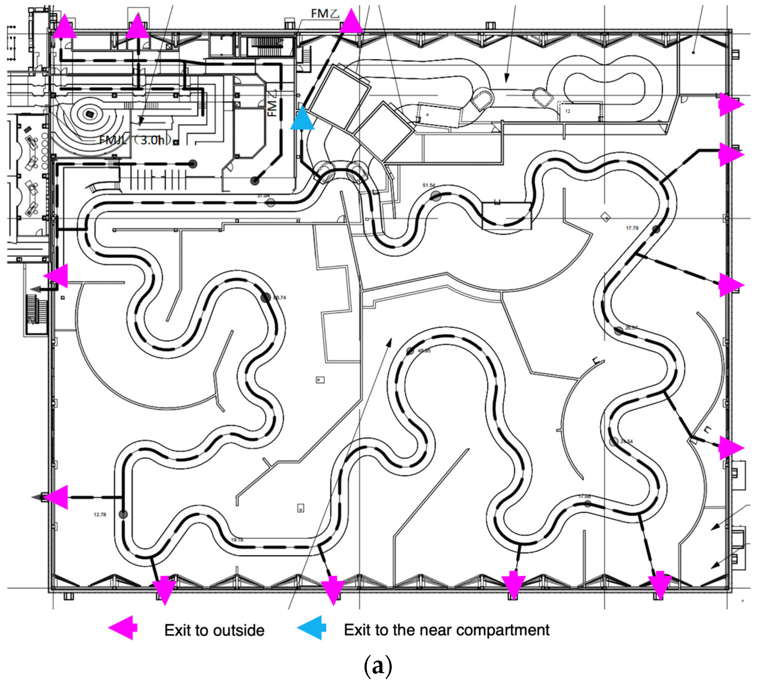
The whole riding area is equipped with 13 emergency exits directly to the outside. The number and space between emergency exits meet the demands of codes, as shown in
Figure 3.
- (5)
The specific evacuation strategies for people in the riding area and travel in the cockpit along the track are provided as below.
In the riding area, a total of 16 vehicles are running along the track, and 2 vehicles are used as backup in the offline inspection room. Each vehicle can carry 12 people, with 3 rows of seats and 4 people in each row. Therefore, during peak time, the maximum number of tourists in the vehicles is 192. Two kinds of emergency evacuation strategies or procedures are brought forward based on the realistic situation, namely Cycle Out Procedure and Emergency Stop Procedure.
Cycle Out Procedure means that when the fire does not affect the safety of personnel in the vehicles, the vehicles in the riding area can continue to ride under the monitoring of the riding-control room until the vehicle reaches the destination. Then, tourists can leave the vehicles and evacuate according to the instruction of staffs.
Cycle Out Procedure may no longer be suitable under certain circumstances, such as electricity blackout or riding facility failure and so on. Then, it is necessary to start the Emergency Stop Procedure, in which tourists have to evacuate from the place where the vehicle stops, as shown in
Figure 4.
- (6)
Because the height of the dark-riding building has exceeded 12 m, according to the current code GB50116 [
26], traditional fire detectors will no longer be suitable. The standard also recommends setting up two types of fire detectors at the same time. Fire detector products mainly include pipeline-suction-type detectors, infrared-beam-type smoke detectors, image-type smoke detectors, point-type infrared flame detectors, image-type flame detectors and so on. By comparing various types of detectors, considering that materials of this project are mostly flame retardant, and the obstacles such as scenery and props in the space are obstructed, pipeline-sucking-type detectors are mainly used, as shown in
Figure 5, while supplemented by infrared-beam-type smoke detectors.
- (7)
In order to reasonably determine the smoke exhaust volume, it is designed according to “fire scale and clear height method” and “ventilation frequency method”, respectively. And then, the larger value will be taken as the design value.
After calculation, as shown in
Table 2, the design smoke exhaust volume of the riding area and the passenger boarding and alighting area are obtained. The design smoke exhaust volume of riding area shall not be less than 621,000 m
3/h. And the design smoke exhaust volume of the boarding and alighting area shall not be less than 53,760 m
3/h.
- (8)
According to the code of automatic sprinkler fire extinguishing system [
27], automatic sprinkler fire extinguishing system was adopted in the dark riding area. Details were recommended by the code to be the same with grand spaces such as theaters, music halls, convention and exhibition centers and so on. And the boarding area was recommended to use the quick-response sprinkler head.
3. Evaluation Criterion
For such public amenities, the fire safety level of the building should not be simply evaluated from the perspective of distance or area specified in the current fire-protection code. It should be evaluated by comparing the time required for the personnel in the building to safely evacuate with the time required for the fire to reach the human limit.
Therefore, the concept of quantitative "timeline" of personnel safety evacuation in public amenities with restrained personnel activities is proposed in this paper, as shown in
Figure 6.
It includes two key times.
- 1.
The time when a fire spreads beyond the human endurance limit, known as the available safe evacuation time (denoted as ASET)
- 2.
The time for personnel to complete evacuation, known as the required safe evacuation time (denoted as RSET).
Then, the primary objective is achieved when ASET > RSET.
3.1. Available Safe Escape Time—ASET
The ASET is mainly determined by three indicators including visibility and toxicity, thermal effect and clear height. If any of these parameters cannot meet the demands, it is proved that the designed environment would cause casualties. And if the analysis results show that the environment has reached the critical condition before the completion of evacuation, then the fire control strategy needs to be adjusted in order to 100 percent ensure the visitors can reach the emergency exit before the intolerable environmental conditions occur.
3.1.1. Toxicity and Visibility
Toxicity and smoke concentration have a significant impact on the safety of personnel in the fire. The generation and distribution of toxic gas are complex, as well as its impact on human body, so it is difficult to accurately define quantitatively in the fire-protection analysis. For large space or well-ventilated environment, an effective simplified method is usually used in engineering application by measuring the harmful concentration of combustion products to the human body. Considering that the building has large space, the visible distance should be less than 15 m.
3.1.2. Thermal Effect
The thermal effect mainly includes the high temperature of the smoke that the human body can tolerate within a certain time, the radiation of the smoke and the convection of the high temperature from the air to human body, which are determined by the radiant heat density of the smoke and the temperature parameters of the air.
The flashover phenomenon shows that the heat of fire on the human body mainly comes from the thermal radiation of smoke, so the temperature of smoke has a great impact on personnel evacuation. The research shows that the human body can tolerate for several minutes under the thermal radiation intensity of less than 2.5 kW/m
2 [
22]. Through calculation, the heat radiation of 200 °C smoke is about 2.5 kW/m
2. Therefore, the radiation intensity can be equivalent to the smoke with a temperature of 200 °C.
In the fire, it is necessary to ensure that persons are in the air with a clear height below the smoke, as shown in
Figure 5. The temperature of the air has a certain impact on the human body. Experiments have shown that breathing overheated air will lead to thermal shock and respiratory burns, because the absolute humidity of the air in the fire will be much higher than the environment. The harm of saturated air to the human body is much greater than that of dry air. The research shows that 60 °C can be considered as the maximum temperature of inhalable air in the fire.
3.1.3. Clear Height
In addition, when fire happens, the smoke would spread along the ceiling. In the process of spreading, the smoke would go down. When the smoke goes down to the height of persons, the oxygen will inevitably decrease and lead to suffocation.
Therefore, in addition to ensuring the visibility and thermal effect of toxic gases in the space, it is also necessary to maintain the smoke at a certain height. Generally, it is necessary to maintain the smoke above the average height of human body. For the queuing areas, the clear height is 2.2 m. And for the track and entertainment areas, the clear height is 2.3 m and 3.4 m, respectively.
3.1.4. Criterion of ASET
Above all, the fire site with a large space and good ventilation is considered to be tolerable by the human body if the following conditions are satisfied:
- 1.
The visibility distance should be less than 15 m.
- 2.
The radiation intensity of smoke shall not exceed 2.5 kW/m2, and the temperature of air shall not exceed 60 °C.
- 3.
For the queuing areas, the clear height is 2.2 m. And for the track and entertainment areas, the clear height is 2.3 m and 3.4 m, respectively.
3.2. Required Safe Escape Time—RSET
3.2.1. Detection Time Δtdet
The time from fire occurrence to detection is called detection time Δ
tdet. Due to the characteristic of dark riding, the internal light is insufficient, and the setting in the scene is complex. Therefore, it will be more difficult to detect the fire. Through simulation, the fire detection time of the riding area is about 75 s, as shown in
Figure 7.
3.2.2. Alarm Time Δta
The time from fire detection to notifying the personnel is the alarm time Δta. Based on the emergency response operation process and crisis handling capacity of the global operation team, it will be confirmed within 1 minute through manual and closed-circuit monitoring system. Therefore, the time for staff to confirm the fire and alarm is 60 s.
3.2.3. Pre-Movement Time Δtpre
The pre-movement time of personnel evacuation is the time interval between the personnel receiving the fire alarm and the start of evacuation, including recognition time and response time. By referring to the relevant descriptions of British standard and the guidelines for performance-based fire-protection design [
22], typical recognition and response time of various types of alarm systems are shown in
Table 3.
3.2.4. Travel Time Δttrav
The travel time is mainly from the time when people begin to evacuate to the time when people get out of the emergency exit. The travel time is closely related to the time of personnel and building characteristics.
3.2.5. Criterion of RSET
Above all, the RSET can be calculated by the following equation, as shown in Equation (1).
4. Fire Scale and Scenes Design
The determination of the fire scenes and scales are the first step of performance-based fire-protection design and the basis of numerical simulation. After the fire scale is determined, the smoke exhaust rate or the response of the structure in the fire can be calculated by simulation. Therefore, the fire scene and scale design is of great significance for the performance-based fire-protection design.
4.1. Determination of Fire Scale
The fire scale is proposed to be determined according to the requirements of corresponding codes just as follows.
- 1.
According to the Material Flammability judgment index required by the specification GB/T 16172 [
28], the peak heat release rate of audio/video/electrical product shell with combustion performance of B1 is 150 kW/m
2.
- 2.
According to the index of combustibility of materials required by specifications GB/T 16172 [
29], the heat release rate data of flame-retardant foam plastics are considered conservatively according to the most unfavorable situation in grade B1, and the peak value of heat release rate is about 250 kW/m
2.
- 3.
According to the heat release rate data of FRP constituent materials given by ASTM E 1354 [
29], the peak heat release rate of FRP is about 294 kW/m
2, and 90% is below 200 kW/m
2.
- 4.
According to the plywood heat release rate data provided in the references [
30], the peak heat release rate of flame retardant plywood shall not exceed 150 kW/m
2.
All in all, by considering that there may be flexibility in the layout of scenery, in the later stage of the riding area, from a relatively conservative point of view, the peak value of indoor heat release rate per unit area is designed to be 250 kW/m2. And it is conservatively considered that the average burned area without spraying is 24 m2. Then, it can be calculated that the fire scale in the riding area is 250 × 24 = 6.0 MW. And for the queuing areas, by considering that the most important possibility in this area is that vehicles may catch fire, the fire scale of this area is conservatively designed as 2.5 MW, according to the fire scale of a small car with reference to the specifications.
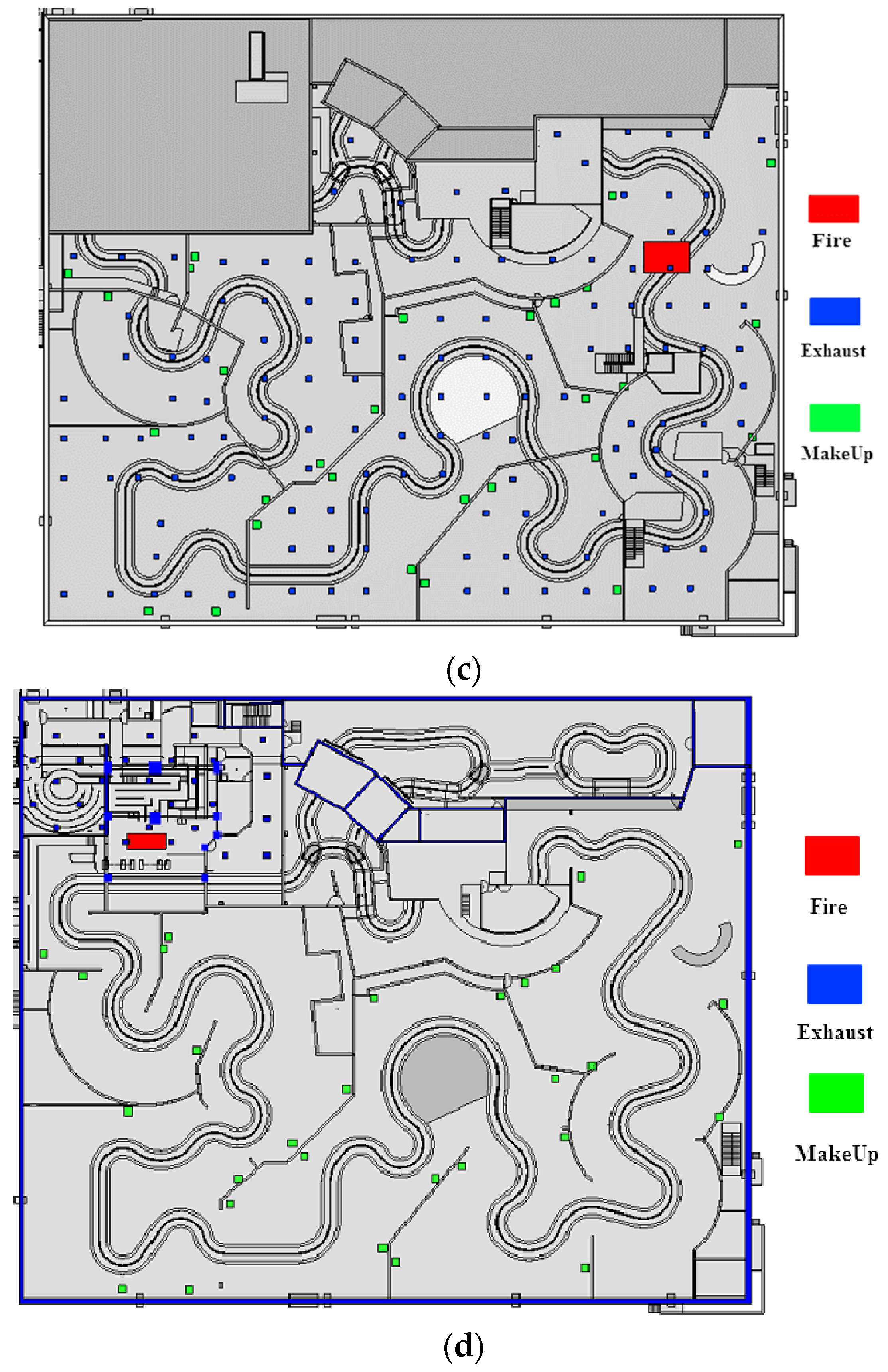
4.2. Design of Fire Scenes
Based on the landscape layout, the locations of fire are those places where the flame-retardant foam cartoon characters are put. Therefore, the location selections of the final design fire scenes are shown in the
Figure 8. And the scene setting and distribution of simulation analysis using FDS are listed in
Table 4.
5. Smoking Simulation
A reasonable smoke control system can effectively exhaust the smoke out of the building, maintain visibility and lower smoke temperature and toxic gas concentration in the fire environment, so as to create a better environment for personnel evacuation.
In this section, software FDS is used to simulate and design the safety time that the fire environment can provide for the personnel evacuation. LES (Large-eddy simulation) was applied as default.
The Navier–Stokes equations are the basic governing equations for a viscous, heat conducting fluid, which is the basis of CFD. It is a vector equation obtained by applying Newton’s Law of Motion to a fluid element and is also called the momentum equation (Equation (2)). It is supplemented by the mass conservation equation (Equation (3)), also called continuity equation, and the energy equation (Equation (4)).
in which
ρ is the density;
u stands for the molecular viscosity which is a function of temperature;
h stands for the total energy per unit mass.
5.1. FDS Modelling
The FDS models for all fire scenes are shown in
Figure 9, in which the fire heat release rate curves are shown in
Figure 10, and other input parameters are listed in
Table 5.
5.2. Simulation Results
- (1)
Smoke particle spread
The movement of smoke particles output by FDS shows that when a 6.0 MW fire occurs in the riding area of 1#~3# fire scenes and 2.5 MW in the boarding and alighting area of 4# fire scene, the smoke quickly spreads to the whole headspace. The mechanical smoke exhaust is arranged under the berm, which effectively exhausts the smoke, controls the spread of smoke and prevents the smoke from going down. During the simulation, the height of the smoke is always controlled above the clear height. The whole process of smoke spread in 1# and 4# fire scene is shown in
Figure 11.
- (2)
The temperature of fire resource center
The following group of pictures is the vertical temperature slice along the fire source center of the fire scene during the simulation time, and the maximum display temperature is 60 °C, as shown in
Figure 12. The temperature slice at the center of the fire source shows that the smoke temperature at the top is high, and other areas are not greatly affected.
- (3)
Visibility of fire resource center
The smoke spreading process shown by the smoke visibility simulation results is consistent with the trend shown by the temperature results, and the influence range of smoke visibility of 1# and 4# fire scene are shown in
Figure 13.
- (4)
Temperature/visibility of water level 3.4 m above the ground
The visibility and temperature distribution map above the sightseeing area and 3.4 m above the ground at 1800 s, are shown in
Figure 14.
It can be seen that the temperature in the scene area where the fire is located begins to rise, and other scenes maintain room temperature except near the fire. In the horizontal intersection of clear height in the location of fire, only the visibility near the fire declines, and visibility of other areas is still kept more than 15 m. Therefore, it can be concluded that ASET ≥ 1800 s in this fire scenario. The analysis of 2# and 3# fire scenes shows the same conclusion.
The smoke visibility simulation results of 4# fire scene show that the ASET in the boarding and alighting area is more than 1200 s.
5.3. Empirical Calculation
In this paper, an empirical model was also briefly introduced and compared with the FDS results. G.Q. Li et al. [
31] assumed that the field distribution of temperature on the horizontal plane at a known height is polar symmetrical with respect to the fire source center. Then, the temperature field in large space building fires could be simplified as a mathematical model. Based on a large number of numerical simulation results using FDS, empirical formulas were obtained, as shown in Equation (5).
in which
T(
x,
z,
t) is the temperature (°C) of a point in the large-space building with a horizontal projection distance of
x (m) and a vertical projection distance of
z (m) from the fire source at time
t.
T0 is the room temperature before the fire (°C), which can be taken as
T0 = 24 °C.
Tmax is the room temperature (°C) at a distance of
z (m) from the fire source centerline. It can be calculated using the following fitting equation based on FDS results.
in which
Q is the power of the fire source (MW),
A is the area of large space (m
2).
f(
t) is the growth function, which can be calculated using the following equation.
In the equation,
β is the shape coefficient, taken as 0.001, 0.002, 0.003 and 0.004 for slow, medium, fast and extremely fast fires, respectively.
t is the time (s);
ksm is the distance decay coefficient, which is determined by the following formula.
Among them,
η Is the attenuation coefficient, recommended as
Table 6.
D is the diameter of the fire source (m), calculated based on the principle of equal area
Af.
However, it was recommended that
Tmax as calculated by Equation (6) could be obtained by NFPA model, as shown in Equations (10) and (11), since Equation (6) would overestimate
Tmax [
32].
Therefore, according to above empirical equations, in 1#~3# fire scenarios, the temperature is 86 °C at a height of 3.4 m above the ground of the riding area when t equals to 1800 s. And in 4# fire scenario, the temperature is 103 °C at 2.3 m above the ground of the riding area when t equals to 1200 s. Both values are a bit larger than the results of FDS analysis.
5.4. Summary
In the 1#~3# fire scenes, 6.0 MW fire occurs in the riding area, and the existing smoke exhaust volume is used for smoke exhaust in the event of extinguisher system failure. The temperature and visibility at 3.4 m above the ground of the riding area do not reach the critical value during the simulation process, so at least 1800 s evacuation time can be provided. In 4# fire scene, the existing smoke exhaust volume is used for smoke exhaust. The temperature and visibility at 2.3 m above the ground in the passenger loading and unloading track area do not reach the critical value during the simulation process, and the boarding and alighting area can provide an evacuation time of at least 1200 s.
According to the comparison between empirical results and FDS results, it was recommended to conduct FDS analysis in practical projects, since empirical models would overestimate the temperature field.
The FDS analysis results are listed in
Table 7.
6. Evacuation Simulation
In this section, Pathfinder software is used to simulate the overall evacuation of passengers in boarding and alighting areas and indoor riding areas. On the basis of the analysis results, the rationality of evacuation exit setting in relevant areas and the safety of personnel evacuation are evaluated.
6.1. Pathfinder Model
- (1)
Composition and proportion of evacuees
In the analysis of evacuation, the personnel groups in the building are simplified into four types: adult male, adult female, children and the elderly. The proportion of each personnel type is designed based on the actual users of specific functional rooms in the building.
The most unfavorable proportion of personnel will be used for evacuation simulation analysis in this paper. The personnel types and proportions are shown in the
Table 8.
- (2)
Body size of evacuees
The body shape size of personnel varies from country to country. The following body shape data are used in this simulation, as shown in
Table 9.
- (3)
Walking speed of evacuees
There is a certain correlation between the evacuation speed and agility of personnel of different genders in emergencies. In the simulation analysis of personnel evacuation, walking speed values are shown in the
Table 10.
The above speed setting is the average moving speed of different types of personnel in emergency according to a large number of research results and investigation results, which is a kind of horizontal moving speed without obstacles and blockage. The movement speed in the case of obstacles will be automatically adjusted by the simulation software.
- (4)
- (5)
Evacuation exit setting
The distribution of exits in each area is shown in
Figure 3.
- (6)
6.2. Simulation Results
The overall evacuation simulation process is shown in
Figure 16 below.
6.3. Summary
The summary of the evacuation time in each area is shown in
Table 12.
7. Concluding Remarks
In this article, software FDS was used to simulate and design the safety time that the fire environment can provide for the personnel evacuation. According to the FDS simulation, the height of the smoke was always controlled above the clear height, and the temperature in the fire area rose when other places could maintain the room temperature. In addition, the visibility near the fire declined, but the visibility of other areas could be still kept more than 15 m. Therefore, according to above analysis results, ASET could be finally concluded.
Meanwhile, Pathfinder was used to simulate the overall evacuation of passengers in boarding and alighting areas and indoor riding areas. On the basis of the analysis results, the rationality of evacuation exit setting in relevant areas and the safety of personnel evacuation is evaluated. The analysis results showed that the evacuation time was able to be obtained when a safety coefficient equals to 1.5 was also considered.
Table 13 has summarized that the currently fire-protection strategies can achieve the performance objectives [
33,
34].
Above all, the simulation analysis has shown that based on the current performance-based fire-protection design, the fire and smoke spread in the riding area can be effectively controlled, and safe evacuation environment can be provided for the evacuation of tourists. Therefore, the overall fire safety design method and fire-protection strategies brought forward in this article could offer a good reference to the similar public amenities.


