
Modern Kiln Burner Technology in the Current Energy Climate: Pushing the Limits of Alternative Fuel Substitution


Abstract
:1. Introduction
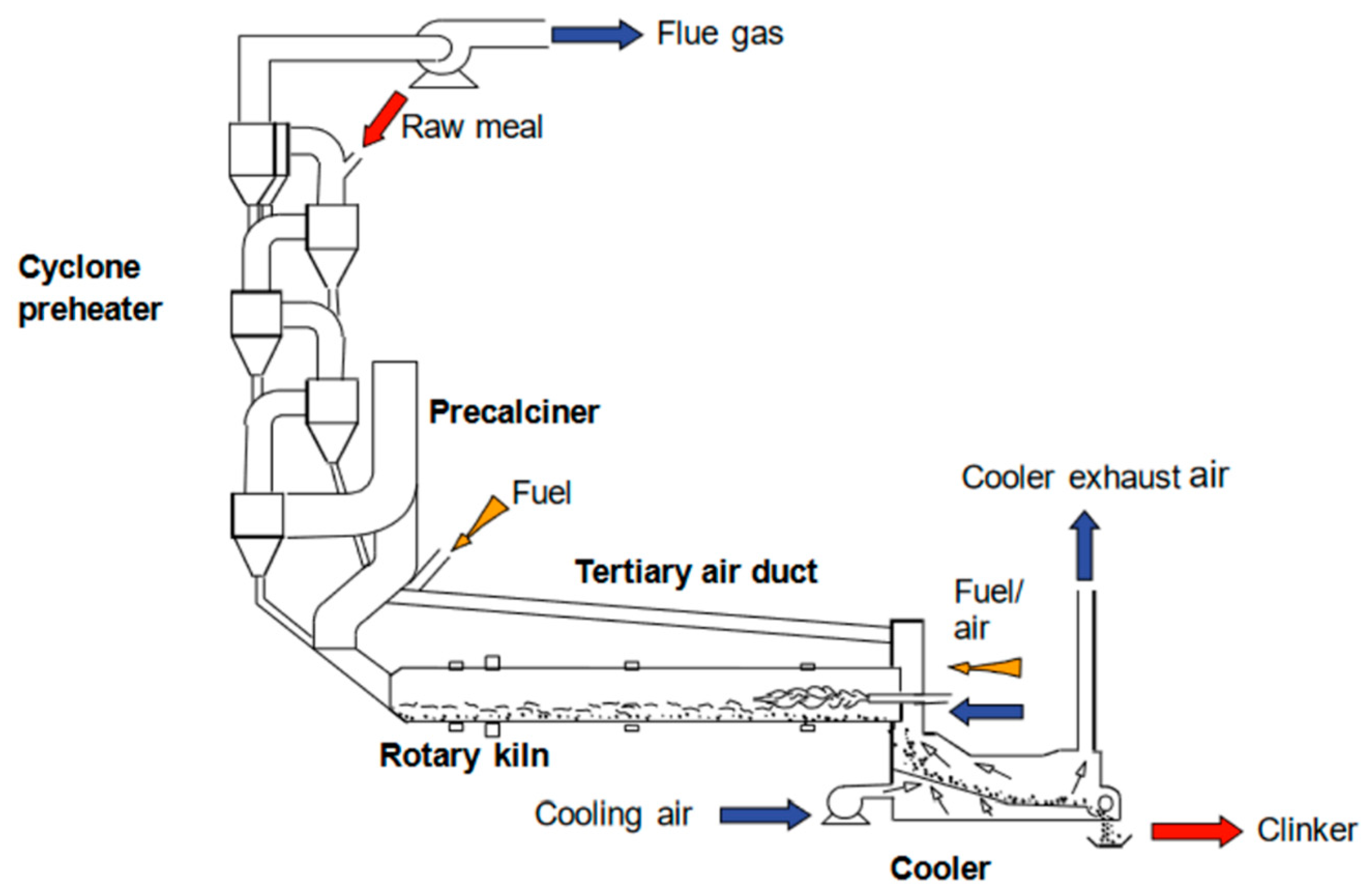
2. The Pyrosystem
3. Fuels
3.1. Coal
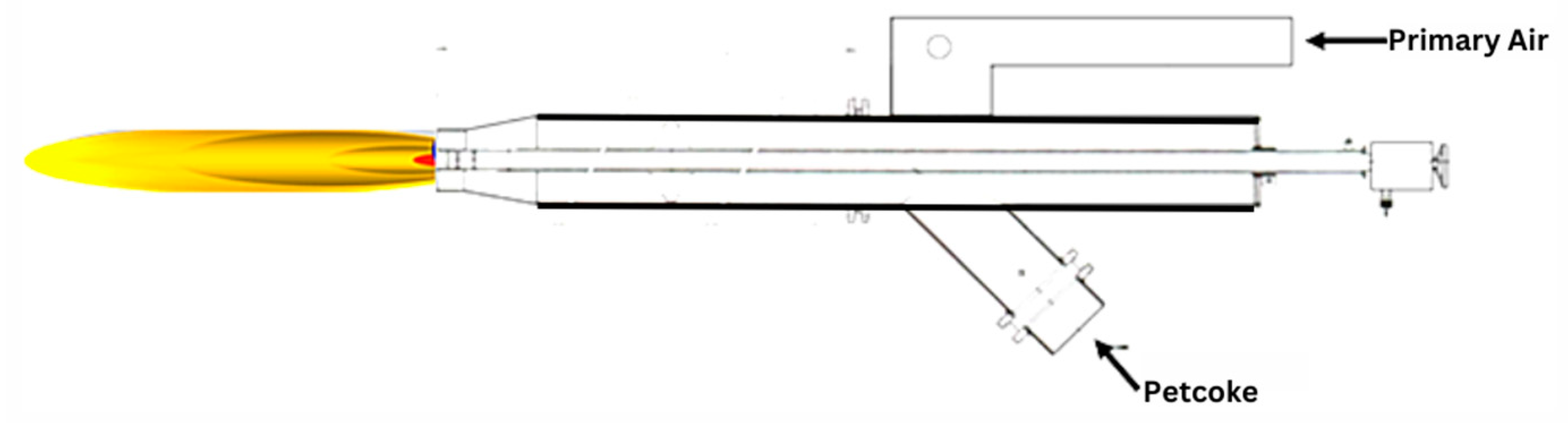
3.2. Petroleum Coke (Petcoke)
3.3. Waste Fuel
- Refuse Derived Fuels (RDF);
- Landfill Gas;
- Tyre Derived Fuels (TDF);
- Meat and Bone Meal;
- Biomass Sludges;
- Waste Liquids.
3.4. RDF Operational Challenges
4. Evolution of Kiln Burners
4.1. First Generation
4.2. Second Generation
4.3. NOx Reductions
- reducing overall combustion temperature;
- avoiding short duration temperature peaks in the process;
- avoiding local temperature peaks in the flame;
- reducing oxygen concentration;
- reducing retention time of fuel in high oxygen environments.
4.4. Third Generation
4.5. FLSmidth
- Burner capacity: 20–250 MW;
- Solid, liquid and gaseous fuel support;
- Primary air pressure: 250–400 mbar;
- Primary air consumption: maximum 15% (standard 6–8%);
- Axial/radial air ratio adjustable (standard 1:2);
- Primary air momentum: 1250–1780% Primary air velocity.
- Maximum burner capacity: 250 MW;
- Flame momentum: 7 N/MW to 11 N/MW;
- Solid and liquid fuel support.
- Fives Pillard.
- Burner capacity: 5–180 MW;
- Primary air fraction: 6–10%;
- Primary air pressure: 150–250 mbar;
- Solid, liquid and gaseous fuels support;
- KHD
- ThyssenKrupp
- Greco
- ○
- Burner capacity: up to 175 MW;
- ○
- Primary air percentage: 10–13% of primary air;
- ○
- Primary air pressure: 50–350 mbar;
- ○
- Burner momentum: 6–7.7 N/MW.
- FCT
- ○
- Burner capacity: up to 160 MW;
- ○
- Solid, liquid and gaseous fuel support;
- ○
- Primary air percentage: approximately 11% (based on a case study);
- ○
- Can achieve alternative fuel substitution rates of 70% (based on a case study).
- Dynamis
- ○
- Primary air percentage: 11.3%;
- ○
- Primary air pressure: 120–430 mbar;
- ○
- Burner momentum: 8.1 N/MW.
5. Discussion
6. Conclusions
Author Contributions
Funding
Conflicts of Interest
References
- Devi, K.S.; Lakshmi, V.V.; Alakanandana, A. Impacts of Cement Industry on Environment—An Overview. Asia Pac. J. Res. 2018, 1, 156–161. [Google Scholar]
- Shrivastava, S.; Shrivastava, R.L. A systematic literature review on green manufacturing concepts in cement industries. Int. J. Qual. Reliab. Manag. 2017, 34, 68–90. [Google Scholar] [CrossRef]
- CEMBUREAU. Activity Report; Brussels, Belgium. 2021. Available online: https://cembureau.eu/media/03cgodyp/2021-activity-report.pdf (accessed on 5 February 2023).
- GNR 2.0—GCCA in Numbers. GCCA. 2022. Available online: https://gccassociation.org/sustainability-innovation/gnr-gcca-in-numbers/ (accessed on 5 January 2023).
- Kiln Burners—Metso Outotec. n.d. Available online: https://www.mogroup.com/products-and-services/plants-and-capital-equipment/kilns/kiln-burners/ (accessed on 28 September 2021).
- Manias, C.G. Kiln Burning Systems. In Innovations in Portland Cement Manufacturing, 2nd ed.; Portland Cement Association: Skokie, IL, USA, 2011; pp. 239–268. [Google Scholar]
- Alsop, P.A. The Cement Plant Operations Handbook: For Dry-Process Plants, 7th ed.; Tradeship Publications: Dorking, UK, 2019. [Google Scholar]
- The Air Circuit in a Rotary Kiln—Infinity for Cement Equipment n.d. Available online: https://www.cementequipment.org/home/kiln-and-cooler/air-circuit-rotary-kiln/ (accessed on 28 September 2021).
- Wirthwein, C.R.; Emberger, B. Burners for alternative fuels utilization—Optimisation of kiln firing systems for advanced alternative fuel co-firing. Cem. Int. 2010, 8, 42–46. [Google Scholar]
- Pedersen, M.N. Co-Firing of Alternative Fuels in Cement Kiln Burners. Ph.D. Thesis, Technical University of Denmark, Lyngby, Denmark, 2018. [Google Scholar]
- Nobis, R.H. Latest rotary kiln burner technology: Possibilities and experiences. IEEE Trans. Ind. Appl. 1991, 27, 798–806. [Google Scholar] [CrossRef]
- Kopp, O.C. Coal; Encyclopedia Britannica Inc.: Chicago, IL, USA, 2020. [Google Scholar]
- Coal for Cement: Present and Future Trends; Global Cement: Epsom, UK, 2016.
- Tian, W.; Yan, F.; Liang, R. Simulation analysis of steam gasification of petroleum coke with CaO. Pet. Sci. Technol. 2018, 36, 2170–2183. [Google Scholar] [CrossRef]
- ASTM D396-21; Standard Specification for Fuel Oils. ASTM International: West Conshohocken, PA, USA, 2021.
- Aranda Usón, A.; López-Sabirón, A.M.; Ferreira, G.; Llera Sastresa, E. Uses of alternative fuels and raw materials in the cement industry as sustainable waste management options. Renew. Sustain. Energy Rev. 2013, 23, 242–260. [Google Scholar] [CrossRef]
- Alternative Fuels in Cement Manufacture; Brussels, Belgium. 2009. Available online: https://www.intechopen.com/chapters/17593 (accessed on 5 February 2023).
- Nørskov, L.K. Combustion of Solid Alternative Fuels in the Cement Kiln Burner. Ph.D. Thesis, Technical University of Denmark, Lyngby, Denmark, 2012. [Google Scholar]
- FLSmidth, “The Next Generation Duoflex Burner Is Here,” Highlights FLSmidth, Nov. 2008. Available online: https://www.flsmidth.com/ (accessed on 5 February 2023).
- DUOFLEXTM Burner. FLSmidth 2019. Available online: https://flsmidth-prod-cdn.azureedge.net/-/media/brochures/brochures-products/pyro/2000-2017/duoflex-burner.pdf?la=en-gb&rev=20d4e55a-e553-4bff-bd87-adeb4e95d104&hash=B5E802C885C2264E67D78F1D0D121D0F (accessed on 28 September 2021).
- JETFLEX® Burner 2020. Available online: https://flsmidth-prod-cdn.azureedge.net/-/media/brochures/brochures-products/pyro/2000-2017/jetflex-burner.pdf?rev=d0943bc5-be06-43e8-aded-99897f369358 (accessed on 28 September 2021).
- Pillard RotaFlam® 2016. Available online: http://dk8mx37zdr9bp.cloudfront.net/combustion/Products/Pillard_RotaFlam/BUK-205_Pillard_RotaFlam__new_.pdf (accessed on 28 September 2021).
- Pillard Feuerungen GmbH. Progressive Burning; Burner Technology: Twinsburg, OH, USA, 2004. [Google Scholar]
- Guse, B. Multi-Fuel Burner Flexibility; Burner Technology: Twinsburg, OH, USA, 2006. [Google Scholar]
- Pillard NovaFlam®—Fives in Combustion. n.d. Available online: https://web.archive.org/web/20210120035439/https://combustion.fivesgroup.com/products/pillard-product-line/burners/rotary-kiln-precalciner-burners/pillard-novaflamr.html (accessed on 28 September 2021).
- Pillard NOVAFLAM® Evolution—Fives in Combustion. n.d. Available online: https://combustion.fivesgroup.com/products/pillard-product-line/burners/rotary-kiln-precalciner-burners/pillard-novaflamr-evolution.html (accessed on 28 September 2021).
- Fives Pillard Deutschland GmbH. n.d. Available online: https://www.fives-pillard.de/03/03-01-00e.php (accessed on 6 October 2021).
- Afanasin, V.; Kravchenki, V.; Knoch, A.; Wenzel, W. Krasnoyarsk’s Burner Exchange; International Cement Review: Dorking, UK, 2020; pp. 1–2. [Google Scholar]
- D’Hubert, X. Latest Burner Profiles; Global Cement: Epsom, UK, 2017; pp. 10–18. [Google Scholar]
- POLFLAME ® Clinkering Zone Burner 2017. Available online: https://www.polysiususa.com/cement/clinker-production/Burning/lib/1613_GB_POLFLAME.pdf (accessed on 6 October 2021).
- POLFLAME® VN. n.d. Available online: https://www.thyssenkrupp-industrial-solutions.com/en/products-and-services/service/polflame-vn (accessed on 6 October 2021).
- FlexiFlameTM Burners 2017. Available online: http://www.atec-ltd.com/images/Kiln_Burner_Flexiflame.pdf (accessed on 6 October 2021).
- Turbu-JetTM 2020. Available online: https://fctcombustion.com/wp-content/uploads/2020/10/FCT_Turbu-Jet_Burner.pdf (accessed on 6 October 2021).
- D’Hubert, X. There’s No Such Thing as a “Perfect” Burner; Global Cement: Epsom, UK, 2017; pp. 12–22. [Google Scholar]
- ROTARY KILN BURNERS Catalogue. Dynamis 2018. Available online: https://www.pricast.es/files/6249/upload/CAT_D-FLAME.pdf (accessed on 6 October 2021).


Disclaimer/Publisher’s Note: The statements, opinions and data contained in all publications are solely those of the individual author(s) and contributor(s) and not of MDPI and/or the editor(s). MDPI and/or the editor(s) disclaim responsibility for any injury to people or property resulting from any ideas, methods, instructions or products referred to in the content. |
© 2023 by the authors. Licensee MDPI, Basel, Switzerland. This article is an open access article distributed under the terms and conditions of the Creative Commons Attribution (CC BY) license (https://creativecommons.org/licenses/by/4.0/).
Share and Cite
Mateus, M.M.; Neuparth, T.; Cecílio, D.M. Modern Kiln Burner Technology in the Current Energy Climate: Pushing the Limits of Alternative Fuel Substitution. Fire 2023, 6, 74. https://doi.org/10.3390/fire6020074
Mateus MM, Neuparth T, Cecílio DM. Modern Kiln Burner Technology in the Current Energy Climate: Pushing the Limits of Alternative Fuel Substitution. Fire. 2023; 6(2):74. https://doi.org/10.3390/fire6020074
Chicago/Turabian StyleMateus, Maria Margarida, Teresa Neuparth, and Duarte Morais Cecílio. 2023. "Modern Kiln Burner Technology in the Current Energy Climate: Pushing the Limits of Alternative Fuel Substitution" Fire 6, no. 2: 74. https://doi.org/10.3390/fire6020074
APA StyleMateus, M. M., Neuparth, T., & Cecílio, D. M. (2023). Modern Kiln Burner Technology in the Current Energy Climate: Pushing the Limits of Alternative Fuel Substitution. Fire, 6(2), 74. https://doi.org/10.3390/fire6020074