You are currently viewing a new version of our website. To view the old version click .
Fire
  • Case Report
  • Open Access

10 October 2023

Unraveling the Characteristics of ESS Fires in South Korea: An In-Depth Analysis of ESS Fire Investigation Outcomes

and
1
National Fire Research Institute of Korea (NFRI), Asan 31555, Republic of Korea
2
Department of Electronic and Computer Engineering, Sungkyunkwan University, Suwon 16419, Republic of Korea
*
Author to whom correspondence should be addressed.

Abstract

Unlike traditional coal-powered energy generation, renewable energy sources do not generate carbon dioxide emissions. To enhance the efficiency of renewable energy systems, energy storage systems (ESSs) have been implemented. However, in South Korea, ESS fire incidents have emerged as a significant social problem. Consequently, a government-formed committee was established to investigate the cause of these fires through the analysis of the data collected from ESSs, stored in the battery management system (BMS) log data of the fire-resistant safe storage. In the first phase of the investigation, the committee was unable to identify the underlying characteristic of ESS fires. Nevertheless, in the second phase, the investigation committee could identify the key characteristics of ESS fires by analyzing the BMS log data. ESS fires were found to occur when the state of charge level was more than 95% and during the initiation of thermal runaway in specific cells. Despite these findings, the committee was unable to determine the root cause of ESS fires.

1. Introduction

One of the major challenges in the adoption of renewable energy is the integration of its variable and intermittent power generation into the energy grid. The amount of renewable power generated can fluctuate based on factors such as time zone, weather patterns, and wind direction and speed, resulting in a mismatch between renewable energy demand and supply [,]. Energy storage systems (ESSs) have been identified as a key solution to mitigate this challenge by allowing for the storage of excess renewable energy generation and providing energy during periods of insufficiency. Different types of ESSs exist for integration with different kinds of energy storage media []. Among these, battery energy storage systems (BESSs) have been identified as the most efficient and convenient option, being the most popular ESS []. The European Union (EU) has been at the forefront of renewable energy adoption, with Germany experiencing the largest increase in absolute terms [].
A widely used approach for classifying ESSs is based on the type of energy used [,]. ESSs can be classified into mechanical, electrochemical, chemical, electrical, and thermal energy storage systems, with electrochemical energy storage being prevalent in South Korea. In terms of the function of ESSs, the main components include batteries, battery management systems (BMSs), power conversion systems (PCSs), and energy management systems (EMSs). Despite the fire risk associated with batteries [,,,], lithium-ion batteries are commonly utilized in ESSs due to their high energy density and cost-effectiveness [,]. This is in contrast to other types of batteries such as Ni-MH and lead acid, which have a lower energy density and no memory effect, which reduces the range of the state of charge (SOC) []. A large lithium-ion battery is often required to increase the storage capacity of the ESSs, necessitating the combination of several cells to increase capacity since a large capacity cannot be achieved from a single cell. In this context, the use of a BMS is crucial in controlling the charging and discharging of all battery cells within the ESSs.
The main functions of BMSs are cell balancing and protection against overcharging, and they manage the capacity of all battery cells uniformly to ensure consistent and stable operation in ESSs [,]. Cell balancing involves monitoring the voltage of each individual battery cell to prevent overcharging and over-discharging. Two methods of cell balancing are commonly employed, the first being a passive method using resistance to reduce the voltage of overcharged cells and the second being an active method which involves charging low voltage cells via the storage of current in capacitors [,]. The electricity utilized in an ESS is typically direct current for the battery and BMS and alternating current for connection to external systems. To facilitate this conversion, PCSs are employed to invert direct current (DC) to alternating current (AC) and vice versa [,,]. Additionally, the capacity of a PCS is contingent upon the capacity of the battery and the amount of renewable energy being generated. The management of the flow of electricity generated from renewable energy sources is facilitated by an EMS within the ESS.
An EMS operates according to regional conditions or schedules to regulate power flow; this includes the utilization of stored electricity during sudden increases in electricity demand, as well as the storage of surplus electricity [,]. Additionally, the EMS may implement strategies such as charging during periods of high environmental energy generation and discharging when generation is lower, for example, charging during daylight hours for photovoltaic energy, and discharging at night. ESSs serve a multifaceted role in the storage and supply of electricity, including a reduction in the peak load through power storage utilization when insufficient, enhancement of electricity quality by reducing reactive power through frequency adjustment, and improvement of renewable energy efficiency. Specifically, ESSs are utilized to complement renewable energy sources, such as photovoltaics and wind power, which are subject to fluctuations in environmental conditions and may not consistently generate electricity when needed.
Despite the advantages of ESS technologies in reducing greenhouse gas emissions through the integration of renewable energy sources, the technology remains relatively new, and various issues may arise as a result. One of the most pressing concerns is the risk of ESS fires, which can result in extensive damage, cause major disasters such as forest fires, and require significant resources for extinguishment. Nonetheless, many countries have adopted ESSs in renewable energy generation. This has been particularly problematic in South Korea, where a high frequency of ESS fires has led to a suspension of policies promoting the technology. In response, a government-convened committee of experts was established to investigate the causes of ESS fires through field surveys, demonstration experiments, and expert discussions. Although the exact cause of these fires remains unclear, the committee’s research has yielded valuable insights into the characteristics of ESS fires. The purpose of this study is to serve as a valuable reference for future ESS projects and research.

2. ESS Fires

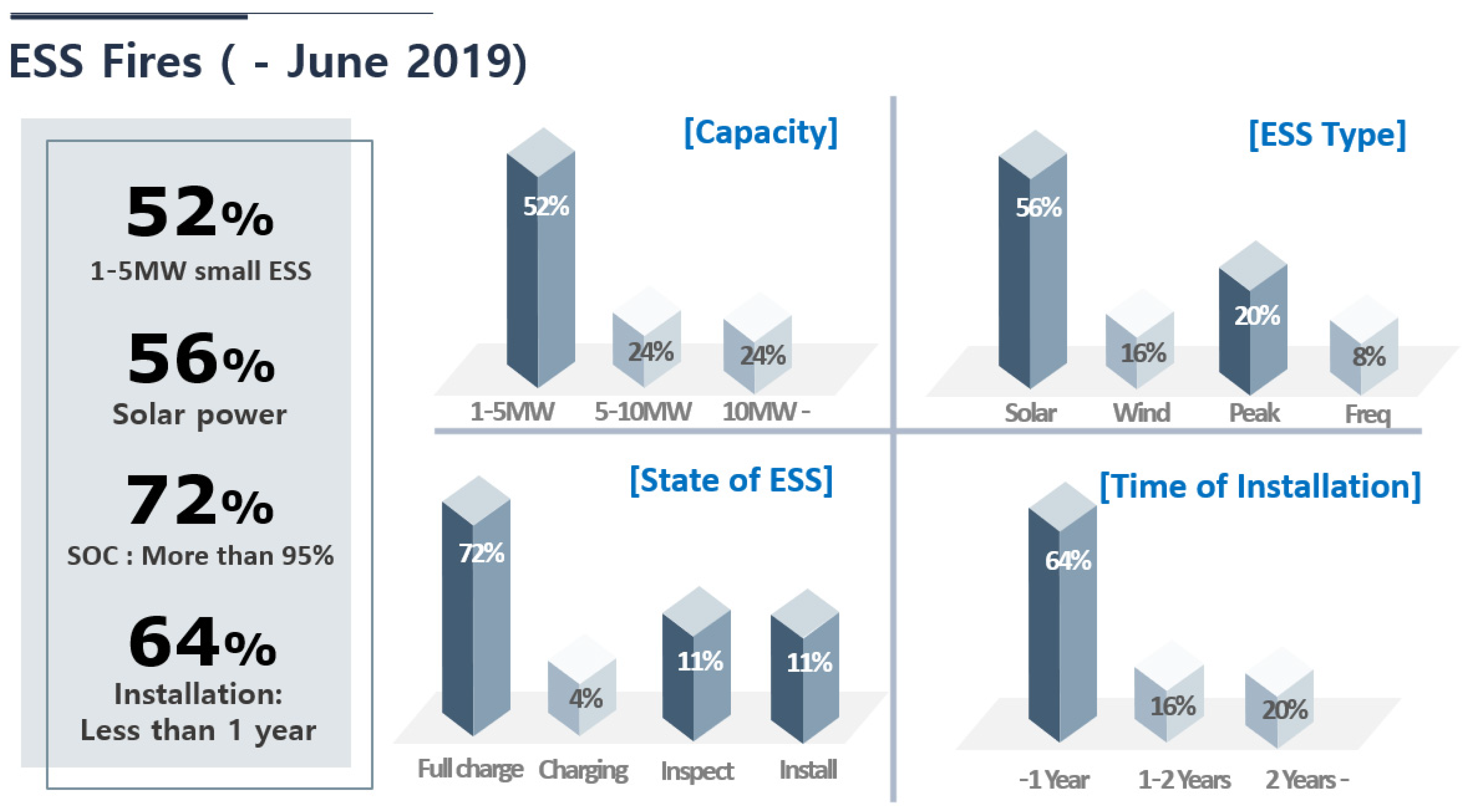
2.1. Phase #1 (–June 2019, 23 Cases)

According to statistics from 23 ESS fires in South Korea prior to June 2019 presented in Figure 1, a significant proportion of ESS fires broke out in small systems with a capacity of 1–5 MW, accounting for 52% of the total. Additionally, large ESSs with a capacity of 10 MW or more accounted for 24% of the incidents. In terms of ESS applications, solar power accounted for 56% of the total, peak load for 20%, wind power for 16%, and frequency correction for 8%. It is worth noting that the proportion of solar power to small ESSs is comparable as most solar power systems possess a relatively small ESS capacity. Furthermore, ESS fires that occurred within one year after installation accounted for 64% of the total. In the case of older ESSs that experience fires, a correlation with the lithium-ion battery lifespan may be considered; however, when an ESS aged less than one year experiences a fire, the exact cause is unknown, but it may be due to operating under harsh conditions or design flaws. Moreover, ESS fires were observed to occur when the SOC was over 95%, accounting for 72% of the total. Notably, in the case of solar energy, ESS fires broke out after 5 p.m. when the charging process had been completed, and in the case of peak load, ESS fires broke out at dawn when the charge was completed. This may be attributed to the increased likelihood of fire when the lithium-ion battery is in a high-level energy state, as it is a characteristic of this type of battery [].
Figure 1. Status of ESS fires in Phase #1.

2.2. Phase #2 (June–October 2019, 5 Cases)

Despite the findings and fire prevention measures established through the fire investigation of Phase #1, a subsequent series of five additional ESS fires prompted the formation of a government-appointed fire investigation committee to investigate the incidents shown in Figure 2. An examination of the data presented in Table 1 revealed that four out of the five ESS fires in Phase #2 occurred when the SOC was at 95% or higher. Therefore, the committee focused its investigation on analyzing the relationship between the battery’s SOC and ESS fires, specifically in regard to lithium-ion batteries in ESSs. To further explore the causes of the fires, the committee conducted a comprehensive examination, including an ESS fire site survey, a survey of similar ESS sites, and an environmental analysis to identify the underlying cause of the fires.
Figure 2. ESS fire statistics by region in South Korea.
Table 1. Status of ESS fires in South Korea.

3. Fire Investigation

The recent increase in ESS fires, particularly those that have been installed for less than two years, has emerged as a significant challenge for ESS distribution policies. In response, the government promptly formed a committee to investigate these incidents. The committee was composed of approximately 20 experts in the fields of electricity, battery technology, and fire safety, and the investigation was conducted over the course of two years. However, due to the novel nature of ESS fires and the significant damage they can cause, the investigation was constrained by a lack of definite proof of the cause of ESS fires. To address this limitation, the committee proposed a special investigation to verify possible hypotheses of ESS fire causes. Through an analysis of ESSs and verification experiments, the committee examined four possible hypotheses. Despite the lack of definitive proof linking these hypotheses to ESS fires, the committee proposed the installation of an ESS data storage system which would continuously record data for future investigations of ESS fires. Subsequently, the ESS fire investigation in Phase #2 was conducted based on ESS data at the fire sites, which partially confirmed the possibility of fire cause and identified overall ESS fire characteristics.

3.1. Fire Investigation Committee (Phase #1)

In response to the occurrence of 23 ESS fires, the government organized a joint investigation committee comprising 20 experts to analyze the causes of these incidents. Despite the lack of definite evidence to explain the ESS fires, the committee utilized a methodology of hypothesis and verification to arrive at potential causes. Through expert discussion, the committee selected four representative hypotheses that were deemed to have a causal relationship and proceeded to verify these hypotheses through field investigations and experiments.
  • Lithium-ion battery cell fault.
  • Insufficient electrical surge protection system.
  • Ineffective environmental management and inadequate installation.
  • Absence of ESS integrated management system.

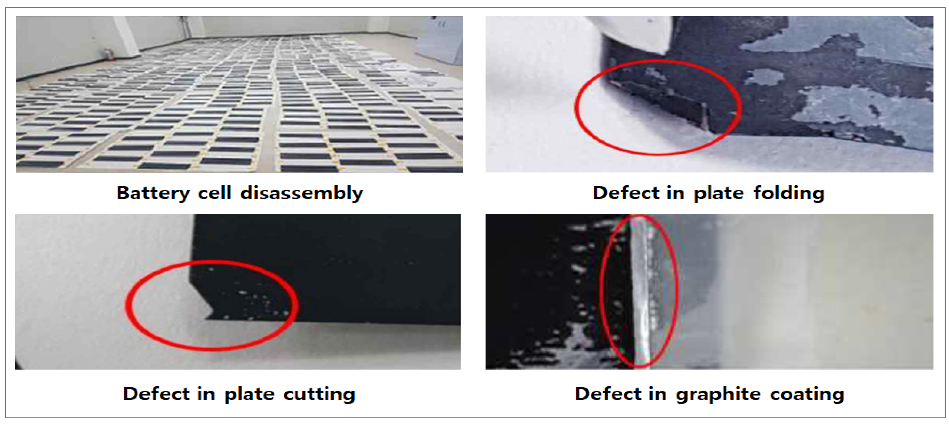
3.1.1. Lithium-Ion Battery Cell Fault

Upon identifying that some of the ESS fires had occurred in systems that utilized batteries produced by the same factory around the same time, the committee decided to conduct a comparative analysis on similar sites that had not experienced fires. Through an analysis of the disassembled battery cells from ESSs at these similar sites, the committee identified manufacturing defects such as plate folding, cutting defects, and graphite coating defects in some cells, as presented in Figure 3. These defects could potentially lead to partial shorts between plates. Depending on the degree of plate shorts, a battery cell could experience thermal runaway. To determine the causality between these manufacturing defects and the battery thermal runaway, the committee conducted repeated charging and discharging tests, simulating similar environmental conditions for over 180 cycles, but no inner short in the cell occurred that could lead to fire. In conclusion, although the defects identified through battery decomposition can lead to problems in battery performance, they are unlikely to be a direct cause of ESS fires.
Figure 3. Battery defects in energy storage system fires [].

3.1.2. Insufficient Electrical Surge Protection System

The committee conducted an experiment to verify the hypothesis of the danger of external electric surge as presented in Figure 4. To analyze the entire ESS, the experiment was conducted separately on the DC and AC parts of the system, using a method of short-circuiting the terminal or ground. The results of the experiment on the DC part of the ESS indicated that the external electric surge, such as a short circuit, may cause ESS fires. Moreover, the AC part of the ESS was found to be particularly vulnerable to external electric surges. It is possible for fires to occur in ESS when an external surge at the terminal is generated during experiments. However, since there were no concrete pieces of evidence indicating an external surge at the fire site due to heavy fires, it is impossible to establish a direct relationship between an external surge and the fires.
Figure 4. Fires in energy storage system module [].

3.1.3. Ineffective Environmental Management and Inadequate Installation

In an effort to investigate the potential relationship between poor management of the operating environment and ESS fires, an experiment, as presented in Figure 5, was conducted. The test simulated a one-day cycle, including full charge and discharge, under conditions of high humidity and dust within the ESS. The results of the test, which was conducted for more than one month, revealed no instances of ESS fires. It is worth noting that although a fire may have occurred had the experiment been conducted for a longer time period, there was no indication of low insulation resistance in the ESS; thus, a longer-term test was deemed unnecessary. Additionally, an experiment was conducted to investigate the potential impact of salt water mist on insulation resistance in the ESS. Due to the higher conductivity of salt water compared to pure water, it is easier to compromise insulation resistance. This can lead to a short circuit between the terminals of the ESS and fires in Figure 5. However, there was no evidence of salt water present, and all of the ESS fire sites were located in areas far from the sea.
Figure 5. An experiment under salt water conditions [].

3.1.4. Absence of ESS Integrated Management System

The investigation revealed that the manufacturers of EMSs, PMSs, and BMSs were different making it challenging to seamlessly link and operate them. In particular, it was found that errors may occur during communication between systems due to different time protocols used in EMSs, PMSs, and BMSs. Moreover, each system in the ESS has its own protective system that prevents ESS fires and surges. However, without an integrated management system, it is difficult to respond effectively to fires or emergency situations. Although the investigation results do not directly indicate the cause of ESS fires, it was identified as a risk factor that can exacerbate the likelihood of ESS fires.

3.2. Fire Investigation Committee (Phase #2)

As can be seen from Table 2, despite the implementation of fire prevention measures outlined in the findings of the initial investigation committee (Phase #1), an additional five ESS fires occurred. In response, a second investigation committee (Phase #2) was formed to further investigate these incidents. Four of the five ESS fires occurred when the SOC was 95% percent or higher, as shown in Table 1. Therefore, the Phase #2 committee focused its investigation on lithium-ion batteries to determine any potential correlation between the battery’s SOC and the occurrence of fires. In addition, a fire site survey, a survey of similar sites, and an environmental analysis were conducted to ascertain the specific causes of the fires.
Table 2. Energy storage system fire status in Phase #2.

3.2.1. ESS Fire Site Investigation

The investigation was conducted using a combination of ESS data analysis and evidence analysis collected from ESS fire sites. Upon the examination of the time synchronization data from BMSs, EMSs, and PCSs, it was determined that a time error existed. This error was attributed to the use of BMSs, EMSs, and PCSs from different manufacturers, which limited the ability to determine the chronological order of events occurring within each system. To address this issue, the investigation proceeded by synchronizing the time of each system while examining the voltage and current values of the cells and modules. The data analysis revealed that ESS fires tend to originate from specific batteries, rather than occurring simultaneously on multiple batteries.
Essentially, the BMS has to control charge and discharge based on the voltage and temperature of the battery. However, we found a critical issue related to the performance of the BMS. According to the BMS log data obtained from ESS fires, it was found that the time at which the battery’s low voltage occurred preceded the time at which the battery’s temperature rapidly increased. Further analysis determined that this time difference was likely because the BMS collected voltage data from all batteries, whereas temperature data was only collected at the center of two points in the battery module containing multiple batteries, as depicted in Figure 6. Furthermore, it was determined that if thermal runaway occurred in cell #1, the signals of V0 and V1 would be cut off, but there would be no change in temperature T1. This is because it was assumed that the initial thermal runaway always takes place in a specific battery, taking at least 90 s to transfer to the next battery. Therefore, it was estimated that it would take at least 150 s to detect high temperatures after the initial thermal runaway occurred.
Figure 6. The energy storage system module ((a) front, (b) side, and (c) structure).
The investigation into the origin of the ESS fire was conducted through a comprehensive analysis of the BMS data, in conjunction with a thorough examination of the evidence and phenomena observed at the site of the fire. The results of the analysis indicated that the fire originated from a specific battery and subsequently spread to other batteries, resulting in a rapid escalation of the fire. Despite the thorough investigation, it was determined that identifying a singular case for thermal runaway in lithium-ion batteries is challenging due to the limitations of available evidence having been damaged by the fire. Moreover, it was found that proving the existence of defects in the product through the examination of this damaged evidence is also challenging.

3.2.2. Investigation of Similar ESS Sites

To differentiate the causes of ESS fires, we conducted an investigation at similar ESS sites that utilized batteries manufactured at the same time. Our findings revealed that some batteries exhibited low voltage in the BMS data: specifically, a deviation in voltage between the MAX and MIN cells of approximately 50 mV, as depicted in Figure 7. Although this deviation value falls within acceptable levels, it exceeded the typical deviation of 30 mV observed in normal ESSs. We hypothesized that the MIN cell may have been a contributing factor to ESS fires. To test this hypothesis, two charge and discharge cycles per day were conducted on the selected MIN cell from similar sites for a one-month period, but no fires were observed, nor were there any indications of voltage drops or insulation issues in the MIN cell.
Figure 7. The battery voltage graph for ESS-like site.

3.2.3. ESS SOC Analysis

In response to ESS fires that occurred prior to June 2019, the government recommended that ESS SOCs be maintained at less than 80% (Upper limit of SOC) until the cause of the fires could be clearly identified. Nevertheless, data analysis, as presented in Table 3, revealed that in the case of the Yesan ESS fire, the upper limit of SOC was raised from 70% to 95% eight days before the fire. Similarly, for the ESS fire in Pyeongchang, the upper limit increased from 95% to 100% fourteen days prior to the fire outbreak. In the case of the Gunwi ESS fire, the upper limit was raised from 70% to 95%, five days before the fire. Additionally, in violation of government guidelines regarding the upper limit of SOC, the Hadong and Gimhae fires occurred at SOCs of 95%.
Table 3. The state of charge status in energy storage system fires.

3.2.4. Results

The investigation conducted at the ESS fire sites (Yesan, Pyeongchang, Gunwi, and Gimhae) revealed that a rapid voltage drop and temperature increase in specific cells and modules were detected according to the BMS log data. The cause of the fire at the Hadong site was determined to be a short circuit caused by external unknown material contact between the positive and negative terminals. In contrast, at the other four sites, the fires occurred while the SOC was over 95%, in violation of government guidelines to maintain SOC levels below 80%. It was determined that the ESS fires originated from thermal runaway in a particular cell and rapidly propagated to other cells or modules. The cause of the thermal runaway remains unknown, but it is speculated that it may have been caused by dendrites generated by battery faults or high-temperature stress. Subsequently, it was recommended that charging rates be lowered to SOC levels between 80% and 85% to prevent fires and that operating record storage devices be installed in both new and existing ESSs to prevent accidents and identify the cause of any future fires.

4. ESS Fire Characteristics

4.1. SOC (−95%)

The results of the analysis of the ESS fires in Phase #1 and Phase #2 indicate a correlation with the SOC. Out of a total of 23 fires, 18 cases of ESS fires in Phase #1 took place when the SOC was either at the end of charge or higher than 95%, which constitutes approximately 78% of the total fires. The analysis suggests that ESS fires in Phase #2 occurred when the SOC was 95% or higher, with the exception of the Gunwi case. However, it should be noted that the Gunwi ESS site had been operated at an SOC level of 95% for 5 days prior to the fire, suggesting that elevated SOC levels may exert stress on the ESS.

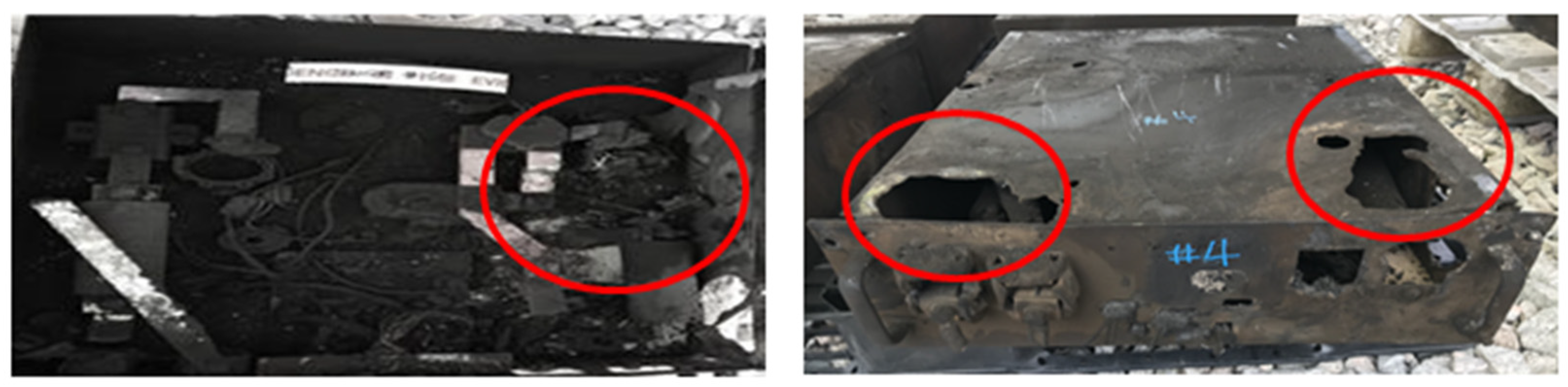
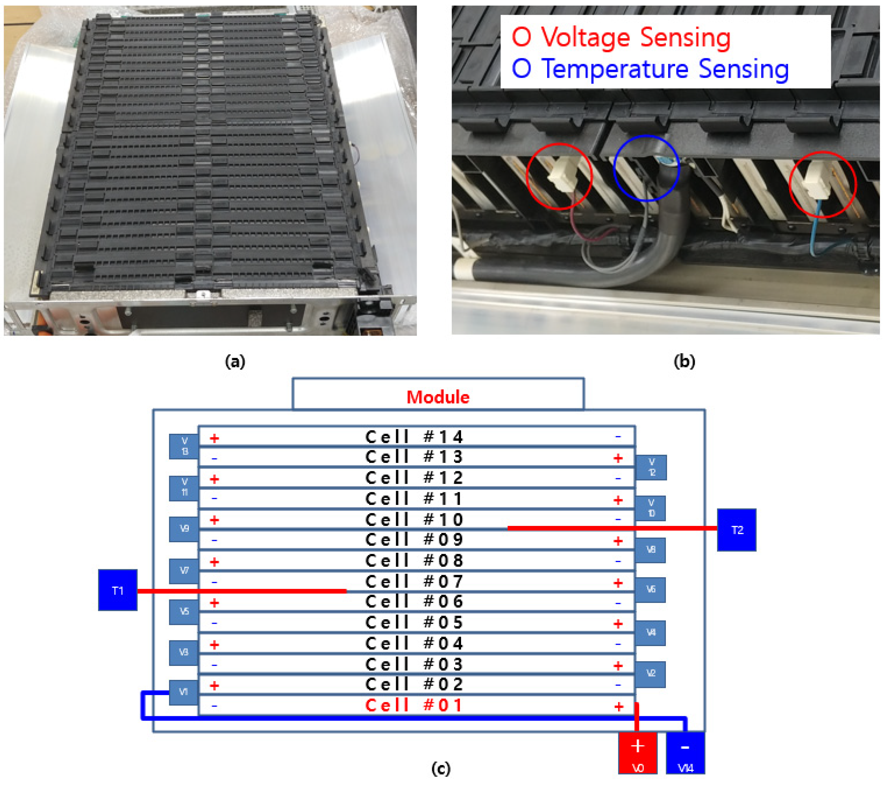
4.2. ESS Fires Originating in a Particular Cell
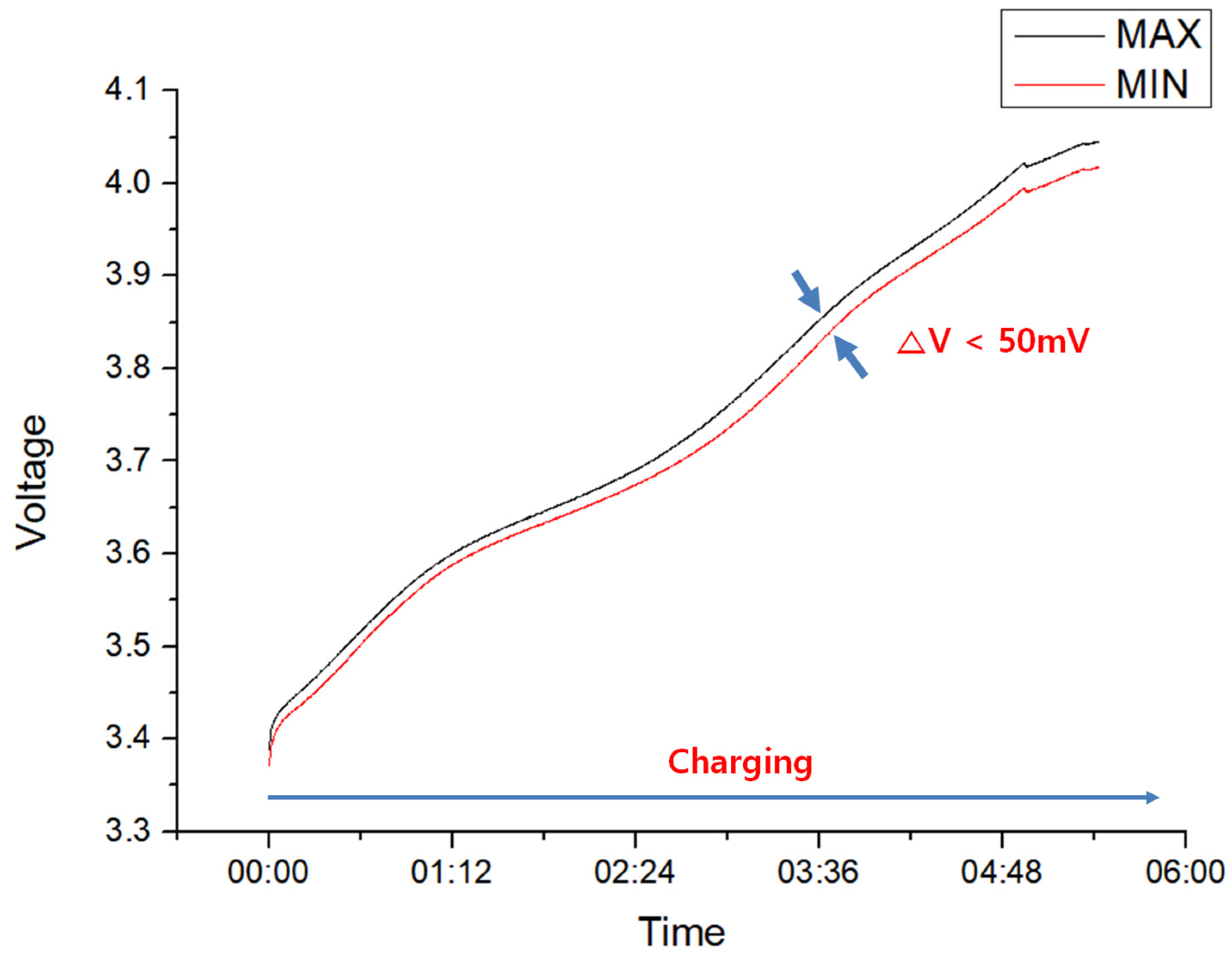
In the initial phase of the ESS fires investigation (Phase #1), the BMS log data were either damaged or not recorded due to the fire, and the exact location of the fire could not be determined. However, in the subsequent phase of the investigation (Phase #2), the exact location of the fire was confirmed through the implementation of safety measures, specifically the storage of BMS log data in a secure location. The BMS records critical information regarding the battery’s condition including voltage, temperature, SOC (state of charge), and SOH (state of health), among other aspects, as depicted in Figure 8. An analysis of the BMS log data, including cell voltage and module temperature, allowed for the identification of several characteristics associated with ESS fires. The occurrence of thermal runaway caused a drop in voltage in the BMS data, resulting in a decrease in cell voltage from the normal state (4.2 V) to near 0 V. The maximum value of noise is the total module voltage, as shown in Figure 9. This suggests that ESS fires tend to occur in a particular cell during charging and discharging cycles and can then spread to other cells over time, as evidenced by the identification of multiple voltage drops.
Figure 8. Battery management system log data type in energy storage system.
Figure 9. Battery voltage graph at first thermal runaway.

4.3. Overcurrent

Thermal runaway in ESS fires can result in the destruction of the insulation of cells or modules, leading to the formation of short circuits and an overcurrent within the ESS. This increase in current flow can cause melting of the current fuse or wires connected between modules, as illustrated in Figure 10. Typically, the capacity of the fuse used in a battery module is designed to be approximately 20 times the capacity of the battery in order to prevent short-circuit current from occurring in the event of a short circuit within the battery module. However, if a fire causes an abnormal conductive path, a short-circuit current will flow regardless of the presence of the fuse, causing the melting of the wires and terminals. The thermal effect of thermal runaway can propagate from one cell or module to another, and the presence of an overcurrent can further accelerate this process.
Figure 10. (a) Current fuse in energy storage system module, (b) melted fuse at the fire site and (c) melting of wires connected between modules.

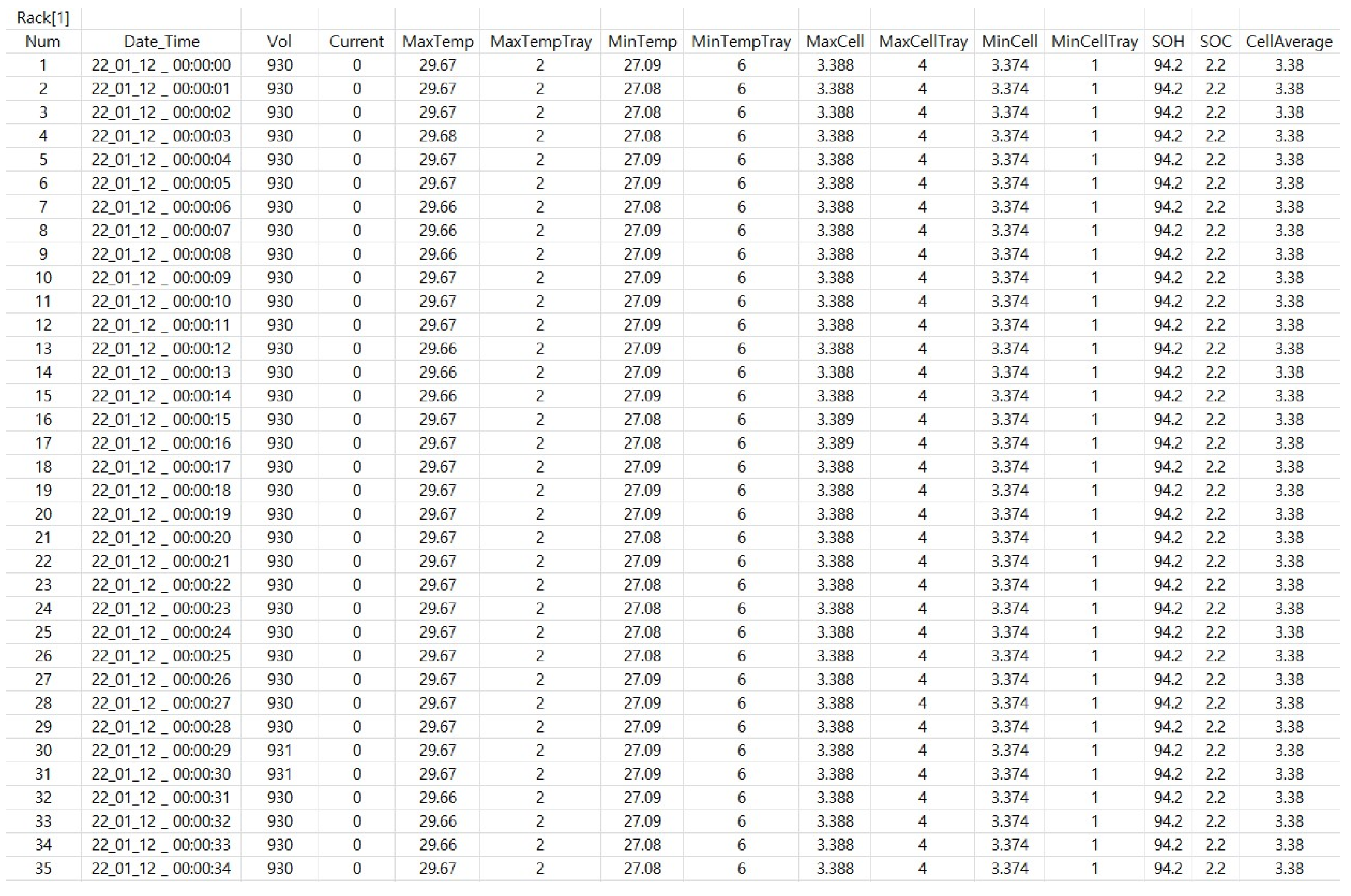
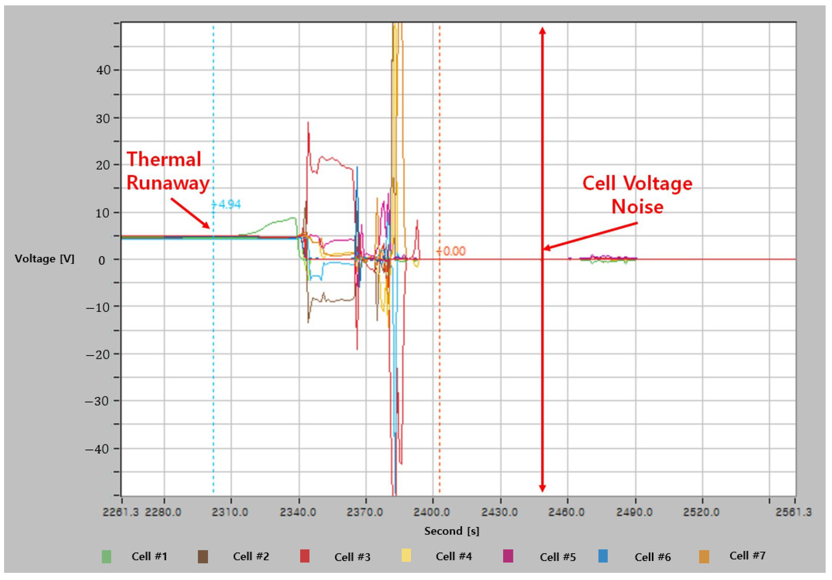
4.4. Noise from BMS Log Data

The BMS serves the purpose of collecting and processing data such as cell voltage, module temperature, and diagnostic codes, and transmitting log data to the main system located in the battery room or another site connected via a network. Specifically, in cases where the main system is located in a battery room, it is designed to withstand fire. BMSs have numerous wires for monitoring the battery state, including measuring cell voltage by electrically connecting all battery terminals to the BMS, and measuring module temperature using a thermal coupler that varies its resistance value based on temperature. Therefore, to connect the numerous wires and the thermal coupler, the BMS requires a connector composed of several pins. However, the narrow pin gap of the connector makes it vulnerable to short circuits in the event of an ESS fire. As observed in investigations of ESS fires, the BMS was frequently damaged by both thermal and electrical effects, with the connector being particularly susceptible to severe damage as depicted in Figure 11. This damage resulted in the generation of noisy data due to short circuits between the connector pins. Since each pin is electrically connected and they each have a certain voltage level, a short circuit in the BMS can result in a measurement of the maximum voltage of the module, which is not a real reflection of the cell voltage but rather noise generated by the BMS during the ESS fire. In the aftermath of the initial thermal runaway the BMS generates a noise value, with the maximum noise voltage reaching a value similar to the module voltage, as shown in Figure 12.
Figure 11. (a) Battery management system (BMS) circuit, (b) BMS circuit at energy storage system fire site, and (c) X-ray photograph of the BMS circuit.
Figure 12. Error in battery management system log data.

4.5. Structure Collapse

In the event of a thermal runaway within a lithium-ion battery, various gases are generated. As the temperature rises, combustible gases and oxygen are produced, as illustrated in Figure 13. Additionally, the formation of hydrofluoric acid, which poses a risk to human health and safety, particularly for firefighters, is observed. The increase in the volume of generated gases leads to a corresponding increase in the internal pressure of the ESS battery room. Moreover, the deflagration of combustible gases in the battery room may easily occur. Nevertheless, to mitigate the risk of fire, a gas fire extinguisher is installed in the battery room. However, the deflagration and activation of the extinguisher can result in a rapid increase in the internal pressure, potentially leading to structural collapse. This is exemplified in Figure 14 and Figure 15, which depict a site where the battery room collapsed due to deflagration and internal pressure buildup during a fire. On 19 April 2019, this phenomenon (deflagration) resulted in injury to a firefighter at an ESS fire site in Arizona, highlighting the importance of considering the potential consequences of thermal runaway and the importance of adequate protective measures [,].
Figure 13. Li-ion battery thermal runaway generated gas [].
Figure 14. Gunwi energy storage system fire site.
Figure 15. Arizona energy storage system fire site [].

5. Conclusions

The investigation committee uncovered certain characteristics of ESS fires. Due to the extensive damage at the fire sites, there was a lack of sufficient evidence to determine the exact cause of these fires. Nonetheless, the method used for investigating fire sites and testing hypotheses was found to be effective. The study findings showed that most ESS fires occurred when the SOC was at or above 95%. The data collected from the BMS log during the ESS fires revealed that the fires often originated from a thermal runaway in a particular cell and then spread to nearby cells. Although the root cause of the ESS fires remains elusive, the investigation committee believes that analyzing the voltage and temperature data in the BMS logs of ESSs will provide valuable information for preventing future ESS fires.

Author Contributions

Conceptualization, J.-W.J. and Y.-U.N.; methodology, Y.-U.N.; formal analysis, Y.-U.N.; investigation, Y.-U.N.; writing—original draft preparation, Y.-U.N.; writing—review and editing, J.-W.J.; supervision, J.-W.J. All authors have read and agreed to the published version of the manuscript.

Funding

This research received no external funding.

Data Availability Statement

The data used in this study are available from the corresponding author upon reasonable request.

Acknowledgments

We thank the anonymous reviewers for their constructive feedback.

Conflicts of Interest

The authors declare no conflict of interest.

References

  1. Sun, C.; Negro, E.; Vezzù, K.; Pagot, G.; Cavinato, G.; Nale, A.; Herve Bang, Y.H.; Di Noto, V. Hybrid inorganic-organic proton-conducting membranes based on SPEEK doped with WO3 nanoparticles for application in vanadium redox flow batteries. Electrochim. Acta 2019, 309, 311–325. [Google Scholar] [CrossRef]
  2. Sun, C.; Zhang, H. Review of the development of first-generation redox flow batteries: Iron-chromium system. ChemSusChem 2022, 15, e202101798. [Google Scholar] [CrossRef]
  3. Victoria, M.; Zhu, K.; Brown, T.; Andresen, G.B.; Greiner, M. The role of storage technologies throughout the decarbonisation of the sector-coupled European energy system. Energy Convers. Manag. 2019, 201, 111977. [Google Scholar] [CrossRef]
  4. Serrano-Canalejo, C.; Sarrias-Mena, R.; García-Triviño, P.; Fernández-Ramírez, L.M. Energy management system design and economic feasibility evaluation for a hybrid wind power/pumped hydroelectric power plant. IEEE Lat. Am. Trans. 2019, 17, 1686–1693. [Google Scholar] [CrossRef]
  5. Abrell, J.; Kosch, M. Cross-country spillovers of renewable energy promotion-The case of Germany. Resour. Energy Econ. 2022, 68, 101293. [Google Scholar] [CrossRef]
  6. Ibrahim, H.; Ilinca, A.; Perron, J. Energy storage systems-characteristics and comparisons. Renew. Sustain. Energy Rev. 2008, 12, 1221–1250. [Google Scholar] [CrossRef]
  7. Olabi, A.G.; Onumagebu, C.; Tabbi, W.; Mohamad, R.; Mohamad, A.; Abdul, H. Critical review of energy storage system. Energy 2021, 214, 118987. [Google Scholar] [CrossRef]
  8. Deepika, V.; Ankit, B. Thermal Behavior of Lithium-and Sodium-Ion Batteries: A Review on Heat Generation, Battery Degradation, Thermal Runway-Perspective and Future Directions. Energy Fuels 2022, 36, 14000–14029. [Google Scholar]
  9. Vijay, S.; Kevin, M.; Quinn, H. Quantification of Combustion Hazards of Thermal Runaway Failures in Lithium-Ion Batteries. SAE Int. J. Altern. Powertrains 2014, 3, 98–104. [Google Scholar]
  10. Dongxu, O.; Jiahao, L.; Mingyi, C.; Jian, W. Investigation into the Fire Hazards of Lithium-Ion Batteries under Overcharging. Appl. Sci. 2017, 7, 1314. [Google Scholar]
  11. Kai, Z.; Lu, W.; Chenbo, X.; Hejun, W.; Dongmei, H.; Kan, J.; Xiaomeng, X. Study on Thermal Runaway Risk Prevention of Lithium-Ion Battery with Composite Phase Change Materials. Fire 2023, 6, 208. [Google Scholar]
  12. Ghassan, Z.; Rodolfo, D.; Monica, C.; Guzay, P. The lithium-ion battery: State of the art and future perspective. Renew. Sustain. Energy Rev. 2018, 89, 292–308. [Google Scholar]
  13. Chen, S.; Huaiguo, W. Research on the Technological Development of Lithium Ion Battery Industry in China. J. Phys. Conf. Ser. 2019, 1347, 012087. [Google Scholar]
  14. Electrical Energy Storage; White Paper; International Electrotechnical Commission: Geneva, Switzerland, 2011; pp. 17–30.
  15. Matthew, T.L.; Bharatkumar, S.; Paul WC, N.; Sumitava, D. Battery Energy Storage System (BESS) and Battery Management System (BMS) for Grid-Scale Applications. Proc. IEEE 2014, 102, 1014–1030. [Google Scholar]
  16. Seongyun, P.; Jeongho, A.; Taewoo, K.; Sungbeak, P.; Youngmi, K.; Inho, C.; Jonghoon, K. Review of state-of-the-art battery state estimation technologies for battery management systems of stationary energy storage systems. J. Power Electron. 2020, 20, 1526–1540. [Google Scholar]
  17. Faisal, A.; Lars, J.; Bo, E. Simultaneous Thermal and State-of-Charge Balancing of Batteries: A Review. In Proceedings of the IEEE Vehicle Power and Propulsion Conference, Coimbra, Portugal, 27–30 October 2014. [Google Scholar]
  18. Mina, N.; Phillip, K.; Ali, E. Lithium-Ion Battery Pack Robust State of Charge Estimation, Cell Inconsistencey, and Balancing: Review. IEEE Access 2021, 9, 50570–50582. [Google Scholar]
  19. Michael, D.; Bin, W.; Alireza, K. Design and optimization of a solar power conversion system for space applications. IEEE Trans. Ind. 2019, 55, 2310–2319. [Google Scholar]
  20. Na, K.-S.; Lee, J.; Kim, J.-M.; Lee, Y.-S.; Yi, J.; Won, C.-Y. Power Conversion System Operation Algorithm for Efficient Energy Management of Microgirds. Electronics 2021, 10, 2791. [Google Scholar] [CrossRef]
  21. Mingyi, L.; Xi, C.; Chuanzhao, C.; Pengcheng, W.; Chengrui, W.; Jie, P.; Haodong, L.; Xinyu, J.; Rui, L.; Jianlin, L. A Review of Power Conversion Systems and Design Schemes of High-Capacity Battery Energy Storage Systems. IEEE Access 2022, 10, 52030–52042. [Google Scholar]
  22. Saima, A.; Yogesh, S.; Viktor, K. Energy management systems: State of the art and emerging trends. IEEE Commun. Mag. 2013, 51, 114–119. [Google Scholar]
  23. Younes, Z.; Ibrahim, A.; Saad, M.; Reyasudin, B.K.M.; Mehdi, S.; Alex, S.; Ben, H. Energy Management System in Microgrids: A Comprehensive Review. Sustainability 2021, 13, 10492. [Google Scholar]
  24. Russo, P.; Longobardo, G.; Mazzaro, M.; Di Bari, C.; Cancelliere, P. Fire Behavior of NMC Li-ion Battery Cells. In Proceedings of the Ninth International Seminar on Fire and Explosion Hazards, St. Petersburg, Russia, 21–26 April 2019; pp. 881–890. [Google Scholar]
  25. Ministry of Trade, Industry and Energy of South Korea. The Result of the First ESS Fire Accident Investigation; Sejong, Republic of Korea, 2019.
  26. Scott, B. McMicken Battery Energy Storage System Event Technical Analysis and Recommendations; Document No.:10209302-HOU-R-01, Issue: A, Statis: Final; Arizona Public Service: Chalfont, PA, USA, 2020. [Google Scholar]
  27. Mark, B.; DeCrane, M.S. Stephen Kerber Four Firefighters Injured In Lithium-Ion Battery Energy Storage System Explosion–Arizona; UL Firefighter Safety Research Institute: Columbia, MD, USA, 2020. [Google Scholar]
  28. Weifeng, L.; Shun, R.; Yang, X.; Zhenhai, G.; Yupeng, C.; Hewu, W.; Minggao, O. Fire boundaries of lithium-ion cell eruption gases caused by thermal runaway. iScience 2021, 24, 102401. [Google Scholar]
Disclaimer/Publisher’s Note: The statements, opinions and data contained in all publications are solely those of the individual author(s) and contributor(s) and not of MDPI and/or the editor(s). MDPI and/or the editor(s) disclaim responsibility for any injury to people or property resulting from any ideas, methods, instructions or products referred to in the content.

Article Metrics

Citations

Article Access Statistics

Multiple requests from the same IP address are counted as one view.