1. Introduction
In tokamaks, a few percent of plasma current pulses can terminate uncontrollably in a form of the following fast events: either major disruptions (MD) or vertical displacement events, symmetric or asymmetric (VDE or AVDE). Each of these induces eddy currents in all conductive structures and changes currents in the windings of coils and, thus, applies pulsed EM loads to all conductive structures and changes loads to the coils. Many analysis teams, e.g., [
1,
2,
3], have simulated symmetric fast plasma events, MD and VDE, and calculated resultant EM loads, e.g., [
4,
5,
6]. In terms of net EM force balance, any fast plasma event causes a pulse of net EM force at the vacuum vessel with all in-vessel components, and a pulse of opposite net EM force at the coils with their structures [
7,
8,
9]. Below, we compact these long definitions into shorter terms: pulsed EM loads at “VV” and at “the Magnets”. Any fast EM event applies a pulse of vertical net EM force at VV and exactly opposite net force at the Magnets; however, the only asymmetric event, AVDE, causes also significant net lateral EM loads (forces and torques) at VV and all opposite at the Magnets. Many EM analysis teams have calculated accurate-enough patterns and waveforms of axially symmetric (thus, producing only net vertical forces) VDE-induced EM loads at VV and the Magnets. All outcomes in terms of symmetric VDE-induced loads are in a good mutual match; thus, they are not discussed in this article. Several teams, e.g., [
8,
9,
10] developed physical understanding and models for calculation of lateral AVDE-induced EM load components, and compared these with tokamak experiments. These models seriously differ from one another by assumptions on plasma evolution in a course of AVDE; thus, they suffer from a serious scatter of results in terms of lateral EM loads. Such scatter spans by an order of magnitude. Some models, e.g., [
8], derive the dominant component of lateral loads from interaction of the toroidally asymmetric poloidal halo current in VV with toroidal magnetic field, while others, e.g., [
9,
10], concentrate an attention on helical distortions of plasma current prior appearance of large halo current and, accordingly, on asymmetric patterns of VV eddy currents causing lateral loads. Experiments show that all fast EM events, and especially AVDE, do evolve somewhat differently, which makes each subsequent event unique, never repeating previous events. This gives an idea to attack the practical task of calculation of AVDE loads in a manner of parametric study, detailed below. The practical task is to obtain detailed time-dependent patterns of AVDE-induced distributed EM loads at VV (with all internals) and the Magnets (all coils and Cryostat) needed as inputs for the development and testing of relevant Tokamak Systems Monitoring (TSM) algorithms. TSM algorithms are fed by appropriate sensor data and deliver concise engineering information to the tokamak operator on actual behavior and status of all tokamak systems. When the described here family of practical AVDE models will converge in the single practical model, it will serve also as a part of the tokamak simulator.
This article explains a previously unreported practical approach based on the separation of routine straightforward calculations of AVDE-induced lateral EM loads from naturally uncertain multidisciplinary simulations of gradually growing plasma distortions at AVDE. In a gradual transition from VDE to AVDE, asymmetric plasma distortions usually resemble evolution of the kink modes [
8,
9,
10]. These modes grow firstly at plasma periphery, mostly in the “halo layer”, where plasma current intercepts the first wall. A loop of the halo current closes partly helically through the Halo layer, and partly through VV and in-vessel components. In terms of basic conservation laws, halo current results mostly from compression of toroidal magnetic flux frozen in the plasma.
Suggested here, the EM model works in a manner of parametric study. For parametrically varied input assumptions on a shape, scale, and a rate of the growing asymmetric distortions of the halo current, it delivers time-dependent patterns of asymmetric AVDE-induced EM loads in all structures and coils. These time-dependent patterns conclude in waveforms of all 3 + 3 orthogonal vectors of net EM forces and torques for VV and all opposite vectors at the Magnets. This article shows a number of first results, and later more complete parametric results will form a library of ready-for-use patterns and waveforms of lateral AVDE-induced EM loads. This library will allow pick-up ready-for-use lateral EM loads, in forms of detailed time-dependent patterns and waveforms of net loads, within a wide range of parametrically varied inputs. The tokamak physics community will advise which variants in this library are the closest to present understanding on the worst (in terms of lateral EM loads), but still possible, scenarios of AVDE evolution.
The EM model of AVDE described here employs and further develops the engineering logic based on generic conservation laws, as was highlighted by ITER EDA team [
11,
12].
2. New Model Approach Uses Superposition of Symmetric and Anti-Symmetric Halo Current Components
The main new feature of the proposed here model approach for calculation of AVDE-induced EM loads is in superposition of two time-dependent patterns of halo currents: (a) axially symmetric and (b) perfectly anti-symmetric. The first pattern comes from outputs of almost any presently available VDE simulation or VDE post-processing, and the second pattern is to be built and added as parametrically varied model assumption.
The axially symmetric component of the halo current employs one of the pre-existing outputs of VDE simulation (“pre-existing VDE model”), on condition that they do match the following:
- -
Obey a balance of net vertical EM forces between VV and Magnets (zero net for tokamak);
- -
Properly simulate evolution of toroidal and poloidal magnetic fluxes linked with the plasma.
By definition, the symmetric component of halo currents does not cause noticeable net lateral EM loads between VV and the Magnets. This is true for tokamaks with sufficiently symmetric conductive structures. Here we do not consider tokamaks with significant asymmetry of conductive parts, which themselves can cause significant net lateral EM loads between VV and the Magnets even at symmetric EM event, MD or VDE.
With the conditions listed above met by the symmetric component of the halo current, we build an additional EM model of a perfectly anti-symmetric halo current component obeying the following generic conservation laws on its own, and after superposition with the symmetric component.
A perfectly anti-symmetric halo component itself, and after superposition with the symmetric Halo component, shall:
- (a)
Assure balance of net EM loads (“zero total for the entire tokamak at any time instance”) not only for vertical EM forces, but also in terms of 3D EM loads (forces and torques) with significant lateral vectors, that means in terms of all 3 + 3 = 6 vectors of net EM forces and torques applied at VV and Magnets;
- (b)
Preserve waveforms of poloidal and toroidal magnetic fluxes linked with plasma as they already simulated with symmetric VDE model (e.g., [
2]), that means the anti-symmetric halo current component itself is to be built in such a way that it assures zero toroidal and poloidal magnetic flux linkages with the plasma;
- (c)
Do not disturb waveforms of net vertical EM forces applied at VV and the Magnets as they already obtained with symmetric VDE model, that means the anti-symmetric halo component itself shall be built in such a way that it causes zero net vertical EM forces at VV and the Magnets.
The next section illustrates a principle of configuration of the anti-symmetric halo current component satisfying all above-stated conditions and continue with practical numerical EM models of AVDE.
3. Conditions to Obey for the Shaping of Perfectly Anti-Symmetric Halo Current Component
The three above-listed conditions for errorless superposition of two halo current components leave not too many options for selection of the specific shape of the perfectly anti-symmetric halo component.
The time-dependent anti-symmetric halo current component is to be introduced in such a way that its superposition with the symmetric halo component does not disturb the above-stated balances. The additional condition is that in superposition with the symmetric component, the anti-symmetric component shall create magnetic configuration resembling a kink mode. Depending on helicity of the preceeding VDE we are free to select which kink mode we would try to match: either m = 2; n = 1, or m = 1; n = 1; or intermediate between these two as experimentally observed in AVDE at some tokamaks.
A reader knows well that EM models used for the VDE post-processing procedure, e.g., [
4,
6], feature “virtual” conductive bridges aimed to close poloidal loops of halo currents (assure zero current divergence). Since poloidal halo currents result from compression of toroidal magnetic flux linked with plasma, these “virtual” bridges are usually built to wrap around plasma [
4], and the prescribed waveform of the halo current obeys a balance of toroidal magnetic flux in plasma volume. In other FE models [
6], these bridges locate between the plasma and the first wall surface, just to close the halo current loop. In any case, for the post-processing of VDE (symmetric event), these bridges are fed by only the poloidal component of halo currents taken from outputs of plasma simulation codes, e.g., from [
2], since toroidal halo current pattern is already included in the pattern of toroidal plasma current density in simulations of EM transients in poloidal fields. Advanced VDE post-processing models sometimes feature not one but several enclosed poloidal bridges, aimed to mimic time-dependent evolution of the Halo layer with gradual slipping of toroidal belts where the halo current intercepts the first wall [
6].
Similar to the above-described well-known VDE post-processing, the new, introduced in this section, EM model of the perfectly anti-symmetric halo current component shall also have bridges wrapping around the plasma as needed to close halo current loops and obey a balance of toroidal magnetic flux in plasma. However, unlike the post-processing for VDE, to reflect asymmetric plasma distortion at AVDE resembling a kink mode, each bridge intended for the anti-symmetric halo component shall carry both poloidal and toroidal halo current components. This means, to generate realistic patterns of all currents and transient magnetic fields, these bridges shall be built not poloidal but helical, with dimensions and helicity resembling dimensions and helicity of the Halo layer at some time instance. The initial trial model described here has a single layer of helical bridges matching location and helicity of the Halo layer approximately at the time when AVDE loads peak. Quite likely, future advanced AVDE EM models will have more than one layer of helical bridges with different dimensions and helicities, aimed to a better match with plasma evolution prescribed by plasma-physical simulations, and gradual slipping of the halo current injection belts.
The described modification of the bridges, from poloidal to helical, is the only difference between commonly used EM models for VDE post-processing and the new EM model of the perfectly anti-symmetric halo current component described here, intended for calculation of AVDE-induced lateral loads.
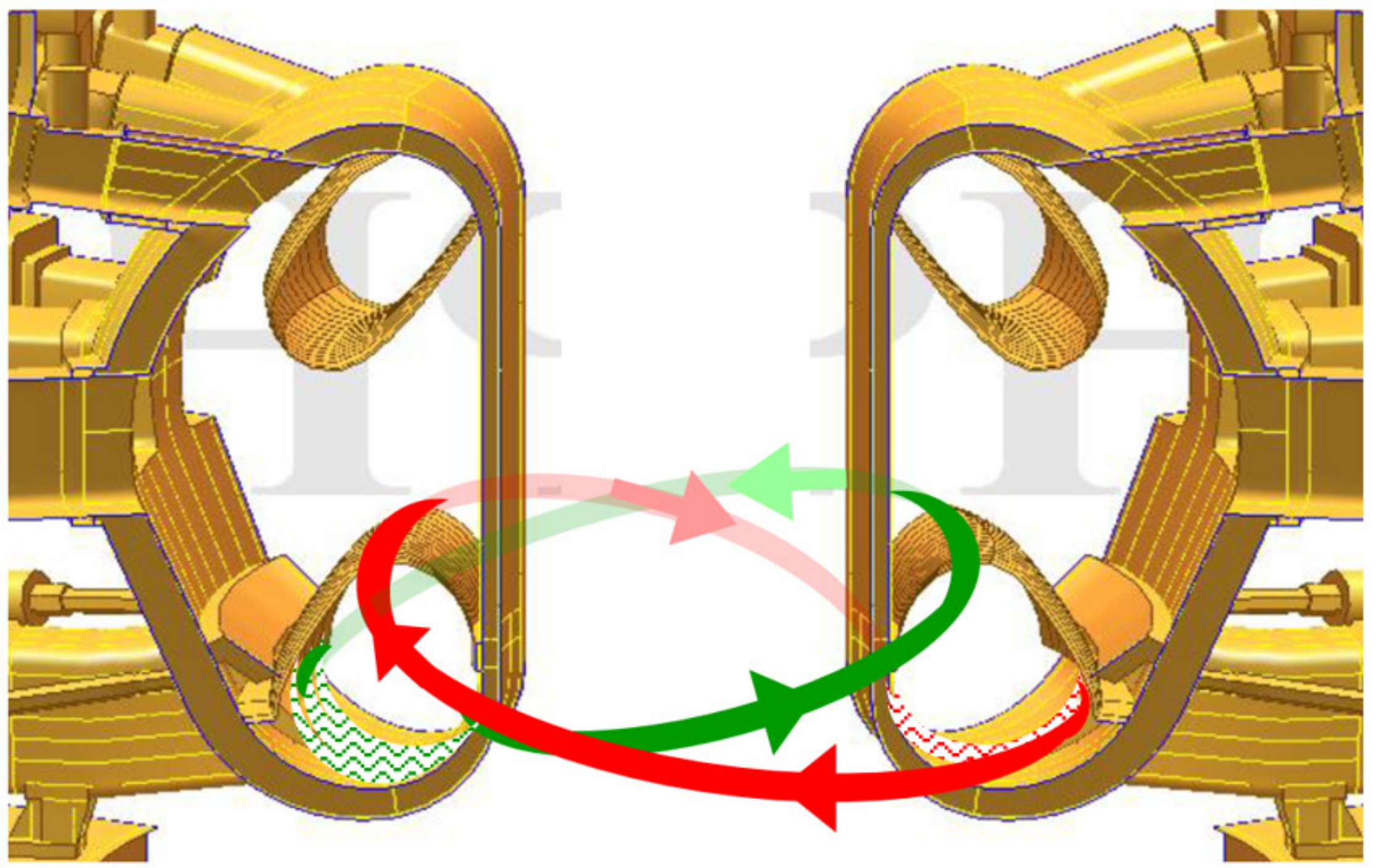
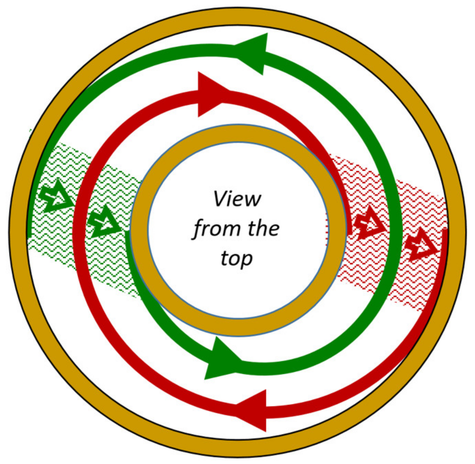
Figure 1 and
Figure 2 illustrate a principle of configuration of helical bridges for the perfectly anti-symmetric halo current component. To obey all abovementioned conditions and conservation laws, there should be at least a pair of identical helical bridges. In this pair, or in each pair, two bridges are to be spaced in toroidal direction by 180 degrees and fed by the “mirrored” current waveforms. These opposite waveforms shall vary in time identically in terms of the growing rate and current modulus. Current fed in each helical bridge forms a closed loop through VV with in-vessel components.
Figure 1 and
Figure 2 illustrate helical bridges by red and green arrows, and paths for closing of these currents through VV—simplistically by red and green dashed areas, when numerical simulations can deliver more realistic smooth patterns of halo currents in VV, blanket modules, and divertor panels.
To summarize, the basic idea of this AVDE model approach is the following: There shall be at least one pair of perfectly anti-symmetric helical bridges. Several such pairs may mimic a continuous Halo layer. Within each pair, two bridges locate at 180 degrees and carry always equal by modulus but opposite currents.
Below, we use term “helix” for the closed current loop formed by any one helical bridge and closed through VV as shown above. In each pair of helixes spaced by 180 degrees:
- -
One helix creates three net forces and three net torques at VV with internals, and opposite at the Magnets;
- -
Its “antipode” also creates three net forces and three net torques having exactly the same six moduli, some co-directional with, however others opposite to, the components created by the first helix.
The shape of the helixes is such that superposition of this EM model with the model of symmetric VDE creates magnetic configuration resembling the kink mode and producing all six net EM load components, including lateral EM load components (forces and torques), without duplication or omission.
Any bridges fixed in space, and especially bridges with fixed locations of halo current injection belts, of course, cannot perfectly imitate the evolving helicity of real plasma. However, two helical bridges forming one pair equally deviate from actual plasma helicity; thus, relevant model errors do compensate each other. Of course, we cannot say that peak lateral EM loads delivered by such a model will perfectly match real EM loads. However, we can say that this model is built in such a way that it intrinsically assures a good balance of net EM loads between VV (with internals) and the Magnets (with Cryostat). This is very important for input data serving the numerical simulation of the tokamak’s dynamic response to AVDE. Such an intrinsic match to generic conservation laws was built in earlier studies [
1,
3,
7]; however, they were not controlled in some recent studies. Thus, it is reminded by this article. With the AVDE model introduced above, the only source for non-zero residual net EM loads (forces and torques) at the tokamak as a whole is numerical errors accumulated by never-ideal FE simulations.
Reference [
8] has introduced the term “anti-symmetric halo current component” in a course of analytical decomposition of asymmetric current pattern in VV at AVDE. Thus we consider analytics in [
8] as perhaps the closest to the described here numerical models.
4. Basic FE Model of Tokamak Structures Serving for All Considered Here Variants of Bridges for the Anti-Symmetric Component of Halo Current
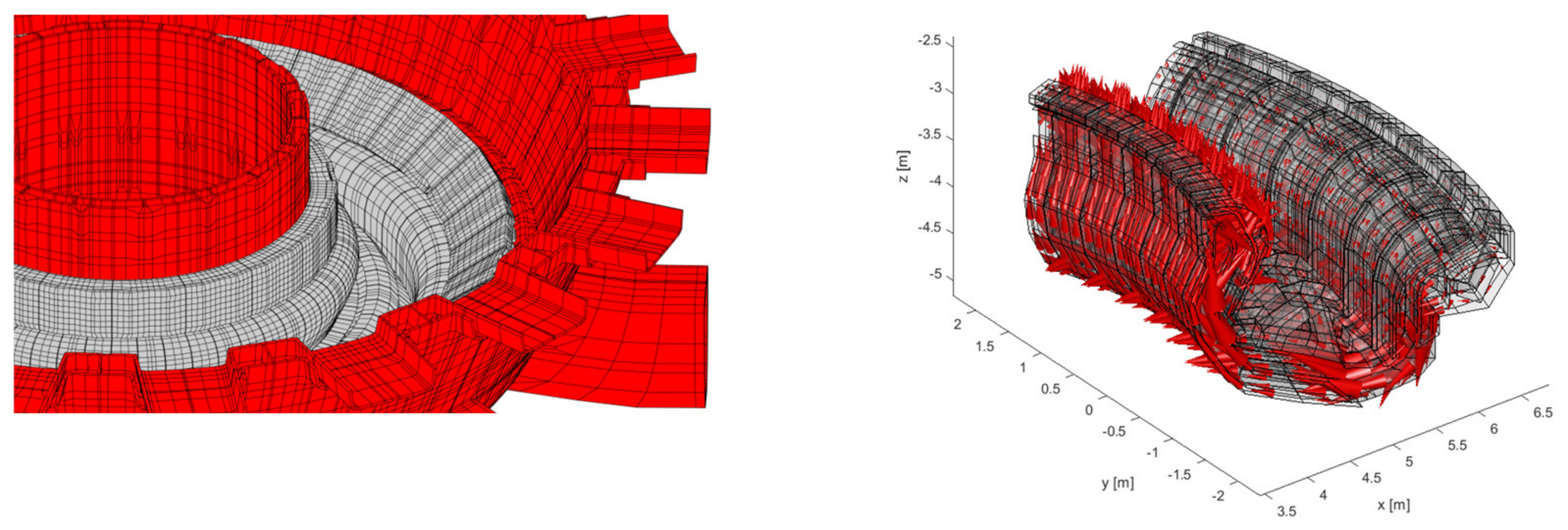
All results presented in this paper refer to the downward VDE in which the Halo layer intercepts divertor panels and the first wall in the divertor region. Hence, the computational model built for CARIDDI code [
5,
6] (
Figure 3) includes rather simplified mesh for the vacuum vessel with port stubs and port extensions, however more accurately meshed divertor area (including inner and outer vertical targets, the dome, the cassettes, with all relevant electrical connections) and the nearest rows of blanket modules, both at the inboard and outboard. In the toroidal direction, the model covers the whole torus. This was a challenge to adjust mesh density of such a 360-degree FE model to meet present computational capabilities. Typical mesh size in the divertor area is ~10 cm, while exterior VV diameter is approximately 20 m. This FE model takes approximately two days of computational time to simulate one EM transient.
Figure 3 shows some details of the finite elements’ mesh of the common part of FE model describing VV, blanket and divertor, and vectors of halo current density obtained at VDE (not for AVDE yet) at some time sample.
5. Model #1 of Bridges for the Perfectly Anti-Symmetric Halo Current Component
Model #1 has many common features with EM models commonly used for VDE post-processing because it employs the following additional simplifications. Having in mind that dominant components of lateral EM loads at VV are due to interaction of the poloidal halo current component in VV with the toroidal and poloidal external magnetic fields, helical bridges have been simplified (in the model #1) down to poloidal bridges located close to VV (between the plasma and VV).
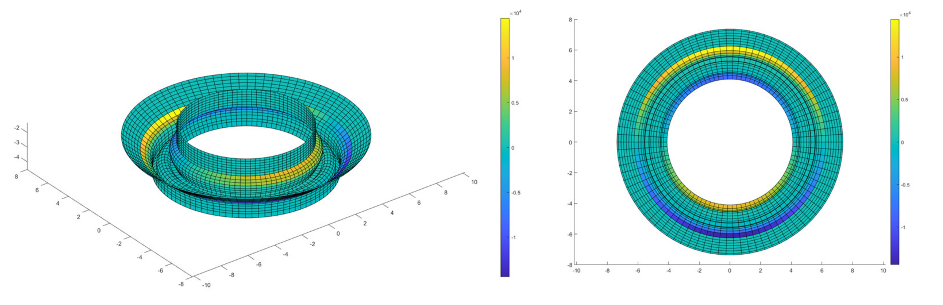
Figure 4 shows only poloidal bridges of the Model #1, when all other parts, common for all models compared here, have been shown in
Figure 3.
This model features multiple poloidal bridges located close to VV and fed by time-dependent net halo currents with harmonic modulation of its current density around the torus. This model does simulate the gradual slipping of halo current injection belts.
In the symmetric halo current component (that means still for “symmetric” VDE post-processing, not for AVDE yet), net halo current
is as follows:
where
is the poloidal length where toroidally symmetric halo current density
has the same sign (e.g., either entering in the wall or exiting from the wall),
s is a curvilinear coordinate along the poloidal direction, and
r is the radial coordinate.
In the anti-symmetric halo current component (for model #1), assuming here
m = 1,
n = 1, the net halo current
injected in the first wall along toroidal arc covering a half of the torus (
is:
where toroidally anti-symmetric halo current density
J_(
h,
A) (
s) is derived from the symmetric one by imposed harmonic modulation. In the opposite toroidal half of the torus, the injected anti-symmetric component of the halo current is the same by modulus, but has opposite direction.
Only in the Model #1, the poloidal location of anti-symmetric current injection (
Figure 4) evolves similarly to the one at the post-processing of symmetric VDE. Thus, it reproduces quite accurately the expected time-dependent relocation (“slipping”) of the plasma–wall contact in the poloidal plane. Then, along the toroidal arc, the current density of the anti-symmetric halo component at the injection areas is modulated as a sinusoid of the toroidal angle,
, here specifically at
n = 1, and multiplied by an arbitrarily selected scaling factor for peak current density
f.
The anti-symmetric halo current injection pattern depicted above allows analytical considerations on symmetry or anti-symmetry of two components of lateral forces acting at the vessel. The following analytical exercise is just for the Model #1 and for anti-symmetric loads at VV itself; however, we do keep in mind that opposite EM loads are applied to the Magnets.
The following analytical exercise assumes that density of the anti-symmetric halo current in VV has only two components,
since the current is assumed to flow in VV just in the poloidal direction at each toroidal angle. Given the
dependence of the injected halo current, for analytical estimates, we assume that:
The Cartesian
x-y-z components of current density are, hence, as follows:
Considering first the interaction of such current density with external toroidal field
:
the Cartesian components of the force density are:
Hence, for interaction of the anti-symmetric halo current component with toroidal external field, the only component of force density giving rise to a non-zero net force along the torus is . The x and z components are locally non-vanishing; however, they give rise to a zero net force.
Conversely, considering the external poloidal field:
the Cartesian components of the force density are:
Hence, for interaction of the anti-symmetric halo current component with poloidal external field, the only component of force density giving rise to a non-zero net force along the torus is . The y component is locally non-vanishing; however, it gives rise to a zero net force. Vertical force density delivers zero net force Fz = 0 in analytical estimates; thus, Fz is anticipated to be negligible in numerical results.
Focusing on lateral (horizontally directed) EM force density components, one results from the toroidal field: and another arises from the poloidal field: . One can expect that, at each specific location, the first (y-directed) force density will prevail over a second (x-directed) one of a factor of the order of the ratio of the toroidal field over the poloidal field at that location. However, this ratio changes when we consider net EM loads, because of quite different lengths of current paths across the corresponding field, and non-uniform fields.
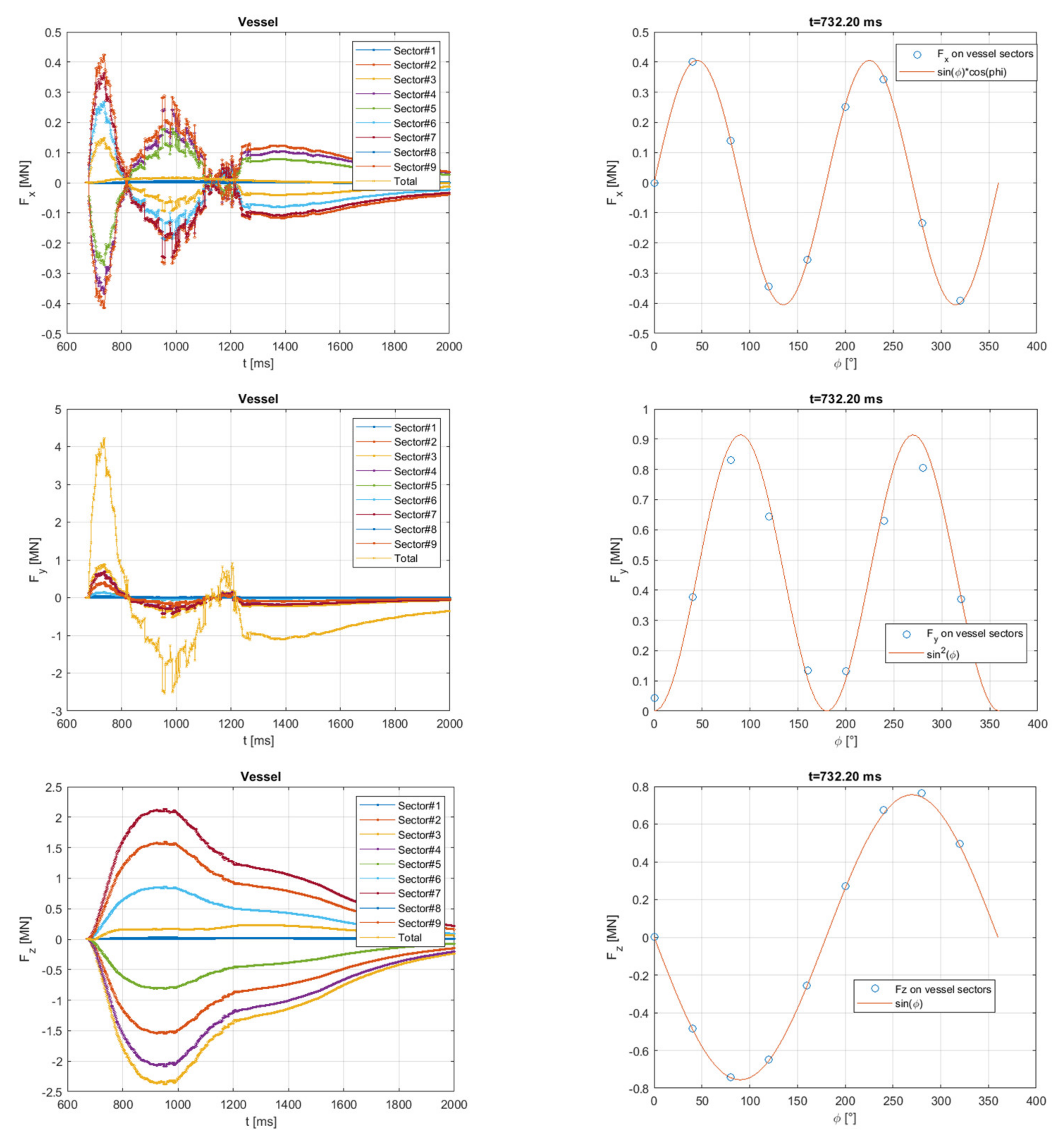
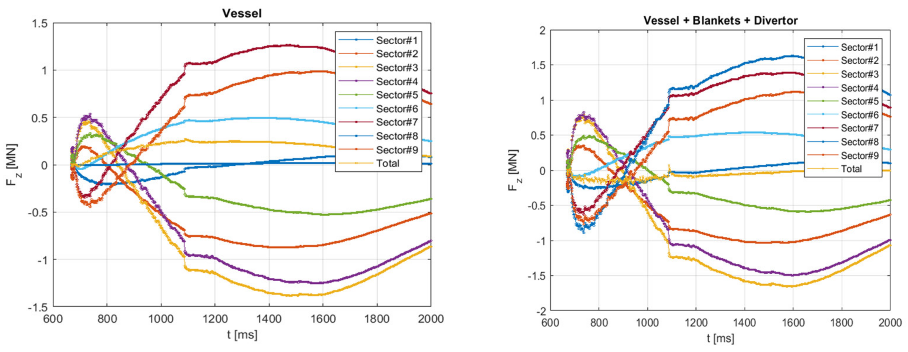
Figure 5 shows numerical results for the Model #1. These results fully respect the symmetry and anti-symmetry of lateral forces analytically derived for this Model above, as seen from properly mirrored waveforms of lateral EM forces (bi-directional
Fx and
Fz, however unidirectional
Fy) applied at nine separate VV sectors.
6. Model #2 of Bridges for the Perfectly Anti-Symmetric Halo Current Component
The main advantage of the first model presented in previous section is that it simulates gradual slipping of the halo current “injection belts” down along the first wall, exactly in the same way as already done in VDE post-processing, e.g., in [
6]. However, as a main disadvantage, it does not reproduce details of magnetic fields caused by asymmetric distortion of helical current in the plasma Halo layer; thus, it does not reflect the interaction of helically distorted magnetic fields with all currents, neither does it reflect helical eddy currents in VV with internals, and, accordingly, misses some components of asymmetric loads applied at VV and the Magnets.
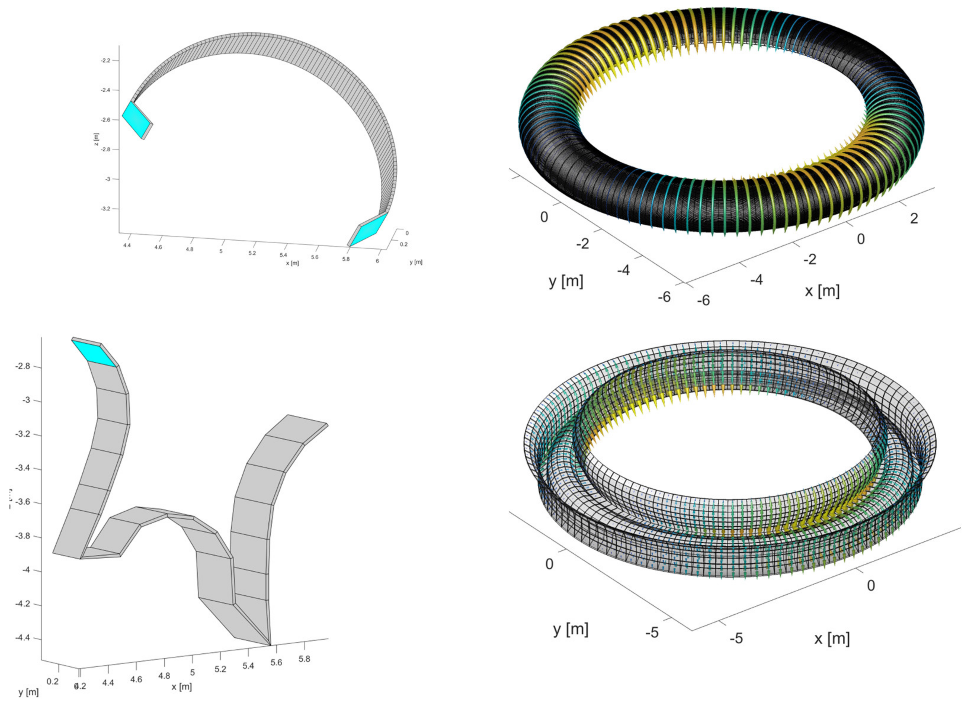
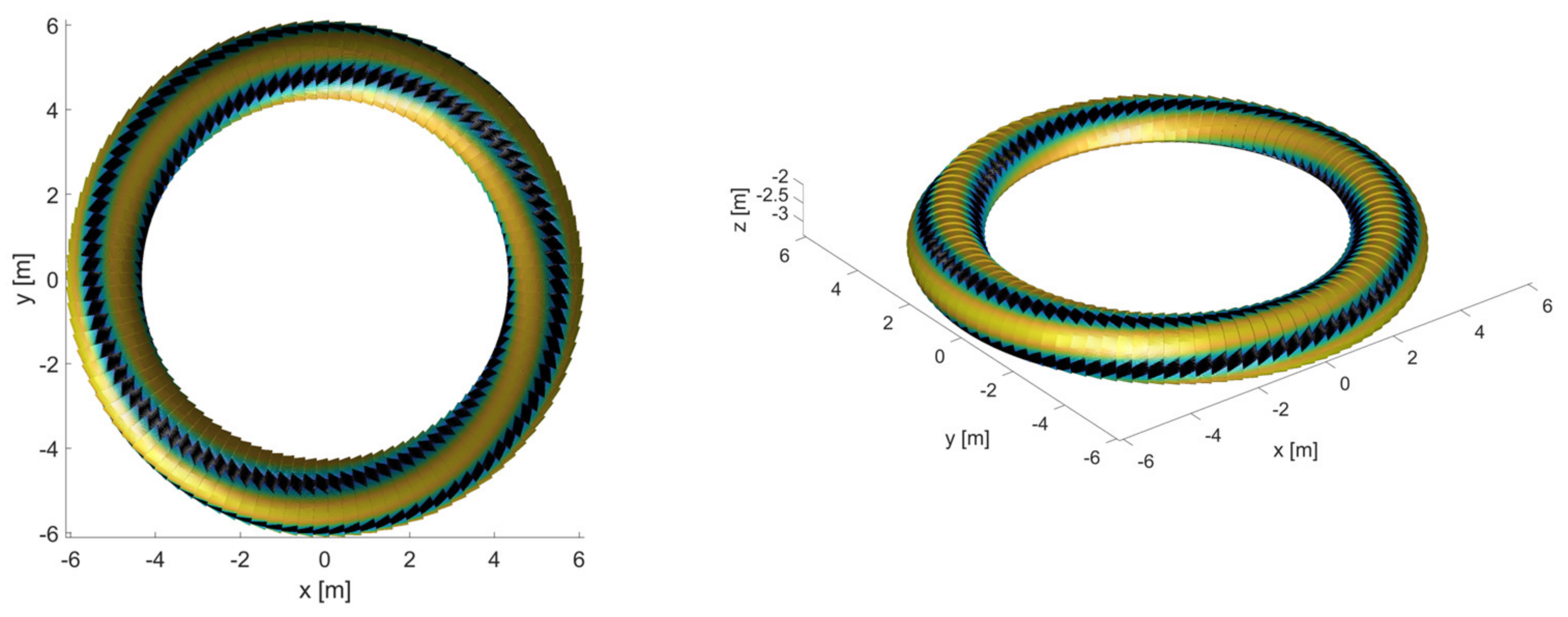
This section describes a new model of helical bridges for the perfectly anti-symmetric halo current component proposed by this article. It is marked as Model #2 and illustrated by
Figure 6 and
Figure 7, with results presented in
Figure 8 and
Figure 9. It uses the same mesh of VV with internals as shown in
Figure 3, but differs from the model#1 by helical (not poloidal) bridges closing the anti-symmetric halo currents around plasma.
Figure 6 shows only these helical bridges, but not the rest of the FE model already presented in
Figure 3. Right now, Model #2 assumes fixed location of the halo current injection belts.
We can say that, in comparison with Model #1, Model #2 has both main features inverted. It represents, as far as possible, the helical pattern of anti-symmetric halo currents in a course of AVDE; however, it still waits for upgrade to the gradually slipping halo current injection belts. We do hope that future AVDE EM models based on this principle will both combine the advantages explained here and avoid drawbacks.
The Model #2 includes 101 identical helical bridges wrapping around the plasma. They are equally spaced in the toroidal direction and fed, at each time instance, by harmonically distributed (around the torus) currents composing always zero total.
Main advantage of Model #2 is that, being superimposed with the symmetric VDE model, it creates a 3D pattern of halo currents resembling the kink mode (built here to match mode
m = 1,
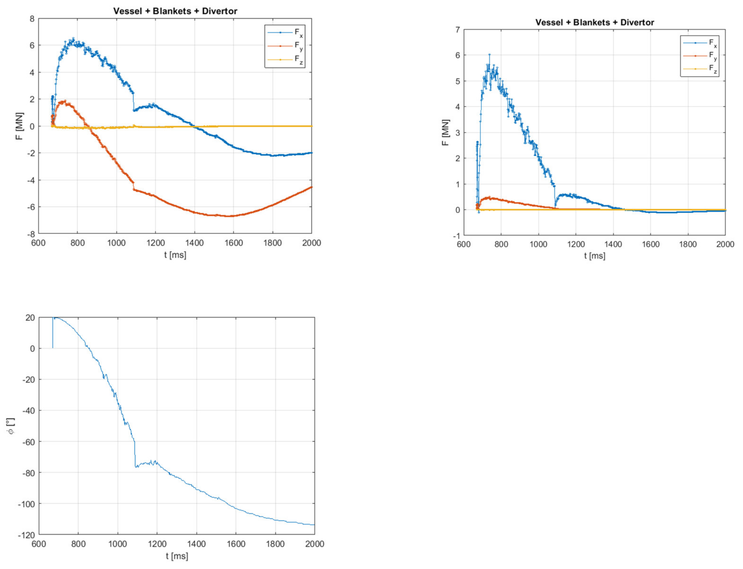
n = 1, may be varied later). Such helical anti-symmetric transient currents in the Halo layer also induce helical anti-symmetric eddy currents in VV with internals. Helical eddy currents in VV at VDE and AVDE exist in real tokamaks, but are not reflected by Model #1. Such helical currents do influence the entire pattern of transient magnetic fields and EM loads. Being induced fast, these currents continue their evolution with their own decay times, thus, seriously impacting time-dependent patterns and waveforms of net EM loads, as can be seen from comparison of relevant plots in
Figure 6 for model #1 and
Figure 9 for model #2. Being closer to the real helical magnetic configuration, Model #2 helps to refine net EM loads balance between VV and the Magnets, to obey zero net loads at plasma, and at the tokamak as a whole, - similarly as reminded by [
7] for VDE. Accordingly, it helps to improve an accuracy of delivered waveforms of lateral EM loads.
There is a plan to use Model #2 for parametric investigation of lateral EM loads caused by rotating AVDE. Further evolution of Model #2 may be from the single set of helical bridges to several enclosed sets, all with different halo current injection belts, fed by anti-symmetric halo currents gradually migrating from the most outer set to the most inner set, similar to what is commonly done in EM models for VDE post-processing. The enclosed helical sets may be built with different helicities to better match evolution of the plasma q-parameter.
The following simple consideration explains different sensitivities of various components of AVDE-induced loads to uncertainties (natural variability) of VDE and AVDE in real tokamaks and in numerical models.
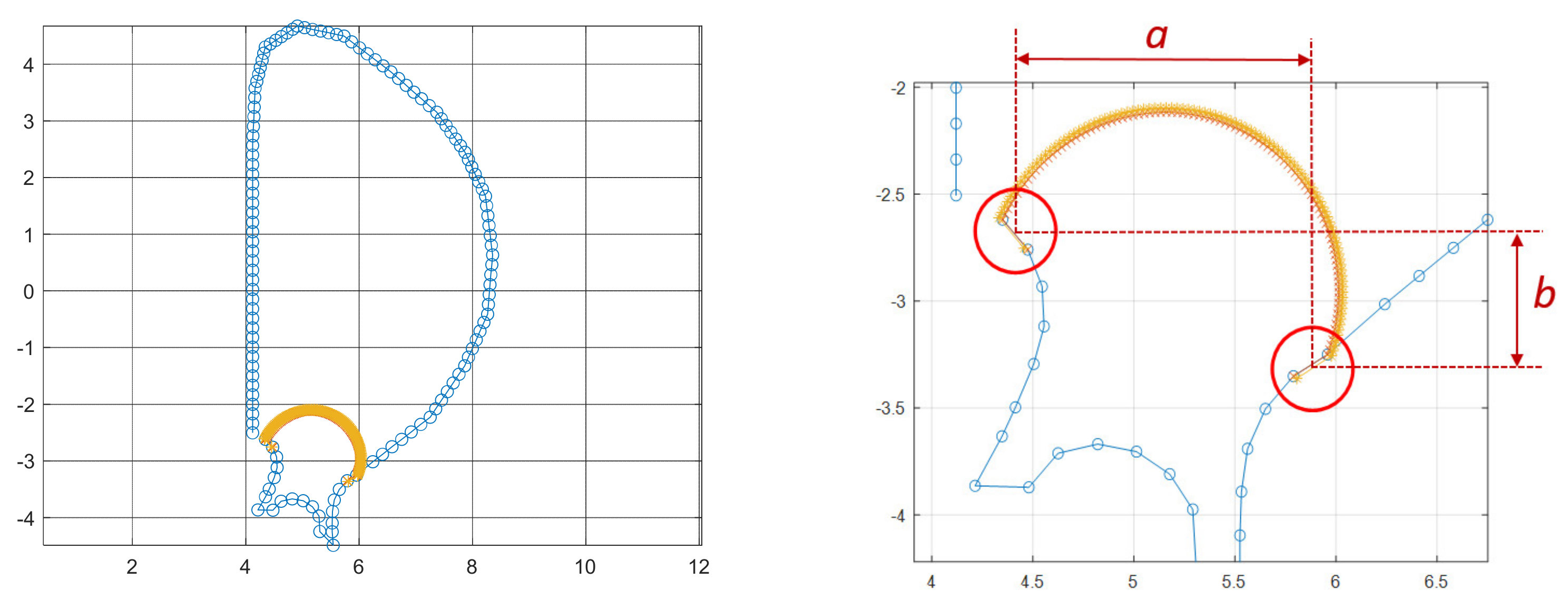
Figure 7 indicates distances “
a” and “
b”: They are radial and vertical current paths between inboard and outboard halo current injection belts. Simplistically, ignoring magnetic field gradients, we can say that:
- -
Radial distance, “a” is responsible for net lateral force in x-direction: Fx ~ Ih,A* < Bp > *a, and also for contribution in the lateral torque around x-axis: Mx ~ Ih,A* < Bt > *a* < r >;
- -
Distance “b” is responsible for only net lateral force in y-direction: Fy ~ Ih,A* < Bp > *b.
Experts who have observed or simulated VDEs know that in real VDE-s, and in the simulated ones, when plasma drifts downward (or upward), it may go along slightly different trajectories: slightly more to inboard, or slightly more to outboard. This depends on specific plasma parameters taking place prior to VDE. These real-life variations rather modestly influence the distance “a”, but have much stronger impact on the distance “b”. Thus, we can say that variations of initial plasma parameters prior to VDE evolving in AVDE in real tokamaks, and in numerical models, have a modest influence on lateral load components Fx and Mx; however, they have much stronger impact on peak lateral force Fy.
This logic contributes to the following practical conclusions: At comparison of outputs from different AVDE models, we shall not be surprised by a large deviation in lateral net force Fy; however, we may anticipate rather good match of orthogonal lateral force Fx and torque Mx. Accordingly, EM analysis reports should concentrate attention on lateral torque (the overturning moment) because it is: (a) the dominant component of lateral AVDE loads (as shown in next sections), and (b) component less sensitive to model assumptions and to variability of AVDE in real life.
In the first two plots of
Figure 9, waveforms of two orthogonal lateral forces
Fx and
Fy are dissimilar and have a phase shift. This means they indicate a rotation of a resultant vector of lateral AVDE-induced net EM force even at the locked AVDE. An explanation may be in the varying in time and decaying on its own pattern of helical eddy currents in VV induced by pulsed currents in helical bridges, combined with also varying asymmetric components of magnetic fields. This effect, the rotation of the net lateral EM force vector, even at the locked AVDE, is worth a deeper exploration in further studies with Model #2.
7. Comparison of Main AVDE Load Components Obtained with Models #1 and #2
Table 1 collects main numerical results obtained with Models #1 and #2. They both are for the assumed here fraction of the anti-symmetric halo current density
f = 0.5. The Table shows peak lateral forces and their ratios to peak vertical force applied at VV as obtained by VDE post-processing. These lateral EM loads come from the interaction of only anti-symmetric currents in all structures with external magnetic fields produced by TF coils, CS, and PF coils and by the plasma, and with the self-field produced by the anti-symmetric halo current pattern. These values, however, already can serve as ready-for-use lateral components of AVDE-induced EM loads, since the symmetric component of halo current, and resultant eddy currents, do not create net lateral EM loads.
In a practical sense, in terms of loads needed for structural analysis of VV and the Magnets supports, the largest contributor in AVDE-induced net EM loads at VV and the Magnets are not lateral net forces but the overturning moments, also called lateral torques. They result mostly from a pair of opposite vertical forces applied at two halves of the torus due to the interaction of anti-symmetric poloidal halo currents in VV with a toroidal magnetic field. Plots of bi-directional vertical forces at nine VV sectors (
Figure 5 for Model#1 and
Figure 8 for Model#2) allow estimations of the main contributor in the lateral torque. For the Model #1, lateral torque created in VV itself is found numerically as M
x ≈ 80 MN*m. However, total lateral torque for VV with blanket and divertor (also for Model #1) peaks at M
x ≈ 115 MN*m. For Model #2, total lateral torque for VV with internals is smaller, just ≈ 70 MN*m. Main factors causing such differences were investigated with two supplementary models as described in next section.
By considering these rather high values of torques, we may conclude that all EM studies on AVDE-induced lateral loads shall pay attention not only to net lateral forces, but also to net lateral torques (the overturning moments).
All models described here permit almost-linear scaling of all lateral EM loads, proportionally to the assumed fraction of the anti-symmetric halo current density “
f”. While
Table 1 shows results for modest AVDE assuming
f = 0.5,
Table 2 shows all doubled results corresponding to more severe AVDE featuring
f = 1.0. This article does not discuss realistic limits for AVDE severity, leaving this choice to the tokamak physics community, which summarizes and investigates outcomes of AVDE in real tokamaks and corresponding numerical simulations.
The evident difference in x-directed lateral forces between Models # 1 and #2 may be explained by two factors:
- -
By helical eddy currents in VV simulated by Model #2, but omitted by Model #1;
- -
Because Model #1 restricts halo currents in VV to purely poloidal direction, while Model #2 avoids such restriction. We think this helps to better match real helical current patterns everywhere, thus, delivering more realistic outcomes.
We can say that the two presented models deliver the vector sum of peak lateral net forces ranging from 7% to 11% of Fz found at VDE for f = 0.5 and, accordingly, from 14% to 22% of Fz found at VDE for f = 1.0.
Before investigation of specific reasons for discrepancy between Models #1 and #2 attempted in the next section, we can simply average the results for Models #1 and #2; thus, we say that lateral torques evaluated here with Models #1 and #2 are 95 MN*m (+/−20%) for f = 0.5, or 190 MN*m (+/−20%) for f = 1.0.
To save computational resources in a course of simulation of EM transients caused by only the anti-symmetric halo component, it is worth to remove all coils (“the Magnets”) from the EM model with the perfectly anti-symmetrical halo currents. It is possible because the perfectly anti-symmetric halo current component is magnetically de-coupled from all major coils (toroidal and poloidal). Thus, FE simulation without the Magnets already delivers full values of net lateral loads. However, the Magnets are to be “returned back” in the model prior to calculation of the distributed anti-symmetric EM loads, since otherwise net vertical forces and pulsed EM loads at separate coils will be lost, and overall pattern of 3D EM loads everywhere distorted.
We shall highlight that the results presented here are not for the worst foreseen VDE and AVDE, but for a typical VDE which continues as a kind of “medium scale” AVDE. By this reason, the results shown here cannot be used directly for purposes of load specifications. Recommendations for load specifications may appear later, when the tokamak physics community will select and specify, in terms described above, input parameters corresponding to the worst realistically possible AVDE scenarios.
8. Two Supplementary Models of the Bridges for the Anti-Symmetric Halo Current Component Aimed to Quantify Effects of the Simplifying Assumptions
The following two supplementary models, marked as Models #3 and #4, have been developed with a purpose to find and compare errors caused by the separate simplifying assumptions described above. They both use the same mesh of VV with internals as presented in
Figure 3, and vary only by the shape of bridges built to close the halo currents loop. These bridges (but not full FE models) are shown in
Figure 10. Both Models #3 and #4 assume purely poloidal current density in the bridges and fixed locations of halo current injection belts. In Model #3 (upper row in
Figure 10), the bridges wrap around the plasma. In Model #4 (bottom row in
Figure 10), the bridges are located close to the first wall.
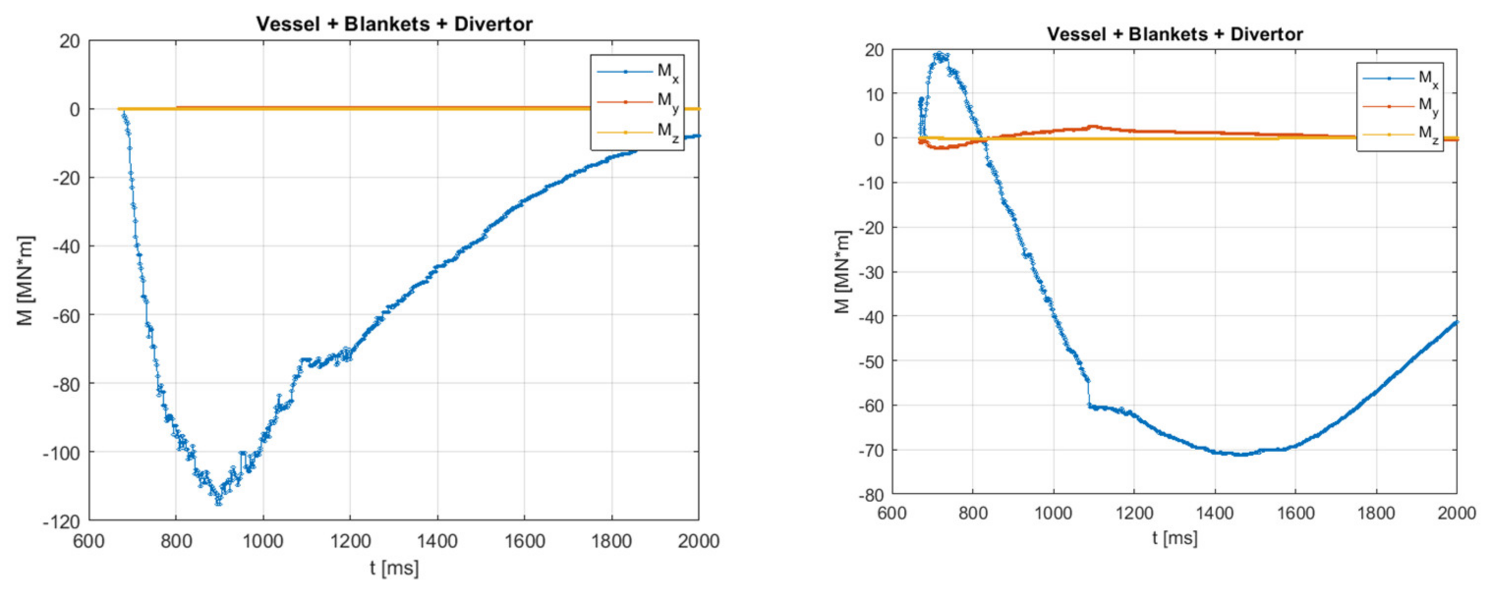
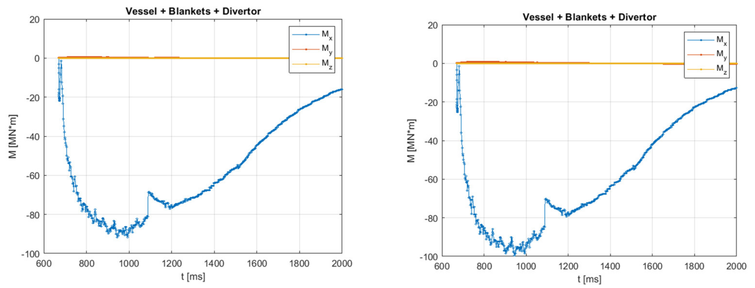
Figure 11 compares outcomes of all 4 models (upper row is for Models # 1 and 2, bottom row is for Models # 3 and 4) in terms of dominant asymmetric load components: overturning moments applied at the Vacuum Vessel with blanket and divertor due to interaction of asymmetric eddy currents with the toroidal magnetic field. Of course, by conservation law, the same by modulus but opposite by direction overturning moments apply to the Magnets.
Figure 11 shows the total spread of the overturning moments in the range from 70 MN*m to 115 MN*m. Keeping in mind all simplifying model assumptions and also unique plasma behavior in each next AVDE, this spread looks modest and, in principle, permits to use any of these models. However, below we compare these models in pairs to see errors caused by specific simplifying assumptions, with a purpose to decide on the single practical model for parametric studies.
The only difference between Models #1 and #4 is in either the sliding or fixed halo current injection belts. This pair delivers peak overturning moments ~115 MN*m and ~100 MN*m. We see that, in our specific case, Model #4 having the fixed belts leads to an underestimation of ~15%. We may conclude that it is better to not ignore, but simulate, the sliding of halo current injection belts.
The only difference between Models #2 and #3 is in either helical or just poloidal direction of anti-symmetric halo currents wrapping around the plasma. This pair delivers peak overturning moments ~70 MN*m and ~90 MN*m. We see that Model #3, which restricts the anti-symmetric halo currents in plasma to only poloidal direction, leads to an overestimation of ~25%. This gives an advantage to Model #2 attempting to reflect the actual helical pattern of anti-symmetric halo currents wrapping the plasma.
This advantage also relates to the fact that, using a more realistic helical pattern in the bridges, the resulting plasma current density gives a better approximation to the constraint dictated by the MHD equilibrium in the plasma region, defining in principle zero net EM loads at the plasma as a whole. This constraint was kept in mind, as a goal, at the described above shaping of the anti-symmetric halo current component in Model#2, however not explicitly enforced in this engineering-oriented model. Similar consideration provided in [
9]. This explains why all EM post-processing codes show some residual (non-physical) net EM loads at plasma as a whole and at the tokamak as a whole, when by conservation laws these shall be practically zero. Consequently, such model non-idealities disturb net EM load balance between VV and the Magnets, that is better to avoid in inputs for dynamic simulations. A way to better balance net EM loads between VV and the Magnets explained in [
7] and implemented in practice at simulation of tokamak dynamic response to pulsed EM loads at development of ITER tokamak monitoring algorithms.
Furthermore, by comparing outcomes of Models #2 and #3, we may think that a definitively not-perfect match between time-dependent helicity of halo layer at AVDE in real tokamak, and helicity selected and frozen in Model #2, will still cause a tolerable error, in a scale of 25%.
9. Further Work Planned
Further work is to perform more detailed comparison of all EM models described here and perhaps their hybrids, and to conclude with a selection of a single practical model. Quite likely, we will prefer a hybrid which combines advantages and avoids drawbacks of Models #1 and #2.
Then, extensive parametric studies will continue with just one practical model. They will fill a library of AVDE-induced lateral EM loads (time-dependent patterns and waveforms of net lateral forces and torques) for a wide spectrum of AVDE scenarios. This AVDE library will span from a mild to a medium and to the heaviest AVDE scenarios. The tokamak physics community may suggest a few, presumably the heaviest but still realistic, AVDE scenarios as outcomes of various real tokamak experiments and plasma-physical simulations performed by several teams at varied assumptions with different plasma simulators. Then, the AVDE library will offer to the engineers ready-for-use waveforms on net lateral AVDE loads and detailed time-dependent patterns of asymmetric EM force densities in all structures for the indicated AVDE scenarios.
The parametric study, presumably, will use the following input variables:
- -
Fraction of the anti-symmetric halo current density f = 0.25, 0.5, 1.0;
- -
Various grow rates of the ratio indicated above, including the simplest constant ratios used here;
- -
Will compare the locked and the rotating AVDE, with varied rotation speed;
- -
With varied helicity of the enclosed helical bridges (which involves work on model upgrade).
Main outcomes will be waveforms and peaks of:
- -
Lateral forces at VV with internals, and opposite at the Magnets;
- -
Ratio of peak lateral forces to peak vertical force applied at VV with all internals;
- -
Lateral torques at VV with internal and opposite at the Magnets;
- -
Ratio of peak lateral torques to peak vertical force at relevant VDE (dimensioned in meters).
10. Discussion and Conclusions
The new principle of simple parametric AVDE models composed by symmetric and perfectly anti-symmetric halo current components described here opens a possibility to create a library of ready-for-use waveforms of lateral AVDE-induced EM loads (forces and torques) and time-dependent patterns of EM force density for a wide range of parametrically varied input assumptions describing possible variants of AVDE evolution.
These AVDE models may suit purposes of load specification only at the following strict condition: They shall offer AVDE loads only as a function of input assumptions on the severity of AVDE. Such an input assumption is to be specified by the physics community, e.g., in terms of the largest anticipated fraction of anti-symmetric halo current density “f”, its profile (simple harmonic or more peaked), variation of this factor in time, specific halo layer helicity, its variation in time, etc.
The reported here quantitative results show that, at for an arbitrarily picked medium (by far not the worst) input assumption on a ratio of anti-symmetric to symmetric halo current density (
f = 0.5), presently supposed as a constant in time, with presently built AVDE EM models, the modulus of peak lateral force ranges from 7% to 11% of peak vertical force calculated at VDE. Assuming a more severe AVDE featuring a higher asymmetry
f = 1.0, this ratio is from 14% to 22%. These results fit well under the ratio presently recommended for ITER (e.g., [
9]), where modulus of lateral AVDE-induced force is approximately a half of modulus of vertical force at either VV or the Magnets. We do not suggest the relaxation AVDE loads recommended for ITER, since the models described here will still evolve and converge, and because the worst (for loads) variant of AVDE evolution is still to be selected by the physics community. It is also worth noting that all results presented here are not for the heaviest but for “mild” VDE and AVDE scenarios, since they served the development of Tokamak Monitoring algorithms, not the load specifications.
The most important (for purposes of structural analysis) component of AVDE-induced EM loads is not lateral net force but lateral net torque (the overturning moment, Mx). At identical inputs, all four models compared here delivered Mx in the range from 70 MN*m to 115 MN*m at f = 0.5, or from 140 MN*m to 230 MN*m at f = 1.0. We did not compare these torques with outcomes of other AVDE studies, since we are not aware of articles reporting AVDE-induced lateral torques for ITER-scale tokamaks. We just would highlight, that any AVDE studies, with any AVDE models, shall deliver not only lateral net EM forces, but also lateral net EM torques. The four models compared here show similar peaks of net lateral EM loads (forces and torques); however, their waveforms delivered by Model #2 seriously differ from the outcomes of all others. Realistic waveforms are important for consequent dynamic simulations (not reported here), as needed for the development of Tokamak Systems Monitoring algorithms and tokamak simulators.
Only Model #2, newly introduced by this article, shows significant rotation of net lateral force vector even at the locked AVDE. We may connect this effect with the fact that only this model realizes a new feature: not poloidal but helical bridges wrapping around the plasma and attempting to match the helicity of the halo current.
A plan is to upgrade Model #2 toward gradually slipping halo current injection belts and employ it then as the single practical model for extensive parametric calculations. We think that such convergence will deliver not only as accurate as practically possible peaks of lateral EM forces and torques, but also as possible realistic time-dependent patterns of EM force densities, modulus, and vector directions of net loads and especially their waveforms, for use in consequent dynamic simulations.
We keep in mind that the practical purpose of the AVDE EM models introduced here is just to fill a library of ready-for-use lateral EM loads for many variants of plasma-physical assumptions on the evolution and severity of AVDE, and then the tokamak physics community may indicate most-likely or worst-possible variants in this library.


