Article

Changes in Morphology Caused by Mass Transfer Phenomenon

by
Toshihiro Ishikawa
Department of Pharmaceutical Engineering, Tokyo University of Science, Yamaguchi, 1-1-1 Daigaku-Dori, Sanyo-Onoda 756-0884, Yamaguchi, Japan
Ceramics 2025, 8(4), 120; https://doi.org/10.3390/ceramics8040120
Submission received: 27 August 2025 / Revised: 20 September 2025 / Accepted: 22 September 2025 / Published: 24 September 2025
(This article belongs to the Special Issue Advances in Ceramics, 3rd Edition)

Abstract

The mass transfer phenomenon of contained impurities causes differences in the morphologies, densification processes, and heat resistance of ceramics. Of these, in this paper, differences in the heat resistance of ceramic fibers are discussed. Third-generation SiC polycrystalline fibers demonstrated excellent heat resistance. However, at temperatures above 1800 °C, sintered fiber (Tyranno SA) and non-sintered fiber (Hi-Nicalon Type S) showed remarkable differences in heat resistance. At temperatures above 1800 °C, the non-sintered fiber underwent structural changes, including the formation of a surface carbon layer and abnormal SiC grain growth, whereas the sintered fiber maintained its stable polycrystalline structure. Until now, these differences and a detailed description of them have not been discussed. Here, we first explain the dramatic differences in heat resistance that occurred at high temperatures in relation to the mass transfer of excess carbon. Our findings should be widely used for the development of much more stable structures and for the long-term use of materials at higher temperatures in applications such as airplane engines and turbines.

1. Introduction

The characteristics of functional materials may be dominated by a small amount of impurities in their intermediate materials [1,2,3,4,5,6,7,8,9,10]. To date, numerous Si-containing ceramics with characteristics dominated by impurities in their precursor materials have been developed [11,12,13,14,15]. Figure 1 depicts some characteristics of Si-contained ceramics dominated by impurities. The transformation of impurities can induce changes in the obtained morphology and triggers of the solid sintering process, and differences in the heat resistance of SiC polycrystalline fibers can also be caused by the transformation of impurities. SiC polycrystalline fibers are the most heat-resistant polymer-derived SiC fibers. Since the first precursor ceramics, which were developed using polycarbosilane [16], many polymer-derived SiC fibers have been developed [12,17]. Through these developments, the heat resistance of SiC-based fibers have remarkably increased from 1300 °C to 2000 °C. Of these fibers, SiC-polycrystalline fibers (Tyranno SA and Hi-Nicalon Type S) show the highest heat resistance of up to 2000 °C, and have been actively evaluated for aerospace applications in the form of SiC matrix composites. The ultimate aim of aerospace engine manufacturers is the development of uncooled engines. A critical parameter for the high thermal efficiency of gas turbine aeroengines is a high overall pressure ratio, which in turn drives high turbine flow path temperatures. The turbine inlet flow path temperatures are generally higher than the thermal limits of metal-based component materials. Therefore, air from the compressor cools the components via a combination of internal and external flow path cooling. However, minimizing the required cooling flow increases the overall efficiency of the cycle, hence the need for developing advanced material technologies with improved high-temperature capabilities, such as ceramic matrix composites (CMCs) using SiC fibers. Overall, the introduction of CMCs enables reductions in fuel burning by up to two percent. Few other technologies in today’s pipelines have this high a capability for fuel burning reduction. Additionally, the material density of CMCs is one-third that of today’s nickel-based alloys, enabling over 50 percent reduction in the turbine component weight. Accordingly, CMC development using SiC fibers is very important. Aeroengine manufacturers are developing new technologies, aiming for new types of aircraft engines that have CMC parts throughout the engine’s hot section. SiC fibers play an important role in CMCs as reinforcement, and can be used at very high temperatures of up to 2000 °C. However, recently, we found remarkable differences in the heat resistance of sintered fiber (Tyranno SA) and non-sintered fiber (Hi-Nicalon Type S) at temperatures above 1800 °C. At temperatures above 1800 °C, the non-sintered fiber underwent structural changes, including the formation of a surface carbon layer and abnormal SiC grain growth, whereas the sintered fiber maintained its stable polycrystalline structure. Here, we explained the dramatic differences in heat resistance that occurred at high temperatures in relation to mass transfer of excess carbon, because up to until now, these differences and detailed descriptions of them have not been discussed. If SiC fibers could achieve long-term use at temperatures up to 2000 °C, the development of future uncooled engines would make significant progress. As mentioned above, remarkable differences in the heat resistance of SiC polycrystalline fibers have been observed. In this study, we addressed the differences in heat resistance among SiC polycrystalline fibers, aiming for the development of excellent heat-resistant SiC polycrystalline fibers.

2. Materials and Methods

In this study, we used two types of SiC polycrystalline fibers (Hi-Nicalon Type S and Tyranno SA). Tyranno SA was produced by heat-treating amorphous Si-Al-C-O fiber synthesized from polyaluminocarbosilane [11]. Polyaluminocarbosilane was prepared via the reaction of polycarbosilane (-SiH(CH3)-CH2-)n with aluminum(III)acetylacetonate. The reaction of polycarbosilane with aluminum(III)acetylacetonate proceeded at 300 °C in a nitrogen atmosphere through the condensation reaction of Si-H bonds in polycarbosilane and the ligands of aluminum(III)acetylacetonate accompanied by the evolution of acetylacetone, and then the molecular weight increased through a cross-linking reaction with the formation of a Si-Al-Si bond. Polyaluminocarbosilane was melt-spun at about 200 °C, and then the spun fiber was cured in air at 160 °C. The cured fiber was continuously fired in inert gas up to 1300 °C to obtain an amorphous Si-Al-C-O fiber (an intermediate fiber). This fiber contained non-stoichiometric excess carbon and oxygen at about 12 wt.%. The Si-Al-C-O fiber was converted into the SA fiber by way of decomposition accompanied by the release of CO gas at temperatures from 1500 °C to 1700 °C and sintering at temperatures over 1800 °C. In this sintering process, aluminum plays a very important role as a sintering aid. This production process is shown in Figure 2. Tyranno SA is commercialized by UBE Industries Ltd. (Ube, Japan).
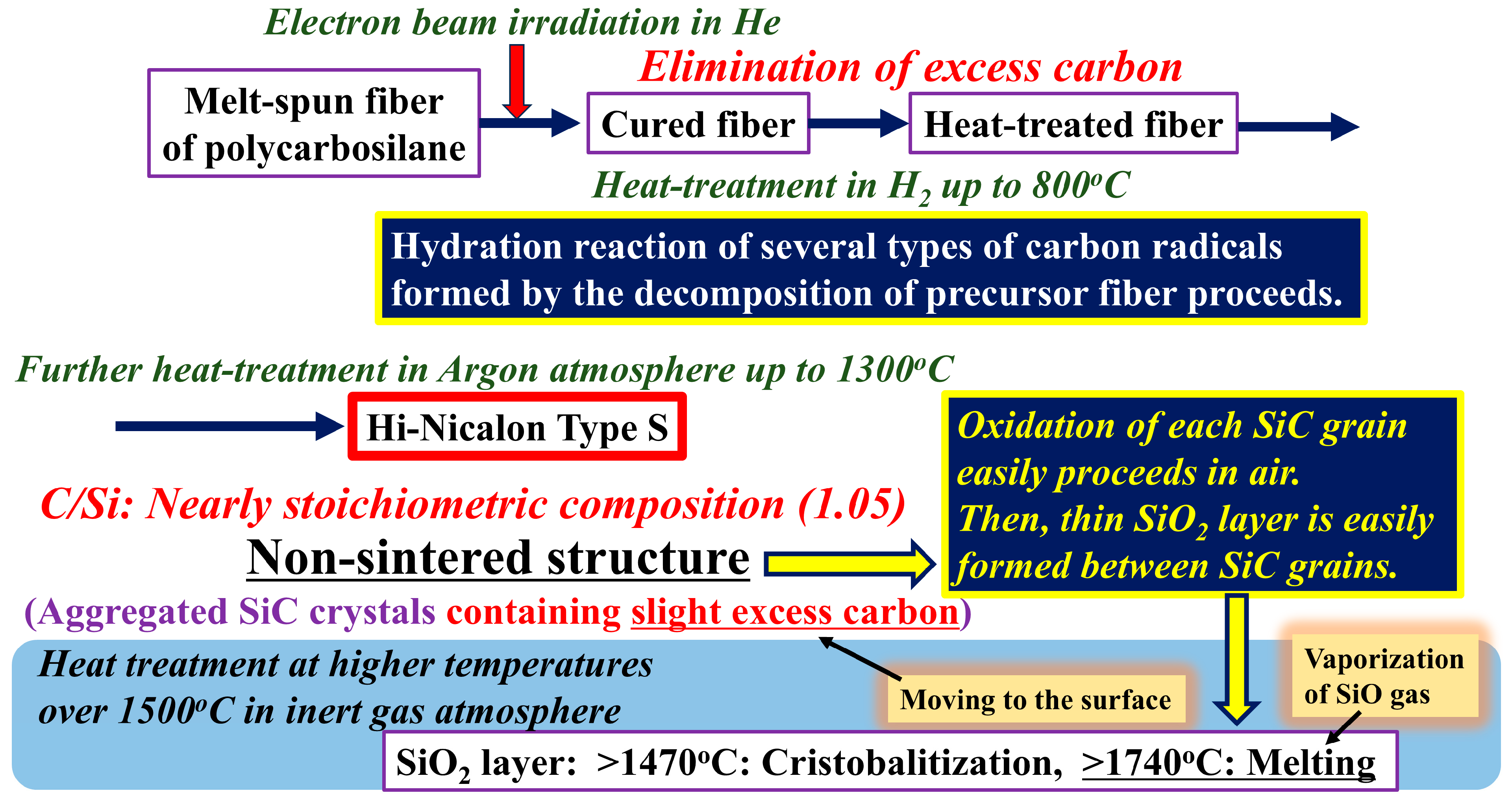
Hi Nicalon Type S was synthesized using melt spinning, electron beam irradiation in He, heat treatment at 800 °C in hydrogen atmosphere (to eliminate excess carbon), and further heat treatment in an argon atmosphere at higher temperatures [17]. Intermediate fibers with various C/Si compositions were prepared by pyrolysis of electron beam-cured polycarbosilane (PCS) fibers in a hydrogen gas atmosphere. The cured PCS fibers were pyrolyzed under H2 gas flow from room temperature to TH (the treatment temperature in H2 gas) and under Ar gas flow at temperatures from TH to 1300 °C with a heating rate of 10 °C/min. The C/Si atomic ratio of the fibers ranged from 0.84 to 1.56. A higher TH yielded a lower C/Si ratio, but at TH ≥ 950 °C, the C/Si ratio was constant, at 0.83. The C/Si ratio dramatically changed at approximately 800 °C. Stoichiometric SiC fiber (Hi Nicalon Type S) could be obtained at TH of slightly higher than 800 °C. The production process of Hi Nicalon Type S is shown in Figure 3.
The microstructure of the heat-treated materials was observed using a field emission scanning electron microscope (FE-SEM), model JSM-700F (JEOL, Ltd., Tokyo, Japan), and a transmission electron microscope (TEM) in conjunction with energy-dispersive spectroscopy (EDS), model JEM-2100F (JEOL, Ltd.).
Heat treatment of the SiC polycrystalline fibers was performed at high temperatures (1600~1900 °C) for 10 h in an argon atmosphere using a Super High Temperature Heating Furnace (model: Pascal 40 made by Nagano, Ltd., Tokyo, Japan).
Oxygen contents of Tyranno SA and Hi Nicalon Type S were measured using an Oxygen Content Analyzer (model: ON736 made by LECO Japan, Tokyo, Japan).

3. Results and Discussion

3.1. Differences in the Fine Structure and Oxygen Content of Polycristalline Fibers

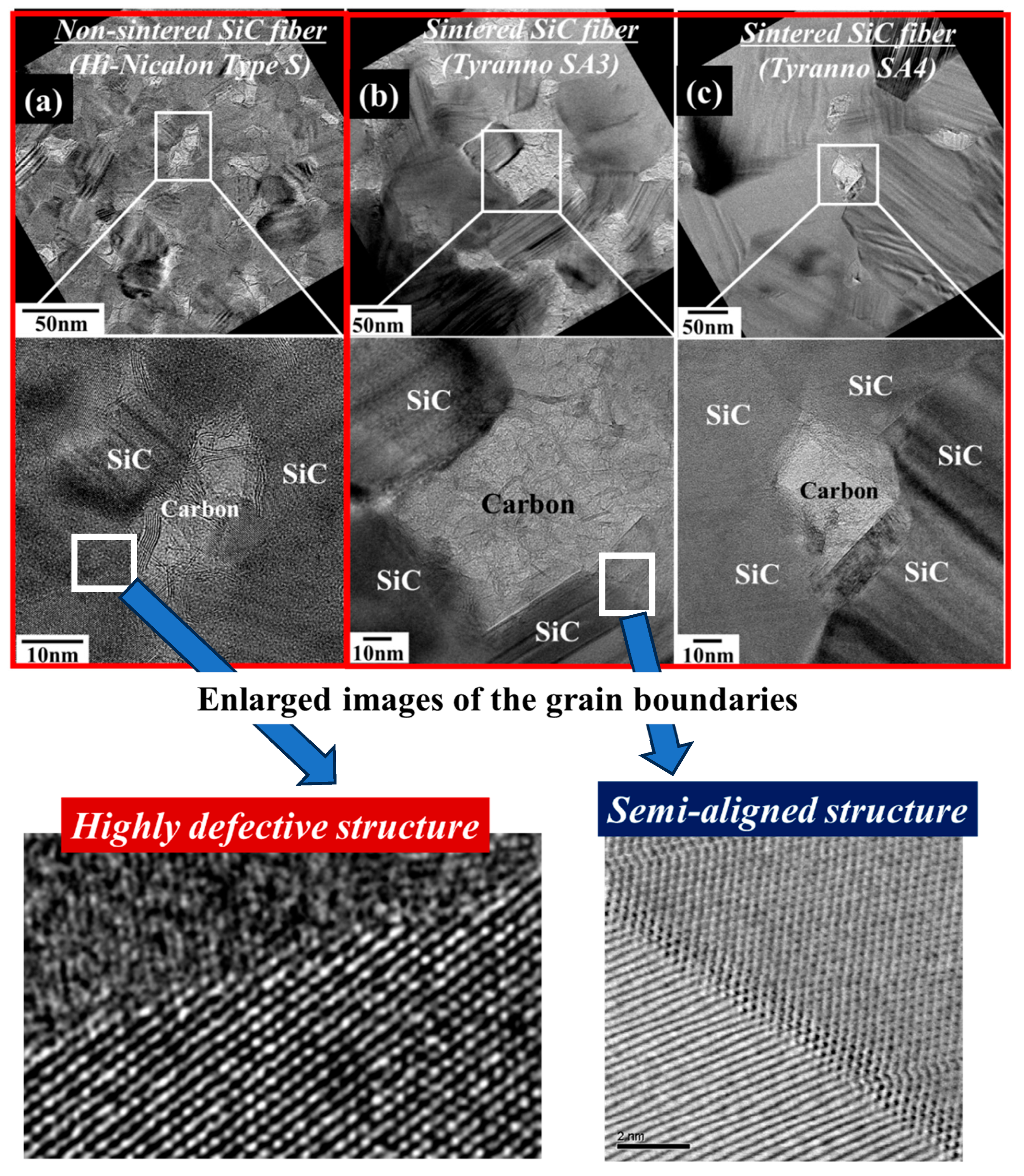
Figure 4 shows the TEM images of the internal structures of the SiC polycrystalline fibers. The images show dense structures containing excess carbon in the fibers. However, these fibers are classified into two categories: sintered fibers (Tyranno SA3 (b) and Tyranno SA4 (c)) and non-sintered fibers (Hi-Nicalon Type S (a)). The grain boundaries of the sintered fibers exhibited dense structures composed of semi-aligned structures. In contrast, the grain boundaries of the non-sintered fiber are generally highly defective [18]. Although numerous SiC-based fiber types have been developed thus far with the aim of creating heat-resistant materials, the characteristics of these fibers differ from one another [19,20,21]. To clarify the differences in the heat resistance of SiC polycrystalline fibers, this study addresses the relationship between the abovementioned structural differences and their characteristics.
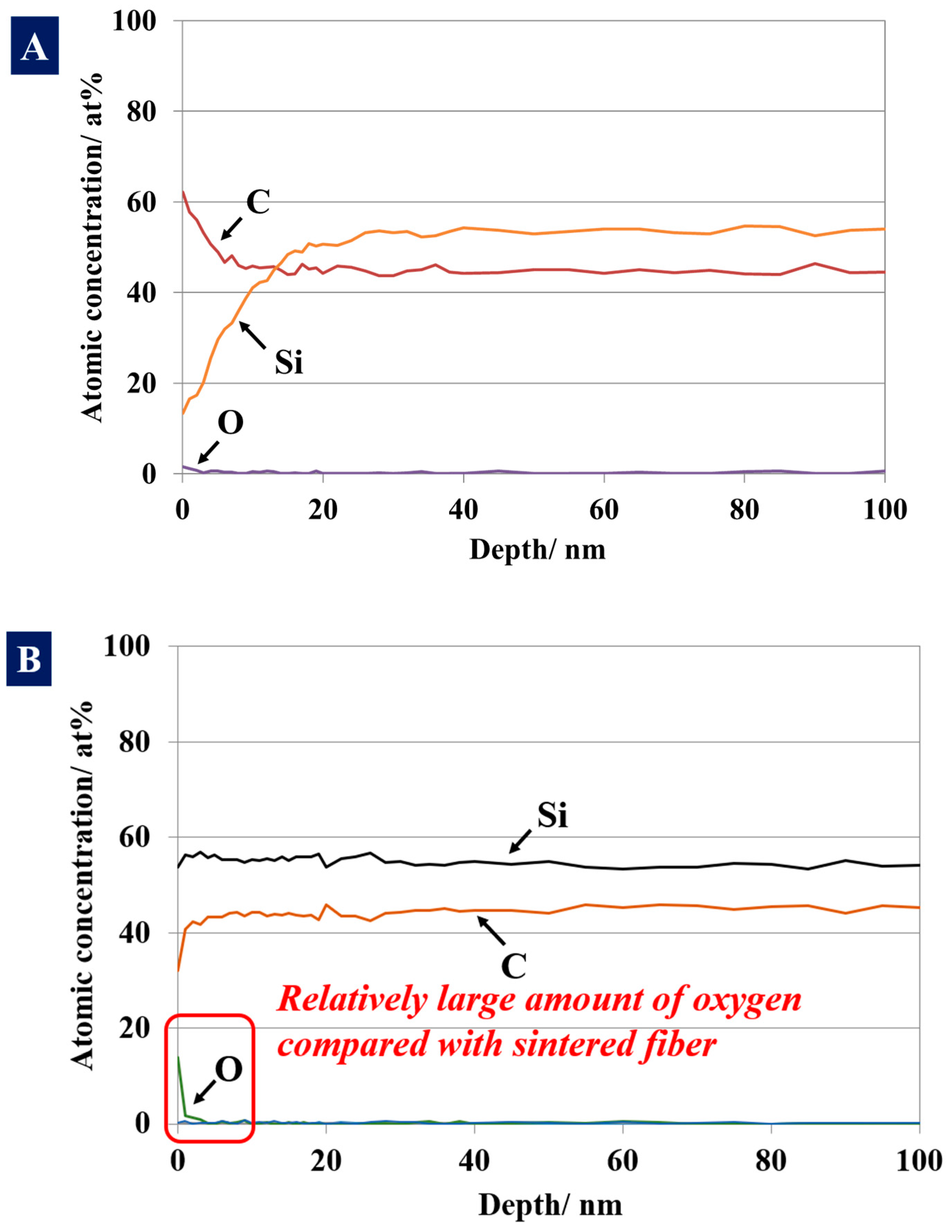
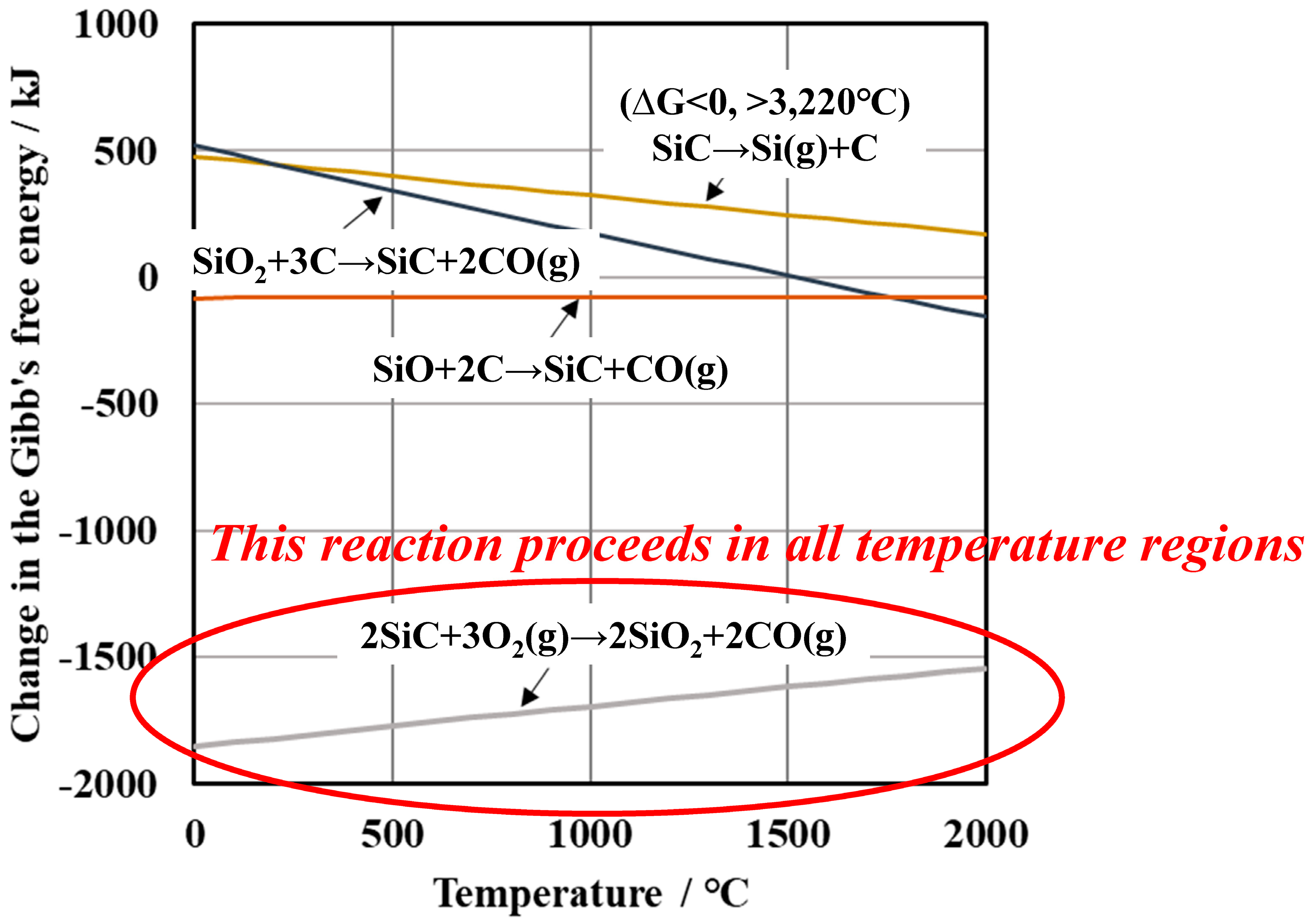
The oxygen content of the sintered fiber (Tyranno SA3: 0.02 wt.%) and the non-sintered fiber (Hi Nicalon Type S: 0.57 wt.%) differed. The surface regions of these fibers contain relatively higher amounts of oxygen than the inside (Figure 5A,B). This is because SiC crystal is readily oxidized in air, even at room temperature, as evidenced by the changes in the Gibbs free energy (Figure 6) of the following reaction.
2SiC + 3O2(g) → 2SiO2 + 2CO(g) (ΔG < 0 at all temperature ranges)
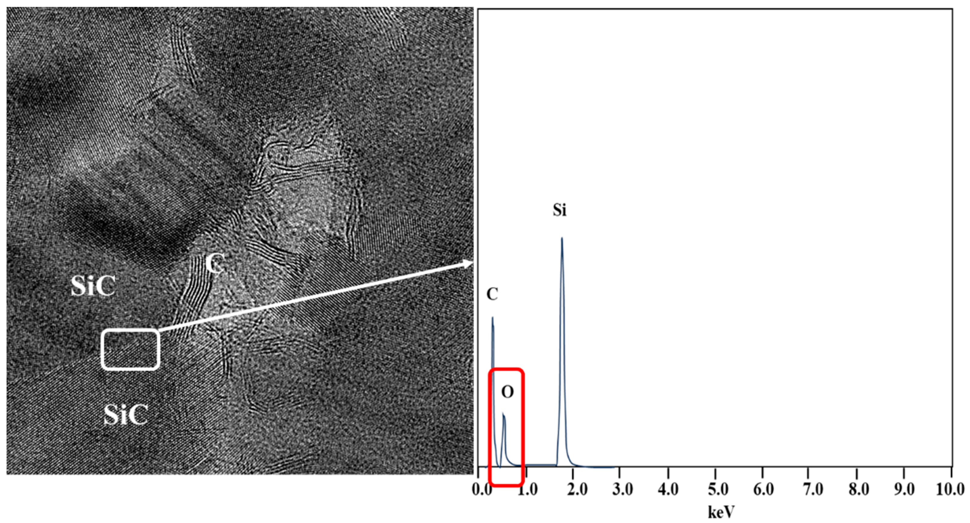
As mentioned above, the surface region of the non-sintered fiber (Hi Nicalon Type S) (Figure 5B) contained more oxygen than that of the sintered fiber (Tyranno SA3) (Figure 5A). In a selected area of the surface region of the non-sintered fiber (Hi Nicalon Type S), an oxygen-rich layer was observed at the SiC crystalline grain boundary. In Figure 7, the result of EDS at the grain boundary of Hi-Nicalon Type S is shown. These differences between the sintered and non-sintered fibers were thought to be caused by differences in the production process, that is, the presence or absence of a sintering process. As mentioned previously, the grain boundary of the non-sintered fiber was defective compared to that of the sintered fiber. Accordingly, oxygen diffusion in the grain boundary region of the non-sintered fiber is thought to have occurred easily.

3.2. Differences in the Heat Resistance of These Fibers

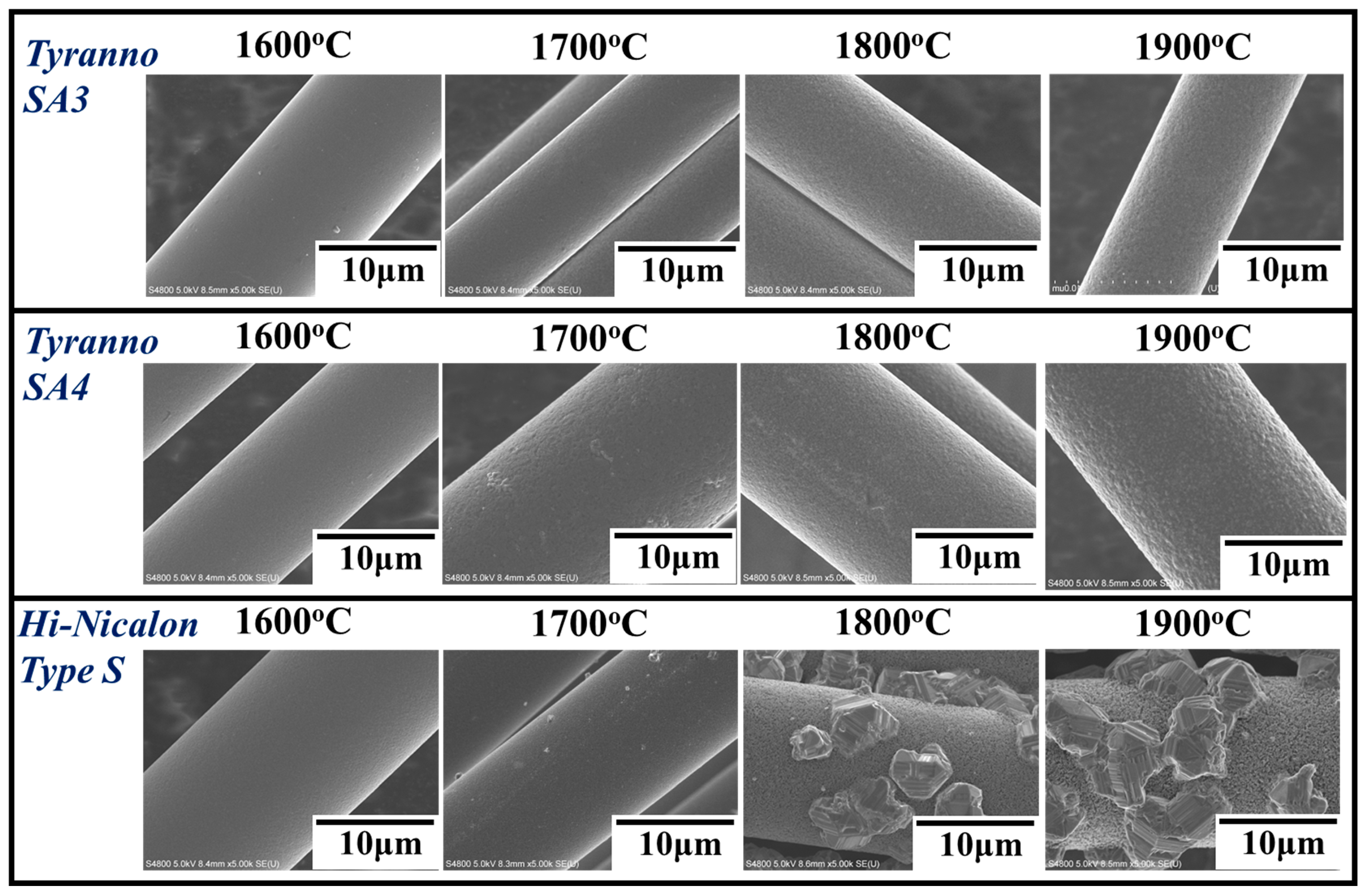
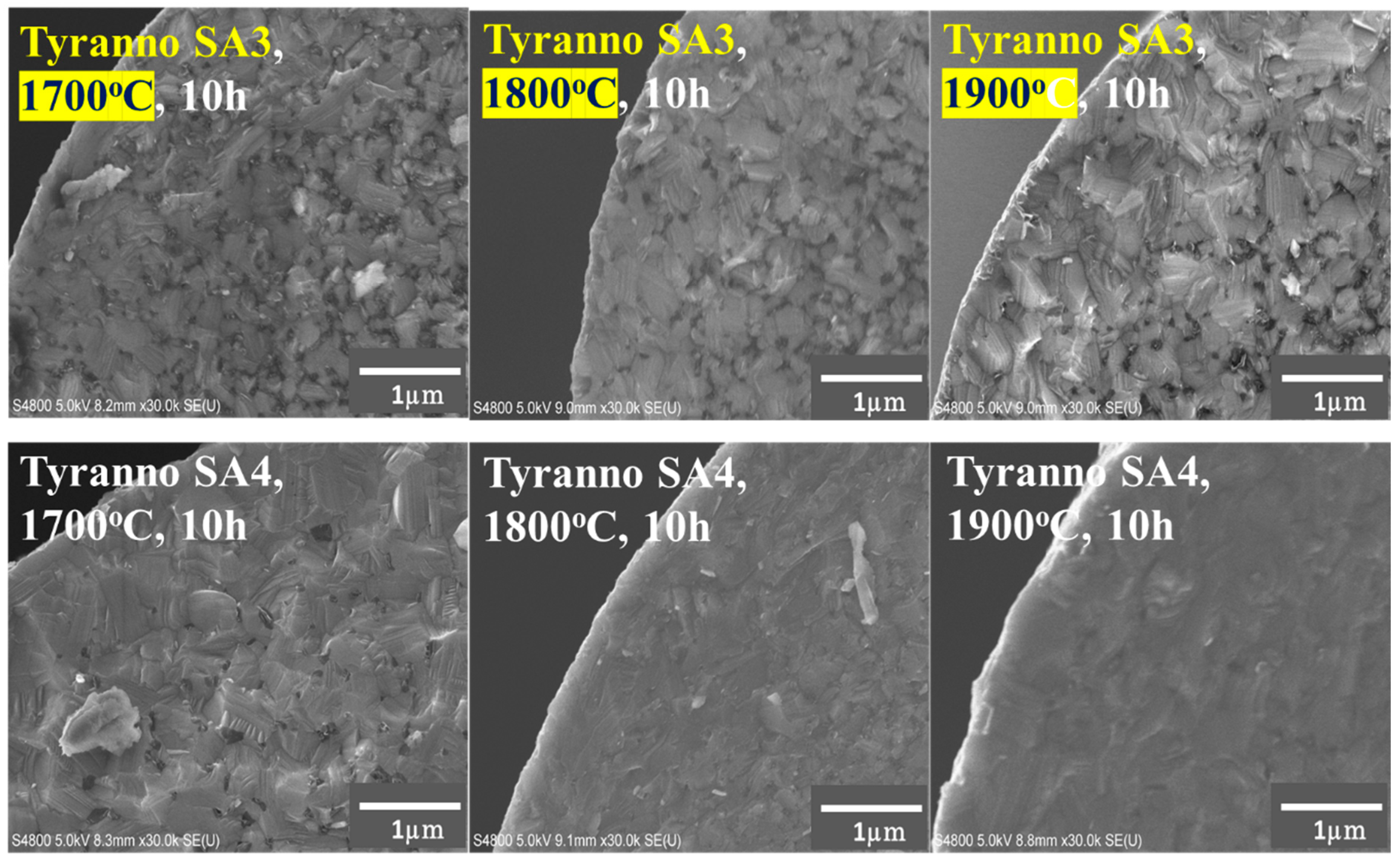
Figure 8 shows the SEM images of the specimen surfaces after heat treatment at high temperatures (1600~1900 °C) for 10 h in an argon atmosphere. The figure illustrates that, at temperatures above 1800 °C, particle formations were observed on the surface of the non-sintered fiber (Hi-Nicalon Type S), while no changes were observed in the surfaces of the sintered fiber (Tyranno SA3 and Tyranno SA4). Furthermore, the heat treatment at temperatures above 1800 °C resulted in the formation of a carbon layer in the surface region of the non-sintered fiber (Hi-Nicalon Type S) (Figure 9). As mentioned above, the grain boundary of the non-sintered fiber is defective compared to that of the sintered fiber; this defect results in the transformation of the residual carbon contained inside the non-sintered fiber (Hi-Nicalon Type S). However, heat treatment at temperatures above 1800 °C did not result in the formation of a carbon layer in the surface regions of the sintered fibers (Tyranno SA3, Tyranno SA4) (Figure 10).
These results show that although the fibers were composed of SiC polycrystalline structures, the heat resistances of the sintered and non-sintered fibers differed. The differences in heat resistance between the sintered and non-sintered fibers are believed to be caused by differences in their production processes and microstructures. Hi Nicalon Type S was synthesized using melt spinning, electron beam irradiation in He, heat treatment at 800 °C in a hydrogen atmosphere (to eliminate excess carbon), and further heat treatment in an argon atmosphere at higher temperatures [17]. Sintering was not performed during the production process. This resulted in defective grain boundaries in Hi Nicalon Type S. Accordingly, the oxidation of each SiC grain within Hi Nicalon Type S easily proceeded in air. A thin SiO2 layer formed at the grain boundaries of the SiC grains. The formed SiO2 layer was crystalized at temperatures above 1470 °C to prevent carbothermal reduction (SiO2 + 3C → SiC + 2CO(g)) and facilitate the easy transformation of excess carbon from the interior to the surface throughout the grain boundary. However, at higher temperatures above 1740 °C, SiO was vaporized from the molten SiO2 layer. For these reasons, the following reaction is expected to proceed easily at the surface at temperatures above 1800 °C (Figure 6):
SiO(g) + 2C → SiC + CO(g) (ΔG < 0 at all temperature region)
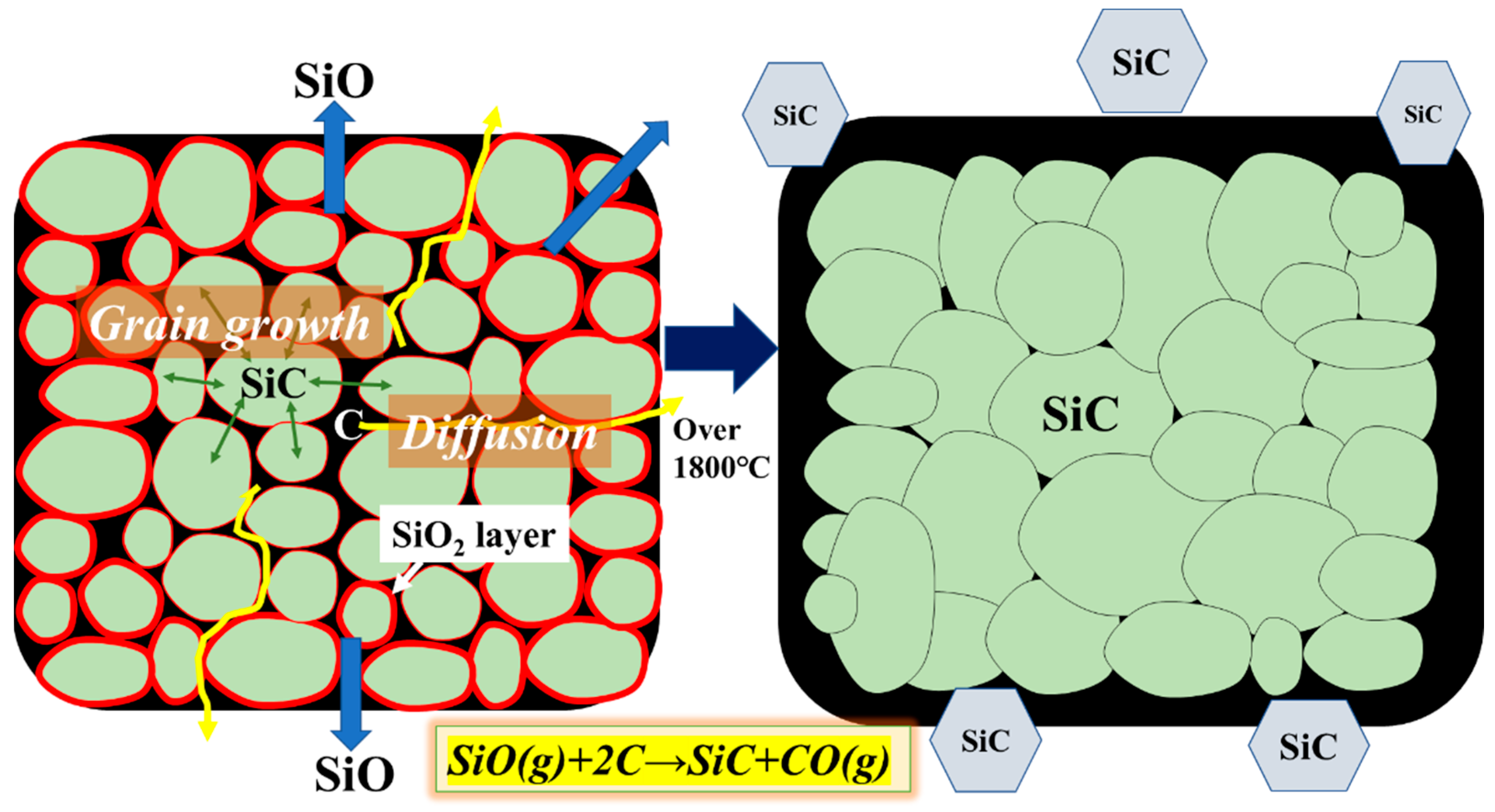
Figure 11 shows the estimated process of the morphological changes in Hi Nicalon Type S that occurred due to the heat treatment at temperatures above 1800 °C for 10 h in an argon atmosphere. As mentioned above, at temperatures above 1500 °C, excess carbon was readily transported from the interior to the exterior through the oxidized SiC grain boundary covered with crystalized SiO2 (cristobalite); at higher temperatures over 1740 °C, vaporized SiO gas from the molten SiO2 layer reacted with surface carbon in accordance with the abovementioned reaction. We believe that the morphological changes in Hi Nicalon Type S at temperatures above 1800 °C were caused by the above-mentioned process. However, we concluded that the sintered, dense grain boundaries of the Tyranno SA fibers could maintain its microstructure at temperatures above 1800 °C. Thus, the most crucial factor in establishing the highest heat resistance is a stable crystalline structure densified by the sintering process.

4. Conclusions

In this paper, we discussed differences in the heat resistance of third-generation SiC polycrystalline fibers (sintered fiber (Tyranno SA) and non-sintered fiber (Hi-Nicalon Type S)). These fibers showed remarkable differences in their heat resistance. At temperatures above 1800 °C, the non-sintered fiber underwent structural changes, including the formation of a surface carbon layer and abnormal SiC grain growth, whereas the sintered fiber maintained its stable polycrystalline structure. The differences in heat resistance between the sintered and non-sintered fibers are believed to be caused by differences in their production processes and microstructures. Hi Nicalon Type S was synthesized using melt spinning, electron beam irradiation under He, heat treatment at 800 °C in an hydrogen atmosphere, and further heat treatment in argon atmosphere at higher temperatures. Sintering was not performed during the production process. This results in defective grain boundaries in Hi Nicalon Type S. Accordingly, the oxidation of each SiC grain constructing Hi Nicalon Type S easily proceeds in air. A thin SiO2 layer formed at the grain boundaries of the SiC grains. The formed SiO2 layer is crystalized at temperatures above 1470 °C to prevent carbothermal reduction and facilitate the easy transformation of excess carbon from the interior to the surface throughout the grain boundary. However, at higher temperatures above 1740 °C, SiO is vaporized from the molten SiO2 layer. For these reasons, morphological changes in Hi Nicalon Type S were considered to proceed easily at the surface at temperatures above 1800 °C.
Finally, we present our perspective on the next generation of heat-resistant SiC fibers (Figure 12). By reducing the defect size to less than 50 nm, the tensile strength will increase to more than 6 GPa. The sintering process is the most important factor for establishing a high heat resistance.

Funding

This study was funded by a Grant-in-Aid for Scientific Research (C) (25k08271) from the Japan Society for the Promotion of Science.

Data Availability Statement

The original contributions presented in this study are included in the article. Further inquiries can be directed to the corresponding author.

Acknowledgments

This study was funded by a Grant-in-Aid for Scientific Research (C) from the Japan Society for the Promotion of Science. We gratefully acknowledge this financial support.

Conflicts of Interest

The author declares no conflict of interest.

References

  1. Yajima, S.; Okamura, K.; Hayashi, J.; Omori, M. Synthesis of Continuous SiC Fibers with High Tensile Strength. J. Am. Ceram. Soc. 1976, 59, 324–327. [Google Scholar] [CrossRef]
  2. Munch, E.; Launey, M.E.; Alsem, D.H.; Saiz, E.; Tomsia, A.P.; Ritchie, R.O. Tough, Bio-Inspired Hybrid Materials. Science 2008, 322, 1516–1520. [Google Scholar] [CrossRef] [PubMed]
  3. Suresh, S. Graded Materials for Resistance to Contact Deformation and Damage. Science 2001, 292, 2447–2451. [Google Scholar] [CrossRef] [PubMed]
  4. Li, J.; Rui, J.; Li, Y.; Qiu, Y.; Hongli, L.; Tian, H. Zr-doped SiOC ceramics fibers and the high-temperature thermal performance. Int. J. Appl. Ceram. Technol. 2023, 20, 2438–2448. [Google Scholar] [CrossRef]
  5. Shimoda, K.; Hinoki, T. Effect of BN nanoparticle content in SiC matrix on microstructure and mechanical properties of SiC/SiC composites. Int. J. Appl. Ceram. Technol. 2023, 20, 2466–2477. [Google Scholar] [CrossRef]
  6. Terrani, K.; Jolly, B.; Trammell, M. 3D printing of high-purity silicon carbide. J. Am. Ceram. Soc. 2020, 103, 1575–1581. [Google Scholar] [CrossRef]
  7. Chen, Y.; Ai, S.; Wang, P.; Fang, D. A physically based thermos-elastoplastic constitutive model for braided CMCs-SiC at ultra-high temperature. J. Am. Ceram. Soc. 2022, 105, 2196–2208. [Google Scholar] [CrossRef]
  8. Barbosa, L.C.M.; Lorrette, C.; Bras, S.L.; Baranger, E.; Lamon, J. Tensile strength analysis and fractography on single nuclear grade SiC fibers at room temperature. J. Nucl. Mater. 2023, 576, 154256. [Google Scholar] [CrossRef]
  9. Eckel, Z.C.; Zhou, C.; Martin, J.H.; Jacobsen, A.J.; Carter, W.B.; Schaedler, T.A. Additive manufacturing of polymer-derived ceramics. Science 2016, 351, 58–62. [Google Scholar] [CrossRef] [PubMed]
  10. Wang, P.; Gou, Y.; Wang, H.; Wang, Y. Revealing the formation mechanism of the skin-core structure in nearly stoichiometric SiC fiber. J. Euro. Ceram. Soc. 2020, 40, 2295–2305. [Google Scholar]
  11. Ishikawa, T.; Kohtoku, Y.; Kumagawa, K.; Yamamura, T.; Nagasawa, T. High-strength alkali-resistant sintered SIC fibre stable to 2200 °C. Nature 1998, 391, 773–775. [Google Scholar] [CrossRef]
  12. Ishikawa, T.; Yamaoka, H.; Harada, Y.; Fujii, T.; Nagasawa, T. A general process for in situ formation of functional surface layers on ceramics. Nature 2002, 416, 64–67. [Google Scholar] [CrossRef] [PubMed]
  13. Lipowitz, J.; Barnard, T.; Bujalski, D.; Rabe, J.; Zank, G.; Zangvil, A.; Xu, Y. Fine-diameter polycrystalline SiC fibers. Compos. Sci. Technol. 1994, 51, 167–171. [Google Scholar]
  14. Ishikawa, T.; Kajii, S.; Matsunaga, K.; Hogami, T.; Kohtoku, Y.; Nagasawa, T. A tough, thermally conductive silicon carbide composite with high strength up to 1600 °C in air. Science 1998, 282, 1295–1297. [Google Scholar] [CrossRef] [PubMed]
  15. Takeda, M.; Urano, A.; Sakamoto, J.; Imai, Y. Microstructure and Oxidation Behavior of Silicon Carbide Fibers Derived from Polycarbosilane. J. Am. Ceram. Soc. 2000, 83, 1171–1176. [Google Scholar] [CrossRef]
  16. Yajima, S.; Hayashi, J.; Omori, M.; Okamura, K. Development of a silicon carbide fibre with high tensile strength. Nature 1976, 261, 683–685. [Google Scholar] [CrossRef]
  17. Ichikawa, H. Polymer-derived ceramic fibers. Annu. Rev. Mater. Res. 2016, 46, 335–356. [Google Scholar] [CrossRef]
  18. Rahaman, M.N. Sintering of Ceramics (Taylor & Francis Group, 2008); CRC Press: Boca Raton, FL, USA, 2007; pp. 27–28. [Google Scholar]
  19. Braun, J.; Sauder, C. Mechanical behavior of SiS/SiC composites reinforced with new Tyranno SA4 fibers: Effect of interface thickness and comparison with Tyranno SA3 and Hi-Nicalon S reinforced composites. J. Nucl. Mater. 2022, 558, 153367. [Google Scholar] [CrossRef]
  20. Bhatt, R.T.; Halbig, M.C. Creep properties of melt infiltrated SiC/SiC composites with Sylramic-iBN and Hi-Nicalon S fibers. Int. J. Appl. Ceram. Tech. 2022, 19, 1074–1091. [Google Scholar] [CrossRef]
  21. Lamon, J. Handbook of Ceramic Composites; Springer: Berlin/Heidelberg, Germany, 2005; pp. 55–76. [Google Scholar]
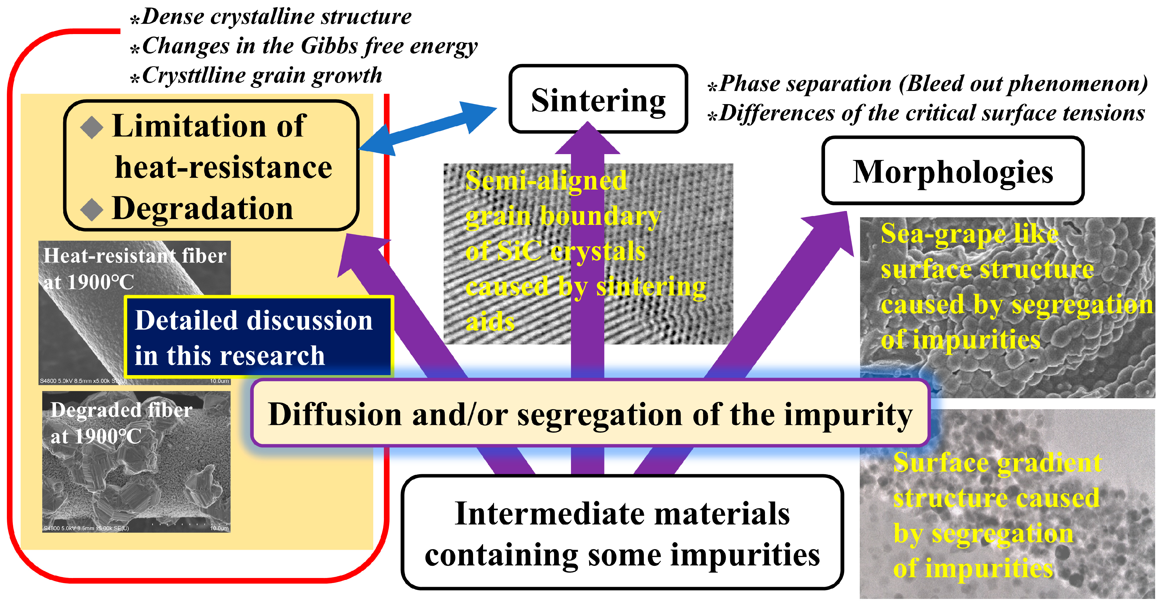
Figure 1. Some characteristics of Si-based ceramics dominated by impurities.
Ceramics 08 00120 g001
Figure 2. Production process of Tyranno SA.
Ceramics 08 00120 g002
Figure 3. Production process of Hi Nicalon Type S.
Ceramics 08 00120 g003
Figure 4. TEM images of non-sintered SiC polycrystalline fiber (a) and sintered SiC polycrystalline fibers (b,c).
Ceramics 08 00120 g004
Figure 5. Auger depth profiles of Tyranno SA3 (A) and Hi-Nicalon Type S (B).
Ceramics 08 00120 g005
Figure 6. Changes in the Gibb’s free energies of the estimated reactions.
Ceramics 08 00120 g006
Figure 7. The result of EDS at the grain boundary of Hi-Nicalon Type S. Oxygen is emphasized by red box.
Ceramics 08 00120 g007
Figure 8. SEM images of the specimen surfaces after heat treatment at high temperatures (1600~1900 °C) for 10 h in an argon atmosphere.
Ceramics 08 00120 g008
Figure 9. SEM images of surface region of the non-sintered fiber (Hi-Nicalon Type S) after heat treatment at high temperatures (1700~1900 °C) for 10 h in an argon atmosphere.
Ceramics 08 00120 g009
Figure 10. SEM images of surface region of the sintered fibers (Tyranno SA 3, Tyranno SA 4) after heat treatment at high temperatures (1700~1900 °C) for 10 h in an argon atmosphere.
Ceramics 08 00120 g010
Figure 11. Estimated process of the morphological changes in Hi Nicalon Type S that occurred due to the heat treatment at temperatures above 1800 °C for 10 h in an argon atmosphere.
Ceramics 08 00120 g011
Figure 12. Image depicting development of future heat-resistant SiC fibers.
Ceramics 08 00120 g012
Disclaimer/Publisher’s Note: The statements, opinions and data contained in all publications are solely those of the individual author(s) and contributor(s) and not of MDPI and/or the editor(s). MDPI and/or the editor(s) disclaim responsibility for any injury to people or property resulting from any ideas, methods, instructions or products referred to in the content.