Article

Sustainable Use of Gypsum Waste for Applications in Soil–Cement Bricks: Mechanical, Environmental, and Durability Performance

by
Elvia Soraya Santos Nascimento
1,
Herbet Alves de Oliveira
2,
Cochiran Pereira dos Santos
3,
Maria de Andrade Gomes
3,
Mário Ernesto Giroldo Valerio
1 and
Zélia Soares Macedo
1,*
1
Postgraduate Program in Materials Science, Federal University of Sergipe, São Cristóvão 49107-230, SE, Brazil
2
Department of Civil Engineering, Federal Institute of Sergipe, Aracaju 49055-260, SE, Brazil
3
Physics Department, Federal University of Sergipe, São Cristóvão 49107-230, SE, Brazil
*
Author to whom correspondence should be addressed.
Ceramics 2025, 8(3), 83; https://doi.org/10.3390/ceramics8030083
Submission received: 31 March 2025 / Revised: 27 June 2025 / Accepted: 27 June 2025 / Published: 1 July 2025
(This article belongs to the Special Issue Ceramics in the Circular Economy for a Sustainable World)

Abstract

This study investigates the use of gypsum waste from civil construction as a partial substitute for cement in soil–cement formulations, aiming to produce eco-friendly bricks aligned with circular economy principles. Formulations were prepared using a 1:8 cement–soil ratio, with gypsum replacing cement in proportions ranging from 5% to 40%. The raw materials were characterized in terms of chemical composition, crystalline phases, plasticity, and thermal behavior. Specimens, molded by uniaxial pressing into cylindrical bodies and cured for either 7 or 28 days, were evaluated for compressive strength, water absorption, durability, and microstructure. Water absorption remained below 20% in all samples, with an average value of 16.20%. Compressive strength after 7 days exhibited a slight reduction with increasing gypsum content, ranging from 16.36 MPa (standard formulation) to 13.74 MPa (40% gypsum), all meeting the quality standards. After 28 days of curing, the formulation containing 10% gypsum achieved the highest compressive strength (26.7 MPa), surpassing the reference sample (25.2 MPa). Mass loss during wetting–drying cycles remained within acceptable limits for formulations incorporating up to 20% gypsum. Notably, samples with 5% and 10% gypsum demonstrated superior mechanical performance, while the 20% formulation showed performance comparable to the standard formulation. These findings indicate that replacing up to 20% of cement with gypsum waste is a technically and environmentally viable approach, supporting sustainable development, circular economy, and reduction of construction-related environmental impacts.

1. Introduction

In recent years, sustainable practices have gained prominence across various sectors, due to the urgent need to preserve natural resources and mitigate environmental impacts. The concept of sustainable development, as defined by the United Nations (UN) World Commission on Environment and Development in 1983, emphasizes the importance of meeting present needs without compromising the ability of future generations to meet their own. To achieve this goal, it is essential to manage key elements in production chains by reducing the consumption of natural resources, minimizing energy use, decreasing waste generation, and promoting reuse and recycling. Solid waste management plays a critical role in advancing the UN’s Sustainable Development Goals (SDGs), particularly SDG 11 (Sustainable Cities and Communities), SDG 12 (Responsible Consumption and Production), and SDG 13 (Climate Action), by enabling resource recovery and fostering circular economy strategies [1,2].
The construction sector is one of the most impactful industries in terms of resource consumption and waste generation. In response, the industry has increasingly adopted innovative practices to embed sustainability into its production chain [3]. A notable advancement is the use of eco-friendly materials, such as soil–cement bricks, which offer a cost-effective and environmentally conscious alternative to conventional masonry materials. These bricks can be produced on site using locally sourced materials, thereby reducing transportation demands and associated energy consumption [4]. Further contributions to the sustainability of soil–cement bricks include the incorporation of recycled aggregates and industrial by-products [5], as well as the partial substitution of traditional binders such as Portland cement with alternative materials [6,7]. However, challenges remain in optimizing production processes to meet the required standards for compressive strength and durability [5,8]. Recent studies have explored the addition of different waste materials to soil–cement bricks, such as coffee husks, paper and pulp industry waste, sugarcane bagasse ash, and leather powder, with varied outcomes regarding their technical viability [9,10,11].
One underexplored waste material in this context is gypsum, which is a major byproduct of civil construction. The global gypsum production ranges from 30 to 150 million tons annually [12], with Brazil accounting for approximately 1.3 million tons [13]. It is estimated that up to 47% of gypsum used in coatings, drywall cutting, and demolition ends up discarded [14]. Recycling gypsum is challenging due to sulfate contamination and landfill emissions [15], yet it remains essential to reduce resource depletion and environmental risks [16].
Existing studies have primarily focused on reusing gypsum waste in plasters and mortars, typically as a partial replacement for either conventional gypsum or Portland cement [17,18]. However, its application in soil–cement bricks remains unexplored. Moreover, there is a notable gap in the literature regarding the effects of gypsum waste on the mechanical properties, microstructure, and long-term durability of construction materials. In this context, the present study aims to determine safe and effective incorporation levels of gypsum waste in soil–cement bricks by evaluating their physical, mechanical, and microstructural properties across varying proportions of recycled gypsum.

2. Materials and Methods

2.1. Raw Materials

The materials used in this study were: natural soil, Portland cement (CP V-ARI), and gypsum waste from construction activities. The soil was collected from northeastern Brazil and has a friable texture, light reddish color, and is commonly used in local construction. After collection, it was dried in an oven at 60 ± 5 °C. The particle size distribution was determined according to ASTM D6913/D6913M [19], with approximately 40% of the material passing through a 0.075 mm sieve. The specific gravity was measured using the pycnometer method, following DNER-ME-093/94 [20]. Atterberg limits, determined according to ASTM D4318 [21], yielded a liquid limit (LL) of 32% and a plasticity index (PI) of 8.0. The plasticity index (PI) of the soil was 8.0, and the liquid limit (LL) was 32%, classifying it as a medium-plasticity material, considered suitable for soil–cement brick production [22,23]. According to ABCP (1985) and NBR 10833 [24], suitable soils for soil–cement brick production must have LL < 45% and PI < 18%. The soil used in this study satisfies these requirements. Based on these parameters, it is classified as a low- to medium-plasticity inorganic clay (CL) under the Unified Soil Classification System (USCS), and as A-2-6 in the Transportation Research Board (TRB) system—granular soils with clayey fine fractions that influence plastic behavior.
The cement used was CP V-ARI, a high early strength Portland cement suitable for precast and fast-setting applications. It was characterized for initial and final setting times (ASTM C191 [25]), specific gravity (ASTM C188 [26]), specific surface area using the Blaine air permeability method (NBR 16372 [27]), and compressive strength (ASTM C109/C109M [27]).
The gypsum waste was collected from companies manufacturing and installing prefabricated gypsum boards. It consisted mainly of calcium sulfate hemihydrate (CaSO4·0.5 H2O), typically used in interior coatings. During construction, this material is hydrated to form calcium sulfate dihydrate (CaSO4·2H2O). The collected waste was crushed to approximately 1 cm, oven-dried at 60 ± 5 °C to remove residual moisture, and then ground using a ball mill. The resulting powder was sieved through a No. 100 ASTM mesh (150 µm) and stored in sealed plastic containers to prevent moisture uptake and carbonation. No chemical treatments were applied.
The decision to use this material was based on its local abundance and chemical similarity to commercial gypsum. Its reuse aligns with sustainability principles by reducing landfill disposal and promoting circular economy practices.

2.2. Specimen Preparation

Specimens weighing 200 g were uniaxially pressed into cylindrical shapes with approximate dimensions of 6 cm in diameter and 4 cm in height, using a moisture content of 10%, as reported in the literature [28,29,30,31,32]. The initial formulations contained 90% soil and 10% cement. However, specimens prepared with this mixture did not meet the minimum compressive strength required by the standard (2 MPa). To improve performance, part of the soil was replaced with fine aggregate (sand), and the compaction pressure was varied to identify optimal conditions. Figure 1 presents the compressive strength of specimens with different sand-to-soil ratios, pressed at 5 MPa, 10 MPa, and 15 MPa. The results indicate that the formulation containing 10% sand, 80% soil, and 10% cement, compacted at 10 MPa, yielded the highest compressive strength among the combinations tested.
After molding, the specimens were air-cured under natural environmental conditions, with room temperature of approximately 25 °C and relative humidity ranging from 70% to 82%. No artificial humidification system was used. The samples were stored in a sheltered area, protected from direct sunlight and wind, following NBR 8492 [33]. This curing method reflects common practices in the construction industry and allows a realistic evaluation of performance under local conditions.
Five formulations were prepared, incorporating varying proportions of gypsum residue as a partial replacement for cement. The compositions are shown in Table 1. The reference formulation without gypsum was labeled SF (standard formulation), and the gypsum-containing mixes were designated G5, G10, G20, and G40, corresponding to 0.5%, 1%, 2%, and 4% gypsum, respectively.

2.3. Mineralogical and Chemical Characterization

X-ray diffraction (XRD) patterns of the cement, gypsum, and soil samples were obtained using a Rigaku DMAX 100 diffractometer (Tokyo, Japan) with CuKα radiation (λ = 1.5418 Å). Scans were performed in continuous mode over a 2θ range of 5° to 70° at a scan rate of 1°/min. The crystalline phases were identified by comparing experimental patterns with the ICSD crystallographic database.
Chemical composition analysis was performed using energy-dispersive X-ray fluorescence (EDXRF) with a Shimadzu EDX-7000 spectrometer (Kyoto, Japan) under vacuum, using a 10 mm collimator and Mylar capsule both supplied by the equipment manufacturer. Operating conditions included voltages of 50 kV (Al-U) and 15 kV (Na-Sc), with a 100 s acquisition time and ~30% dead time.

2.4. Thermal Analysis

Thermogravimetric analysis (TGA) of the soil was conducted using a TA Instruments SDT Q600 (New Castle, DE, USA) under a nitrogen atmosphere. Approximately 10 mg of sample was heated in a platinum crucible at a rate of 10 °C/min from room temperature to 1000 °C.

2.5. Scanning Electron Microscopy (SEM) Procedures

The morphology of the soil–cement composites after 28 days of curing was analyzed using a JEOL JSM-6510LV scanning electron microscope (SEM) (Akishima, Japan) at CMNano/UFS (Proposal #080/2023). For these analyses, the samples were dried at 60 ± 5 °C to remove residual moisture and manually fractured to expose the internal microstructure. The fractured surfaces were mounted on metallic stubs using carbon tape and coated with a thin layer of gold using a sputter coater to minimize charging effects and ensure adequate image quality. This preparation method enabled clear microstructural visualization and reliable elemental analysis under high-vacuum conditions. The SEM operated at 15 kV in secondary electron imaging (SEI) mode.

2.6. Mechanical and Physical Testing

2.6.1. Compressive Strength Test

The compressive strength of the cylindrical specimens was evaluated after 7 and 28 days of curing using a Contenco HD-200T hydraulic press (São José da Lapa, Brazil) with a maximum load capacity of 2000 kN. The loading rate was kept between 1.0 MPa/s and 1.5 MPa/s, in line with the guidelines of NBR 5739 [34]. Tests were conducted on five samples per formulation. The results are presented as mean values with standard deviations. Compressive strength tests were performed at 7 and 28 days of curing for all formulations. Intermediate curing ages (e.g., 14 days) were not included in this study, as the focus was on early-age and long-term mechanical performance.

2.6.2. Water Absorption and Apparent Density

Water absorption and apparent density were measured after 28 days of curing, in accordance with NBR 8492 [35] and using three specimens per formulation. The dry mass (M) was first recorded, followed by immersion in distilled water for 24 h to determine the wet mass (MW). Water absorption was calculated as the difference between wet and dry mass (NBR 10836 [36]). Apparent density (Db) was calculated as the ratio between dry mass and volume (Db = M/V), where the volume was determined from direct measurements of height and diameter, with 0.02 mm precision. Water absorption tests were performed on five specimens per formulation, and the results are presented as mean values with standard deviations.

2.6.3. Durability Test Under Wet–Dry Cycles

Durability was assessed by simulating weather exposure through alternating wetting and drying cycles (NBR 13554 [37]). Three specimens from each formulation were immersed in water for 6 h and then oven-dried for 18 h at 70 °C. This procedure was repeated for six cycles, and the mass loss was recorded before and after each cycle (NBR 8492 [34]). Durability-related tests were conducted on five specimens for each composition, and the results were expressed as mean values and standard deviations.

2.7. Statistical Analysis

The normality of the data was verified, and a one-way analysis of variance (ANOVA) was conducted to assess the influence of different gypsum substitution levels (0%, 5%, 10%, 20%, and 40%) on compressive strength and water absorption at 7 and 28 days of curing. Statistical analysis was conducted using Paleontological Statistics (PAST) software version 4.13 [38], with a significance level (p-value) of ≤0.05.
The null hypothesis (H0) assumed that there were no statistically significant differences among the treatment group means, while the alternative hypothesis (H1) posited that at least one group mean differed significantly. When ANOVA results indicated significance (p < 0.05), Tukey’s post-hoc test was applied to identify specific group pairs with statistically significant differences.
These statistical procedures were essential to support the interpretation of the experimental results and ensure the reliability of the conclusions drawn from the data.

3. Results

3.1. Physical and Chemical Characterization of Raw Materials

Table 2 presents the specific density, bulk density, and specific surface area of the raw materials, which were obtained from triplicate measurements and are reported as mean values with standard deviations. The soil showed a specific density of 2.71 g/cm3, which suggests the presence of dense minerals such as quartz or iron oxides. Materials with high specific density generally exhibit lower porosity, a factor that can positively influence mechanical strength [39]. The values obtained for cement and sand fall within the typical range for these materials. Regarding specific surface area, cement and soil showed similar values, while the gypsum residue exhibited a significantly higher value. This indicates that the gypsum particles are smaller and more uniformly distributed, which may influence hydration kinetics, mechanical strength, and durability in cementitious systems [40].
Table 3 provides the chemical composition of the materials, obtained via EDXRF. The soil is predominantly composed of silica (SiO2—39.39%), with relevant amounts of calcium oxide (CaO—22.97%), iron oxide (Fe2O3—18.45%), and alumina (Al2O3—9.40%). The organic matter content, estimated by loss-on-ignition (LOI), was 0.64%. These values are consistent with compositions containing clay minerals, quartz, feldspars, and limestone [41,42]. A SiO2/Al2O3 ratio of 4.33 suggests a high proportion of free quartz and accessory minerals. The presence of alkaline oxides (Na2O + K2O) indicates feldspars or mica [40]. Silica contributes to drying and reduces plasticity, while alumina improves thermal stability and cohesion [41]. Cement was mainly composed of calcium oxide (CaO—80.95%), with smaller fractions of silica (SiO2—8.46%) and iron oxide (Fe2O3—5.95%). Sand consisted mostly of silica (SiO2—89.79%), and gypsum was primarily composed of calcium oxide (CaO—68.01%) and sulfur trioxide (SO3—29.97%).

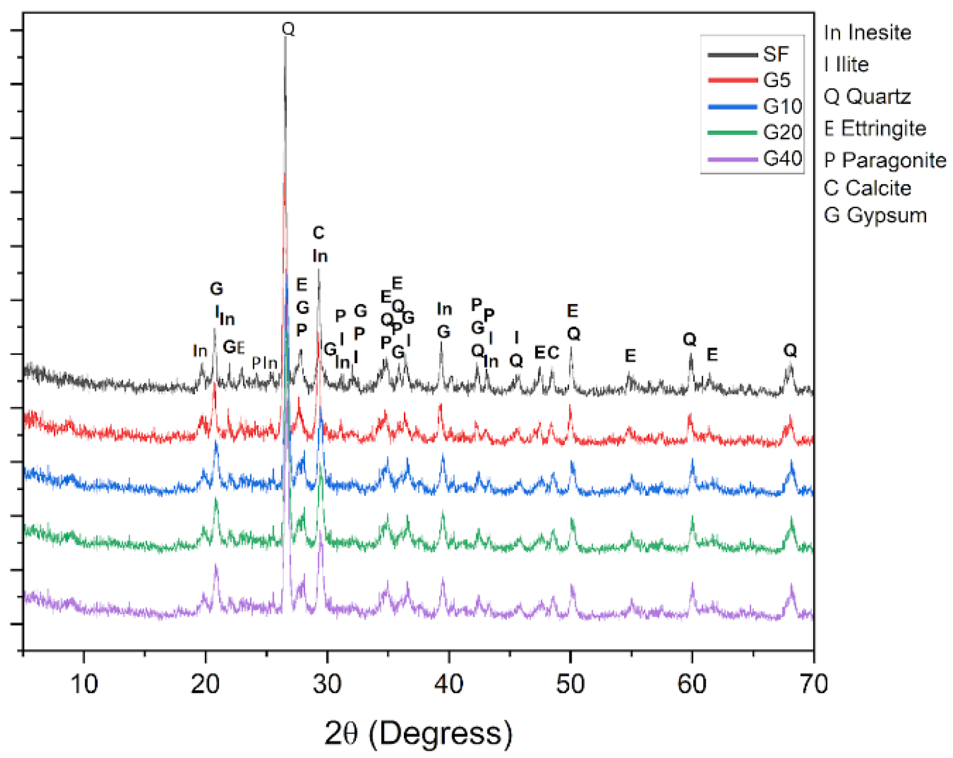
3.2. Mineralogical and Phase Analysis

Figure 2 presents the XRD patterns of soil, cement, and gypsum. Cement exhibited characteristic peaks of alite (C3S) and larnite (C2S), confirming its expected mineralogy [43]. The gypsum sample was predominantly composed of calcium sulfate hemihydrate (CaSO4·0.5 H2O—80.8%), with 19.2% calcium sulfate dihydrate and minor peaks of anhydrous calcium sulfate [44,45]. The soil showed quartz as the dominant mineral (30.8–61.7%), followed by illite and calcite, consistent with literature findings [46,47].
Figure 3 displays the X-ray diffraction patterns of the soil–cement formulations with varying contents of recycled gypsum. The presence of crystalline phases such as quartz (Q), calcite (C), gypsum (G), ettringite (E), illite (I), paragonite (P), and inesite (In) was identified. Ettringite formation becomes more pronounced in the samples with higher gypsum content, indicating the influence of calcium sulfate addition on the hydration process. The persistence of gypsum peaks in the formulations containing recycled gypsum also confirms the presence of unreacted sulfate, particularly in mixtures with higher replacement levels. These results support the role of gypsum in modifying the mineralogical composition of the composite and suggest potential effects on its microstructure and mechanical performance, as discussed in the following sections.
The crystalline phases observed in Figure 3 were quantitatively estimated using Match! Software version 4.2 Build 324, and summarized in Table 4. The presence of crystalline phases such as quartz, paragonite, inesite, ettringite, calcite, gypsum, and illite was confirmed. The absence of portlandite (Ca(OH)2) may be due to its consumption in pozzolanic reactions involving silica, alumina, and iron oxide, forming phases like C-S-H, C-A-S-H, and C-A-F-H [48,49]. Portlandite may also be present in amorphous form or have been consumed by carbonation, forming calcite [50,51].

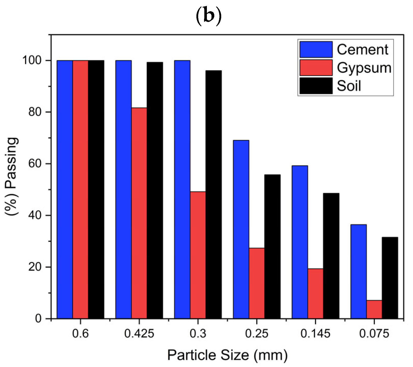
3.3. Particle Size Distribution and Plasticity

Figure 2 shows the particle size distribution of the raw materials. Proper grading is essential to optimize compaction, reduce porosity, and improve strength. According to ABCP (1985) and NBR 10833 [24], soils suitable for producing soil–cement bricks must meet the following criteria: 100% of the soil must pass through a No. 4 sieve (4.8 mm), and 10% to 50% of the sample must pass through a No. 200 sieve (0.075 mm). As shown in Figure 4, all materials passed 100% through the No. 4 sieve. For the No. 200 sieve, cement and soil passed approximately 40%, while gypsum passed about 10%. Therefore, all materials meet the granulometric classification requirements.
The plasticity characteristics of the soil play an important role in its suitability for stabilization. Soils with higher plasticity index (PI) generally exhibit reduced compressive strength due to less efficient formation of cementitious compounds, such as C-S-H. In this study, the soil met the PI and LL limits of ABCP (1985) and NBR 10833, as shown in Section 2.1. Its classification under USCS (CL) and TRB (A-2-6) reflects moderate cohesion and favorable compaction behavior.

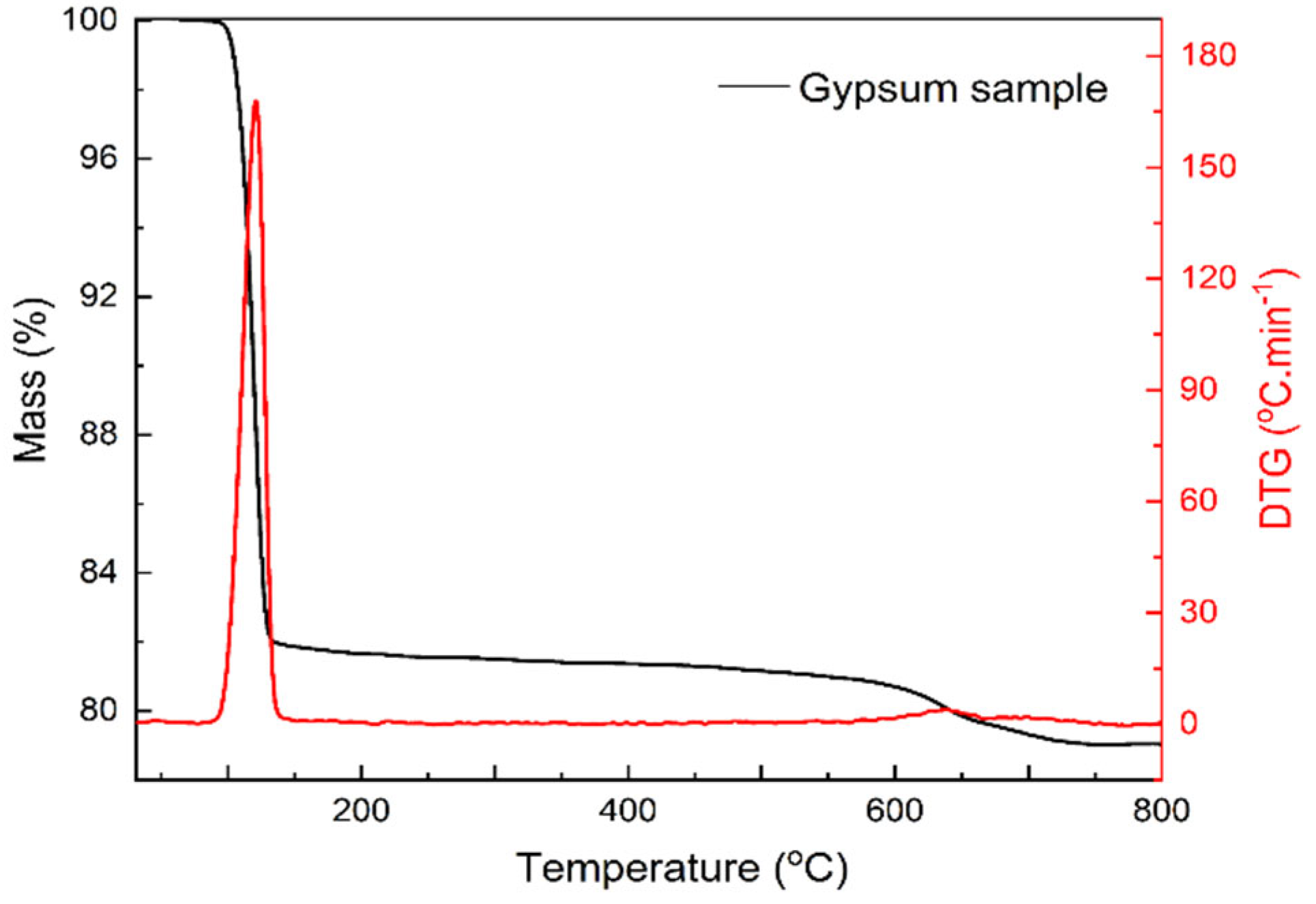
3.4. Thermal Analysis of Gypsum and Soil

Figure 5 and Figure 6 show the TG/DTG curves of gypsum and soil, respectively. For gypsum, a major mass loss occurs at approximately 139 °C, associated with the dehydration of calcium sulfate dihydrate to form hemihydrate (CaSO4·0.5H2O). Between 90 °C and 140 °C, continuous transformations occur, eventually leading to the formation of anhydrite above 170 °C. This process is influenced by environmental conditions such as humidity and the presence of acids or salts, which may accelerate or delay the transformation [52,53].
Above 180 °C, the conversion of anhydrite III to the more stable anhydrite II begins. A secondary mass loss observed near 560 °C may be related to the thermal decomposition of residual impurities in the recycled gypsum, such as contaminant oxides or traces of organic matter. These components may not have been detected in the XRD analysis but are consistent with the EDS and chemical composition data in Table 2. Some authors also associate these events with late-stage dehydration or minor carbonate decomposition [54,55,56,57].
For the soil sample, mass loss below 120 °C is attributed to the evaporation of free water. In the range of 120 °C to 430 °C, the loss corresponds to the release of water bound to exchangeable cations and hydrated mineral phases. Between 430 °C and 600 °C, the decomposition of aluminum silicates occurs, while from 600 °C to 800 °C, the thermal degradation of calcium silicates becomes evident [58].
Although thermal behavior is not directly linked to curing at ambient temperatures, these analyses help to elucidate the stability and reactivity of the phases involved, especially under potential exposure to high temperatures during processing or long-term use. In addition, the distinct dehydration behavior of gypsum confirms its potential for early reactivity, which is consistent with the accelerated ettringite formation observed in microstructural and mechanical analyses (Section 3.5 and Section 3.6).

3.5. Mechanical Performance

3.5.1. Compressive Strength

Figure 7 shows the compressive strength of the specimens at 7 and 28 days, confirming the continued hydration and densification of the matrix. Although no data were collected at 14 days, the increasing trend indicates effective curing progression across formulations. All formulations exceeded the 2 MPa minimum required. The G10 sample (10% gypsum) showed the highest strength (26.5 MPa), surpassing the standard formulation (25.2 MPa). Statistical analysis confirmed significant differences (F = 199.02, p < 0.05). This strength increase is attributed to several synergistic mechanisms. The addition of gypsum introduces sulfate ions (SO42−), which accelerate early hydration of aluminate phases, leading to ettringite formation. Ettringite refines the pore structure and improves matrix connectivity, enhancing strength [37,59,60]. Gypsum also acts as a fine filler, improving particle packing and reducing porosity, contributing to a denser, more homogeneous microstructure. However, this benefit is limited to moderate gypsum contents. Higher replacement levels (e.g., 20% or 40%) increase porosity and create weak zones that reduce strength. G40, for instance, showed a strength of 20 MPa.
Additionally, in systems with high gypsum content, the lack of free CaO—consumed during earlier hydration reactions—may prevent further formation of C-S-H and ettringite. The excess sulfate may behave as an inert phase, further compromising matrix development. Nonetheless, all mixtures demonstrated acceptable compressive strength.
Formulations replacing cement with fly ash and chemically activated slag mixtures showed compressive strength of 25–33 MPa at 28 days, but they required a more intensive processing. This refers mainly to the ultrafine grinding of the materials, thermal curing of the fly ash, preparation of alkaline activating solutions, and controlled use of superplasticizer additives, which demand greater energy input, precise processing steps, and specialized equipment [61,62]. Formulations with ceramic powder or calcined brick waste typically achieve strengths between 15 and 30 MPa, also showing improvements in durability and microstructural refinement [6,63]. Additionally, non-traditional residues such as shredded masks and rubber fibers have shown benefits in terms of toughness and tensile strength in soil–cement composites, although compressive strength usually remains below 22 MPa [64,65]. The high strength obtained for G10 formulation, together with the simplified processing and lower environmental impact, shows that the use of recycled gypsum in soil–cement bricks can technically compete with established residues, offering advantages in sustainability and ease of use.

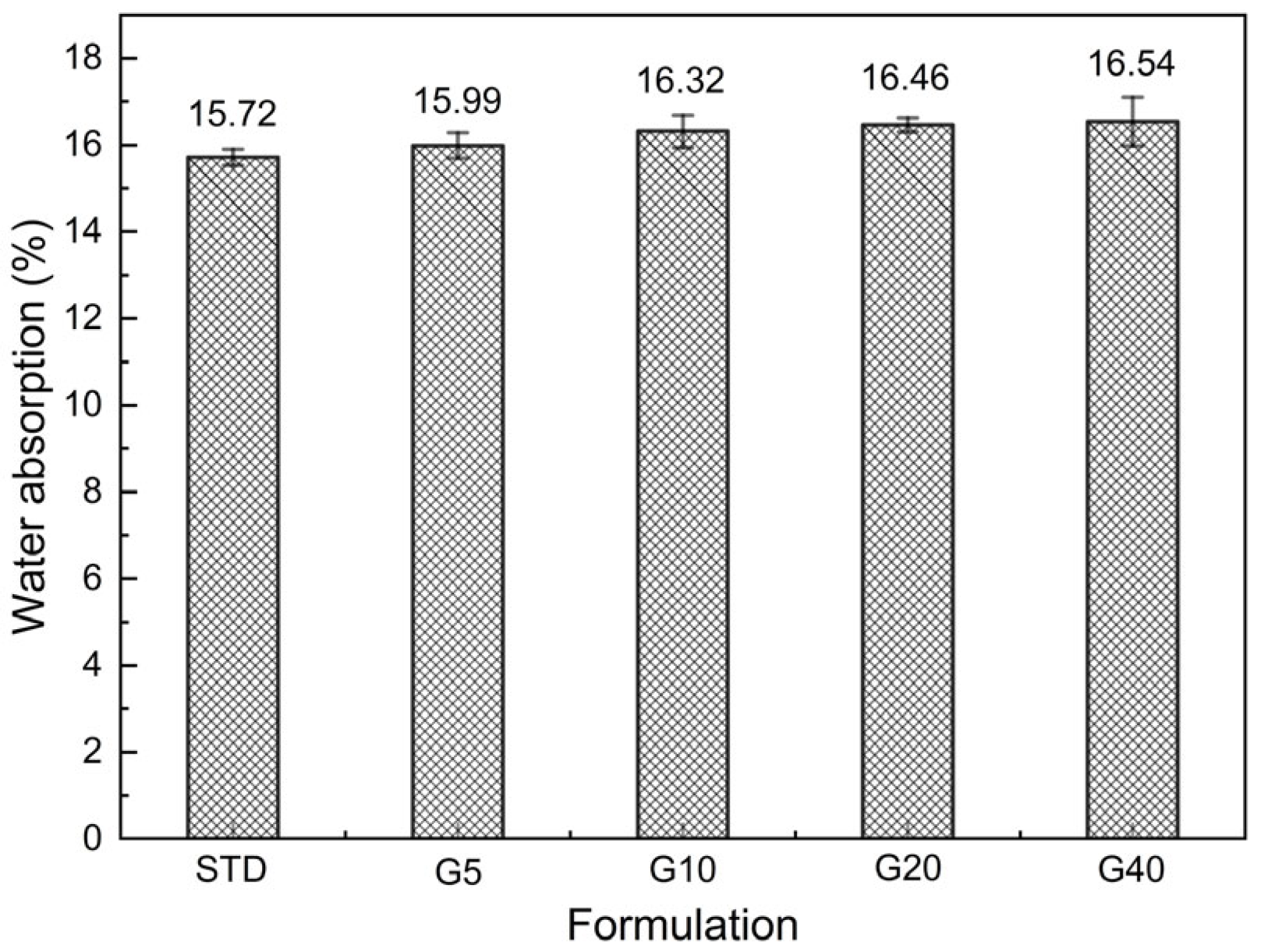
3.5.2. Water Absorption
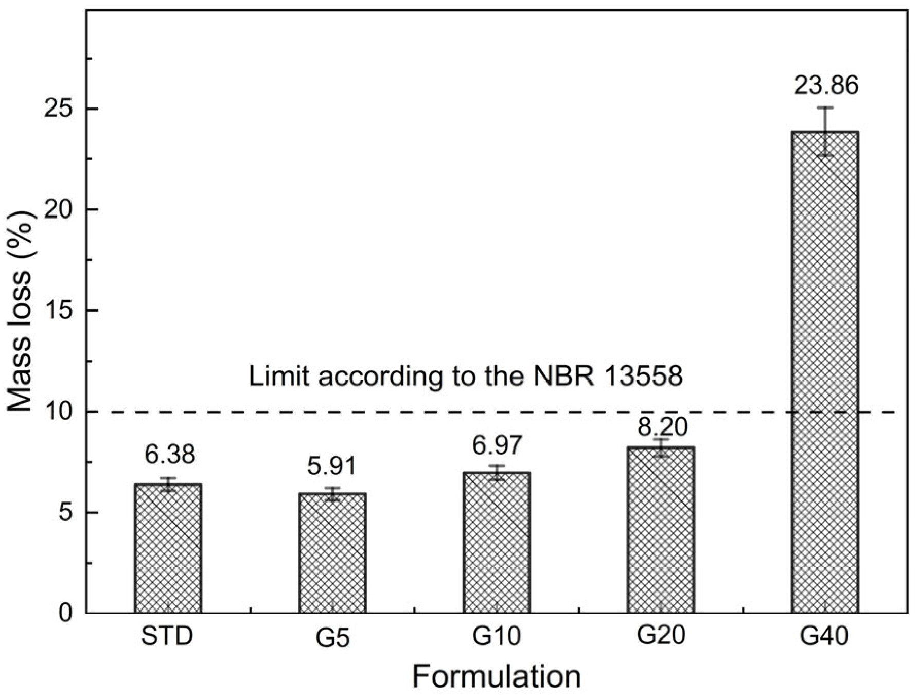
Figure 8 presents the water absorption results for specimens cured for 7 days. Values increased slightly with gypsum content, ranging from 15.71% (SF) to 16.54% (G40). Despite this increase, all values remained below 20%, which is the maximum allowed by NBR 10834 [66], for samples cured for 7 days. Statistical analysis (ANOVA) confirmed a significant difference between the means (F = 332.80, p < 0.05). However, the residue-containing samples present water absorption that complies with the standard, although slightly higher than the result obtained for the SF specimen. The water absorption of soil–cement bricks is directly related to porosity and pore connectivity [67]. The high silica (SiO2—39.39%) content in the soil and the formation of C-S-H (calcium silicate hydrate) contribute to the densification of the material’s microstructure, reducing pore connectivity and, consequently, water absorption. Additionally, the chemical reaction of cement with aluminosilicates in the soil leads to the formation of cementitious products such as C-S-H and C-A-S-H (calcium aluminosilicate hydrate), which bind the particles and minimize pore interconnectivity [68,69].
With the partial replacement of cement by gypsum, there is a reduction in the formation of dense hydration products, which may explain the increased porosity and water absorption in gypsum-based formulations. This is consistent with findings in the literature, which report higher pore connectivity in composites with increased gypsum content due to limited formation of compact hydrates [70]. Recycled gypsum composites also tend to exhibit greater water uptake and reduced water resistance, especially when unreacted particles or agglomerates are present in the microstructure [71].
Physical aspects also contribute to this behaviour. Gypsum particles are generally angular and less spherical than cement grains, which reduces particle packing efficiency and generates additional capillary pores within the matrix [39]. Moreover, the mismatch in shrinkage between the gypsum and the surrounding matrix can lead to microcracking, thereby contributing to an increase in interconnected porosity [72]. These chemical, microstructural, and physical mechanisms together explain the statistically significant increase in water absorption observed with higher gypsum content, while still remaining within acceptable limits.

3.5.3. Durability

Figure 9 shows the durability results of the specimens cured for 28 days and evaluated by mass loss after six wetting and drying cycles. Samples SF, G5, G10, and G20 remained below the 10% mass loss limit defined by NBR 13553 [73] for A-2-6 soils. In contrast, G40 exhibited a loss of 23.86%, indicating compromised durability. This behavior is associated with excessive ettringite formation in high-sulfate systems. While moderate ettringite content improves early strength by filling pores, excess leads to expansion and cracking. Studies show that when ettringite forms in small capillary pores, it can cause swelling and structural degradation [74,75]. Conversely, the presence of SiO2 and Al2O3 in the soil promotes formation of stable C-S-H and C-A-S-H phases, less susceptible to leaching. These phases enhance microstructural stability and reduce water ingress. Thus, in formulations with lower gypsum content, pozzolanic reactions dominate, leading to durable structures.
The balance between ettringite formation and matrix densification is critical. Up to 20% gypsum maintained integrity, but 40% substitution disrupted the structure. The mechanical and absorption data corroborate these findings, highlighting the role of sulfate levels in durability performance.

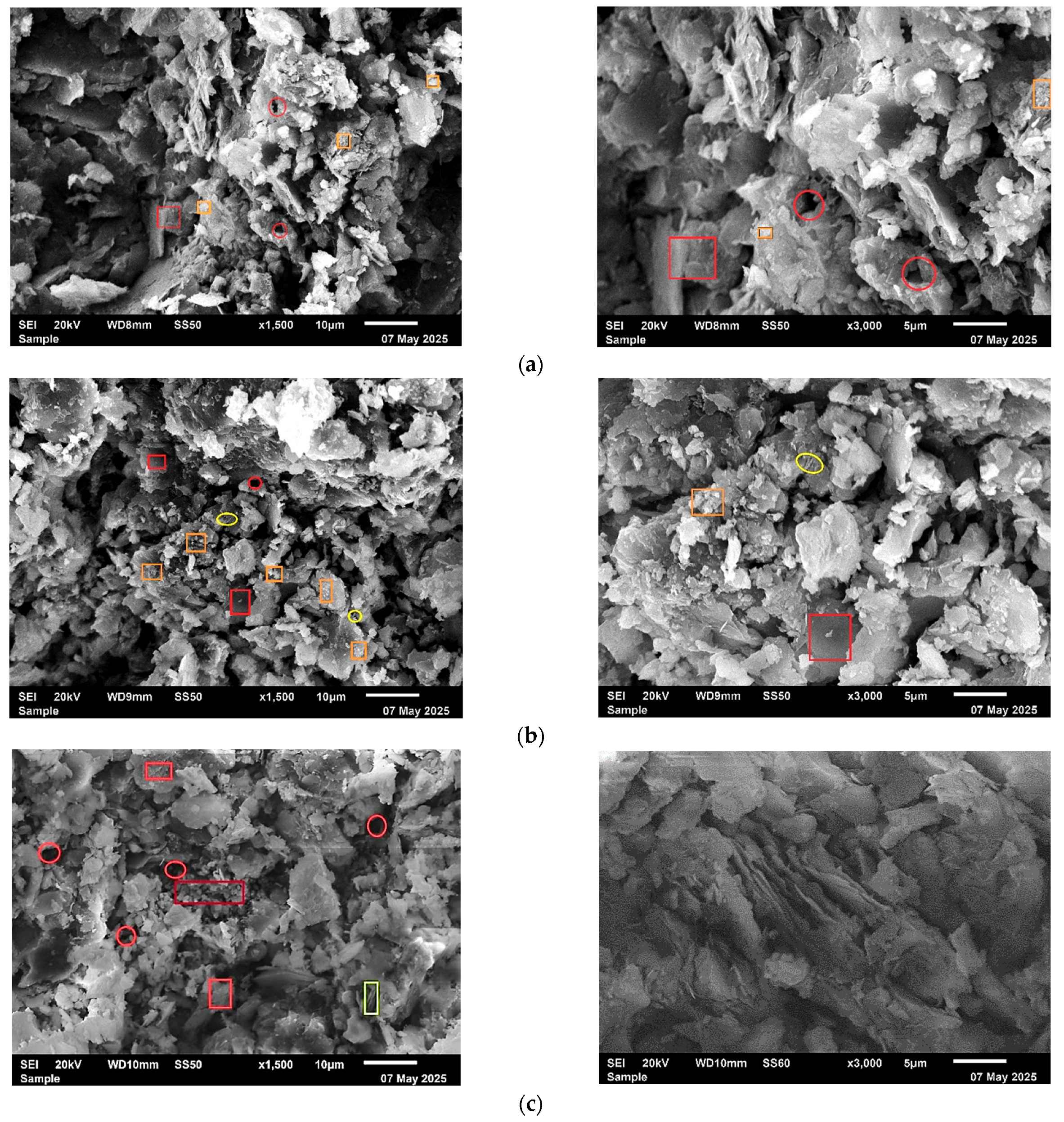
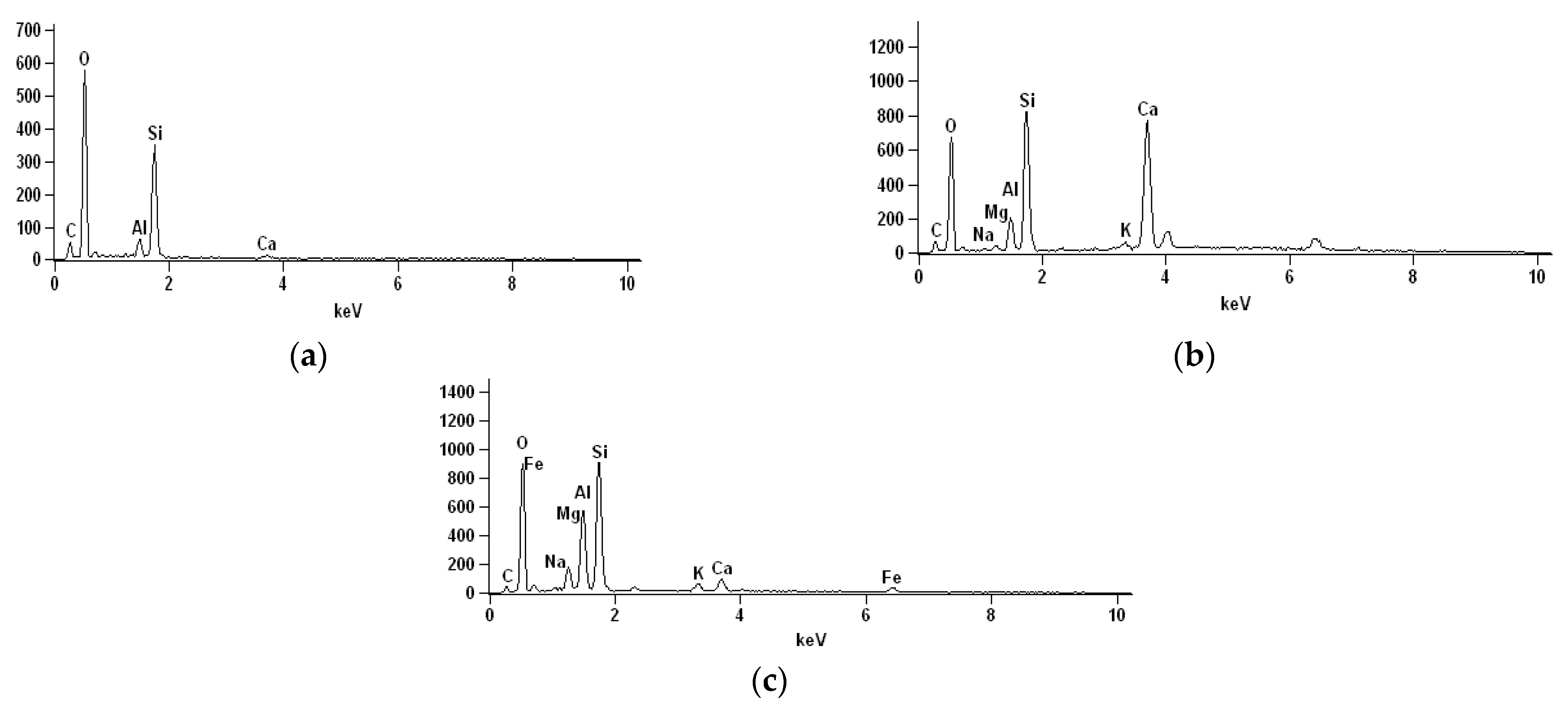
3.6. Microstructural Analysis

The microstructural evaluation by scanning electron microscopy (SEM) provided key insights into the internal morphology and hydration products of the soil–cement composites. Figure 10 displays representative SEM images of samples SF, G10, and G40. The relevant features are highlighted in the Figure: orange rectangles indicate C-S-H-rich regions with dense morphology, red circles mark visible pores within the matrix, yellow circles show acicular ettringite crystals, burgundy rectangles denote large unreacted gypsum particles in the G40 formulation, and the yellow rectangle highlights more elongated ettringite crystals with characteristic acicular morphology. These features are consistent with the morphological differences described in the subsequent paragraphs and help illustrate the relationship between gypsum content, microstructure, and material performance.
The SF sample exhibited a relatively compact matrix with a moderate presence of C-S-H (calcium silicate hydrate) phases and limited porosity. The absence of significant ettringite formation is consistent with the lower sulfate availability in this formulation. This microstructural pattern correlates with the intermediate mechanical strength and low water absorption observed in this sample.
In contrast, the G10 sample displayed a denser and more cohesive matrix with enhanced particle bonding. Needle-like ettringite crystals were observed dispersed throughout the structure, filling microvoids and contributing to a refined pore network. These features support the higher compressive strength and reduced water absorption of G10. The coexistence of ettringite and C-S-H appears to enhance matrix integrity and is indicative of an optimal balance between early hydration reactions and long-term stability. Similar findings have been reported in the literature [76,77], emphasizing the synergistic effect of moderate gypsum incorporation in promoting early ettringite formation without compromising the long-term stability of the cementitious matrix.
The G40 sample, however, exhibited microstructural degradation. SEM analysis revealed large unreacted gypsum agglomerates, significant porosity, and microcracks—particularly in regions of ettringite accumulation. These features are associated with internal stress from excessive ettringite formation and lower matrix cohesion. The porous structure explains the reduced mechanical strength and increased water absorption seen in this formulation. Similar mechanisms have been reported in high-sulfate cementitious systems, where overproduction of ettringite contributes to expansion, cracking, and durability loss [78,79].
The EDS analysis (Figure 11) further supported the SEM findings. For G10, the EDS spectra showed clear peaks for calcium (Ca), silicon (Si), and aluminum (Al), consistent with the formation of C-S-H and C-A-S-H phases—essential for mechanical performance and durability. Conversely, the EDS spectrum for G40 revealed a more heterogeneous elemental distribution, with visible concentrations of unreacted gypsum and lower levels of hydration products. The irregular distribution of elements such as iron (Fe), aluminum (Al), silicon (Si), magnesium (Mg), and sodium (Na) suggests the presence of residual soil minerals and incomplete hydration, particularly in G40.
Furthermore, the presence of free quartz, as evidenced by the high SiO2/Al2O3 molar ratio (ranging from 8.66 to 10.53, based on XRD), may act as an inert phase that creates discontinuity zones within the matrix, promoting pore formation and increasing water absorption. These effects are especially apparent in G40 and contribute to its inferior performance.
The absence of portlandite (Ca(OH)2) in the XRD patterns further supports the hypothesis that this phase was consumed in pozzolanic reactions or transformed into calcite (CaCO3) via carbonation. This is corroborated by the presence of calcite peaks in the XRD patterns and carbonate bands in the FTIR spectra (Section 3.7). It is also possible that portlandite exists in an amorphous or poorly crystalline state, escaping detection by XRD.
A methodological limitation should be noted regarding the EDS analysis. Since the spectra were acquired from fracture surfaces, the data may be affected by surface roughness and uneven morphology, which can limit spatial resolution and compositional accuracy. While the results provide useful qualitative insights, future studies should consider using polished cross-sections to improve the reliability of hydration product identification.

3.7. FTIR Analysis

FTIR analysis was performed to investigate the functional groups and chemical bonds present in the composites and to complement the microstructural findings. Figure 12 shows the FTIR spectra for the standard formulation (SF) and for samples with 10% (G10) and 40% (G40) gypsum replacement. In the 3600–3000 cm−1 region, SF displayed a narrow band at ~3640 cm−1 corresponding to the O–H stretching of portlandite (Ca(OH)2), which was less intense or absent in G10 and G40, suggesting consumption through pozzolanic or carbonation reactions. A broad band near 3450 cm−1, attributed to O–H stretching in C–S–H and adsorbed water, was more prominent in G10 and G40, indicating a higher degree of hydration and water retention [46,80]. The band near 1650 cm−1, more visible in G10 and G40, is related to H–O–H bending vibrations of retained molecular water. Between 1550 and 1250 cm−1, all samples exhibited carbonate (C–O) bands, with higher intensity in G10 and G40, consistent with partial carbonation and supported by calcite peaks in XRD. These observations confirm the transformation of portlandite into calcite and the presence of carbonation products. In the region between 1150 and 900 cm−1, sulfate groups (SO42−) and Si–O–Si vibrations overlapped. The sulfate bands were stronger in gypsum-containing samples, particularly G10, suggesting ettringite formation. Slightly lower intensity in G40 may reflect reduced hydration efficiency or overlapping effects of unreacted gypsum. Finally, the 900–700 cm−1 region showed Al–O and Si–O bending modes from clay minerals (e.g., illite) and aluminosilicate hydrates (C–A–S–H) [45,81]. These bands were present in all spectra, but weaker in G40, suggesting lower formation of hydration products and a greater proportion of unreacted or inert phases, as also observed in SEM and XRD analyses
Overall, the FTIR spectra reinforce the findings from XRD and SEM/EDS. Moderate gypsum content (G10) favors the formation of cementitious phases and carbonation products associated with improved performance, while excessive gypsum (G40) appears to reduce hydration efficiency and promote porosity.

3.8. Environmental Implications and Limitations Related to Gypsum Impurities

The use of recycled gypsum waste as a partial substitute for Portland cement in soil–cement bricks represents an environmentally favorable strategy. It contributes to reducing CO2 emissions, energy consumption, and landfill disposal associated with construction and demolition waste. The production of 1 kg of Portland cement emits approximately 0.9 kg of CO2 [82], primarily due to the calcination of limestone and the high energy demands of clinker production [83,84]. With 10% cement replacement and an average of 0.3 kg of cement per brick, the use of recycled gypsum in 75 bricks would avoid the emission of approximately 20.25 kg of CO2, highlighting its environmental benefit at scale. The processing of recycled gypsum involves only low-energy steps, drying, grinding, and sieving, making it a more sustainable alternative compared to cement production. In line with successful examples from other sectors, such as mining and metallurgy, that demonstrate that circular economy models can be enhanced by integrating waste materials into cement-based systems through institutional synergy and localized circular flows [85], the reuse of recycled gypsum supports circular economy goals by promoting waste valorization and resource efficiency.
However, an important methodological limitation of this study must be acknowledged: the chemical composition of the recycled gypsum waste was not fully characterized in terms of potential impurities. These impurities may include organic matter, soluble salts such as chlorides or sulfates, and heavy metals, which can significantly influence hydration kinetics, the formation of cementitious products, and the long-term performance and environmental safety of the bricks. While the gypsum used in this work was visually selected and thermally treated at 60 ± 5 °C to remove moisture, no chemical treatments or specific analyses were conducted to quantify impurity levels. The presence of these impurities may delay the setting time or cause premature stiffening depending on salt concentration, reduce mechanical strength by interfering with hydration reactions, compromise durability due to enhanced leaching or efflorescence, and pose environmental risks if contaminants migrate from the bricks during use or disposal. Given these concerns, future studies should include comprehensive chemical characterization of recycled gypsum from different sources, using techniques such as XRF, TGA, and leaching tests, to evaluate impurity content and assess its impact on strength, durability, and environmental compliance. Additionally, comparing untreated and purified gypsum could provide further insight into the necessity and feasibility of pre-treatment.
Despite this limitation, the formulations with 10% gypsum substitution showed adequate performance in mechanical, physical, and durability tests, suggesting that the impurity level in the material used was not critical. Further studies should be done to assess the long-term leaching and environmental impact of potential impurities in recycled gypsum.

4. Conclusions

This study demonstrated that replacing up to 20% of Portland cement with recycled gypsum waste in soil–cement bricks is technically feasible and environmentally advantageous. Replacing up to 20% of Portland cement with recycled gypsum waste in soil–cement bricks proved technically feasible and compliant with Brazilian standards, with the 10% gypsum formulation (G10) achieving the highest compressive strength after 28 days of curing. This result was supported by microstructural and mineralogical analyses, which indicated the formation of denser cementitious matrices rich in C-S-H and C-A-S-H phases.
Although water absorption increased slightly with higher gypsum contents, all values remained within acceptable limits. Durability was also maintained in formulations with up to 20% gypsum, while the 40% formulation (G40) showed signs of performance loss due to excessive ettringite formation and carbonation-related degradation.
Beyond technical validation, this approach contributes to sustainability goals by reducing cement consumption, diverting gypsum waste from landfills, and lowering carbon emissions. However, proportions above 20% should be avoided to preserve the mechanical and durability performance of the bricks.

Author Contributions

Conceptualization, E.S.S.N., H.A.d.O., Z.S.M. and C.P.d.S.; Methodology, E.S.S.N., H.A.d.O., M.d.A.G. and Z.S.M.; Software, E.S.S.N. and H.A.d.O.; Validation, E.S.S.N., C.P.d.S. and H.A.d.O.; Formal analysis, E.S.S.N.; Investigation, E.S.S.N., H.A.d.O. and M.d.A.G.; Resources, M.E.G.V., Z.S.M. and H.A.d.O.; Data curation, E.S.S.N., M.E.G.V. and Z.S.M.; Writing—original draft preparation, E.S.S.N.; Writing—review and editing, H.A.d.O., Z.S.M., C.P.d.S. and M.d.A.G.; Visualization, E.S.S.N., C.P.d.S., M.d.A.G., M.E.G.V. and Z.S.M.; Supervision, Z.S.M.; Project administration, H.A.d.O. and Z.S.M.; Funding acquisition, Z.S.M. All authors have read and agreed to the published version of the manuscript.

Funding

This research was funded by CNPq grant number 409048/2021-6.

Institutional Review Board Statement

Not applicable.

Informed Consent Statement

Not applicable.

Data Availability Statement

The data is available at: https://data.mendeley.com/datasets/75mm7y7h99/1, DOI: 10.17632/75mm7y7h99.1 Accessed on 1 April 2025.

Acknowledgments

The authors thank CAPES and CNPq for their financial support, and the Soil and Materials Laboratories (IFS), CMNano (UFS), and LMDCEM for providing infrastructure and technical assistance essential for this study.

Conflicts of Interest

The authors declare no conflict of interest.

References

  1. Mariyam, S.; Cochrane, L.; Al-Ansari, T.; McKay, G. A framework to support localized solid waste management decision making: Evidence from Qatar. Environ. Dev. 2024, 50, 100986. [Google Scholar] [CrossRef]
  2. Beccarello, M.; Di Foggia, G. Sustainable Development Goals data-driven local policy: Focus on SDG 11 and SDG 12. Adm. Sci. 2022, 12, 167. [Google Scholar] [CrossRef]
  3. Vilela, A.P.; Eugênio, T.M.C.; de Oliveira, F.F.; Mendes, J.F.; Ribeiro, A.G.C.; Vaz, L.E.V.d.S.B.; Mendes, R.F. Technological properties of soil-cement bricks produced with iron ore mining waste. Constr. Build. Mater. 2020, 262, 120883. [Google Scholar] [CrossRef]
  4. da Silva, M.V.V.; Garcia, R.L.M.; de Siqueira, R.A.; Júnior, G.A.d.S. Técnicas de estabilização e reforço sustentável do solo. Rev. FT 2024, 29, 29–30. [Google Scholar] [CrossRef]
  5. Xiong, W.; Chen, Y.; Xu, J.; Zhang, Z.; Liang, C. Reuse of engineering waste soil and recycled fine aggregate to manufacture eco-friendly unfired clay bricks: Experimental assessment, data-driven modeling and environmental friendliness evaluation. Case Stud. Constr. Mater. 2023, 19, e02608. [Google Scholar] [CrossRef]
  6. Hashim, A.A.; Anaee, R.A.; Nasr, M.S. Improving the mechanical, corrosion resistance, microstructural and environmental performance of recycled aggregate concrete using ceramic waste powder as an alternative to cement. Ceramics 2025, 8, 11. [Google Scholar] [CrossRef]
  7. Rocha Silva, B.; Junior, H.S.M.; Filho, A.J.d.S.; Santos, A.M.S.; de Melo, F.M.C.; Almeira, V.G.d.O.; de Oliveira, H.A. Soil cement brick production process: Literature review. MOJ Civ. Eng. 2023, 7, 19–26. [Google Scholar] [CrossRef]
  8. Ângelo, F.A.; Simões, G.F. Tijolos ecoeficientes de barro cru com resíduos sólidos e efluente industrial utilizando tecnologias não convencionais. Ambiente Construído 2023, 23, 131–148. [Google Scholar] [CrossRef]
  9. de Castro, E.D.; Villella, L.S.; Mendes, L.M.; Mendes, R.F.; Ribeiro, A.G.C.; Júnior, J.B.G.; Rabelo, G.F. Analysis of the coffee peel application over the soil-cement bricks properties. Coffee Sci. 2019, 14, 12. [Google Scholar] [CrossRef]
  10. Azevedo, A.R.G.; Marvila, T.; Fernandes, W.J.; Alexandre, J.; Xavier, G.; Zanelato, E.; Cerqueira, N.; Pedroti, L.; Mendes, B. Assessing the potential of sludge generated by the pulp and paper industry in assembling locking blocks. J. Build. Eng. 2019, 23, 334–340. [Google Scholar] [CrossRef]
  11. Araújo, V.D.; Martins, V.A.; Cavalheri, P.S.; Honório, L.; Lima, P.D.M.; Filho, F.J.C.M. Incorporation of tannery waste and sugarcane bagasse ash in soil–cement bricks. Rev. AIDIS De Ing. Y Cienc. Ambient. 2022, 15, 154. [Google Scholar] [CrossRef]
  12. Ahmed, A.; Ugai, K.; Kamei, T. Laboratory and field evaluations of recycled gypsum as a stabilizer agent in embankment construction. Soils Found. 2011, 51, 975–990. [Google Scholar] [CrossRef]
  13. Azevedo, A.C.; Delgado, J.M.P.Q.; Neves, T.H.C.; Costa e Silva, A.J. Adhesion of gypsum plaster coatings: Experimental evaluation. In Building Pathology and Rehabilitation; Springer: Berlin/Heidelberg, Germany, 2021; pp. 41–66. [Google Scholar] [CrossRef]
  14. Camarini, G.; Pimentel, L.L.; De Sá, N.H.R. Assessment of the material loss in walls renderings with β-hemihydrate paste. Appl. Mech. Mater. 2011, 71–78, 1242–1245. [Google Scholar] [CrossRef]
  15. Jiménez-Rivero, A.; García-Navarro, J. Exploring factors influencing post-consumer gypsum recycling and landfilling in the European Union. Resour. Conserv. Recycl. 2017, 116, 116–123. [Google Scholar] [CrossRef]
  16. Antunes, M.L.P.; de Sá, A.B.; Oliveira, P.S.; Rangel, E.C. Utilization of gypsum from construction and demolition waste in Portland cement mortar. Cerâmics 2019, 65 (Suppl. S1), 1–6. [Google Scholar] [CrossRef]
  17. Torres-Ortega, R.; Torres-Sanchez, D.L.; López-Lara, T. Mechanical properties of hydraulic concretes with partial replacement of Portland cement by pozzolans obtained from agro-industrial residues: A review. Heliyon 2024, 11, e41004. [Google Scholar] [CrossRef] [PubMed]
  18. Puerto, J.D.; Uribe, S.; Ayala, L.; Padilla, A.; Rodriguez, A. Reliability of reusing gypsum flat board grinded waste as a conventional plaster replacement for buildings. Sustainability 2024, 16, 7889. [Google Scholar] [CrossRef]
  19. ASTM D6913; Standard Test Methods for Particle-Size Distribution (Gradation) of Soils Using Sieve Analysis. ASTM International: West Conshohocken, PA, USA, 2017.
  20. ASTM D4318-18; Standard Test Methods for Liquid Limit, Plastic Limit, and Plasticity Index of Soils. ASTM International: West Conshohocken, PA, USA, 2018.
  21. DNER-ME 093/94; Solos—Determinação da Densidade Real. DNER: Rio de Janeiro, Brazil, 1994.
  22. Kang, H.; Kang, S.-H.; Moon, J. A comparative investigation of hydration reaction of Portland cement with the use of alkanolamine as a chemical admixture or grinding agent under laboratory condition. J. Build. Eng. 2024, 88, 109214. [Google Scholar] [CrossRef]
  23. Axthammer, D.; Lange, T.; Dengler, J.; Gädt, T. Early hydration and viscoelastic properties of tricalcium aluminate pastes influenced by soluble sodium salts. Cem. Concr. Res. 2025, 190, 107788. [Google Scholar] [CrossRef]
  24. NBR 10833; Fabricação de Tijolo e Bloco de Solo-Cimento com Utilização de Prensa Manual ou Hidráulica—Procedimento. ABNT: Rio de Janeiro, Brazil, 2012.
  25. ASTM C191; Standard Test Methods for Time of Setting of Hydraulic Cement by Vicat Needle. ASTM International: West Conshohocken, PA, USA, 2023.
  26. ASTM C188; Standard Test Method for Density of Hydraulic Cement. ASTM International: West Conshohocken, PA, USA, 2022.
  27. NBR 16372; 2015—Cimento Portland e Outros Materiais em pó—Determinação da Finura pelo Método de Permeabilidade ao ar (Método de Blaine). ABNT: Rio de Janeiro, Brazil, 2015.
  28. ASTM C109/C109M; Standard Test Method for Compressive Strength of Hydraulic Cement Mortars. ASTM International: West Conshohocken, PA, USA, 2023.
  29. Santa Rosa, J.M.S.; Silva, R.G.P.; Lafayette, K.P.V. Sustainable Alternative for the Production of Soil Cement Bricks. J. Manag. Sustain. 2023, 13, 45. [Google Scholar] [CrossRef]
  30. Ashour, T.; Korjenic, A.; Korjenic, S. Equilibrium Moisture Content of Earth Bricks Biocomposites Stabilized with Cement and Gypsum. Cem. Concr. Compos. 2015, 59, 18–25. [Google Scholar] [CrossRef]
  31. Metzker, S.L.O.; Sabino, T.P.F.; Mendes, J.F.; Ribeiro, A.G.C.; Mendes, R.F. Soil-cement bricks development using polymeric waste. Environ. Sci. Pollut. Res. 2022, 29, 21034–21048. [Google Scholar] [CrossRef] [PubMed]
  32. Kongkajun, N.; Laitila, E.A.; Ineure, P.; Prakaypan, W.; Cherdhirunkorn, B.; Chakartnarodom, P. Soil-Cement Bricks Produced from Local Clay Brick Waste and Soft Sludge from Fiber Cement Production. Case Stud. Constr. Mater. 2020, 13, e00448. [Google Scholar] [CrossRef]
  33. Leonel, R.F.; Folgueras, M.V.; Dalla Valentina, L.V.O.; Prim, S.R.; Prates, G.A.; Caraschi, J.C. Characterization of Soil-Cement Bricks with Incorporation of Used Foundry Sand. Cerâmica 2017, 63, 329–335. [Google Scholar] [CrossRef]
  34. NBR 8492; Tijolo de Solo-Cimento—Análise Dimensional, Determinação da Resistência à Compressão e da Absorção de Água—Método de Ensaio. ABNT: Rio de Janeiro, Brazil, 2012.
  35. NBR 5739; Cimento Portland—Determinação da Resistência à Compressão. ABNT: Rio de Janeiro, Brazil, 2007.
  36. NBR 10836; Bloco de Solo-Cimento Sem Função Estrutural—Análise Dimensional, Determinação da Resistência à Compressão e da Absorção de Água—Método de Ensaio. ABNT: Rio de Janeiro, Brazil, 2012.
  37. NBR 13554; 2012—Solo-Cimento—Ensaio de Durabilidade por Molhagem e Secagem—Método de Ensaio. ABNT: Rio de Janeiro, Brazil, 2012.
  38. Hammer, Ø. Harper, D.A.T.; Ryan, P.D. PAST: Paleontological Statistics software package for education and data analysis. Palaeontol Electron. 2001, 4, 1–9. Available online: http://palaeo-electronica.org/2001_1/past/issue1_01.htm (accessed on 27 June 2025).
  39. Chernyshova, I.V.; Lesovik, V.S.; Fediuk, R.S.; Amran, M.; Vatin, N.I. Enhancement of Fresh Properties and Performances of the Eco-Friendly Gypsum-Cement Composite (EGCC). Constr. Build. Mater. 2020, 260, 120462. [Google Scholar] [CrossRef]
  40. Alves, M.L.X.F.N.; Barros, S.V.A.; de Oliveira, F.N. Physical and Chemical Characterization of Soil for Use in Ecological Bricks. In Uniting Knowledge: Integrated Scientific Research for Global Development; Seven Publicações: São José dos Pinhais, Brazil, 2024; Volume 2, pp. 532–539. [Google Scholar] [CrossRef]
  41. Qi, J.; Ma, W.; Song, C. Influence of Freeze—Thaw on Engineering Properties of a Silty Soil. Cold Reg. Sci. Technol. 2008, 53, 397–404. [Google Scholar] [CrossRef]
  42. Melnick, V.; Pianaro, S.A.; Cava, S.; Tebcherani, S.M. Application of Oil Shale Mining By-Products as Raw Materials in the Determination of the Vitrification Curve of Red Porcelain Stoneware Tiles by Dilatometric Method. Appl. Clay Sci. 2010, 50, 311–314. [Google Scholar] [CrossRef]
  43. Peffers, K.; Tuunanen, T.; Rothenberger, M.A.; Chatterjee, S. A Design Science Research Methodology for Information Systems Research. In Design Science Research: A Method for Science and Engineering; Peffers, K., Rothenberger, M.A., Kuechler, B., Eds.; CRC Press: Boca Raton, FL, USA, 2023; pp. 11–28. [Google Scholar] [CrossRef]
  44. Harrison, T.; Jones, M.R.; Lawrence, D. The Production of Low Energy Cements. In Lea’s Chemistry of Cement and Concrete, 5th ed.; Hewlett, P.C., Liska, M., Eds.; Butterworth-Heinemann: Oxford, UK, 2019; pp. 341–361. [Google Scholar] [CrossRef]
  45. Reigl, S.; Van Driessche, A.E.S.; Wagner, E.; Montes-Hernandez, G.; Mehringer, J.; Koltzenburg, S.; Kunz, W.; Kellermeier, M. Toward More Sustainable Hydraulic Binders: Controlling Calcium Sulfate Phase Selection via Specific Additives. ACS Sustain. Chem. Eng. 2023, 11, 8450–8461. [Google Scholar] [CrossRef]
  46. Stawski, T.M.; Besselink, R.; Chatzipanagis, K.; Hövelmann, J.; Benning, L.G.; Van Driessche, A.E.S. Nucleation Pathway of Calcium Sulfate Hemihydrate (Bassanite) from Solution: Implications for Calcium Sulfates on Mars. J. Phys. Chem. C 2020, 124, 8411–8422. [Google Scholar] [CrossRef]
  47. Gitirana, G.F.N.; Bandeira, A.P.N.; Dourado, K.C.A.; Souza Neto, J.B. Solos Não Saturados no Contexto Geotécnico, 2nd ed.; Editora Cubo: São Carlos, Brazil, 2023. [Google Scholar] [CrossRef]
  48. Macioski, G.; Soto, N.T.A.; Medeiros, M.H.F.d.; Hoppe Filho, J.; Araújo, M.S.d.; Cerri, J.A. Portlandite consumption by red ceramic waste due to alkali activation reaction. Ambiente Construído 2021, 21, 7–21. [Google Scholar] [CrossRef]
  49. Kleib, J.; Amar, M.; Aouad, G.; Bourbon, X.; Benzerzour, M.; Abriak, N.-E. The use of Callovo-Oxfordian Argillite as a raw material for Portland cement clinker production. Buildings 2022, 12, 1421. [Google Scholar] [CrossRef]
  50. Bošnjak, J.; Ožbolt, J.; Hahn, R. Permeability Measurement on High Strength Concrete without and with Polypropylene Fibers at Elevated Temperatures Using a New Test Setup. Cem. Concr. Res. 2013, 53, 104–111. [Google Scholar] [CrossRef]
  51. Park, S.-S.; Suh, E.-H.; Chae, K.-H.; Jang, S.-K.; Kim, J.-H. A Study on Soil Cementation and Calcite Precipitation with Clay as a Medium. J. Korean Geotech. Soc. 2015, 31, 17–27. [Google Scholar] [CrossRef]
  52. Krause, F.; Renner, B.; Coppens, F.; Dewanckele, J.; Schwotzer, M. Reactivity of gypsum-based materials subjected to thermal load: Investigation of reaction mechanisms. Materials 2020, 13, 1427. [Google Scholar] [CrossRef]
  53. Azimi, G.; Papangelakis, V.G. Mechanism and kinetics of gypsum–anhydrite transformation in aqueous electrolyte solutions. Hydrometallurgy 2011, 108, 122–129. [Google Scholar] [CrossRef]
  54. Voigt, W.; Freyer, D. Solubility of anhydrite and gypsum at temperatures below 100 °C and the gypsum-anhydrite transition temperature in aqueous solutions: A re-assessment. Front. Nucl. Eng. 2023, 2, 1208582. [Google Scholar] [CrossRef]
  55. Al Disi, Z.A.; Sadooni, F.; Al-Kuwari, H.A.-S.; Bontognali, T.R. Microbially influenced formation of anhydrite at low temperature. Sci. Total Environ. 2023, 902, 165820. [Google Scholar] [CrossRef]
  56. Engbrecht, D.C.; Hirschfeld, D.A. Thermal analysis of calcium sulfate dihydrate sources used to manufacture gypsum wallboard. Thermochim. Acta 2016, 639, 173–185. [Google Scholar] [CrossRef]
  57. Lira, M.C.d.A.; Neiva, L.S. Investigative study of the potentialities of noble applications for the Brazilian calcium sulfate α-hemihydrate. Pesqui. E Ensino Em Ciências Exatas E Da Nat. 2020, 4, e1516. [Google Scholar] [CrossRef]
  58. Vipulanandan, C.; Mohammed, A. XRD and TGA, swelling and compacted properties of polymer treated sulfate contaminated CL soil. J. Test. Eval. 2016, 44, 2270–2284. [Google Scholar] [CrossRef]
  59. Cai, H.; Chen, C.; Wei, S.; Zhu, S. Strength development of cemented soil cured in water-air conditions at varied temperatures: Experimental investigation and model characterization. J. Mater. Civ. Eng. 2023, 35, 3. [Google Scholar] [CrossRef]
  60. Zak, P.; Ashour, T.; Korjenic, A.; Korjenic, S.; Wu, W. The influence of natural reinforcement fibers, gypsum and cement on compressive strength of earth bricks materials. Constr. Build. Mater. 2016, 106, 179–188. [Google Scholar] [CrossRef]
  61. Zhu, Y.; Jia, Y.; Xie, X.S.; Xu, J. Study on the Macroscopic Properties and Microstructure of High Fly Ash Content Alkali-Activated Fly Ash Slag Concrete Cured at Room Temperature. Materials 2025, 18, 547. [Google Scholar] [CrossRef] [PubMed]
  62. Rohman, M.N.; Simanihuruk, B.; Dewita, H. Karakteristik Beton Mutu FC 30 Dengan Menggunakan Limbah Peleburan Baja (Slag) Dan Pembakaran Batubara (Fly Ash). Pros. Semin. Nas. Rekayasa Dan Teknol. 2025, 5, 61–65. [Google Scholar] [CrossRef]
  63. Kirgiz, M.S.; Khatib, J.; Galdino, A.G.S.; Kenaï, S.; Ashteyat, A.M.; Campilho, R.D.S.G.; González-Lezcano, R.A.; Bamigboye, G.; Nagaprasad, N.; Ramaswamy, K. Waste Marble Sludge and Calcined Clay Brick Powders in Conventional Cement Farina Production for Cleaner Built Environment. Dent. Sci. Rep. 2025, 15, 3467. [Google Scholar] [CrossRef]
  64. Li, Y.; Yan, X.; Wan, M.P.; Zhou, J.; Liu, J. Research on Recycling and Utilization of Shredded Waste Mask Fibers to Prepare Sustainable Engineered Cementitious Composites. Buildings 2025, 15, 402. [Google Scholar] [CrossRef]
  65. Jafari, M.M.; Bagheripour, M.H.; Yaghoubi, E. Prediction of Strength Properties of Reinforced and Stabilized Sandy Soil as a Building Foundation Material. Buildings 2025, 15, 382. [Google Scholar] [CrossRef]
  66. NBR 10834; 2012—Bloco de Solo-Cimento Sem Função Estrutural—Requisitos. ABNT: Rio de Janeiro, Brazil, 2012.
  67. Dulal, P.; Maharjan, S.; Timalsina, M.P.; Maharjan, Y.; Giri, A.; Tamang, A. Engineering properties of cement-stabilized compressed earth bricks. J. Build. Eng. 2023, 77, 107453. [Google Scholar] [CrossRef]
  68. Thennarasan Latha, A.; Murugesan, B.; Thomas, B.S. Compressed stabilized earth block incorporating municipal solid waste incinerator bottom ash as a partial replacement for fine aggregates. Buildings 2023, 13, 1114. [Google Scholar] [CrossRef]
  69. Corrêa-Silva, M.; Cristelo, N.; Rouainia, M.; Araújo, N.; Miranda, T. Constitutive behaviour of a clay stabilised with alkali-activated cement based on blast furnace slag. Sustainability 2022, 14, 13736. [Google Scholar] [CrossRef]
  70. Kamran, F.; Basavarajappa, M.; Bala, N.; Hashemian, L. Laboratory Evaluation of Stabilized Base Course Using Asphalt Emulsion and Asphaltenes Derived from Alberta Oil Sands. Constr. Build. Mater. 2021, 283, 122735. [Google Scholar] [CrossRef]
  71. Dong, W.; Li, W.; Tao, Z.; Wang, K. Piezoresistive Properties of Cement-Based Sensors: Review and Perspective. Constr. Build. Mater. 2019, 203, 146–163. [Google Scholar] [CrossRef]
  72. Chen, H.; Zhou, S.; Zhang, J.; Liu, X.; Wu, H. Effect of fly ash and gypsum on drying shrinkage and mechanical properties of one-part alkali-activated slag mortar. Struct. Concr. 2025, 26, 1275–1288. [Google Scholar] [CrossRef]
  73. NBR 13553; Materiais Para Emprego em Parede Monolítica de Solo-Cimento Sem Função estrutural—Requisitos. ABNT: Rio de Janeiro, Brasil, 2012.
  74. Höglund, L.O. Some notes of ettringite formation in cementitious materials; Influence of hydration and thermodynamic constraints for durability. Cem. Concr. Res. 1992, 22, 217–228. [Google Scholar] [CrossRef]
  75. Gu, Y.; Martin, R.-P.; Metalssi, O.O.; Fen-Chong, T.; Dangla, P. Pore size analyses of cement paste exposed to external sulfate attack and delayed ettringite formation. Cem. Concr. Res. 2019, 123, 105766. [Google Scholar] [CrossRef]
  76. Wang, L.; Wang, Q.; Cai, J.; Zhou, F.; Cheng, Z.; Zhang, J. Experimental Study on the Mechanical Properties and Microstructural Mechanisms of Coal Gangue-Based Cementitious Materials Synergistically Activated by Desulfurization Gypsum and Lime. Polymers 2025, 17, 932. [Google Scholar] [CrossRef] [PubMed]
  77. Shi, C.; Zhang, Z.; Yang, J.; Zhang, J. An Eco-Friendly Phosphogypsum-Based Cementitious Material. Front. Phys. 2022, 10, 892037. [Google Scholar] [CrossRef]
  78. Fu, Y.; Beaudoin, J.J. Mechanisms of Delayed Ettringite Formation in Portland Cement Systems. ACI Mater. J. 1996, 93, 327–333. [Google Scholar] [CrossRef]
  79. Li, L.; Darquennes, A.; Hannawi, K.; Che, C. Effects of Sulfates on the Hydration of Portland Cement—A Review. Constr. Build. Mater. 2021, 270, 121134. [Google Scholar] [CrossRef]
  80. Taman, M.; Abd Elaty, M.A.; Behiry, R.N. Codes Applicability of Estimating the FRC Compressive Strength by the Core-Drilling Method. Constr. Build. Mater. 2022, 330, 127227. [Google Scholar] [CrossRef]
  81. Wild, S.; Khatib, J.M. Portlandite consumption in metakaolin cement pastes and mortars. Cem. Concr. Res. 1997, 27, 137–146. [Google Scholar] [CrossRef]
  82. Habert, G.; d’Espinose de Lacaillerie, J.B.; Roussel, N. An environmental evaluation of geopolymer based concrete production: Reviewing current research trends. J. Clean. Prod. 2010, 19, 1229–1238. [Google Scholar] [CrossRef]
  83. Scrivener, K.L.; John, V.M.; Gartner, E.M. Eco-efficient cements: Potential economically viable solutions for a low-CO2 cement-based materials industry. Cem. Concr. Res. 2018, 114, 2–26. [Google Scholar] [CrossRef]
  84. Habert, G. Environmental Impact of Portland Cement Production. In Eco-Efficient Concrete; Woodhead Publishing Series in Civil and Structural Engineering; Woodhead Publishing: Cambridge, UK, 2013; pp. 3–25. [Google Scholar] [CrossRef]
  85. Born, K. Exploring the Spatial Dynamics of Circular Economy Transitions: Insights and Lessons from Chile’s Mining Territories. Prog. Econ. Geogr. 2025, 3, 100041. [Google Scholar] [CrossRef]
Figure 1. Compressive strength of formulations containing 10% cement and varying sand content (0% to 40% by total mass), used as a partial replacement for soil. The optimal performance was achieved with 10% sand, indicating a balance between workability and particle packing.
Ceramics 08 00083 g001
Figure 2. X-ray diffraction (XRD) patterns of soil, cement, and gypsum, highlighting the dominant crystalline phases and their compatibility for hydration reactions.
Ceramics 08 00083 g002
Figure 3. X-ray diffraction patterns of the soil–cement formulations with varying recycled gypsum content. The diffractograms reveal the presence of crystalline phases such as ettringite, gypsum, quartz, calcite, illite, paragonite, and inesite. The increased intensity of ettringite peaks in the samples with gypsum highlights the influence of sulfate addition on phase formation and potential effects on the material’s performance.
Ceramics 08 00083 g003
Figure 4. Particle size distribution: (a) for the soil–cement brick components according to ASTM D6913/D6913M, with dashed lines provided as a guide to the eye; (b) histogram showing the proportion of fine and coarse fractions contributing to compaction and mechanical behavior.
Ceramics 08 00083 g004aCeramics 08 00083 g004b
Figure 5. TG/DTG curves of gypsum. Mass loss events in the range of 100–200 °C are associated with dehydration of gypsum phases. A secondary peak near 560 °C suggests decomposition of minor components.
Ceramics 08 00083 g005
Figure 6. TG/DTG analysis of soil showing thermal events attributed to moisture loss and dehydroxylation of clay minerals, relevant for understanding reactivity and processing behavior.
Ceramics 08 00083 g006
Figure 7. Compressive strength at 7 and 28 days for each formulation. Bars represent standard deviation from five specimens. No intermediate age was tested. All formulations exceeded the 2 MPa minimum required, but the 10% gypsum formulation showed improved strength, while 40% gypsum reduced mechanical performance.
Ceramics 08 00083 g007
Figure 8. Water absorption of specimens after 7 days of curing. Results indicate increasing porosity with higher gypsum content, though all remain within acceptable standards.
Ceramics 08 00083 g008
Figure 9. Durability of bricks evaluated by mass loss after six wetting–drying cycles. Only the 40% gypsum formulation exceeded the acceptable threshold.
Ceramics 08 00083 g009
Figure 10. Scanning electron microscopy (SEM) images of (a) standard formulation (SF), (b) sample with 10 wt% gypsum (G10), and (c) sample with 40 wt% gypsum (G40), taken at 1500× and 3000× magnification. Scale bars represent 10 µm and 5 µm, respectively. Highlighted features include: orange rectangles indicating dense calcium silicate hydrate (C–S–H) regions, red circles marking visible pores, yellow circles denoting acicular ettringite crystals, burgundy rectangles identifying unreacted gypsum agglomerates in G40, and a yellow rectangle showing elongated ettringite with typical needle-like morphology. The SF sample presents a compact matrix with low porosity; G10 shows a denser structure with well-dispersed ettringite; G40 exhibits high porosity, microcracking, and unreacted gypsum, reflecting reduced microstructural integrity.
Ceramics 08 00083 g010
Figure 11. EDS spectra of the fracture surface of soil–cement specimens cured for 28 days: (a) SF; (b) G10; (c) G40. Spectra confirm the presence of calcium, silicon, aluminum, and sulfur, supporting the formation of C-S-H and ettringite, with variations correlating to gypsum content.
Ceramics 08 00083 g011
Figure 12. FTIR spectra of soil–cement composites with 0% (SF), 10% (G10), and 40% (G40) gypsum. Key bands include O–H, H–O–H, carbonate (C–O), sulfate (SO42−), and silicate (Si–O–Si) vibrations, indicating hydration and carbonation processes.
Ceramics 08 00083 g012
Table 1. Formulations used in the experiments (% by mass).
CompositionsSoilCementSandGypsum
SF801010-
G5809.5100.5
G10809101
G20808102
G40806104
Table 2. Specific density, bulk density, and specific surface area of raw materials used in soil–cement–gypsum formulations.
Specific Density (g/cm3)Bulk Density (g/cm3)Specific Surface Area (cm2/g)
Soil2.71 ± 0.021.15 ± 0.014243 ± 100
Gypsum2.25 ± 0.021.10 ± 0.025500 ± 150
Cement3.10 ± 0.021.40 ± 0.024400 ± 120
Sand2.63 ± 0.011.65 ± 0.01-
Table 3. Chemical composition of the raw materials determined by energy-dispersive X-ray fluorescence (EDXRF). Oxide content values are expressed in weight percentage, with an uncertainty of ±0.02 wt%.
ComponentSoilCementSandGypsum
CaO22.9780.951.5468.01
SiO239.398.4689.790.63
Fe2O318.455.951.721-
SO30.112.060.3229.97
K2O6.951.600.660.30
Al2O39.40-1.82-
TiO22.090.373.56-
Loss on ignition0.640.610.591.09
Table 4. Proportions of the phases identified by XRD using the Match! software.
Mineral PhaseConcentration Range (%)
Quartz24.7–38.0
Paragonite18.4–22.8
Inesite10.1–15.8
Ettringite8.0–10.0
Calcite12.5–16.2
Gypsum0.9–2.5
Ilite16.9–20.1
Disclaimer/Publisher’s Note: The statements, opinions and data contained in all publications are solely those of the individual author(s) and contributor(s) and not of MDPI and/or the editor(s). MDPI and/or the editor(s) disclaim responsibility for any injury to people or property resulting from any ideas, methods, instructions or products referred to in the content.

