Article

ZrB2 Gear Fabrication by Spark Plasma Sintering Coupled to Interface 3D Printing

by
Charles Manière
1,* and
Claude Estournès
2
1
Université de Caen Normandie, CRISMAT, Normandie University, ENSICAEN, CNRS, 14000 Caen, France
2
CIRIMAT, Université de Toulouse, Toulouse INP, CNRS, 118 Route de Narbonne, CEDEX 9, 31062 Toulouse, France
*
Author to whom correspondence should be addressed.
Ceramics 2025, 8(3), 81; https://doi.org/10.3390/ceramics8030081
Submission received: 24 May 2025 / Revised: 12 June 2025 / Accepted: 26 June 2025 / Published: 28 June 2025
(This article belongs to the Special Issue Ceramic Materials for Industrial Decarbonization)

Abstract

The production of ultra-high-temperature ceramic parts, like ZrB2, is very challenging, as they cannot be conventionally sintered without using significant amounts of additives, which reduce their high-temperature properties. However, it is possible to sinter these ceramics using spark plasma sintering (SPS) without additives or with minimal amounts. The challenge, then, lies in obtaining complex shapes. In this work, we report a solution for the fabrication of ZrB2 gears through the use of PLA-printed interfaces and graphite powder. This process is relatively simple and utilizes a fused deposition modeling (FDM) printer. The pros and cons of this approach are discussed with the aim of identifying what shapes can be produced using this method.

1. Introduction

Ultra-high temperature ceramics (UHTCs), or ultrarefractory materials, are strongly bonded ceramics with high mechanical strength and melting points above 3000 °C. These materials are the best candidates for routine use in high-temperature environments. They are widely used in space exploration, aeronautics, defense, energy, and other fields [1,2,3,4,5,6,7,8]. However, the main issue lies in the sintering of these materials, as their strong chemical bonds make pressureless sintering very difficult. The use of additives or applied pressure is generally required to reduce the sintering temperature and achieve full densification. Regarding additives, various approaches exist, but they typically involve materials with lower melting points, such as Ti64 [9] for metal, or B4C, MoSi2 for ceramics in amounts ranging from a few percent to 15% [6,10,11,12,13,14]. For certain ceramics that decompose at high temperatures, such as silicon nitride, various oxides, like magnesia, yttrium oxide, and alumina are mixed to form a eutectic, enabling liquid phase sintering at temperatures below 2000 °C [15,16,17,18,19,20]. The same method can be applied to silicon carbide; however, this ceramic can also be sintered with the addition of boron carbide at 2200 °C, resulting in much better microstructures [21,22,23,24]. The same approach can be applied to UHTCs like ZrB2, with carbon addition playing a crucial role in eliminating residual oxide phases [10,12,13]. Fully dense ceramics can be obtained, but even small amounts of carbon and boron carbide phases limit their high-temperature applications. To fully exploit the high-temperature properties of UHTCs, the best solution is to sinter these ceramics without additives. This can be achieved using spark plasma sintering (SPS) under 20–50 MPa at high temperatures approaching 2000 °C [14]. Since this approach is not pressureless, the new challenge becomes the fabrication of real parts with complex shapes. Various approaches can be employed to achieve the fabrication of complex shapes using SPS [25,26,27]. The first one involves the use of a multiple-punches configuration [28,29,30,31]. This approach is inspired by powder metallurgy [32,33] and utilizes the motion of different punches to control the densification of various powder zones. However, it is limited to shapes with discontinuous thickness. For such cases, we developed an interface-based approach called “DEFORMINT” [25,34,35,36], which allows the fabrication of complex shapes using embedded inert interfaces. One significant advantage of this approach is the ability to 3D print the interface, making the method much easier to implement [37]. This approach is well mastered for metals [38,39]. For ceramics, this method is more challenging for two reasons. First, the sintering shrinkage, which is about 30% for metals, increases to approximately 50% for ceramic powders. Second, higher sintering temperatures require the identification of an interface material that does not sinter or diffuse into the ceramic. In the case of ultra-refractories, like ZrB2, which have sintering temperatures approaching 2000 °C, selecting the appropriate interface material is difficult, as most ceramics will sinter at these high temperatures. The best choice appears to be graphite, which is the same material used for the tooling itself [36]. Since graphite is used as an additive to sinter ZrB2 [10], it must be present in excess or in a thick enough interface to ensure the ejection of the shape after sintering.
In this article, we present a solution that involves the use of PLA-printed interfaces to fabricate ZrB2 gears. Different configurations and sintering conditions are tested.

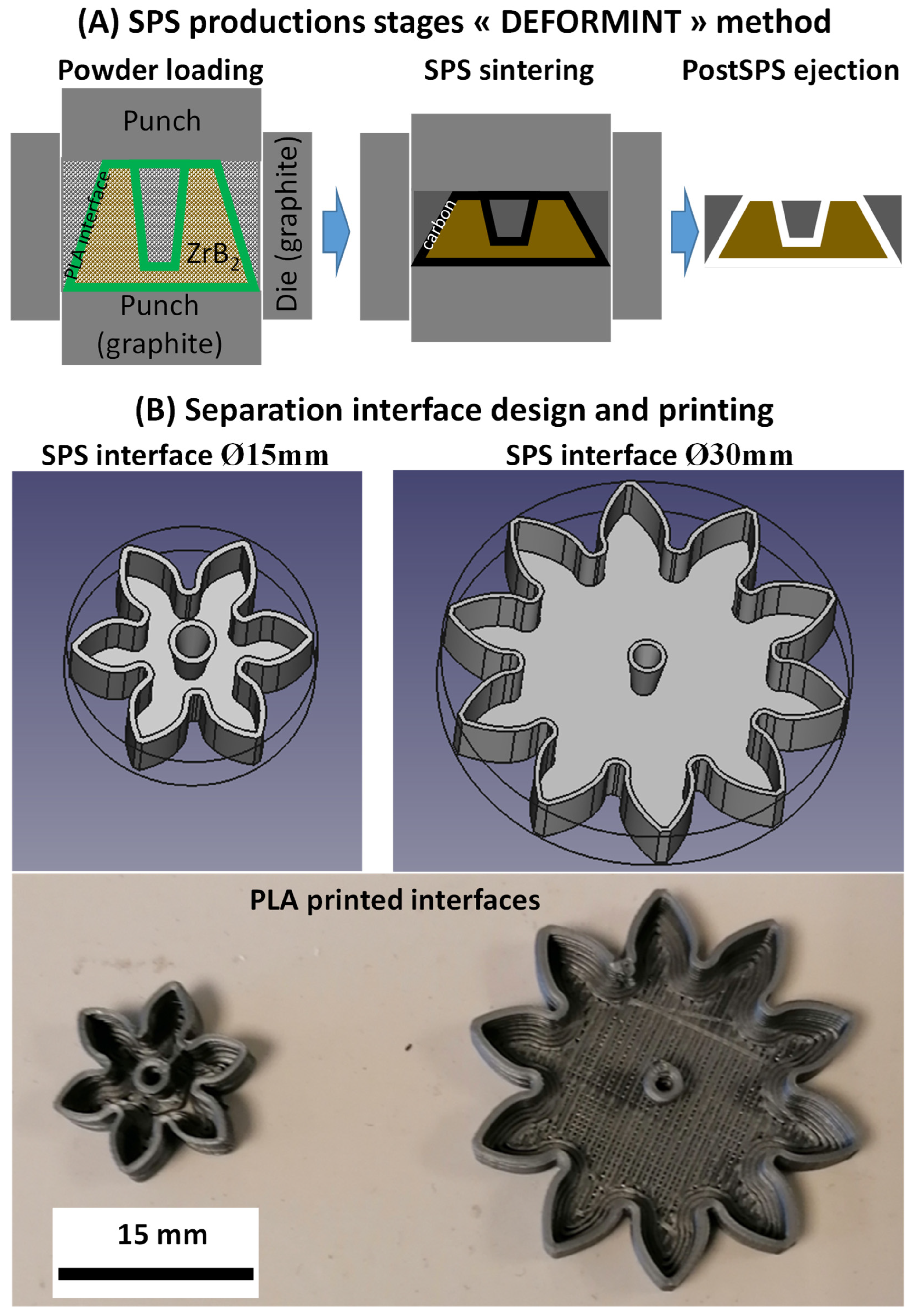
2. Materials and Methods
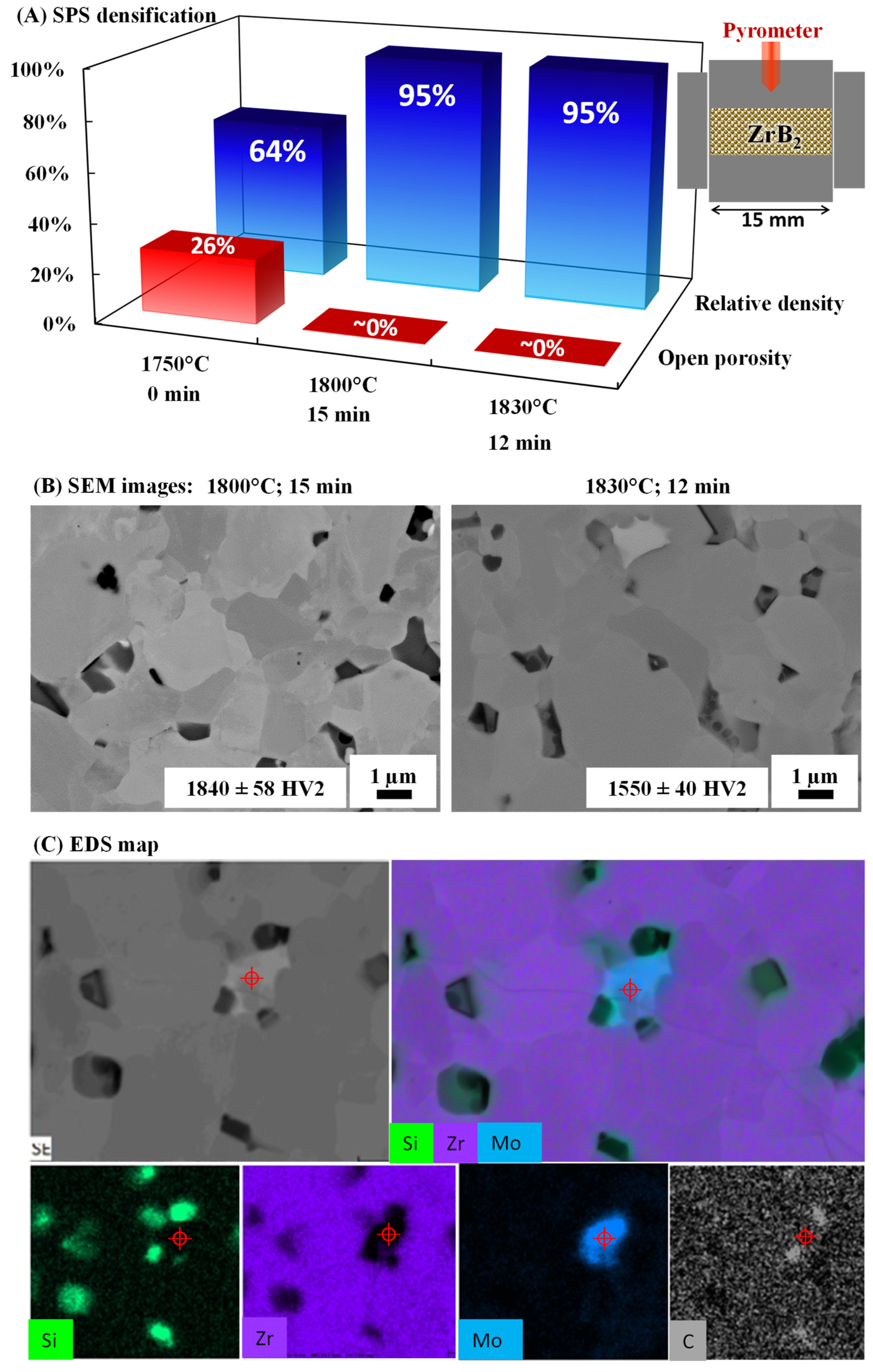
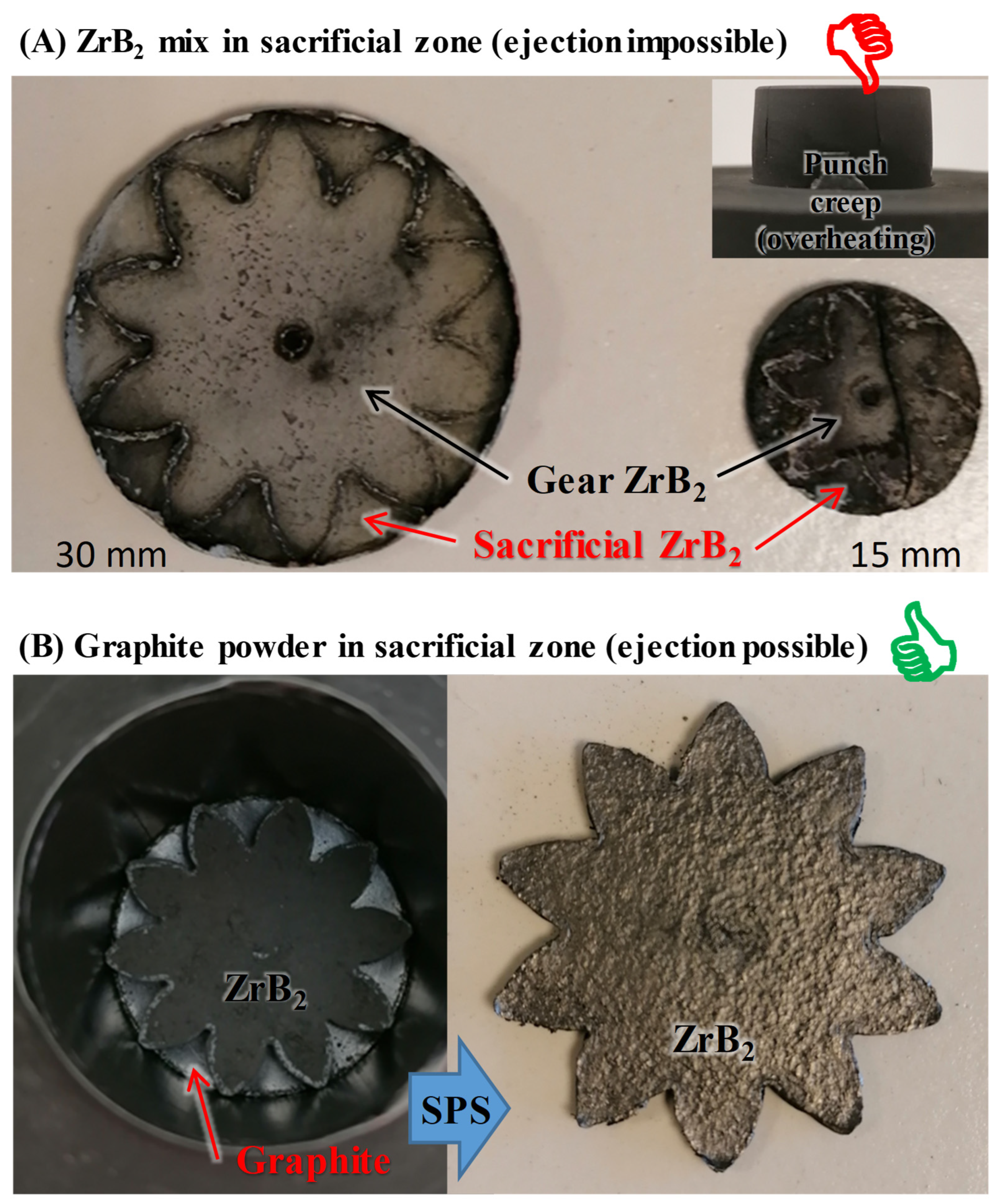
A Chempur ZrB2 powder (FW112.84 with 400 mesh particles and a purity of 99%) was used for this article. To decrease the sintering temperature, a small quantity of MoSi2 powder was added (MoSi2, Chempur FW152.13, 99.5% pure) as a sintering aid. In the work of reference [14], MoSi2 sintering aids were tested, and from the microstructure analysis, an amount of 4 wt% relative to the ZrB2 mass was identified as optimal for lowering the sintering temperature without the appearance of a second MoSi2 phase, which would reduce the properties of the sintered material. The powders were weighed, mixed, and de-agglomerated by attrition using zirconia balls, ethanol, and 4 h of milling. All the sintering experiments were conducted in an SPS device (HPD25 from FCT with a pulse pattern of 36 on −6 off) with graphite pressing tools of 15 and 30 mm inner diameters. This study comprises two experimental phases: the first is dedicated to optimizing the temperature cycle of the ZrB2-4 wt% MoSi2 mix, and the second part focuses on sintering tests for the fabrication of gears using the optimized cycle. The optimization of the sintering process used a pressure of 50 MPa applied from the start and 2 g of powder. The first SPS test consisted of a temperature ramp of 100 °C/min to 1750 °C, a temperature at which full densification should occur according to reference [14]. Since our configuration behaves differently, two additional tests were conducted at 1800 °C and 1830 °C, with holding times sufficient for full densification (15 min for 1800 °C and 12 min for 1830 °C). For each of these tests, the relative densities and open porosity were measured using the Archimedes method, and the polished microstructures were analyzed using a Jeol (JSM 7200 F) SEM device.
Regarding the gear tests, the main principle of these tests using the “DEFORMINT” method is illustrated in Figure 1A. The process consists of first 3D printing a polymer or composite ‘sub-mold’ of interfaces. This sub-mold was then placed in the graphite die of a uniaxial press within an SPS (spark plasma sintering) device. The target area of the part was filled with the powder of the material to be sintered. The remaining (sacrificial) zones can be filled with the same powder or with another material exhibiting similar compaction behavior. During SPS heating, the polymer partially degraded into carbon, enabling the post-sintering separation of the final part from the sacrificial material. The preparation involved the 3D printing of PLA gear interfaces (see Figure 1B). The printed interface served as a mold and was coated with graphite powder, then loaded with the ZrB2 powder mix, and inserted into the SPS die. At this stage, two tests were conducted: one where the same ZrB2 powder was placed in sacrificial zones (external to the gear heads) and another using graphite powder instead. The latter configuration is generally not recommended, as graphite powder has a significantly different SPS shrinkage compared to ZrB2. However, for this gear configuration, where ZrB2 surfaces are large compared to the sacrificial surfaces, the applied stress can be partially supported by the large ZrB2 area, which can help homogenize the shrinkage in the graphite zones.
This compensation mechanism is possible when the powder with the highest sintering temperature constitutes the main volume of the working space and when the latter is in a geometric configuration that allows it to support the primary applied stress. Such a configuration ensures a homogeneous SPS shrinkage field, even in cases of very different SPS powder behaviors. This kind of result was previously observed in reference [40] for the fabrication of complex shapes in Ti-6Al-4V using alumina as a sacrificial material. Despite the very different SPS behavior of alumina, the shape of the alumina sacrificial zones helps support the applied stress and allows the sintering of Ti-6Al-4V to occur at higher temperatures without deformation. This compensation mechanism is essential to the DEFORMINT method and strongly depends on the shapes of the powder zones with the highest sintering temperatures, which must support the applied stress. In the case of ZrB2, the use of graphite is advantageous for ejecting the shapes.

3. Results

The results of the sintering explorations for the ZrB2-4 wt% MoSi2 powder mix are reported in Figure 2. The final relative densities (Figure 2A) indicate that a minimum temperature of 1800 °C is required to achieve relative densities over 95% for the ZrB2 mix. Sciti and Nygren [14] suggest that 1750 °C may be sufficient; however, it is known that the apparent temperature in SPS strongly depends on the configuration, and a shift in the range of 50–100 K is possible [41,42]. The SEM microstructures (Figure 2B) are dense, with grains close to 1 µm in size for 1800 °C with a hardness of 1840 HV2 and a grain size slightly higher with a lower hardness 1550 HV2 for 1830 °C. There are black and white phases, and an EDS map (Figure 2C) was created to determine whether these zones represent porosity or secondary phases. The EDS map indicates that most of these zones are not porosity zones but rather molybdenum-rich phases (white zones, highlighted with a red cross) and silicon or carbon-rich phases (black zones). The cycle at 1830 °C was selected to sinter the gear parts, as it provided good densification without excessive grain growth and maintained a temperature margin (+30 °C) to ensure densification in a condition where the interface can locally disturb the densification.
The gear tests using ZrB2 as a sacrificial material are reported in Figure 3A. The gears can be sintered, but the sacrificial parts of the pellet cannot be easily removed to eject the gear. As can be seen, the gear shape is well preserved, and it is possible to fracture the sacrificial part to eject the gear; however, this method can lead to severe damage to the gear. Regarding the 15 mm gear test, the outcome was similar, but we noticed that the configuration results in the significant overheating of the punches, leading to deformation and cracking [43]. This is often due to the significant difference between the punch section and the die section [41,44,45]. Since using the same powder in the sacrificial zone does not facilitate shape ejection, the best solution is to use graphite powder in the sacrificial zones. Graphite powder does not behave like a sintering compact, but much more like a cold compaction material, which uses a porous plasticity model [46,47,48]. If the ZrB2 zones are strong enough to support the applied stress, the yield surface of the graphite powder, which evolves with porosity and temperature, may adapt, imposing a densification that follows that of ZrB2. The results of the gear test with sacrificial graphite are reported in Figure 3B. As shown, the gear was successfully ejected from the graphite, which was expected because graphite powder did not sinter in the temperature regime explored. Only the central hole was not well-reproduced, as it was very small in the original design and the printed wall around was thicker than expected, reducing its diameter to about 1 mm. This made it difficult to load and eject, so we chose to leave it closed. This demonstrates that very thin features are not well suited to the DEFORMINT method, as the interface can have a significant influence when it is close to the part thickness. Interestingly, the graphite compaction did not lead to significant deformation of the gear shape. The outer diameter was reduced by only 0.2 mm, while the inner diameter in-creased by 1.5 mm. This inner thin feature was particularly sensitive to shrinkage effects. It appears that the graphite compaction behavior aligns well with the ZrB2 compaction while retaining the shape against creep radial deformations.

4. Conclusions

To conclude, this study investigates the fabrication of ZrB2 gears by SPS. The sintering of ZrB2 powder doped with 4 wt% MoSi2 was adapted to our equipment and demonstrated optimal results at 1800 °C with a 15 min dwell time under 50 MPa. A higher temperature of 1830 °C was tested and used with the interface to provide a sufficient safety margin. This approach utilizes the ‘DEFORMINT’ method, where simple 3D-printed interfaces are used as powder containers and placed in the SPS die to facilitate preparation. Two strategies are explored: using either the same powder (ZrB2) or graphite as the sacrificial material. In the ZrB2 sacrificial approach, it was not possible to eject the gear from the sacrificial parts, even with the graphite coating. However, the test using graphite throughout the entire sacrificial zone resulted in successful gear ejection while preserving the gear shape. This outcome demonstrates that shapes, like gears, which have a large area exposed to applied stress, can effectively support it. The graphite exhibits compaction behavior similar to that of cold powder compaction. In this well-supported configuration, the shrinkage of the graphite follows that of the ZrB2, which governs the sintering process. This approach can be extended to less-supported shapes, but additional ZrB2 zones will need to be added to the sacrificial zones to adequately support the applied stress. This approach can be generalized to other ceramic systems beyond ZrB2.

Author Contributions

Conceptualization, investigation, methodology, formal analysis, and writing—original draft preparation, C.M.; methodology, visualization, resources, and writing—review and editing, C.E. All authors have read and agreed to the published version of the manuscript.

Funding

This research received no external funding.

Institutional Review Board Statement

Not applicable.

Informed Consent Statement

Not applicable.

Data Availability Statement

The original contributions presented in this study are included in the article. Further inquiries can be directed to the corresponding author.

Acknowledgments

The authors would like to thank Jérome Lecourt, Geoffroy Chevallier, and Christelle Bilot for their contributions to the SPS tests, hardness tests, and SEM imaging.

Conflicts of Interest

The authors declare no conflicts of interest.

Abbreviations

The following abbreviations are used in this manuscript:
UHTCsUltra-High-Temperature Ceramics
PLAPolylactic Acid
SPSSpark Plasma Sintering
HPHot Pressing
HIPHot Isostatic Pressing
GPSGas Pressure Sintering
AMAdditive Manufacturing
FDMFuse Deposition Modeling

References

  1. Wyatt, B.C.; Nemani, S.K.; Hilmas, G.E.; Opila, E.J.; Anasori, B. Ultra-High Temperature Ceramics for Extreme Environments. Nat. Rev. Mater. 2023, 9, 773–789. [Google Scholar] [CrossRef]
  2. Wuchina, E.; Opila, E.; Fahrenholtz, W.; Talmy, I. UHTCs: Ultra-High Temperature Ceramic Materials for Extreme Environment Applications. Electrochem. Soc. Interface 2007, 16, 30–36. [Google Scholar] [CrossRef]
  3. Orrù, R.; Cao, G. Ultra-High Temperature Ceramics by Spark Plasma Sintering. In Spark Plasma Sintering; Elsevier: Amsterdam, The Netherlands, 2019; pp. 49–76. [Google Scholar]
  4. Justin, J.F.; Jankowiak, A. Ultra High Temperature Ceramics: Densification, Properties and Thermal Stability. Aerospace Lab 2011, 3, 1–11. [Google Scholar]
  5. Nisar, A.; Hassan, R.; Agarwal, A.; Balani, K. Ultra-High Temperature Ceramics: Aspiration to Overcome Challenges in Thermal Protection Systems. Ceram. Int. 2022, 48, 8852–8881. [Google Scholar] [CrossRef]
  6. Golla, B.R.; Mukhopadhyay, A.; Basu, B.; Thimmappa, S.K. Review on Ultra-High Temperature Boride Ceramics. Prog. Mater. Sci. 2020, 111, 100651. [Google Scholar] [CrossRef]
  7. Fahrenholtz, W.G.; Hilmas, G.E. Ultra-High Temperature Ceramics: Materials for Extreme Environments. Scr. Mater. 2017, 129, 94–99. [Google Scholar] [CrossRef]
  8. Silvestroni, L.; Kleebe, H.-J.; Fahrenholtz, W.G.; Watts, J. Super-Strong Materials for Temperatures Exceeding 2000 °C. Sci. Rep. 2017, 7, 40730. [Google Scholar] [CrossRef] [PubMed]
  9. Huang, K.; Chen, W.; Wu, M.; Wang, J.; Jiang, K.; Liu, J. Microstructure and Densification of the Ti6Al4V–70%TiB2 Metal-Ceramic by Coupled Multi-Physical Fields-Activated Sintering. J. Alloys Compd. 2020, 820, 153091. [Google Scholar] [CrossRef]
  10. Fahrenholtz, W.G.; Hilmas, G.E.; Li, R. Densification of Ultra-Refractory Transition Metal Diboride Ceramics. Sci. Sinter. 2020, 52, 1–14. [Google Scholar] [CrossRef]
  11. Grasso, S.; Saunders, T.; Porwal, H.; Cedillos-Barraza, O.; Jayaseelan, D.D.; Lee, W.E.; Reece, M.J. Flash Spark Plasma Sintering (FSPS) of Pure ZrB2. J. Am. Ceram. Soc. 2014, 97, 2405–2408. [Google Scholar] [CrossRef]
  12. Fahrenholtz, W.G.; Hilmas, G.E.; Talmy, I.G.; Zaykoski, J.A. Refractory Diborides of Zirconium and Hafnium. J. Am. Ceram. Soc. 2007, 90, 1347–1364. [Google Scholar] [CrossRef]
  13. De Bona, E.; Manière, C.; Sglavo, V.M.; Biesuz, M. Ultrafast High-Temperature Sintering (UHS) of ZrB2-Based Materials. J. Eur. Ceram. Soc. 2024, 44, 567–573. [Google Scholar] [CrossRef]
  14. Sciti, D.; Nygren, M. Spark Plasma Sintering of Ultra Refractory Compounds. J. Mater. Sci. 2008, 43, 6414–6421. [Google Scholar] [CrossRef]
  15. Petzow, G.; Herrmann, M. Silicon Nitride Ceramics. In High Performance Non-Oxide Ceramics II; Springer: Berlin/Heidelberg, Germany, 2002; pp. 47–167. ISBN 978-3-540-45623-0. [Google Scholar]
  16. Riley, F.L. Silicon Nitride and Related Materials. J. Am. Ceram. Soc. 2004, 83, 245–265. [Google Scholar] [CrossRef]
  17. Schneider, J.A.; Risbud, S.H.; Mukherjee, A.K. Rapid Consolidation Processing of Silicon Nitride Powders. J. Mater. Res. 1996, 11, 358–362. [Google Scholar] [CrossRef]
  18. Grippi, T.; Béhar-Lafenêtre, S.; Friedrich, H.; Haas, D.; Schenderlein, U.; Marinel, S.; Manière, C. Densification Modeling for Gas Pressure Sintered Silicon Nitride-Based Ceramics with Thermo-Optical Dilatometry. J. Eur. Ceram. Soc. 2024, 44, 822–830. [Google Scholar] [CrossRef]
  19. Grippi, T.; Béhar-Lafenetre, S.; Friedrich, H.; Haas, D.; Schenderlein, U.; Marinel, S.; Manière, C. Finite Element Simulation for Si3N4 Heating and Sintering. J. Eur. Ceram. Soc. 2024, 44, 116703. [Google Scholar] [CrossRef]
  20. Rahaman, M.N. Sintering of Ceramics; CRC Press: Boca Raton, FL, USA, 2007; ISBN 9780849372865. [Google Scholar]
  21. Lee, S.-H.; Tanaka, H.; Kagawa, Y. Spark Plasma Sintering and Pressureless Sintering of SiC Using Aluminum Borocarbide Additives. J. Eur. Ceram. Soc. 2009, 29, 2087–2095. [Google Scholar] [CrossRef]
  22. Hotta, M.; Hojo, J. Inhibition of Grain Growth in Liquid-Phase Sintered SiC Ceramics by AlN Additive and Spark Plasma Sintering. J. Eur. Ceram. Soc. 2010, 30, 2117–2122. [Google Scholar] [CrossRef]
  23. Raju, K.; Yoon, D.-H. Sintering Additives for SiC Based on the Reactivity: A Review. Ceram. Int. 2016, 42, 17947–17962. [Google Scholar] [CrossRef]
  24. Grasso, S.; Saunders, T.; Porwal, H.; Milsom, B.; Tudball, A.; Reece, M. Flash Spark Plasma Sintering (FSPS) of α and β SiC. J. Am. Ceram. Soc. 2016, 99, 1534–1543. [Google Scholar] [CrossRef]
  25. Manière, C.; Nigito, E.; Durand, L.; Weibel, A.; Beynet, Y.; Estournès, C. Spark Plasma Sintering and Complex Shapes: The Deformed Interfaces Approach. Powder Technol. 2017, 320, 340–345. [Google Scholar] [CrossRef]
  26. Laptev, A.M.; Bram, M.; Garbiec, D.; Räthel, J.; van der Laan, A.; Beynet, Y.; Huber, J.; Küster, M.; Cologna, M.; Guillon, O. Tooling in Spark Plasma Sintering Technology: Design, Optimization, and Application. Adv. Eng. Mater. 2024, 26, 2301391. [Google Scholar] [CrossRef]
  27. Guillon, O.; Gonzalez-Julian, J.; Dargatz, B.; Kessel, T.; Schierning, G.; Räthel, J.; Herrmann, M. Field-Assisted Sintering Technology/Spark Plasma Sintering: Mechanisms, Materials, and Technology Developments. Adv. Eng. Mater. 2014, 16, 830–849. [Google Scholar] [CrossRef]
  28. Voisin, T.; Monchoux, J.-P.; Durand, L.; Karnatak, N.; Thomas, M.; Couret, A. An Innovative Way to Produce γ-TiAl Blades: Spark Plasma Sintering. Adv. Eng. Mater. 2015, 17, 1408–1413. [Google Scholar] [CrossRef]
  29. Manière, C.; Durand, L.; Weibel, A.; Estournès, C. Spark-Plasma-Sintering and Finite Element Method: From the Identification of the Sintering Parameters of a Submicronic α -Alumina Powder to the Development of Complex Shapes. Acta Mater. 2016, 102, 169–175. [Google Scholar] [CrossRef]
  30. Manière, C.; Durand, L.; Weibel, A.; Chevallier, G.; Estournès, C. A Sacrificial Material Approach for Spark Plasma Sintering of Complex Shapes. Scr. Mater. 2016, 124, 126–128. [Google Scholar] [CrossRef]
  31. Matsugi, K.; Kuramoto, H.; Yanagisawa, O.; Kiritani, M. A Case Study for Production of Perfectly Sintered Complex Compacts in Rapid Consolidation by Spark Sintering. Mater. Sci. Eng. A 2003, 354, 234–242. [Google Scholar] [CrossRef]
  32. German, R.M. Powder Metallurgy of Iron and Steel. Choice Rev. Online 1998, 36, 36–0981. [Google Scholar] [CrossRef]
  33. German, R.M. Sintering Theory and Practice; Wiley: Hoboken, NJ, USA, 1996; ISBN 978-0-471-05786-4. [Google Scholar]
  34. Maniere, C.; Durand, L.; Estournès, C. Use of a Deformable Interface for the Production of Complex Parts. Patent WO2017077028 A1, 4 November 2016. [Google Scholar]
  35. Manière, C.; Torresani, E.; Olevsky, E.A. Simultaneous Spark Plasma Sintering of Multiple Complex Shapes. Materials 2019, 12, 557. [Google Scholar] [CrossRef]
  36. Manière, C.; Lee, G.; Olevsky, E.A. Flash Sintering of Complex Shapes. Appl. Mater. Today 2022, 26, 101293. [Google Scholar] [CrossRef]
  37. Manière, C.; Olevsky, E.A. In Situ Partially Degradable Separation Interface for Fabrication of Complex near Net Shape Objects by Pressure Assited Sintering. U.S. Patent 2021/0016499 A1, 27 March 2019. [Google Scholar]
  38. Le Cloarec, J.; Marinel, S.; Estournès, C.; Dehmas, M.; Folton, C.; Manière, C. Stereolithography Coupled with Spark Plasma Sintering to Produce Ti-6Al-4V Complex Shapes. J. Manuf. Process. 2024, 114, 122–135. [Google Scholar] [CrossRef]
  39. Le Cloarec, J.; Marinel, S.; Estournès, C.; Dehmas, M.; Manière, C. Ti–6Al–4V Complex Shape Production by Spark Plasma Sintering with Ceramic–Metal Sacrificial Powder and Interface 3D Printing. Prog. Addit. Manuf. 2024, 10, 3321–3334. [Google Scholar] [CrossRef]
  40. Van der Laan, A.; Epherre, R.; Chevallier, G.; Beynet, Y.; Weibel, A.; Estournès, C. Fully Coupled Electrothermal and Mechanical Simulation of the Production of Complex Shapes by Spark Plasma Sintering. J. Eur. Ceram. Soc. 2021, 41, 4252–4263. [Google Scholar] [CrossRef]
  41. Manière, C.; Durand, L.; Brisson, E.; Desplats, H.; Carré, P.; Rogeon, P.; Estournès, C. Contact Resistances in Spark Plasma Sintering: From in-Situ and Ex-Situ Determinations to an Extended Model for the Scale up of the Process. J. Eur. Ceram. Soc. 2017, 37, 1593–1605. [Google Scholar] [CrossRef]
  42. Le Cloarec, J.; Marinel, S.; Chevallier, G.; Estournès, C.; Manière, C. Impact of Graphite Foil Rolling on the Thermal Field Homogeneity of Spark Plasma Sintering. Ceram. Int. 2023, 49, 19545–19551. [Google Scholar] [CrossRef]
  43. Manière, C.; Lee, G.; McKittrick, J.; Maximenko, A.; Olevsky, E.A. Graphite Creep Negation during Flash Spark Plasma Sintering under Temperatures Close to 2000 °C. Carbon 2020, 162, 106–113. [Google Scholar] [CrossRef]
  44. Achenani, Y.; Saâdaoui, M.; Cheddadi, A.; Fantozzi, G. Finite Element Analysis of the Temperature Uncertainty during Spark Plasma Sintering: Influence of the Experimental Procedure. Ceram. Int. 2017, 43, 15281–15287. [Google Scholar] [CrossRef]
  45. Achenani, Y.; Saâdaoui, M.; Cheddadi, A.; Bonnefont, G.; Fantozzi, G. Finite Element Modeling of Spark Plasma Sintering: Application to the Reduction of Temperature Inhomogeneities, Case of Alumina. Mater. Des. 2017, 116, 504–514. [Google Scholar] [CrossRef]
  46. Torresani, E.; Carrillo, M.; Haines, C.; Martin, D.; Olevsky, E. Fabrication of Powder Components with Internal Channels by Spark Plasma Sintering and Additive Manufacturing. J. Eur. Ceram. Soc. 2023, 43, 1117–1126. [Google Scholar] [CrossRef]
  47. Grippi, T.; Torresani, E.; Maximenko, A.L.; Olevsky, E.A. Additive Manufacturing-Assisted Sintering: Low Pressure, Low Temperature Spark Plasma Sintering of Tungsten Carbide Complex Shapes. Ceram. Int. 2024, 50, 37228–37240. [Google Scholar] [CrossRef]
  48. Ranjit, K.V.; Mahesh, N.S.; Anwar, M.I. Numerical Analysis of Powder Compaction to Obtain High Relative Density in ‘601AB’ Aluminum Powder. SASTECH 2012, 11, 79–84. [Google Scholar]
Figure 1. (A) DEFOMINT methods used to fabricate complex shapes by SPS, within gray sacrificial zones; (B) shape design and photo of the printed PLA interface.
Ceramics 08 00081 g001
Figure 2. Results of the ZrB2-4wt%MoSi2 powder SPS cycle optimization with (A) the relative density and open porosity; (B) the SEM microstructures; and (C) EDS map on the 1830 °C test.
Ceramics 08 00081 g002
Figure 3. ZrB2 gear SPS tests: (A) SPS tests using the same ZrB2 mix in sacrificial zones. The sintered sacrificial part results in adhesion to the gear that cannot by ejected; for the 15 mm test, important overheating is present in the punch’s external part, which cause graphite deformation and cracks; (B) SPS test using graphite powder in the sacrificial zones showing better results, with a successfully ejected gear with a preserved shape.
Ceramics 08 00081 g003
Disclaimer/Publisher’s Note: The statements, opinions and data contained in all publications are solely those of the individual author(s) and contributor(s) and not of MDPI and/or the editor(s). MDPI and/or the editor(s) disclaim responsibility for any injury to people or property resulting from any ideas, methods, instructions or products referred to in the content.

