Article

Reduction of Ceramic Wear by Concave Dimples on the Bearing Surface in CoC Hip Implants: A Finite Element Analysis

by
Mario Ceddia
1,*,
Arcangelo Morizio
2,
Giuseppe Solarino
2,* and
Bartolomeo Trentadue
1
1
Department of Mechanics, Mathematics and Management, Polytechnic of Bari University, 70125 Bari, Italy
2
Department of Translational Biomedicine and Neuroscience, University of Bari, 70124 Bari, Italy
*
Authors to whom correspondence should be addressed.
Ceramics 2025, 8(2), 51; https://doi.org/10.3390/ceramics8020051
Submission received: 27 March 2025 / Revised: 24 April 2025 / Accepted: 30 April 2025 / Published: 7 May 2025
(This article belongs to the Special Issue Mechanical Behavior and Reliability of Engineering Ceramics)

Abstract

:
The wear of hip prostheses represents a significant challenge for the longevity and functionality of joint implants. Recent studies have explored surface texturing of prostheses as a strategy to enhance tribological performance. This study aims to evaluate the impact of textured ceramic surfaces with dimples on wear and friction reduction in ceramic-on-ceramic (CoC) prostheses. Materials and Methods: Three-dimensional models of ceramic surfaces with and without dimples were created. Contact pressure was analyzed and wear volume was estimated using Archard’s law. Simulations were conducted using finite element methods (FEM) under various loading conditions. Results: Numerical simulations demonstrated that the wear rate for the dimpled femoral head was 0.2369 mm3/year, compared to 0.286 mm3/year for the smooth counterpart, highlighting a wear reduction of 17.2%. Conclusions: The integration of textured surfaces with dimples in ceramic prostheses can substantially improve their functionality and durability, representing a promising approach to addressing the issues associated with hip prosthesis wear.

1. Introduction

The goal of total hip arthroplasty (THA) is to replace a damaged or compromised joint with an artificial joint [1,2]. This procedure is usually performed for conditions such as arthritis, inflammation, or in more severe cases such as hip fractures [3]. In the United States, more than 285,000 total hip replacements (THA) are performed annually to treat degenerative joint disease [4]. A variety of biomaterials are used in the manufacture of hip implants, including metals, polymers, and ceramics. There are several types of prosthetic joints available, including ceramic-on-ceramic (CoC), ceramic-on-metal (CoM), ceramic-on-polyethylene (CoP), metal-on-metal (MoM), and metal-on-polyethylene (MoP) combinations [5,6,7,8]. In 2014, more than half of new hip replacements in the United States were CoP implants (51%), followed by MoP (42%), MoM (4%), and CoC (3%) [9,10]. Major causes of MoP hips failure include wear of the polyethylene liner, caused by interaction with the Co-Cr femoral component, resulting in the generation of particles that can accelerate contact surface degradation. In addition, biological responses to the presence of wear debris can induce periprosthetic osteolysis, which can compromise the stability of the implant [11]. It has been observed that although cross-linked polyethylene reduces wear to some extent, it can still contribute to osteolysis phenomena [11,12,13]. Minimizing friction and wear rate are essential to increase the longevity of the prosthesis, especially with the use of femoral heads that allow a greater range of motion [14]. The current engineering approach to addressing wear in implants involves improving the mechanical properties of the polyethylene component and creating ultra-smooth bearing surfaces, along with the development of ceramic-on-polyethylene (CoP) and ceramic-on-ceramic (CoC) prostheses. For example, CoC bearing surfaces have an average roughness of less than 5 nm, allowing them to operate in an (elasto-hydro)dynamic lubrication regime, which helps to reduce friction and wear [15]. In an analysis conducted by Buttaro et al. [16], a retrospective review was performed of 939 cases (880 patients) who underwent primary total hip arthroplasty with CoC bearing surfaces. The results showed an exceptional average survival rate of 99.3% over a period of 2–10 years. In addition, Lee et al. [17] reviewed data on 2.78 million AMC ceramic femoral heads implanted worldwide and found a clinical fracture incidence of only 1 in 100,000 for contemporary AMC ceramic femoral heads. Furthermore, a study by Solarino et al. [18] found that CoC is the ideal choice for younger and more active patients due to its reliability and longevity, highlighted by the lack of material-related complications. CoC implants also allow the use of femoral heads larger than 28 mm without increasing the coefficient of friction, which is not always possible with CoCr heads due to concerns about polyethylene wear [19,20]. In a comparative analysis by Higuch et al. [21], the average wear rate on anteroposterior (AP) radiographs was 0.0037 mm/year for CoC compared to 0.0051 mm/year for MoM. Therefore, the lower wear rates of CoC prostheses could indicate a longer implant life and fewer problems related to osteolysis and revision compared to MoP, MoM, and CoP. However, despite the excellent results observed with CoC, the number of revision surgeries is steadily increasing, especially in younger and adult patients, and is expected to double by 2026 [22,23,24,25,26]. This could have a significant social and economic impact if effective preventive measures are not implemented [27,28]. Various surface modification techniques have been developed to extend the life of joint prostheses. These include surface texturing (dimpling) and the application of surface coatings. These methods are typically applied to the surfaces of the femoral head [29,30,31,32,33]. Surface texturization helps to improve tribological performance by increasing the thickness of the lubricating film between contacting components, acting as a lubricant reservoir.
Increasing the thickness of the lubricant film by creating dimples on the surface of the femoral head allows direct contact between the surfaces to be avoided, reducing the risk of dry friction. This system helps to trap wear particles under mixed lubrication conditions, preventing damage to the bearing surface during movement. Roy et al. [34] documented a significant 22% reduction in friction and 53% reduction in wear on textured surfaces compared to non-textured surfaces. Vaidyanathan et al. [35] found that the use of a textured CoCrMo femoral head in conjunction with a UHMWPE liner resulted in a reduction in coefficient of friction of up to 36% and a reduction in wear of up to 69%. Finite Element Methods (FEM) provide an effective alternative to laboratory testing [36,37,38,39]. These methods allow faster and more cost-effective simulations of different loading and kinematic scenarios. However, some studies, such as that of Jamari et al. [40], have used simplified models that do not always accurately reflect physiological conditions. Despite the lack of studies on the wear volume of CoC prostheses, there is a great deal of experimental and numerical research on the textured surfaces of MOP and COP prostheses [41]. The aim of this research is to analyze the contact pressure on the surface of the acetabular cup with and without the addition of dimples in a ceramic-on-ceramic (CoC) configuration. The analysis is performed using 3D dry contact models with simplified loading conditions to obtain immediate results. In addition, the wear rate for both models is estimated using Archard’s law to validate the null hypothesis that the introduction of dimples would significantly reduce the wear rate.

2. Materials and Methods
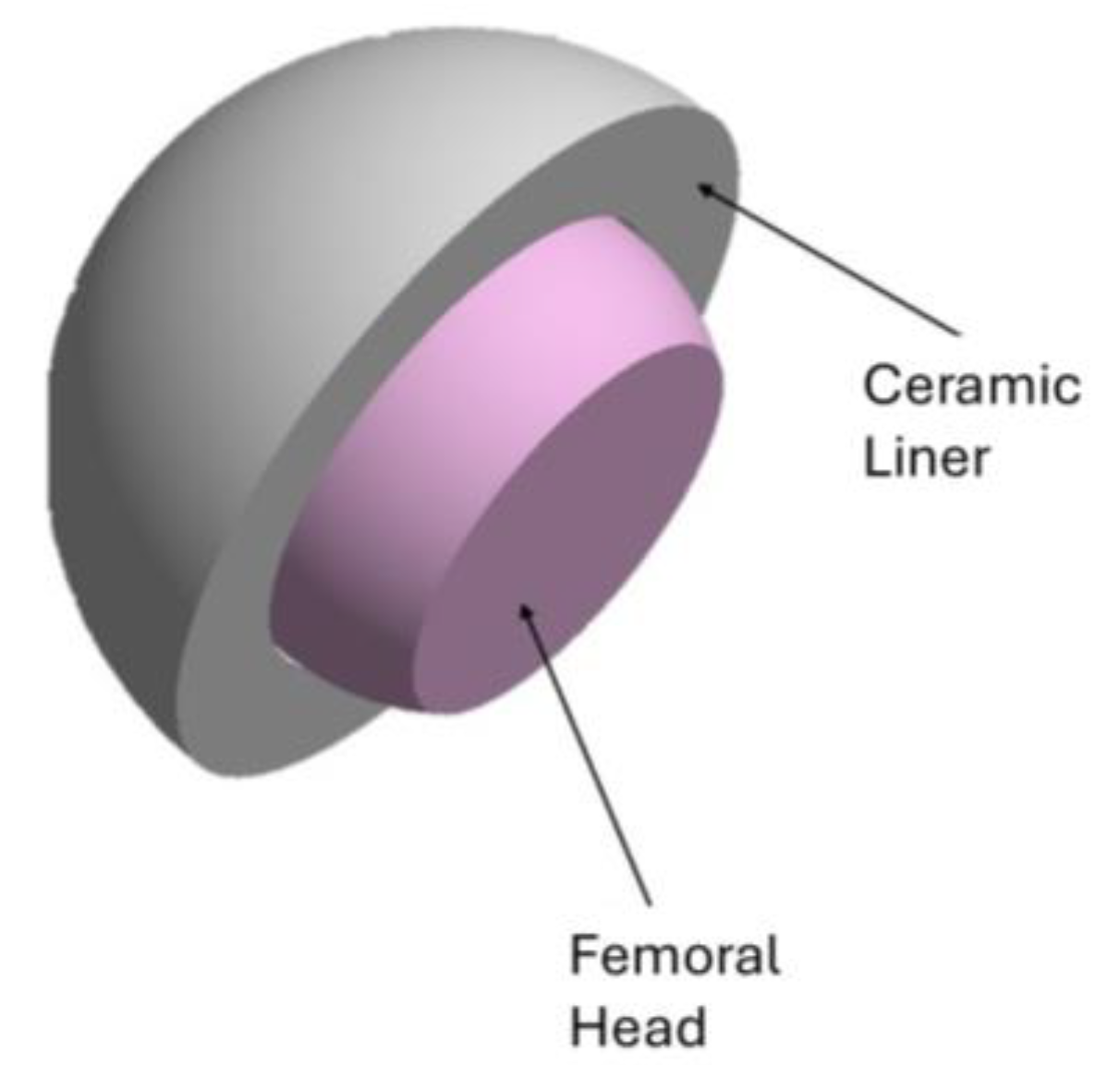
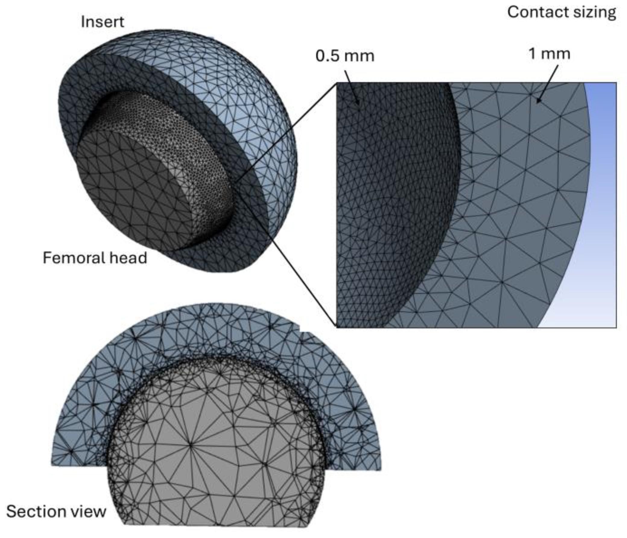
The CoC hip implant has a 32 mm diameter head made of Biolox Delta zirconia matrix [42] with a Young’s modulus of 350 GPa and a Poisson’s coefficient of 0.26. The acetabular insert has an internal diameter of 32.49 mm, a thickness of 8 mm, and an external diameter of 40 mm. It is made of zirconia with a modulus of elasticity of 210 GPa and a Poisson’s coefficient of 0.26. In addition, the distance between the acetabular insert and the femoral head is 0.245 mm (Figure 1). The two components were manufactured and assembled using the 3D modelling software Autodesk Inventor 2024 [43,44].
Based on the geometric parameters of dimples reported in the literature [41], a model was created with the addition of circular dimples as shown in Figure 2. Using Autodesk Inventor’s geometric modeling commands, dimples were created that are 0.5 mm in diameter and 0.25 mm deep. The industrial technology for creating dimples on ceramic surfaces using lasers is known as laser surface texturing (LST) or laser surface treatment. This process modifies the surface properties of the material, resulting in microstructures that improve tribological properties such as reduced friction and wear.
One of the important parameters describing the geometry of textured features is the aspect ratio ɛ [45]. It is defined as the ratio of the depth (h) to the equivalent diameter (d) of the textured feature. Deep pits with an aspect ratio ɛ > 0.1 act as lubricant reservoirs, reducing friction and wear in mixed lubrication conditions and providing lubricant to contact surfaces in deficient conditions. They also provide trapping of wear debris that would otherwise scratch the surface. Conversely, for aspect ratios ɛ < 0.1, there is a micro-hydrodynamic support effect which increases the pressure and thickness of the lubricant film between the bearing surfaces, reducing contact and, consequently, friction and wear (Figure 3).
In this study, an aspect ratio of ɛ = 0.5 was chosen, contributing to a higher load capacity and a reduction in the coefficient of friction. The materials considered in this analysis were modelled with isotropic linear behavior as they are characterized as brittle materials that do not exhibit yielding behavior [43,46,47,48] (Table 1).

2.1. FEA Modeling

The classical workflow for an FEM analysis in (Ansys® R 2024) software consists of four steps: (1) pre-processing (PREP 7); (2) solving (SOLU); (3) post-processing (POST 1 or POST 26); (4) validation. In the pre-processing step, materials are selected, and the geometry of the model is created. During the solution step, boundary conditions are applied, and solution options are set. In the post-processing step, results are obtained, and analysis is performed Figure 4.
While the acetabular insert and the femoral head were discretized with a mesh size of 1 mm, the contact area was refined using the Contact refinement command. A finer mesh of 0.5 mm was used to better represent the stress distribution in this area (Figure 5).
These parameters were subsequently validated by convergence analysis, which showed an error in the contact pressure results of less than 1% using a mesh of 0.5 mm and 0.6 mm. The element order was set to Quadratic (SOLID 187), and the error limits were set to Standard Mechanical. The most used elements are hexagonal and tetrahedral. Hexagonal elements are generally preferred due to their higher accuracy but are more expensive to calculate [49,50,51,52]. The choice between the two types of elements depends on the level of accuracy required. A mesh that is too coarse leads to imprecise solutions but low computational cost, while a fine mesh gives very accurate results, may become computationally impractical. Tetrahedral elements were therefore used in this study because they allow easier meshing, resulting in a total of 15,479 nodes and 9452 elements.

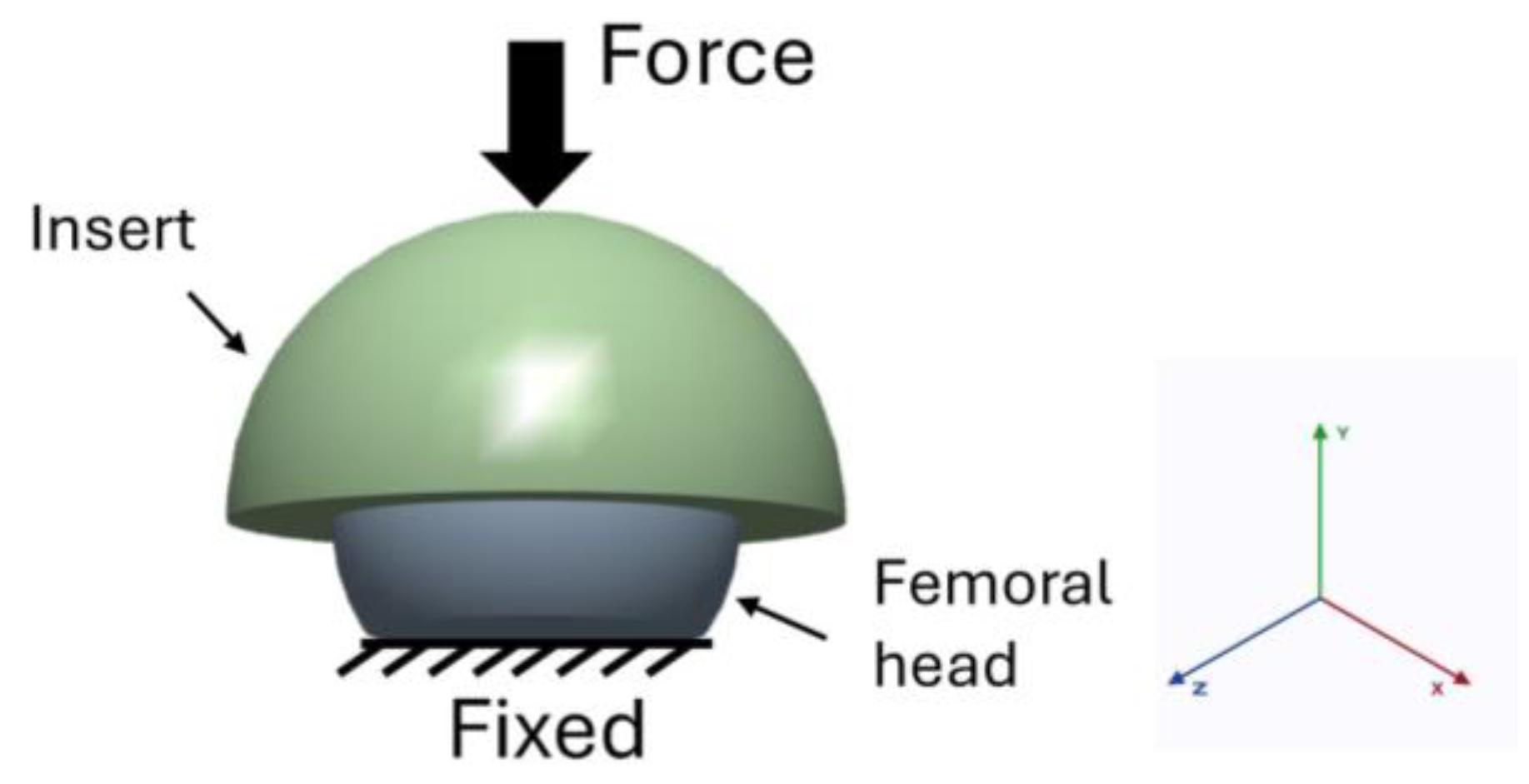
2.2. Boundary Conditions

Regarding contact conditions, the femoral head is modelled as ‘Target Body’, as it is the strongest material, while the acetabular insert is defined as ‘Contact Body’. Eight-node linear 3D elements (CONTA 174) were used for the contact, while four-node linear 3D elements (CONTA 170) were used for the target. A frictional contact between the two surfaces was then assigned using a Ceramic-Ceramic friction coefficient of 0.12 [53,54] (Figure 6).
The calculation is simplified through the study of Bergmann et al. [55] and shows that the resultant force is equivalent to the vertical component. Therefore, only this component is considered in this analysis for an individual weighing 80 kg. In this study, various activities shown in Table 2 were considered. Then, the equivalent forces for the individual activities were applied to the upper surface of the insert.
The lower part of the femoral head was fully constrained in all directions, while a vertical load was applied to the upper surface of the insert Figure 7.
In this study, the normal contact case is defined to represent the basic interaction between surfaces, concentrating on axial loading conditions during femoral head articulation within the acetabulum. While rotation plays a critical role in real-life scenarios, more detailed analyses can incorporate rotational dynamics in subsequent studies. Future finite element analyses may explore how dynamic loading and rotational forces impact contact mechanics and wear over time, particularly in the context of dynamic testing conditions.
A total of 10 cases (five model a, five model b) were analyzed for the various activities shown in Table 2.

2.3. Calculation of the Wear Rate

Using Archard’s formulation [56,57], wear can be calculated. This assumes that the two contact surfaces are not perfectly smooth but consist of asperities. It is also assumed that only the higher asperities carry the normal load W during the sliding motion.
Given a small sliding section ds and a small load increment dW, we assume that the volume of material removed dV is proportional to these quantities and inversely proportional to the hardness H of the “soft” material:
d V = k d W   d s H
where k is a dimensionless proportionality constant (incorporating the fraction of asperities broken and transported as wear particles).
Integrating over the total sliding distance S and the total load W gives Archard’s volumetric law:
V = d V = 0 W 0 S K d W d s H = K W S H
In the case of the femoral head and insert coupling, where R is the radius of the head with a circumference of length 2πR, Archard’s formula can be rewritten as:
V t o t = K W S H = K W 2 π R H
Equation (3) is scaled to reproduce actual daily loading conditions (10,000 cycles) and then adjusted to an annual period with an additional scaling factor of 365. A factor of 1000 was also applied to convert the results to mm3 per year. The final equation of Archard’s law applied in this study is Equation (4), where the contact area S l was calculated by subtracting the area of the femoral head from the hemispherical area of the insert, resulting in a contact area of 1608.5 mm2.
V = k w σ c A S l 1000 365 10 3
where:
  • k w : wear coefficient in mm3/Nm.
  • σ c : contact pressure in MPa
  • A : contact area in mm2
  • S l : sliding distance in mm.
The wear coefficient kw can be obtained from experimental studies such as pin-on-disc tests or hip wear simulators [57], considering the surface roughness Ra. In the present study, a kw value of 1 × 10⁻⁸ is used for a ceramic-ceramic contact in a CoC joint. The results of the FEM simulation, such as contact pressure and sliding distance, can then be used to calculate the wear volume during different activities using Equation (4).

3. Results

Numerical simulation of this model was conducted to determine the maximum value of contact pressure and sliding distance, assuming static loading conditions to simplify the analysis. Using Archard’s wear rate formulation, it is possible to estimate the volume of wear that occurs on the inner surface of the acetabular liner. The situation involving the maximum load is the activity of climbing stairs, in which the body weight increases by 2.6 percent. Figure 8 shows the contact stress found during stair-climbing activity. From these findings, it can be seen that the maximum stress values are located in the central region of the inner surface of the liner, while the minimum values are located in the circumferential area.
For the model without dimples (model A) a maximum contact stress of 0.7047 MPa is reached, whereas for the model with dimples (model B) 0.5419 MPa is reached. Furthermore, the maximum stress observed at the femoral head for model A is 0.5043 MPa, while for model B lower values of 0.3097 MPa reached Figure 9.
From Figure 9 the maximum stress value is reached in the c zone for both models. While the lowest contact stress values are reached in zone a, 0.4292 MPa for model A and 0.4184 MPa for model B. Regarding the sliding distance, the relative values in mm are shown in Table 3.
In the case of a dimpled model, the sliding distance is less than in the case of a model with a smooth femoral head.

Wear Volume

The wear volume (V) of the surface modified femoral head was calculated using the modified Archard wear equation. This method allows the quantitative measurement of material loss from artificial implant components, which is critical in assessing their performance and durability over time. To estimate the annual wear volume, a condition of 10,000 load cycles per day, a femoral head surface roughness of 0.008 μm and a radius of 16 mm was assumed. Figure 10 shows that the wear rate of a femoral head is higher during stair-climbing activities. In this activity, the model with dimples exhibits a lower wear rate (0.2369 mm3/year) compared to the smooth head model (0.286 mm3/year). Therefore, the dimples may help distribute pressure more evenly across the contact surface between the femoral head and the insert. This contributes to reducing localized stress peaks, which are often responsible for excessive wear. Furthermore, the dimples reduce the contact area, distributing the load over a larger surface. As a result, a smaller contact area can lead to lower wear, as there is less direct material in contact to wear away. The dimples can also act as traps for debris, reducing friction and wear caused by direct contact between surfaces.
Sitting is the activity that causes the least wear, with values of 0.0358 mm3 for the model without dimples and 0.01369 mm3 for the model with dimples. These results are consistent with previous clinical studies and suggest that the empirical relationships developed may be useful in the design of hip prostheses.

4. Discussion

The prevention of aseptic loosening of artificial joints poses a significant challenge in orthopedic surgery. It is crucial to improve the lubrication properties of friction surfaces and reduce the generation of wear particles [58,59,60]. This necessity can be justified on three main grounds. First, high friction can generate elevated shear stresses at the bone-implant interface. This mechanism is often responsible for aseptic loosening, which can compromise implant stability [61,62]. Therefore, it is essential to mitigate friction to prevent such events. Second, numerous studies have shown that high molecular weight polyethylene (UHMWPE) liners wear at rates between 0.1 and 0.2 mm per year [63], resulting in a thick reduction of approximately 1–2 mm over a decade. In situations where the liner is thin, increased wear can lead to higher friction with the femoral head. This friction is associated with conditions such as metallosis, which can lead to osteolysis [64,65]. Finally, wear particles generated during friction serve as stimuli for the immune system, provoking an adverse foreign body response. Histological and biochemical studies conducted on wear particles from UHMWPE and metallic components, collected from surrounding tissues during revision surgeries, have demonstrated how these particles can negatively affect the biological response and longevity of the implant [66,67,68].
Conversely, the adoption of materials with different mechanical and tribological characteristics in the coupling of femoral heads and acetabular cups has allowed for better control over wear rates and friction [69]. In recent years, the implementation of ceramic-on-ceramic (CoC) prostheses in total hip arthroplasties has shown significant advancements in addressing the previously mentioned issues [70,71,72]. Ceramic surfaces are characterized by a high level of smoothness, which substantially reduces friction during joint movement. In comparison to traditional materials such as metal and polyethylene, the use of ceramic surfaces in prosthetic devices allows for a reduction in the interaction between surfaces, leading to decreased wear over time and thereby ensuring a longer lifespan of the implant. A particularly crucial aspect is the adoption of femoral heads with a larger diameter (≥36 mm), which not only enhances the stability of the implant by reducing the risk of dislocation but also improves the distribution of forces within the joint, minimizing contact and friction between the bearing surfaces [73]. This approach has demonstrated significant improvements compared to lower-diameter prosthetic systems, which are generally associated with higher wear rates [74,75,76].
Furthermore, recent studies have shown that even under conditions of poor lubrication, ceramic heads can maintain good performance characteristics, limiting both friction and the accumulation of wear debris in the joints [77,78,79]. An important innovation has been the introduction of laser surface texturing (LST), which allows the creation of microstructures (dimples) on various materials, including metals and ceramics, thereby contributing to the reduction of friction and wear. A study conducted by Joshi et al. [80] showed that LST significantly reduces the coefficient of friction, achieving a reduction of up to 60% in textured samples compared to polished ones. Numerous experiments in total hip arthroplasty have been conducted to optimize the tribological characteristics of joints through texturing techniques [81,82,83].
One of the main purposes of texturing is to create structures on the surface called dimples, which serve various functions: they act as reservoirs for lubricants; they increase hydrodynamic pressure during movement; they trap wear debris or foreign materials in the concavities; they reduce the contact area; and they minimize friction and wear [84]. However, the effectiveness of wear reduction depends on the optimization of geometric parameters such as the density, pitch, and size of the dimples. Roy et al. [85] demonstrated that a dimple diameter of 400 μm with a density of 15% improves friction and wear performance compared to other geometries. On the other hand, Huang et al. [86] reported enhanced lubrication effects from smaller-sized concavities with a high pore density, due to the uniform distribution of lubricants within the micro-dimples. This also confirms the role of dimples as lubricant reservoirs. The lubricant is expelled from the concavities to minimize contact under load conditions. However, surface roughness may increase with dimple density. Moreover, from a geometric perspective, circular shapes have been commonly used since they can be easily fabricated with high precision. Ito et al. [29] studied the tribological performance of a textured Co–Cr–Mo surface, observing a 17% reduction in friction and a 36% reduction in polyethylene wear. Meanwhile, a study by Shen et al. [87] reported a significant improvement in tribological performance by creating a trapezoidal shape of the dimples. However, few studies have been reported on the application of dimples on ceramic heads. Research in this area is limited compared to other implant surfaces, such as those made of metal or polyethylene. This could be attributed to the technical challenges associated with creating dimples on ceramic materials, which may influence the tribological performance and durability of the implants. The use of laser technology has made it possible to texture ceramic surfaces in recent years [88]. In this study, the finite element method was employed to investigate the effect of dimples on a ceramic surface in a CoC coupling [89,90,91,92,93,94,95]. The results indicated that the addition of dimples led to a significant reduction in wear rate of approximately 17% compared to a model without dimples. Clinically, dimples on ceramic heads improve lubrication and reduce the contact area, mitigating vibrations and resulting in quieter operation with decreased squeaking. These findings align with previous literature. For instance, Tewelde et al. [96] reported a wear volume reduction of up to 87% on smooth metal surfaces using various texture configurations. Similarly, Sagbas et al. [97] demonstrated a 29% decrease in friction coefficient and a 39% reduction in wear volume when comparing smooth CoCrMo pins with textured UHMWPE disks. Concerning ceramic surfaces, only physical experiments have been conducted. For example, an analysis by Min Ji et al. [98] showed that various surface textures reduced the friction coefficient by 24% compared to untextured surfaces during ceramic-ceramic friction tests.

Limitations

Although this study showed a significant improvement in wear rate reduction by introducing textured surfaces with dimples, it is important to consider some relevant limitations of the model used. The simulations performed were carried out under static conditions, which do not reflect the actual behavior of the implants during the physical activity of the patients. This is a crucial issue since the joints are subjected to repeated load cycles and different motion conditions, factors that could significantly affect the tribological performance of the ceramic surfaces. To address these limitations, in vitro studies are proposed to validate numerical simulations. In addition, controlled tests under dynamic conditions would provide useful empirical data to better understand how textured surfaces interact with synovial fluid. Another aspect to consider is the strength and fatigue of the material. Textured surfaces may behave differently under cyclic loading over time; therefore, longitudinal studies would be valuable in assessing their durability. It is therefore necessary to develop models that simulate mechanical fatigue over time and to analyze the effect of wear-induced particle accumulation on the integrity of ceramic materials.

5. Conclusions

This study highlighted the importance of dimpled textured surfaces in ceramic hip replacements and demonstrated significant and quantifiable results. A 17.2% reduction in wear rate was observed, with wear values of 0.2369 mm3/year for textured femoral heads compared to 0.286 mm3/year for smooth femoral heads. In addition, during stair-climbing activity analysis, the textured model showed a maximum contact pressure of 0.5419 MPa, which was lower than that of 0.7047 MPa for the smooth model, demonstrating better load distribution. The sliding distance was reduced from 0.01832 mm in the dimpleless model to 0.00874 mm in the dimpled model, indicating better tribological behavior. Finally, the dimples were shown to act as lubricant reservoirs, further reducing friction. These results suggest that the incorporation of dimples into ceramic prostheses represents an innovative approach to improving the durability and function of hip prostheses.

Author Contributions

Conceptualization, M.C. and B.T.; Methodology, M.C.; Software, M.C.; Validation, B.T., G.S., and A.M.; Formal analysis, M.C.; Investigation, M.C., B.T., and G.S.; Resources, M.C.; Data curation, M.C.; Writing—original draft preparation, M.C.; Writing—review and editing, M.C. and B.T.; Visualization, M.C.; Supervision, M.C.; Project administration, G.S.; Funding acquisition, G.S. and B.T. All authors have read and agreed to the published version of the manuscript.

Funding

This research received no external funding.

Institutional Review Board Statement

Not applicable.

Informed Consent Statement

Not applicable.

Data Availability Statement

The original contributions presented in this study are included in the article. Further inquiries can be directed to the corresponding authors.

Conflicts of Interest

The authors declare no conflicts of interest.

References

  1. Kugelman, D.N.; Mahure, S.A.; Feng, J.E.; Rozell, J.C.; Schwarzkopf, R.; Long, W.J. Total knee arthroplasty is associated with greater immediate post-surgical pain and opioid use than total hip arthroplasty. Arch. Orthop. Trauma Surg. 2022, 142, 3575–3580. [Google Scholar] [CrossRef]
  2. Kim, J.S.; Moon, N.H.; Do, M.U.; Jung, S.W.; Suh, K.T.; Shin, W.C. The use of dual mobility acetabular cups in total hip replacement reduces dislocation rates in hip dysplasia patients. Sci. Rep. 2023, 13, 22404. [Google Scholar] [CrossRef] [PubMed]
  3. Merx, H.; Dreinhöfer, K.; Schräder, P.; Stürmer, T.; Puhl, W.; Günther, K.-P.; Brenner, H. International variation in hip replacement rates. Ann. Rheum. Dis. 2003, 62, 222–226. [Google Scholar] [CrossRef] [PubMed]
  4. Svarnas, G.; Popa, V.; Patsiou, T.-S.; Schwab, J.M.; Tannast, M. Postoperative muscle atrophy and fatty degeneration with respect to surgical approaches in total hip arthroplasty. Arch. Orthop. Trauma Surg. 2025, 145, 177. [Google Scholar] [CrossRef] [PubMed]
  5. Hart, C.M.; Chen, C.; Hsiue, P.P.; Farshchi, R.; Silva, M.; Zeegen, E.; Thompson, R.; Stavrakis, A. National trends in total hip arthroplasty bearing surface usage in extremely young patients between 2006 and 2016. Arthroplast. Today 2021, 10, 51–56. [Google Scholar] [CrossRef]
  6. Kostova, I. The role of complexes of biogenic metals in living organisms. Inorganics 2023, 11, 56. [Google Scholar] [CrossRef]
  7. Singh, N.; Awasthi, A.; Pisulkar, G.; Taywade, S.; Samal, N. Adverse metal reaction in a case of metal-on-polyethylene hip arthroplasty. Cureus 2024, 16, e60810. [Google Scholar] [CrossRef] [PubMed]
  8. Almaawi, A.; Alabdullatif, F.S.; Alabdulkarim, N.; Benfaris, D.; Alamari, N.; Alzuhair, A. Different Types of Bearing Surfaces in Primary Total Hip Arthroplasty: A Systematic Review. Int. J. Med. Res. Health Sci. 2021, 10, 153–167. [Google Scholar]
  9. Crutsen, J.R.W.; Koper, M.C.; Jelsma, J.; Heymans, M.; Heyligers, I.C.; Grimm, B.; Mathijssen, N.M.C.; Schotanus, M.G.M. Prosthetic hip-associated cobalt toxicity: A systematic review of case series and case reports. EFORT Open Rev. 2022, 7, 188–199. [Google Scholar] [CrossRef]
  10. Meng, Y.; Xu, J.; Ma, L.; Jin, Z.; Prakash, B.; Ma, T.; Wang, W. A review of advances in tribology in 2020–2021. Friction 2022, 10, 1443–1595. [Google Scholar] [CrossRef]
  11. Pressato, D.; Battista, A.; Govoni, M.; Vivarelli, L.; Dallari, D.; Pellegrini, A. The intraoperative use of Defensive Antibacterial Coating (DAC®) in the form of a gel to prevent peri-implant infections in orthopaedic surgery: A clinical narrative review. Materials 2023, 16, 5304. [Google Scholar] [CrossRef] [PubMed]
  12. Shah, J.K.; Abwini, L.Z.; Tang, A.; Yang, J.I.; Keller, D.M.; Menken, L.G.; Liporace, F.A.; Yoon, R.S. Comparative outcomes after treatment of peri-implant, periprosthetic, and interprosthetic femur fractures: Which factors increase mortality risk? OTA Int. Open Access J. Orthop. Trauma 2024, 7, e322. [Google Scholar] [CrossRef] [PubMed]
  13. Solarino, G.; Bizzoca, D.; Dramisino, P.; Vicenti, G.; Moretti, L.; Moretti, B.; Piazzolla, A. Total hip arthroplasty following the failure of intertrochanteric nailing: First implant or salvage surgery? World J. Orthop. 2023, 14, 763–770. [Google Scholar] [CrossRef]
  14. Polus, J.S.; Kaptein, B.L.; Lanting, B.A.; Teeter, M.G. Effect of head size, head material, and radiation dose on the repeatability of CT-RSA measurements of femoral head penetration. J. Mech. Behav. Biomed. Mater. 2025, 164, 106907. [Google Scholar] [CrossRef]
  15. Triantafyllou, A.; Papagiannis, G.; Stasi, S.; Georgios, P.; Koulouvaris, P.; Papagelopoulos, P.J.; Babis, G.C. Biomechanical assessment of wear in ceramic on ceramic and ceramic on xlpe THAs. J. Mech. Med. Biol. 2021, 21, 2150023. [Google Scholar] [CrossRef]
  16. Buttaro, M.A.; Zanotti, G.; Comba, F.M.; Piccaluga, F. Primary Total Hip Arthroplasty With Fourth-Generation Ceramic-on-Ceramic: Analysis of Complications in 939 Consecutive Cases Followed for 2-10 Years. J. Arthroplast. 2016, 32, 480–486. [Google Scholar] [CrossRef] [PubMed]
  17. Lee, G.-C.; Kim, R.H. Incidence of Modern Alumina Ceramic and Alumina Matrix Composite Femoral Head Failures in Nearly 6 Million Hip Implants. J. Arthroplast. 2016, 32, 546–551. [Google Scholar] [CrossRef] [PubMed]
  18. Solarino, G.; Spinarelli, A.; Virgilio, A.; Simone, F.; Baglioni, M.; Moretti, B. Outcomes of ceramic composite in total hip replacement bearings: A single-center series. J. Compos. Sci. 2021, 5, 320. [Google Scholar] [CrossRef]
  19. Matar, H.E.; van Duren, B.H.; Bloch, B.V.; Berber, R.; James, P.J.; Manktelow, A.R. Lower Risk of Revision With 32- and 36-Millimeter Femoral Heads Compared With 28-mm Heads in Primary Total Hip Arthroplasty: A Comparative Single-Center Study (10,104 Hips). J. Arthroplast. 2024, 39, 991–996. [Google Scholar] [CrossRef]
  20. Ho, K.W.K.; Chakravertty, R.; van Vliet, A.; Mahomed, N.N. Fracture of a 36-mm ceramic-on-ceramic total hip arthroplasty. Curr. Orthop. Pract. 2012, 23, 258–261. [Google Scholar] [CrossRef]
  21. Peker, G.; Bala, M.M.; Altun, I. Ceramic femoral head in highly cross-linked polyethylene cup. 5 year results of a randomized trial. Ann. Ital. Chirurgia 2022, 93, 202–209. [Google Scholar]
  22. Zampogna, B.; Papalia, G.F.; Ferrini, A.; Torre, G.; Vorini, F.; Balzani, L.A.D.; Farsetti, P.; Papalia, R. Dual-mobility total hip arthroplasty in patients younger than 55 years old: A systematic review. Arch. Orthop. Trauma Surg. 2023, 143, 6821–6828. [Google Scholar] [CrossRef]
  23. Deans, C.F.; Buckner, B.C.; Garvin, K.L. Wear, osteolysis, and aseptic loosening following total hip arthroplasty in young patients with highly cross-linked polyethylene: A review of studies with a follow-up of over 15 years. J. Clin. Med. 2023, 12, 6615. [Google Scholar] [CrossRef]
  24. Konopitski, A.; Okafor, C.; Smith, B.; Baldwin, K.; Sheth, N.P. Evolution of total hip arthroplasty in patients younger than 30 years of age: A systematic review and meta-analysis. Arch. Orthop. Trauma Surg. 2023, 143, 1081–1094. [Google Scholar] [CrossRef]
  25. Chapot, A.; Zambelli, P.-Y.; Merckaert, S.R. Functional and patient-related outcomes of total hip arthroplasty in patients younger than 20 years. Arthroplast. Today 2023, 20, 101100. [Google Scholar] [CrossRef] [PubMed]
  26. Wang, J.C.; Liu, K.C.; Gettleman, B.S.; Chen, M.; Piple, A.S.; Yang, J.; Heckmann, N.D.; Christ, A.B. Characteristics of Very Young Patients Undergoing Total Hip Arthroplasty: A Contemporary Assessment. Arthroplast. Today 2024, 25, 101268. [Google Scholar] [CrossRef]
  27. Hidayat, T.; Ismail, R.; Tauviqirrahman, M.; Saputra, E.; Ammarullah, M.I.; Lamura, M.D.P.; Bayuseno, A.P.; Jamari. Running-in behavior of dual-mobility cup during the gait cycle: A finite element analysis. Proc. Inst. Mech. Eng. Part H J. Eng. Med. 2024, 238, 99–111. [Google Scholar] [CrossRef] [PubMed]
  28. Jamari, J.; Ammarullah, M.I.; Santoso, G.; Sugiharto, S.; Supriyono, T.; van der Heide, E. In silico contact pressure of metal-on-metal total hip implant with different materials subjected to gait loading. Metals 2022, 12, 1241. [Google Scholar] [CrossRef]
  29. Ito, H.; Kaneda, K.; Yuhta, T.; Nishimura, I.; Yasuda, K.; Matsuno, T. Reduction of polyethylene wear by concave dimples on the frictional surface in artificial hip joints. J. Arthroplast. 2000, 15, 332–338. [Google Scholar] [CrossRef]
  30. Tewelde, F.B.; Allen, Q.; Yu, Q.; Guo, W.; Khan, M.; Zhou, T. Effect of Multiscale Texture Alignment on Friction in Prosthetic Hip Implants. SSRN Electron. J. 2025, in press. [Google Scholar] [CrossRef]
  31. Sirdeshmukh, N.; Dongre, G. Laser micro & nano surface texturing for enhancing osseointegration and antimicrobial effect of biomaterials: A review. Mater. Today Proc. 2021, 44, 2348–2355. [Google Scholar] [CrossRef]
  32. Arulkumar, M.; Rangan, R.P.; Ananth, M.P.; Srividhyasakthi, V.; Aaditya, R. Experimental verification on the influence of surface texturing on biomaterials and study of its tribological characteristics. Mater. Today Proc. 2023, in press. [Google Scholar] [CrossRef]
  33. Rahman, M.; Biswas, A.S.; Hoque, K.N. Recent development on micro-texturing of UHMWPE surfaces for orthopedic bearings: A review. Biotribology 2022, 31, 100216. [Google Scholar] [CrossRef]
  34. Roy, N.A.P.; Rao, K.J.; Amrita, M. Influence of tool micro-texturing, cooling conditions and cutting conditions on workpiece surface integrity and tool condition. J. Micromanuf. 2025, in press. [Google Scholar] [CrossRef]
  35. Vaidyanathan, S. Tribological Performance of Ceramic on Textured Polyethylene Contact for Artificial Hip Implants; Rochester Institute of Technology: Rochester, NY, USA, 2024. [Google Scholar]
  36. Ammarullah, M.I.; Afif, I.Y.; Maula, M.I.; Winarni, T.I.; Tauviqirrahman, M.; Bayuseno, A.P.; Basri, H.; Syahrom, A.; Saad, A.P.M.; Jamari, J. Wear analysis of acetabular cup on metal-on-metal total hip arthroplasty with dimple addition using finite element method. In AIP Conference Proceedings; AIP Publishing: Melville, NY, USA, 2022; Volume 2391. [Google Scholar]
  37. Ammarullah, M.I.; Saad, A.P.M.; Syahrom, A.; Basri, H. Contact pressure analysis of acetabular cup surface with dimple addition on total hip arthroplasty using finite element method. In IOP Conference Series: Materials Science and Engineering; IOP Publishing: Bristol, UK, 2021; Volume 1034, p. 012001. [Google Scholar]
  38. Qudeiri, J.E.A.; Abdudeen, A.; Sahadevan, M.R. Numerical investigation on the wear characteristics of hip implant under static loading. Heliyon 2024, 10, e26151. [Google Scholar] [CrossRef]
  39. Vignesh, G.; Barik, D.; Aravind, S.; Ragupathi, P.; Arun, M. Numerical investigation of dimple-texturing on the turning performance of hardened AISI H-13 steel. Int. J. Simul. Multidiscip. Des. Optim. 2022, 13, 10. [Google Scholar] [CrossRef]
  40. Jamari, J.; Ammarullah, M.I.; Saad, A.P.M.; Syahrom, A.; Uddin, M.; van der Heide, E.; Basri, H. The effect of bottom profile dimples on the femoral head on wear in metal-on-metal total hip arthroplasty. J. Funct. Biomater. 2021, 12, 38. [Google Scholar] [CrossRef] [PubMed]
  41. Marian, M.; Almqvist, A.; Rosenkranz, A.; Fillon, M. Numerical micro-texture optimization for lubricated contacts—A critical discussion. Friction 2022, 10, 1772–1809. [Google Scholar] [CrossRef]
  42. Döring, J.; Buchholz, A.; Herbster, M.; Gehring, J.; Betke, U.; Chodór, P.; Zabrzyński, J.; Bertrand, J.; Lohmann, C.H.; Łapaj, Ł. Damage analysis of retrieved Biolox® delta components used in hard and soft bearings. Acta Biomater. 2023, 158, 827–842. [Google Scholar] [CrossRef]
  43. Canossi, C.M. In Vivo Wear Performance of Total Hip Replacements with Oxinium Femoral Heads: A Retrieval Perspective. Master’s Thesis, University of Illinois at Chicago, Chicago, IL, USA, 2024. [Google Scholar]
  44. Paione, C.M.; Baino, F. Non-oxide ceramics for bone implant application: State-of-the-art overview with an emphasis on the acetabular cup of hip joint prosthesis. Ceramics 2023, 6, 994–1016. [Google Scholar] [CrossRef]
  45. Lee, H.H.; Kim, J.S.; Park, J.Y.; Lee, S. Investigation on the wear resistance of AISI 316L with micro dimples as a material for human implants’ structure. J. Mech. Sci. Technol. 2024, 38, 2507–2517. [Google Scholar] [CrossRef]
  46. Vogel, D.; Wehmeyer, M.; Kebbach, M.; Heyer, H.; Bader, R. Stress and strain distribution in femoral heads for hip resurfacing arthroplasty with different materials: A finite element analysis. J. Mech. Behav. Biomed. Mater. 2021, 113, 104115. [Google Scholar] [CrossRef]
  47. Sass, J.-O.; Kebbach, M.; Lork, C.; Johannsen, J.; Weinmann, M.; Stenzel, M.; Bader, R. Computational biomechanical study on hybrid implant materials for the femoral component of total knee replacements. J. Mech. Behav. Biomed. Mater. 2024, 158, 106681. [Google Scholar] [CrossRef]
  48. Pakhaliuk, V.; Poliakov, A.; Fedotov, I. The ceramic modular head improvement in the design of a total hip replacement. Facta Univ. Ser. Mech. Eng. 2021, 19, 067–078. [Google Scholar] [CrossRef]
  49. Chen, H.; Zhou, X.; Feng, Z.; Cao, S.-J. Application of polyhedral meshing strategy in indoor environment simulation: Model accuracy and computing time. Indoor Built Environ. 2022, 31, 719–731. [Google Scholar] [CrossRef]
  50. Li, Y.; Okaze, T. Application of polyhedral meshes in large-eddy simulation of building array flow fields within neutral and unstable boundary layers. Build. Environ. 2024, 263, 111846. [Google Scholar] [CrossRef]
  51. Schneider, T.; Hu, Y.; Gao, X.; Dumas, J.; Zorin, D.; Panozzo, D. A large-scale comparison of tetrahedral and hexahedral elements for solving elliptic PDEs with the finite element method. ACM Trans. Graph. 2022, 41, 1–14. [Google Scholar] [CrossRef]
  52. Prasetiyo, A.B.; Sekarjati, K.A. Finite element simulation of power weeder machine frame. Indones. J. Comput. Eng. Des. 2022, 4, 25–34. [Google Scholar] [CrossRef]
  53. Bavil, A.Y.; Eghan-Acquah, E.; Diamond, L.E.; Barrett, R.; Carty, C.P.; Barzan, M.; Nasseri, A.; Lloyd, D.G.; Saxby, D.J.; Feih, S. Effect of different constraining boundary conditions on simulated femoral stresses and strains during gait. Sci. Rep. 2024, 14, 10808. [Google Scholar] [CrossRef]
  54. Gee, M.; Kamps, T.; Woolliams, P. A new paradigm in uniaxial wear testing for ceramics and ceramic coatings. Int. J. Refract. Met. Hard Mater. 2025, 130, 107127. [Google Scholar] [CrossRef]
  55. Bergmann, G.; Bender, A.; Dymke, J.; Duda, G.; Damm, P. Standardized Loads Acting in Hip Implants. PLoS ONE 2016, 11, e0155612. [Google Scholar] [CrossRef] [PubMed]
  56. Nagentrau, M.; Tobi, A.M.; Jamian, S.; Otsuka, Y.; Hussin, R. Delamination-fretting wear failure evaluation at HAp-Ti-6Al–4V interface of uncemented artificial hip implant. J. Mech. Behav. Biomed. Mater. 2021, 122, 104657. [Google Scholar] [CrossRef] [PubMed]
  57. Ji, R.; Chen, F.; Ying, R.; Zhang, L. Ceramic–Titanium Alloy Artificial Hip Joint Wear Simulation and Experimental Study. Coatings 2023, 13, 1321. [Google Scholar] [CrossRef]
  58. Tang, K.; Deng, Z.; Wang, T.; Nie, M. Aseptic Loosening after total hip arthroplasty secondary to the disappearing coating? Asian J. Surg. 2022, 45, 535–536. [Google Scholar] [CrossRef] [PubMed]
  59. Apostu, D.; Lucaciu, O.; Berce, C.; Lucaciu, D.; Cosma, D. Current methods of preventing aseptic loosening and improving osseointegration of titanium implants in cementless total hip arthroplasty: A review. J. Int. Med Res. 2018, 46, 2104–2119. [Google Scholar] [CrossRef] [PubMed]
  60. Feng, X.; Gu, J.; Zhou, Y. Primary total hip arthroplasty failure: Aseptic loosening remains the most common cause of revision. Am. J. Transl. Res. 2022, 14, 7080–7089. [Google Scholar]
  61. Lee, C.R.; Kim, C.W.; Park, D.H.; Kwon, Y.U.; Yoon, J.M. Risk of infection after septic and aseptic revision total knee arthroplasty: A systematic review. JBJS 2023, 105, 1630–1637. [Google Scholar] [CrossRef]
  62. Apostu, D.; Piciu, D.; Oltean-Dan, D.; Cosma, D.; Lucaciu, O.; Popa, C.; Mester, A.; Benea, H. How to prevent aseptic loosening in cementless arthroplasty: A review. Appl. Sci. 2022, 12, 1571. [Google Scholar] [CrossRef]
  63. Liu, F.; He, Y.; Gao, Z.; Jiao, D. Enhanced computational modelling of UHMWPE wear in total hip joint replacements: The role of frictional work and contact pressure. Wear 2021, 482–483, 203985. [Google Scholar] [CrossRef]
  64. Raj, R.; Singh, G. A review on process prerequisites and biomedical applications of additively manufactured zirconia. Eng. Sci. Technol. Int. J. 2024, 59, 101876. [Google Scholar] [CrossRef]
  65. Nikpour, S. Corrosion and Mechanical Wear of Biomedical Metallic Implants and Corresponding Health Aspects. Ph.D. Thesis, The University of Western Ontario, London, ON, Canada, 2025. [Google Scholar]
  66. Sutter, L.; Hall, D.J.; Bischoff, L.; Dommann-Scherrer, C.; Schläppi, M.; Pourzal, R.; Hallab, N.; Meier, C.; Wahl, P. How In Vivo Alteration of Hip Replacement Wear Mode Can Cause a Voluminous Inflammatory Reaction and an Excessive Titanium Exposure. J. Clin. Med. 2025, 14, 210. [Google Scholar] [CrossRef] [PubMed]
  67. Ude, C.C.; Esdaille, C.J.; Ogueri, K.S.; Kan, H.-M.; Laurencin, S.J.; Nair, L.S.; Laurencin, C.T. The mechanism of metallosis after total hip arthroplasty. Regen. Eng. Transl. Med. 2021, 7, 247–261. [Google Scholar] [CrossRef] [PubMed]
  68. Cannella, A.; Greco, T.; Polichetti, C.; De Martino, I.; Mascio, A.; Maccauro, G.; Perisano, C. A rare case of adverse reaction to metal debris in a ceramic-on-ceramic total hip replacement. J. Funct. Biomater. 2022, 13, 145. [Google Scholar] [CrossRef]
  69. Sathishkumar, S.; Paulraj, J.; Chakraborti, P.; Muthuraj, M. Comprehensive review on biomaterials and their inherent behaviors for hip repair applications. ACS Appl. Bio Mater. 2023, 6, 4439–4464. [Google Scholar] [CrossRef] [PubMed]
  70. Saracco, M.; Ciriello, V.; Spinarelli, A.; Solarino, G.; Goderecci, R.; Logroscino, G. Ceramic-on-Metal Bearing in Total Hip Arthroplasty—Was It So Bad? A Narrative Review and a Critical Analysis of the Literature. J. Compos. Sci. 2023, 8, 9. [Google Scholar] [CrossRef]
  71. Goswami, C.; Patnaik, A.; Bhat, I.; Singh, T. Mechanical physical and wear properties of some oxide ceramics for hip joint application: A short review. Mater. Today Proc. 2021, 44, 4913–4918. [Google Scholar] [CrossRef]
  72. Nikam, N.; Shenoy, B.S.; KN, C.; Keni, L.G.; Shetty, S.; Bhat, N.S. Advancements in Surface Coatings for Enhancing Longevity in Hip Implants: A Review. Prosthesis 2025, 7, 21. [Google Scholar] [CrossRef]
  73. Kim, H.S.; Park, J.W.; Ha, J.H.; Lee, Y.K.; Ha, Y.C.; Koo, K.H. Third-generation ceramic-on-ceramic total hip arthroplasty in patients with osteonecrosis of the femoral head: A 10-to 16-year follow-up study. J. Bone Jt. Surg. 2022, 104 (Suppl. S2), 68–75. [Google Scholar] [CrossRef]
  74. Yin, C.; Eberhardt, L.; Cederman, M.; Haley, H.; Steffensmeier, A.; Karadsheh, M. Fourth-generation Ceramic Head Fracture in Total Hip Arthroplasty: A Case Report and Literature Review. Arthroplast. Today 2025, 32, 101614. [Google Scholar] [CrossRef]
  75. Blumenfeld, T.J.; Politi, J.; Croker, S.; O’dell, T.; Hamilton, W. Long-term results of delta ceramic-on-ceramic total hip arthroplasty. Arthroplast. Today 2022, 13, 130–135. [Google Scholar] [CrossRef]
  76. Prasad, K.N.; Ramkumar, P. Effect of geometrical, operational and material parameters in the lubrication regime of hard-on-hard hip implants. Mater. Chem. Phys. 2024, 317, 129171. [Google Scholar] [CrossRef]
  77. Fraval, A.; Parvizi, J. Bearing Surfaces in Patients Undergoing Total Hip Arthroplasty with Osteonecrosis of the Femoral Head. In Osteonecrosis; Springer Nature: Singapore, 2025; pp. 469–478. [Google Scholar]
  78. Shaikh, N.; Shenoy, B.S.; Bhat, N.S.; Shetty, S.; KN, C. Wear estimation at the contact surfaces of oval shaped hip implants using finite element analysis. Cogent Eng. 2023, 10, 2222985. [Google Scholar] [CrossRef]
  79. Choudhari, A.; Gupta, A.K.; Kumar, A.; Kumar, A.; Gupta, A.; Chowdhury, N.; Kumar, A. Wear and friction mechanism study in knee and hip rehabilitation: A comprehensive review. In Applications of Biotribology in Biomedical Systems; Springer: Cham, Switzerland, 2024; pp. 345–432. [Google Scholar]
  80. Joshi, B.; Tripathi, K.; Gyawali, G.; Lee, S.W. The effect of laser surface texturing on the tribological performance of different sialon ceramic phases. Prog. Nat. Sci. 2016, 26, 415–421. [Google Scholar] [CrossRef]
  81. Shi, J.; Zhao, B.; He, J.; Lu, X. The optimization design for the journal-thrust couple bearing surface texture based on particle swarm algorithm. Tribol. Int. 2024, 198, 109874. [Google Scholar] [CrossRef]
  82. Muchammad, M.; Tauviqirrahman, M.; Ammarullah, M.I.; Iqbal, M.; Setiyana, B.; Jamari, J. Performance of textured dual mobility total hip prosthesis with a concave dimple during Muslim prayer movements. Sci. Rep. 2024, 14, 916. [Google Scholar] [CrossRef] [PubMed]
  83. Tauviqirrahman, M.; Husein, H.R.; Muchammad. Effect of surface texturing on the performance of artificial hip joint for Muslim prayer (Salat) activity. Biotribology 2021, 26, 100177. [Google Scholar] [CrossRef]
  84. Popov, V.L.; Poliakov, A.M.; Pakhaliuk, V.I. Is it possible to create an “ideal endoprosthesis” for an “ideal total hip replacement”? Prosthesis 2023, 5, 1020–1036. [Google Scholar] [CrossRef]
  85. Roy, T.; Choudhury, D.; Ghosh, S.; Bin Mamat, A.; Pingguan-Murphy, B. Improved friction and wear performance of micro dimpled ceramic-on-ceramic interface for hip joint arthroplasty. Ceram. Int. 2015, 41, 681–690. [Google Scholar] [CrossRef]
  86. Huang, W.; Wang, X. Biomimetic design of elastomer surface pattern for friction control under wet conditions. Bioinspiration Biomimetics 2013, 8, 046001. [Google Scholar] [CrossRef]
  87. Shen, C.; Khonsari, M. Numerical optimization of texture shape for parallel surfaces under unidirectional and bidirectional sliding. Tribol. Int. 2015, 82, 1–11. [Google Scholar] [CrossRef]
  88. Callea, C.; Ceddia, M.; Piattelli, A.; Specchiulli, A.; Trentadue, B. Finite element analysis (FEA) for a different type of cono-in dental implant. Appl. Sci. 2023, 13, 5313. [Google Scholar] [CrossRef]
  89. Comuzzi, L.; Ceddia, M.; Di Pietro, N.; Inchingolo, F.; Inchingolo, A.M.; Romasco, T.; Tumedei, M.; Specchiulli, A.; Piattelli, A.; Trentadue, B. Crestal and subcrestal placement of morse cone implant–abutment connection implants: An in vitro finite element analysis (FEA) Study. Biomedicines 2023, 11, 3077. [Google Scholar] [CrossRef] [PubMed]
  90. Sciammarella, C.A.; Singh, B.; Trentadue, B.; Sciammarella, F.M. Stress analysis of weldments by holographic moiré and the finite element method. Exp. Mech. 2000, 40, 15–21. [Google Scholar] [CrossRef]
  91. Ceddia, M.; Lamberti, L.; Trentadue, B. FEA comparison of the mechanical behavior of three dental crown materials: Enamel, ceramic, and zirconia. Materials 2024, 17, 673. [Google Scholar] [CrossRef] [PubMed]
  92. Ceddia, M.; Romasco, T.; Comuzzi, L.; Cipollina, A.; Piattelli, A.; Dipalma, G.; Inchingolo, A.M.; Inchingolo, F.; Di Pietro, N.; Trentadue, B. The influence of cement thickness within the cap on stress distribution for dental implants. J. Funct. Biomater. 2024, 15, 199. [Google Scholar] [CrossRef] [PubMed]
  93. Ceddia, M.; Trentadue, B. Evaluation of rotational stability and stress shielding of a stem optimized for hip replacements—A finite element study. Prosthesis 2023, 5, 678–693. [Google Scholar] [CrossRef]
  94. Ceddia, M.; Solarino, G.; Cassano, G.D.; Trentadue, B. Finite Element Study on Stability in the Femoral Neck and Head Connection to Varying Geometric Parameters with the Relates Implications on the Effect of Wear. J. Compos. Sci. 2023, 7, 387. [Google Scholar] [CrossRef]
  95. Elkins, J.M.; Callaghan, J.J.; Brown, T.D. Stability and trunnion wear potential in large-diameter metal-on-metal total hips: A finite element analysis. Clin. Orthop. Relat. Res. 2014, 472, 529–542. [Google Scholar] [CrossRef] [PubMed]
  96. Tewelde, F.B.; Allen, Q.; Zhou, T. Multiscale Texture Features to Enhance Lubricant Film Thickness for Prosthetic Hip Implant Bearing Surfaces. Lubricants 2024, 12, 187. [Google Scholar] [CrossRef]
  97. Sagbas, B.; Durakbasa, M.N.; Sagbas, M.; Koyun, A. Measurement and theoretical determination of frictional temperature rise between sliding surfaces of artificial hip joints. Measurement 2014, 51, 411–419. [Google Scholar] [CrossRef]
  98. Ji, M.; Zhang, H.; Xu, J.; Li, C.; Yu, D.; Chen, M.; El Mansori, M. Toward the mechanisms of surface texturing on the wear behavior of dental zirconia ceramics under dry and saliva lubricated conditions. Wear 2021, 484–485, 203845. [Google Scholar] [CrossRef]
Figure 1. View of femoral head and ceramic liner.
Ceramics 08 00051 g001
Figure 2. Model of the CoC joint with circular dimples on the surface of the femoral head.
Ceramics 08 00051 g002
Figure 3. Representation of the tribological behavior of dimples as a function of aspect ratio.
Ceramics 08 00051 g003
Figure 4. Workflow used in FEM simulation.
Ceramics 08 00051 g004
Figure 5. Mesh model of the artificial hip joint.
Ceramics 08 00051 g005
Figure 6. Contact conditions for liner and femoral head.
Ceramics 08 00051 g006
Figure 7. Load and constraint conditions.
Ceramics 08 00051 g007
Figure 8. Contact stress distribution during the stair-climbing task in the model without dimples (model A) and with dimples on the femoral head (model B).
Ceramics 08 00051 g008
Figure 9. Stress path analysis of the femoral head in the two models with dimples (model B) and without dimples (model A).
Ceramics 08 00051 g009
Figure 10. Comparison of the wear rate of the two models for different activities for an 80 kg body weight, 32 mm diameter femoral head with and without dimples.
Ceramics 08 00051 g010
Table 1. Mechanical properties of materials.
ComponentsYoung’s Modulus [GPa]Poisson’s Ratio
Femoral head3500.26
Liner2100.26
Table 2. Loads acting on the joint as daily activities vary and as a function of body weight.
ActivityMaximum Contact Force (% of Body Weight) or Activity Factor
Going upstairs2.6
Going downstairs2.51
Fast walking2.5
Slow walking2.42
Sitting down1.56
Table 3. Sliding distance values for model A and model B.
Sliding Distance (mm)
Without dimples0.01832
With dimples0.00874
Disclaimer/Publisher’s Note: The statements, opinions and data contained in all publications are solely those of the individual author(s) and contributor(s) and not of MDPI and/or the editor(s). MDPI and/or the editor(s) disclaim responsibility for any injury to people or property resulting from any ideas, methods, instructions or products referred to in the content.

