Abstract
This study aims to verify the feasibility and effectiveness of an automatic feeding system in the ceramic clay-forming process. Through a series of clay-forming experiments, the system’s performance under various process parameters was examined. Precision sensors and data recording devices were used to monitor and record key data during the experimental process in real-time. The results demonstrate that the automatic feeding system can supply clay steadily and continuously under set parameters, ensuring a smooth forming process and significantly improving efficiency. Quantitatively, the system achieved a 30% increase in Vickers hardness, reflecting enhanced mechanical properties of the formed clay bodies. Additionally, there was a notable improvement in axial stress–strain characteristics, indicating better structural integrity and consistency. These improvements reduced human errors and material waste, enhancing production efficiency and product quality. Future research will focus on further optimizing system design and exploring its applications in a broader range of ceramic manufacturing processes.
1. Introduction
In the process of pottery and clay DIY, the preparation and forming quality of the clay are fundamental to the success of any creation. Clay is typically composed of fine clay, feldspar, and quartz, among other materials. These components determine the physical and chemical properties of the clay, such as particle-size distribution, binding strength, plasticity, and forming capabilities [,]. These characteristics not only directly influence the smoothness of the creative process but also significantly impact the final quality of the pottery.
Common clay-forming methods include hand molding, wheel throwing, and extrusion. The forming properties of the clay, such as plasticity, viscosity, and rheological behavior, are critical factors that affect the success of the forming process. However, defects such as cracks, bubbles, and delamination frequently occur during the clay-forming process []. These issues not only compromise the quality of the artworks but also increase the complexity and failure rate of making pottery. Therefore, improving the forming properties of clay and reducing forming defects are pressing issues that need to be addressed [].
Clay-forming is a modern technique that has garnered significant attention in both pottery and clay DIY [,]. This method involves forming clay into molds under high pressure, thereby ensuring the geometric precision and esthetic appeal of the products, while also enhancing production efficiency []. However, the physical and chemical properties of the clay, such as particle-size distribution, binding strength, plasticity, and rheological behavior, directly affect the quality and efficiency of the formed products.
Yu et al. demonstrated that using injection molding techniques to confine clay into alternating multilayer structures enhanced barrier properties and highlighted the efficiency and simplicity of this method []. Similarly, Manikandan et al. explored the impact of different nozzle geometries on 3D-printed clay components, quantifying contour deviations and mechanical properties []. Both studies emphasized the potential of injection molding for producing high-precision, high-quality products. Nicolas also contributed by developing an innovative energy-saving technique involving the sintering of high-silica clay through plastic forming methods, thereby conserving energy and enhancing brick quality [].
Ahmad and Rashid introduced a novel approach by optimizing molding pressure and precursor ratios to successfully prepare clay-based geopolymer bricks []. This research is complemented by Cabalar et al.’s analysis of the liquefaction resistance of sand-clay mixtures with varying particle sizes and shapes, emphasizing the significance of forming processes on material performance []. Additionally, Baldovino et al. offered insights into the stability of Guabirotuba soil under extreme forming conditions, providing avenues for optimizing process parameters []. Junior et al. further extended these findings by examining the effect of processing parameter variations on kaolin clay-based geopolymer ceramic bricks, revealing the critical influence of processing techniques on material properties [].
Scheuermann Filho et al. significantly enhanced the physical properties and environmental sustainability of dispersive clay by stabilizing it with sustainable binders []. Similarly, Akisanmi classified clay minerals, providing a comprehensive overview of the characteristics and application fields of various clay minerals []. Agarwal and Folden-Ecker discussed strategies to reduce mold sand variation in foundry facilities, emphasizing the importance of controlling mold material properties and consistency []. Labaied et al. reviewed the potential of making bricks from clay mixed with lignocellulosic biomass powders and ashes, highlighting the potential for sustainable building materials []. Furthermore, Li et al. analyzed the effects of molding moisture content and compaction on the microstructure and permeability of compacted loess, demonstrating the significance of moisture management in the forming process [].
In recent years, an increasing number of researchers have focused on developing new methods for measuring active and total clay in foundry green sand, as well as conducting comprehensive reviews on 3D-printed porous ceramics [,]. The principles, production, and applications of high-entropy ceramics have also been extensively evaluated []. Significant advances have been made in understanding the properties, devices, and applications of electronic ceramics []. Reviews of the vitrification rate of ceramic materials and optimal firing conditions underscore the critical role of raw soil properties in ceramic production []. These developments indicate a growing commitment to enhancing the understanding and application of clay and ceramic materials in various forms and processes.
Mechanical properties and simulation technologies play a pivotal role in ceramic material research. Štubňa et al. explored stress development in illite ceramics during the cooling phase, shedding light on the mechanical behavior of quartz particles during ceramic sintering. This study provides crucial insights for optimizing firing processes []. Similarly, Tsouknidas et al. used a three-dimensional finite element analysis to examine the effects of varying depths and designs on stress distribution in maxillary central incisors restored with ceramic veneers, thus enhancing the design and durability of dental restorations []. Ozaki et al. applied a finite element analysis to study the fracture statistics of self-healing ceramics, showcasing the feasibility of this novel material in practical applications []. Additionally, Jiang et al. modeled the fracture of ceramic nuclear fuel using the extended finite element method, providing theoretical foundations for designing safer and more stable nuclear fuels []. Andraskar et al. conducted a comprehensive review on the impact response of ceramic structures, suggesting various approaches to enhance impact resistance []. These studies collectively highlight the extensive potential of simulation technologies in understanding and optimizing ceramic mechanical properties.
On the environmental front, ceramic materials and their production processes are increasingly being scrutinized. Qi et al. assessed the impact of forming techniques on thermal effects and pollutant emissions from household solid fuel combustion in rural China, offering technical guidance to improve combustion equipment and reduce pollution []. Worasith and Goodman investigated the potential of clay mineral products in enhancing environmental quality, underscoring their role in environmental remediation []. Kukartsev et al. introduced a technique to alleviate environmental impact by utilizing waste from liquid-glass mixtures, effectively addressing waste disposal issues []. Heidari and Ghazizade demonstrated how waste industrial soil can be reused in clay brick manufacturing, proving the efficacy of resource recycling in reducing environmental pressure []. These studies indicate that innovative technologies and the reuse of materials hold promising prospects for environmental protection applications.
To enhance the forming properties of clay, this study developed a mechanism for centralized positioning and automatic feeding, which precisely controls the clay’s positioning and feeding process, facilitating easier formation []. This approach improves the uniformity and stability of clay-forming while significantly reducing the learning curve for beginners, thereby lowering the rate of operational errors. In this research, a mixture of fine clay, feldspar, and quartz was prepared as the clay material, and the DEFORM-3D V11 forming software was utilized to simulate the process. The newly developed mechanism was tested for its impact on the forming properties of the clay. Experimental data and graphical analyses were employed to evaluate the flowability, plasticity, and stability of the clay, thereby assessing the effectiveness of the new mechanism.
2. Preparation for Preliminary Experiments
2.1. Institutional Design and Composition
An innovative forming mechanism was designed and manufactured, which significantly improves the quality of the pre-formed blanks compared to traditional methods. Specifically, the mechanism enhances the precision of clay-forming through its centralized positioning function, while the automatic feeding function optimizes user operation without compromising the enjoyment of the process.
The overall framework of the mechanism is illustrated in Figure 1 and consists of the following six main components:
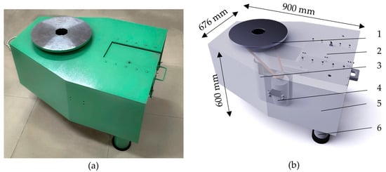
Figure 1.
Schematic diagram of the overall mechanism of the pottery wheel machine: (a) physical display diagram of the second-generation pottery wheel machine and (b) model diagram of the second-generation pottery wheel machine (1. pottery wheel mechanism, 2. pull mechanism, 3. lifting mechanism, 4. bearing mechanism, 5. power transmission mechanism, 6. pottery wheel machine shell).
- Potter’s Wheel Mechanism: This mechanism is equipped with an intelligent centralized positioning system and an automatic feeding system, greatly enhancing operational precision and convenience. These features enable users to easily achieve high-quality clay shaping.
- Lifting Mechanism: The lifting mechanism has flexible adjustment capabilities to ensure the equipment remains in optimal condition under various working conditions.
- Support Structure: Designed to ensure overall stability and safety, the support structure guarantees reliable operation during use.
- Feeding Mechanism: The feeding mechanism is designed for easy loading and storage of clay materials, effectively improving operational efficiency and cleanliness.
- Power Transmission System: Using advanced technology, this system provides efficient and stable power transmission, ensuring the stability and consistency of the clay shaping process.
- Casing: The casing not only offers essential safety protection but also combines esthetic appeal with user-friendly design, enhancing the user experience by making the control panel more intuitive and convenient.
As shown in Table 1, certain fundamental parameters between the traditional and new systems remain consistent. These parameters include the number of products per second, product rotation, power, voltage, and control speed. Both systems offer similar basic functionality and performance, providing users with a comparable foundational operational experience.

Table 1.
Common parameters of traditional institutions and new institutions.
In contrast, Table 2 highlights significant differences in several key areas between the traditional and new systems. The diameter of the turntable in the new system has increased to 38 cm, a substantial improvement over the traditional system’s 25–30 cm. The surface material of the machine body has been upgraded from high-temperature spray plastic to Q235 metal, enhancing durability. The weight has increased from 15 kg to 35 kg, which contributes to greater stability during operation.
Table 2.
Comparative analysis of detailed data between traditional institutions and new institutions.
Operationally, the new system incorporates automation improvements. The clay installation and initial positioning process has been automated, moving away from manual operation. Regarding clay quality, the new system features a dedicated feeding mechanism that ensures consistent clay mass for each forming operation, unlike the variations seen with manual loading in traditional systems. The size and volume of clay handled by the new system have also increased from approximately 419,760 mm3 to about 736,000 mm3.
2.2. Innovation Points in Institutional Design
2.2.1. Central Positioning Feeding
Traditional feeding methods are primarily relied upon for manual alignment, which is not only time-consuming and labor-intensive but also requires a high level of skill from the operator. Small errors during the manual positioning process can significantly impact the consistency and symmetry of the final product. Additionally, due to the involvement of human factors, prolonged repetitive operations can lead to operator fatigue, increasing the likelihood of errors and ultimately affecting product quality.
In contrast, an automatic alignment system is introduced by the innovative mechanism developed in this study, revolutionizing the central positioning process without compromising the pottery creation experience. High-precision sensors and advanced control algorithms are integrated into this system to ensure that the clay blank is consistently maintained in the optimal position. This approach not only significantly reduces positioning time but also greatly enhances accuracy and consistency. High-precision sensors can monitor minute displacements of the clay blank in real-time and automatically adjust its position through a closed-loop control system, effectively eliminating errors that may arise from manual operations. As shown in Figure 2, the schematic diagrams depict the central positioning of clay blanks: (a) Manual Positioning and (b) Automatic Mechanical Positioning.
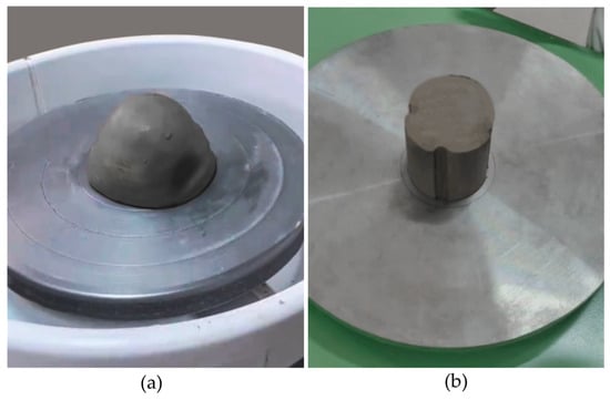
Figure 2.
Center positioning schematic of clay body: (a) manual positioning; (b) automatic machine positioning.
The automatic alignment system not only preserves the enjoyment of clay-forming but also significantly improves production efficiency and product quality. The workload of operators is reduced by the system, helping to mitigate occupational fatigue and associated risks. The ceramic manufacturing process is optimized by this innovative design, which also provides more precise and reliable technical support for pottery creation. It serves as a successful example of the integration of traditional craftsmanship with modern technology.
By streamlining the alignment process and ensuring consistent accuracy, the system enhances the overall productivity of ceramic workshops. Operators can focus more on the creative aspects of pottery without being bogged down by repetitive mechanical tasks. The reduction in manual interference also leads to fewer defects and a higher standard of final products, making the entire manufacturing process more efficient and cost-effective. This fusion of tradition and innovation has the potential to advance the field of ceramics, setting new benchmarks for both hobbyists and professional artisans alike.
The differences between traditional feeding methods and centralized positioning feeding methods are compared in this study, and their impact on the ceramic manufacturing process is investigated. Subsequent experimental results demonstrate that clay blanks using the centralized positioning feeding method exhibit higher regularity, uniformity, and stability during the forming process. This finding underscores the importance of centralized positioning as a crucial step in ensuring the symmetry and esthetic quality of the clay blanks.
2.2.2. Automatic Feeding System
The automatic feeding system developed in this study represents a significant innovation, greatly enhancing production efficiency and operational convenience while preserving the traditional enjoyment of pottery-making. In traditional feeding methods, operators must manually complete the feeding process, which not only consumes a considerable amount of time and effort but also risks damaging the clay blanks due to human error or oversight, leading to frustration and resource waste.
To address these issues, the new mechanism incorporates an advanced automatic feeding system. As shown in Figure 3, the diagrams depict the pulling mechanism: (a) actual system image and (b) schematic diagram of the pull mechanism model. The system employs a modular design composed of a clay storage outlet, power device, handle, partition, two sliding tracks, and two sliders. The clay storage and power device components are symmetrically positioned at the front and rear ends of the partition, each fulfilling specific functions: the former is responsible for storing and dispensing pre-stored clay materials, while the latter connects to the power system to ensure the accuracy of clay material dispensing. This design allows for the automatic, continuous, and smooth delivery of clay blanks to the work area. The core of the system lies in its precise control algorithms and real-time feedback mechanisms, ensuring the stability and reliability of the feeding process.
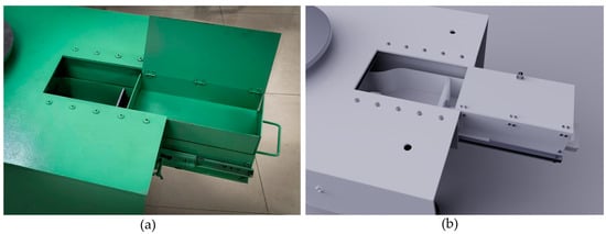
Figure 3.
Pulling Mechanism Diagram: (a) physical diagram of the pulling mechanism; (b) schematic diagram of the pull mechanism model.
The application of the automatic feeding system brings significant advantages. Efficiency is greatly improved, as indicated by the quantitative analysis showing that feeding time can be reduced by approximately 60% by the automatic feeding system compared to traditional methods. Additionally, the system minimizes clay blank damage caused by human error, effectively reducing raw material waste and increasing resource utilization. The system’s integrated data recording function can track the feeding time and quantity of each batch of clay blanks, providing reliable data support for quality control and production management.
It is worth emphasizing that in the design and implementation of the automatic feeding system, we paid special attention to preserving the traditional enjoyment of pottery-making. The system’s user interface is designed to be simple and intuitive, allowing users to easily switch to manual mode when desired. This ensures production efficiency while retaining the joys of handcrafted creation. The operational noise of the system is minimized, ensuring that the user’s creative process is not interfered with.
2.3. Code Implementation
This code aims to achieve the central positioning and automatic feeding functions of the pottery-forming process using MATLAB 2021a. Its core focus is on leveraging real-time sensor data to achieve precise positioning and quantification of the clay feed, thereby enhancing the automation and precision of pottery production. Regarding hardware interfaces, the code utilizes MATLAB’s hardware toolbox to configure communication with sensors and actuators, laying a foundation for real-time monitoring and control.
For sensor data processing and error correction, the program integrates a proportional controller to correct deviations in clay positioning in real-time, ensuring a quick response while reducing system instability. Filtering techniques are employed to minimize sensor signal noise, significantly improving data accuracy and reliability. To ensure system safety, boundary check mechanisms are incorporated, and an emergency stop function is implemented to effectively mitigate potential operational risks in case of anomalies. This is illustrated in Figure 4.
Figure 4.
Code running diagram.
Ultimately, by effectively integrating sensor interfaces and control algorithms, the code achieves accurate central positioning and feeding of clay in the pottery-forming process. The specific implementation of the code is as follows:
| classdef ClayFormingMachine properties CenterPosition = 0; ClayPosition = 0; IsClayCentered = false; SensorInterface % Placeholder for actual sensor interface end methods function obj = ClayFormingMachine(sensorInterface) obj.SensorInterface = sensorInterface; % Initialize sensors and actuators end function obj = moveToCenter(obj) disp(‘Moving clay to center…’); while ~obj.IsClayCentered try sensorValue = obj.readCenteringSensor(); catch disp(‘Error reading sensor’); return; end error = obj.CenterPosition − sensorValue; if abs(error) < 0.01 obj.IsClayCentered = true; disp(‘Clay is centered.’); else obj = obj.adjustPosition(error); pause(0.1); % Adjust pause for real-time responsiveness end end end function sensorValue = readCenteringSensor(obj) try sensorValue = obj.SensorInterface.readData(); % Real sensor data catch error(‘Sensor read failed’); end end function obj = adjustPosition(obj, error) Kp = 1.0; % Proportional gain for PID controller adjustment = Kp * error; fprintf(‘Adjusting position by %f units…\n’, adjustment); % Implement motor control logic % Send adjustment command to motor controller end function autoFeedClay(obj, desiredQuantity) fedClay = 0; while fedClay < desiredQuantity % Logic to feed clay fedClay = fedClay + obj.feedClayUnit(); disp(‘Feeding clay…’); end disp(‘Clay feeding complete.’); end function clayUnit = feedClayUnit(~) % Real clay feeding logic clayUnit = 10; % For example, feed 10 grams per action end if ~obj.IsClayCentered disp(‘Error: Clay is not centered.’); return; end disp(‘Starting the forming process…’); % Implement forming logic end end end |
3. Investigating the Patterns of Plastic Deformation in the Clay-Forming Process
3.1. Finite Element Model
To explore the plastic deformation behavior of clay during the forming process, a comprehensive three-dimensional finite element model was developed on the DEFORM-3D platform. This model effectively reflects the experimental setup by simulating the operator’s hands as the upper mold and utilizing two different comparative clay blanks produced by traditional and newly designed equipment. The clay blanks are positioned on a modeled lower mold, representing the base.
In the simulation, the upper mold, emulating hand movements during the clay-forming process, rotates around its axis, delivering rotational loading to the clay. Concurrently, the lower mold performs a feeding motion, applying feeding loading, which mirrors the mechanical behavior of clay in actual hand-forming scenarios. These dynamic interactions between the molds and the clay enable the model to replicate real-world forming conditions.
By implementing this setup, the model allows an in-depth analysis of plastic deformation patterns under various operating conditions. This reflection of real-world settings enables us to optimize forming processes and equipment design, ultimately enhancing the quality and production efficiency of ceramic products. The simulation results highlight the differences in clay behavior due to variations in equipment design, with Figure 5 presenting the outcomes for the two comparative groups: Figure 5a clay optimized by the new equipment and Figure 5b clay from traditional equipment.
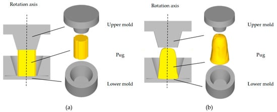
Figure 5.
(a) Clay optimized by the new equipment; (b) clay from traditional equipment.
The upper mold operates with dual-motion dynamics, rotating at 25.12 rad/s and revolving at −25.12 rad/s, ensuring alignment with the clay contour and efficient shaping. Simultaneously, the lower mold contributes through axial feeding at 4 mm/s. The clay billet, serving as the primary subject of the simulation, possesses elastic–plastic material properties with stress–strain behavior illustrated in Figure 6. In Figure 6, the true strain and true stress represent the strain and stress that account for changes in material length and cross-sectional area during deformation. True strain and true stress offer a more accurate description of material mechanical behavior under deformation conditions, providing a basis for material settings in subsequent simulation experiments.
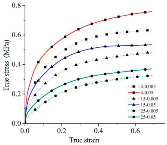
Figure 6.
Real stress and strain maps of clay materials.
As shown in Table 3, black clay material is widely used due to its excellent properties and is considered outstanding when creating works with intricate details, especially in wheel throwing and sculpting. The ideal firing temperature range is set between 1240 and 1280 °C, with the firing range defined as 1000–1350 °C to ensure stability under various processing conditions. The clay is described as black in its wet state and white in its dry state, with its main components identified as quartz, kaolin, hematite, and calcite, which give it high plasticity and fine to medium particle size. The drying time is typically estimated at 1–3 days, depending on environmental conditions, and for this experiment, the black clay used in wheel throwing was observed to turn white and dry approximately 2 days after handling.
Table 3.
Use clay parameters.
In the study, black clay material exhibits excellent adaptability and maintains relatively stable performance in the throwing process. The pre-forming blank production conducted with the equipment provided by the experiment showed uniformity in the blanks. The technology employed by this equipment focuses on shaping pre-clay blanks, aiming to save time on centering during subsequent throwing operations. Its pulling and lifting mechanisms’ thrust system is designed to divide the clay into uniform cylindrical forms and accurately lift them to the center of the platform. This technology not only enhances production efficiency but also ensures the consistency of the finished products, making it suitable for most medium-soft throwing clays.
The billet is discretized into 150,000 tetrahedral elements with a 3:1 mesh ratio to ensure detail in high-deformation areas. A finer mesh of 100,000 elements is applied to the upper mold due to its intricate movement, while the simpler die structure is represented with 60,000 elements.
All simulations are conducted at a stable room temperature of 20 °C, reflecting real-world cold forming processes. The H13 mold material is chosen for its mechanical properties, with thermal conductivity set at 11 W/(m·K). Contact between the clay material and the mold is modeled using sliding friction with a constant friction factor of 0.3, simulating realistic conditions.
The parameters detailed in Table 4 underscore the robustness and fidelity of the model in replicating physical scenarios. Precise calibration of speed, mesh granularity, and material attributes ensures the simulation’s reliability in predicting realistic outcomes. This comprehensive computational setup supports the model’s validity and applicability in studying clay-forming processes.
Table 4.
Finite element simulation parameters for clay-forming.
This meticulously designed setup ensures that real-world conditions are closely replicated in the simulation, with the intricate nuances of material behavior and interaction under load being captured. By accurately modeling the distinct properties and interactions between the elastoplastic clay and the rigid mold, precise predictions of the forming outcomes are provided. These insights are used to facilitate the optimization of both the forming process and equipment design, ultimately leading to enhanced production efficiency and product quality in ceramic manufacturing.
The anticipated simulation results, depicted in Figure 7b, show how the two types of clay blanks shown in Figure 7a can be processed into a simple tapered bottle. The effectiveness of the forming process in achieving the desired shape is underscored by this illustration, with the differences between traditionally prepared clay and clay optimized through the new equipment being highlighted. Valuable insights into the flow and deformation behaviors of the clay material under various conditions are offered by the simulation results, allowing for the refinement of forming parameters for optimal performance.
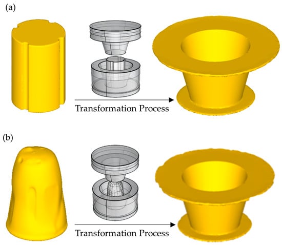
Figure 7.
Expected results of clay simulation: (a) expected outcomes of new clay; (b) expected outcomes of traditional clay.
By comparing the two types of clay blanks, we can evaluate the efficiency and quality of the forming process, ensuring that the final product meets the required standards. This analysis not only helps in perfecting the design of forming equipment but also contributes to the advancement of ceramic manufacturing techniques, bridging the gap between traditional craftsmanship and modern technology.
3.2. Equivalent Stress Distribution and Evolution Law
Figure 8 presents the equivalent stress contour plots for the clay simulation: Figure 8a–c optimized through our new equipment, and Figure 8d–f using traditional forming methods. From this figure, it can be observed that, due to the localized contact between the upper mold and the clay during the forming process, the equivalent stress within the contact zones is significantly higher than in the non-contact zones. The contact areas are predominantly concentrated in the central region, resulting in the equivalent stress being higher in the bottom area of the bottle compared to the wall region.
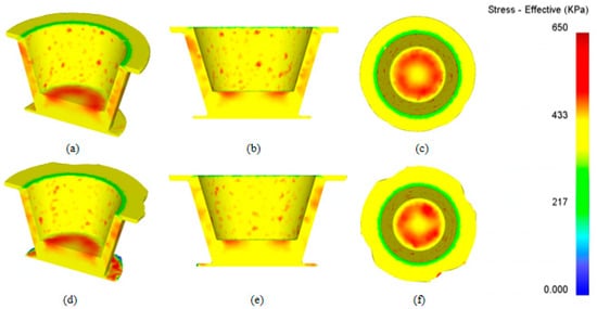
Figure 8.
Equivalent force cloud map. (a) Represents an oblique half-screenshot of the simulation results using the new clay molding equipment. (b) Represents a frontal half-screenshot of the simulation results using the new clay molding equipment. (c) Represents a top view of the simulation results using the new clay molding equipment. (d) Represents an oblique half-screenshot of the simulation results using the original clay molding equipment. (e) Represents a frontal half-screenshot of the simulation results using the original clay molding equipment. (f) Represents a top view of the simulation results using the original clay molding equipment.
The stress concentrations appear in the specified regions due to the localized contact between the upper mold and the clay during the forming process. This contact results in higher equivalent stress within the contact zones compared to the non-contact zones. Specifically, the bottom area of the bottle experiences higher stress because the clay is pressed and flows into the wall region, leading to intense shear deformation at the corner where the bottom transitions to the wall. This transition area exhibits the highest equivalent stress due to the combined effects of compression and material flow.
These observations underscore the crucial roles of localized stress distribution and material flow in determining the quality of the formed product. Understanding these stress patterns and deformation behaviors allows for targeted improvements in both the material properties and the design of forming equipment, thereby enhancing the overall efficiency and quality of the ceramic manufacturing process.
By comparing the stress distributions between the optimized and traditional methods, we can gain insights into the advantages of our new equipment. These insights facilitate the refinement of forming techniques and the development of more robust equipment, ultimately leading to superior ceramic products that meet higher quality standards.
The mechanical properties of clay, such as compressive strength, tensile strength, and shear resistance, are critical factors in determining the quality and durability of ceramic products. These properties are significantly influenced by our new feeding system, which is characterized by its central positioning and automated feeding capabilities. Through central positioning, uniform distribution of clay within the mold is ensured, stress concentrations are minimized, and even material flow is promoted. As a result, the compressive strength of the clay is enhanced by reducing weak points that could lead to structural failures. Additionally, consistent and precise control over the amount of clay introduced into the mold is provided by the automated feeding system, optimizing the tensile strength by ensuring that the clay is neither too dense nor too sparse. Shear resistance is also improved by maintaining a consistent clay composition throughout the forming process. By integrating these features, the mechanical properties of the clay are enhanced, and a more efficient and reliable forming process is contributed to, resulting in higher quality ceramic products.
The equivalent stress contour plots primarily reflect the difficulty of plastic deformation at different locations during the clay-forming process, but they do not fully reveal the stress state of the clay. To more specifically illustrate the stress state during clay-forming, we will examine the distribution patterns of stress in three directions: radial, lateral, and axial. Figure 9 presents the directional stress distribution plots for the clay simulations, with (a) showing the results optimized through our new equipment and (b) illustrating those from traditional forming methods.
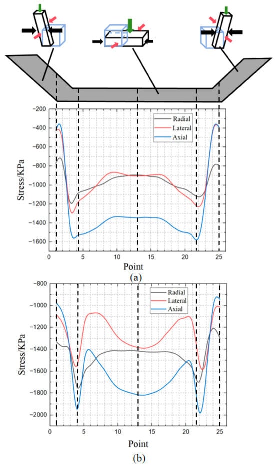
Figure 9.
Simulation of stress distribution in all directions of clay material. (a) Represents the simulation of the three-directional stress distribution results using the new clay molding equipment. (b) Represents the simulation of the three-directional stress distribution results using the original clay molding equipment.
In the 3D-post module of the DEFORM software, execute a section cut on the bottom surface of the formed cup-shaped billet. On the resulting cutting plane, draw a line segment along the X-axis that passes through the origin of the bottom surface, incorporating 25 data monitoring points. Subsequently, by adjusting the stress direction variables, calculations are performed and the stress values in various directions.
By analyzing these plots, we can gain a deeper understanding of the stress states at various positions within the clay during the forming process. Such detailed examination allows us to identify specific areas subjected to high stress concentrations and potential deformities. This information is crucial for optimizing the forming parameters and improving the design of the equipment to ensure better product quality and consistency.
Comparing the directional stress distributions between the optimized and traditional methods further highlights the benefits of using the newly designed equipment. A robust framework for enhancing manufacturing processes and achieving superior end products is provided by these insights, which are instrumental in advancing ceramic forming techniques.
3.2.1. Radial Stress
In the forming method using the optimized equipment, the radial stress distribution is relatively smooth and uniform, with the central region maintaining a radial stress of approximately −900 kPa, indicating a significant reduction in stress concentration. This even stress distribution enhances the stability of the forming process and reduces the likelihood of cracks or defects caused by stress concentrations.
In contrast, the traditional forming method exhibits pronounced fluctuations in radial stress, with the central region showing stress values around −1400 kPa. Additionally, stress concentrations are observed at both ends of the formed product, which could increase the risk of material failure.
The optimized equipment effectively reduces end-region stress concentrations, thereby significantly improving the structural integrity and longevity of the product. This reduction in stress concentration not only ensures a more stable forming process but also enhances the overall quality and durability of the ceramic items produced.
3.2.2. Lateral Stress
In the forming method using the optimized equipment, the lateral stress distribution is more uniform and stable, with the central region’s lateral stress values around −800 kPa. This uniform distribution helps to minimize local stress peaks caused by stress concentrations, thereby reducing the risk of material cracks and structural defects due to uneven stress distribution.
In contrast, the traditional forming method exhibits noticeable fluctuations in lateral stress, with significant stress variations in the central region. Such fluctuations can easily lead to local stress concentrations, potentially causing a decline in the mechanical performance of the final product and even early failure. Additionally, the traditional forming method shows higher stress concentrations at the ends, further increasing the likelihood of material failure.
By significantly improving the lateral stress distribution, the optimized equipment effectively enhances the uniformity of the forming process and the quality of the product. This improvement ensures the structural integrity and durability of the final product, making it more reliable and long-lasting.
3.2.3. Axial Stress
In the forming process implemented with the optimized equipment, the axial stress distribution is notably more uniform, especially in the central region where the axial stress remains around −1400 kPa. This stable stress distribution helps to minimize material cracks and structural defects caused by stress concentrations, thus enhancing the uniformity and reliability of the material during the forming process. Moreover, the optimized equipment significantly reduces stress concentrations at the ends of the formed product, further improving the structural integrity and longevity of the final product.
In contrast, the traditional forming method exhibits considerable fluctuations in axial stress, with the central region showing significant stress variations, typically forming an arc-shaped distribution. This stress non-uniformity can easily lead to local stress concentrations, thereby resulting in cracks or other defects during the forming process and increasing the risk of product failure. Additionally, the traditional forming method demonstrates higher stress concentrations at the ends, contributing to a decline in structural integrity and lifespan.
Overall, the optimized equipment significantly improves the distribution of radial, circumferential and axial stresses, enhancing the uniformity and stability of the clay-forming process. The mechanical performance and structural reliability of the final product are effectively boosted by this improvement. Equipment optimization plays a crucial role in improving the quality of clay-forming and extending the product’s lifespan. It is illustrated by these findings that more stable stress distributions can be achieved through equipment optimization, significantly enhancing the performance and quality of the clay-forming process.
3.3. Distribution and Evolution Law of Equivalent Effect Variation
To illustrate the varying degrees of plastic deformation in different areas of the cup bottom and wall during the clay-forming process, this section examines the distribution and evolution of equivalent strain, as depicted in Figure 10.
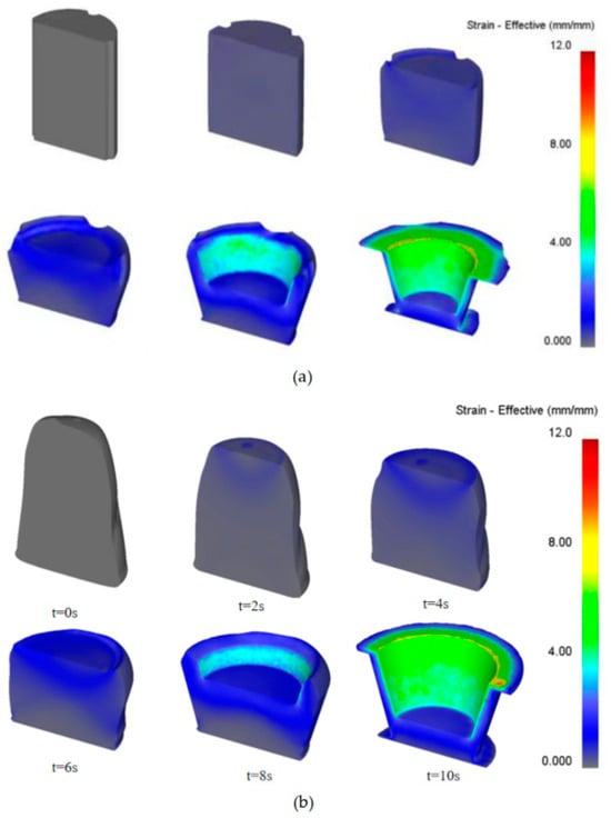
Figure 10.
Equivalent effect changed cloud map. (a) Represents the strain distribution cloud map from an oblique half-screenshot using the new clay molding equipment. (b) Represents the strain distribution cloud map from an oblique half-screenshot using the original clay molding equipment.
The first set of images in Figure 10a show the equivalent strain distribution at different stages of the forming process. Initially, the strain is concentrated at the bottom center of the cup, where the mold first contacts the clay. As the process progresses, the strain spreads towards the edges of the bottom and up the cup wall. This distribution indicates that the clay at the bottom edge undergoes plastic deformation for a longer period before flowing into the wall area, resulting in more accumulated plastic deformation. The images also highlight an increased strain at the transition corner between the bottom and the wall, where shear forces are most intense.
The second set of images in Figure 10b provide a time-lapse view of the equivalent strain evolution during the forming process. Starting from t = 0 s, the strain is initially low but increases significantly as the process continues. By t = 10 s, the strain is highest at the bottom edge and the transition corner, reflecting the intense shear deformation and material flow in these areas. The images also show that the equivalent strain is not uniform on either side of the cup wall, attributed to the asymmetric volume of clay flowing into the cup wall area from either side’s mesh elements, causing a differential accumulation of plastic strain.
From this figure, it is evident that the equivalent strain exhibits a gradual increase from the top of the cup wall to the base. This trend occurs because the clay closer to the bottom edge of the cup wall undergoes plastic deformation for a longer period before flowing into the wall area, resulting in more accumulated plastic deformation. Additionally, within the bottom area, the equivalent strain generally increases from the center to the edge. This pattern occurs because the tangential line speed of the oscillating mold is greater towards the edge of the bottom plate, leading to more intense tangential flow and, subsequently, more severe plastic deformation. Furthermore, the equivalent strain in the cup wall area is significantly greater than that in the bottom area. This is due to the clay transitioning from the bottom to the wall area, which must pass through the corner, where it undergoes intense shear deformation, leading to increased accumulated plastic deformation. Due to the severe shear deformation at the corner, the equivalent strain peaks in this region. Moreover, the equivalent strain is not uniform on either side of the cup wall, due to the asymmetric volume of clay flowing into the cup wall area from either side’s mesh elements, causing a differential accumulation of plastic strain. This unequal deformation highlights the importance of understanding specific regional stress and strain behaviors to optimize the forming process, ensuring improved structural stability and quality of the final product.
Figure 11 illustrates that during the clay-forming process, significant strain values are observed in both the radial and axial directions, particularly in the cup wall region. This indicates that the clay undergoes substantial plastic deformation along these two axes. Conversely, the lateral strain is relatively minor, suggesting that deformation in this direction is more uniform and stable. By comparing these three types of strains, we can gain a clearer understanding of the deformation behavior of the clay throughout the forming process.
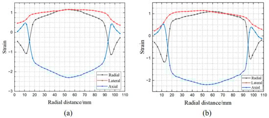
Figure 11.
Simulation of strain distribution in various directions of clay materials. (a) Represents the simulation of the three-directional strain distribution results using the new clay molding equipment. (b) Represents the simulation of the three-directional strain distribution results using the original clay molding equipment.
Figure 11 presents strain distribution plots for two distinct forming methods, labeled as Figure 11a,b. While both figures share consistency in radial distance (0 to 110 mm) and strain range (−3 to 3), they exhibit significant differences in strain distribution. In Figure 11a, the radial and axial strains display more pronounced peaks and troughs around radial distances of approximately 20 mm and 90 mm, indicating higher stress concentrations at these positions. Additionally, the transverse strain in Figure 11a demonstrates more noticeable fluctuations compared to Figure 11b. These distinct strain features suggest that the method represented in Figure 11a is superior in revealing areas of stress concentration within the material.
Through the comparative analysis of the strain distributions from the two forming methods, we find that the strain characteristics in Figure 11a are more pronounced and of greater magnitude, highlighting differences in stress concentration locations. This insight provides a foundation for the further optimization of processing parameters and equipment design, aiming to reduce defects and inconsistencies during forming. Therefore, selecting a more advantageous process path and equipment configuration can have a positive impact on improving the quality and consistency of ceramic products, advancing ceramic forming technologies.
3.4. Distribution and Evolution of Forming Flow Lines
The raw materials used for clay-forming consist of a mixture of kaolin, terracotta, quartz sand, and feldspar, along with additives such as plasticizers, petalite, and manganese oxide. This composition results in lateral forming streamlines within the clay body due to deformation. During the axial-forming process, these streamlines shift with the flow of the clay, ultimately forming specific patterns within the thin-walled cup structure. The distribution of these forming streamlines significantly impacts the mechanical properties of the thin-walled components. Therefore, this study employs finite element simulation to investigate the distribution and evolution of forming streamlines during clay-forming.
Initially, lateral forming streamlines are designed within the clay. As axial loading is applied to the upper mold, the clay begins to flow into the cup wall cavity. This movement alters the forming streamlines in the base plate due to the dynamic flow of material. Figure 12 illustrates the evolution of forming streamlines during this process. The figure clearly shows that the most significant changes occur in the cup wall region, where the forming streamlines shift noticeably along the axial direction, with increased spacing between them. This indicates substantial tensile deformation in this area. Additionally, throughout the axial forming process, the forming streamlines remain continuous and parallel to the contour of the cup wall, maintaining a consistent distribution that conforms to the shape of the wall.
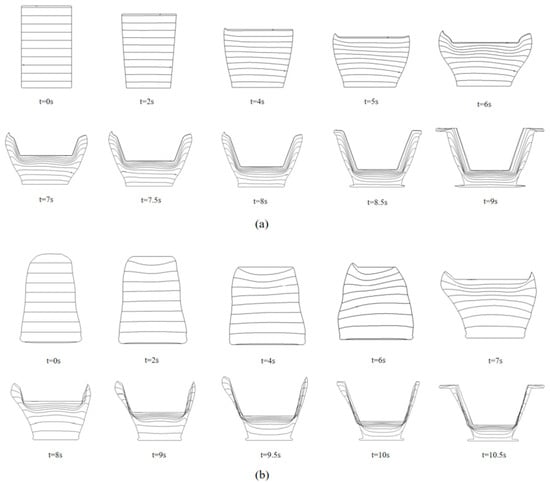
Figure 12.
Distribution and evolution diagram of forming streamline. (a) Represents the clay molding streamlines from the simulation results using the new clay molding equipment. (b) Represents the clay molding streamlines from the simulation results using the original clay molding equipment.
The two figures show marked differences in several key aspects of the streamline presentation. Figure 12a features clearer and more uniform streamline distributions, effectively illustrating the flow paths and transitions of the clay during forming. It exhibits a higher density of streamlines, allowing for the detailed capture of subtle changes and movement within the clay matrix. Additionally, the streamline evolution in Figure 12a is smoother, with distinct changes over time, accurately reflecting the dynamics of the forming process. In contrast, Figure 12b has less distinct and sparser streamlines, making it challenging to discern intricate flow details and transitions accurately.
During the axial rotation, the clay demonstrates notable radial flow, facilitating easier movement from the central base towards the edges. Consequently, the clay in the inner cup wall region originates primarily from central grid elements, leading the forming streamlines in this area to exhibit an outward shift. The continuity of these forming streamlines along the shape of the cup wall effectively enhances the structural strength and toughness of the wall, thereby significantly improving the load-bearing capacity and firing quality of the thin-walled ceramic cups.
3.5. Variation Law of Forming Load
Figure 13 shows the load curve during the clay-forming process, divided into two phases: the forming phase and the finishing phase. In the forming phase, the load curves for all molds generally increase, with the rate of increase accelerating over time. This trend results from the expanding contact area between the molds and the clay as the upper mold rotates and the lower mold advances, causing more clay to undergo plastic deformation.
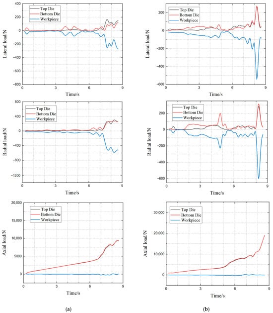
Figure 13.
Three directional forming force during clay-forming process.
Through a quantitative analysis of Figure 13, comparing the left side Figure 13a and the right side Figure 13b, we can clearly conclude that the performance of Figure 13a is significantly superior to that of Figure 13b. In terms of lateral load, the maximum fluctuation range of Figure 13a is approximately −300 kN to 200 kN, with a span of about 500 kN, which is noticeably smaller than Figure 13b’s range of −600 kN to 400 kN, totaling around 1000 kN. This indicates that the processing in Figure 13a provides greater stability regarding lateral forces.
For the radial load analysis, while the total fluctuation span in Figure 13b is slightly smaller (about 1000 kN), the curve in Figure 13a is distinctly smoother, with a maximum fluctuation range of −800 kN to 400 kN, totaling approximately 1200 kN. The absence of sharp fluctuations present in Figure 13b reflects better dynamic control in Figure 13a.
The axial load comparison further supports this conclusion. In Figure 13a, the maximum axial load is about 10,000 kN, and the growth of the curve is steady. Conversely, in Figure 13b, the maximum value approaches 20,000 kN, with a sharp rise in the latter stages, indicating greater instability. The notably lower and smoother growth curve of axial loads in Figure 13a suggests a more controllable and stable processing procedure.
Regarding curve smoothness, all mechanical curves in Figure 13a are smoother than those in Figure 13b, with no sudden spikes or troughs, affirming the stability of the processing in Figure 13a. Additionally, the workpiece force curve in Figure 13a shows minimal fluctuations, remaining near zero, while significant fluctuations are observed in Figure 13b, indicating a more uniform stress distribution in Figure 13a, contributing to enhanced product quality.
Therefore, upon assessing lateral, radial, and axial loads and workpiece curve analyses, the configuration on the left Figure 13a surpasses the right Figure 13b in terms of force control, process stability, and controllability. This suggests that Figure 13a not only ensures a more uniform stress distribution but also possesses a significant advantage in maintaining product quality, as shown in Figure 13 specifically:
In contrast, the finishing phase shows a decreasing trend in the load curves. Here, the upper mold continues to rotate while the lower mold stops advancing, reducing the contact area and decreasing the amount of clay experiencing plastic deformation. This figure indicates that the lower mold primarily bears axial loads, while the upper mold handles radial loads. Axial loads on the lower and upper molds are equal in magnitude but opposite in direction, balancing each other. Radial loads on the lower and upper molds sum to equal the radial load on the clay, directed away from the center of the cross-shaped ring, ensuring equilibrium. Frictional forces between the clay and molds result in circumferential loads on both. The circumferential load directions on the molds are identical but oppose the clay’s load direction. The sum of the circumferential loads on the molds equals the clay’s circumferential load, achieving equilibrium.
3.6. Vickers Hardness Test
The Vickers hardness test is conducted using a diamond pyramid indenter with a square base and an angle of 136 degrees between opposite faces.
When the indenter is pressed into the material under a specified load, the resulting indentation’s diagonals, D1 and D2, are measured. These measurements are utilized to calculate the Vickers hardness number (HV) with the following equation:
where:
To simplify calculations, the measurement time is assumed to be 15 s, and the applied force is assumed to be 200 N. F represents the applied force in kilograms-force (kgf), D denotes the average length of the two diagonals in millimeters (mm).
Baseline hardness data were obtained under normal conditions without any enhanced processing applied. These measurements serve as a reference for evaluating the effects of central positioning and automated feeding enhancements. The data are shown in Table 5:
Table 5.
Normally measured data.
Through the application of central positioning and automated feeding, significant improvements in Vickers hardness values were observed, with an increase of approximately 30% compared to normal conditions. The data are shown in Table 6:
Table 6.
The data measured after processing by the device.
A pronounced enhancement in hardness was achieved through the process of central positioning and automated feeding. The Vickers hardness increased by approximately 30%, illustrating that the method effectively improves the uniformity and consistency of material properties. Consequently, products exhibit superior mechanical stability and quality.
4. Mud Forming Verification Test
4.1. Mold Frame Design and Manufacturing
To validate the effectiveness of the proposed clay-forming principles and process design methodology, we conducted a clay-forming experiment. The equipment used in this experiment features a movable platform capable of axial rotation thanks to a parallel linkage drive system. Additionally, this platform can perform feed movements along the axial direction when pushed collectively by the linkages, while the lower platform remains stationary.
The upper mold is mounted on the movable platform, and the lower mold is secured on the stationary lower platform. The structural setup of the clay-forming molds is illustrated in Figure 14. The molds are made from H13 tool steel, with both upper and lower molds machined using high-speed milling. To minimize frictional resistance between the clay and the molds, both mold cavities are polished, which reduces forming loads and enhances the filling of the thin-walled cup features.
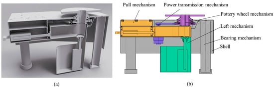
Figure 14.
Diagram of the plan surface of the pottery wheel machine: (a) model diagram of the plan surface of the pottery wheel machine; (b) engineering diagram of the plan surface of the pottery wheel machine.
The cavity of the upper mold incorporates a draft angle to reduce demolding forces necessary to remove the molded piece. In contrast, the lower mold cavity lacks a draft angle, ensuring that once the upper mold retracts after forming, the thin-walled cup piece remains within the lower mold. The demolding process is simplified by this setup, ensuring easier extraction of the formed piece.
4.2. Experiment Scheme
The main process parameters of the clay-forming test are consistent with those of the finite element simulation, and the test process includes the following steps:
- Raw material storage: Load the pre-treated clay material into the clay storage section of the automatic feeding system to ensure sufficient clay volume in the silo.
- Feeding start: Start the power device and smoothly deliver the clay material to the forming worktable through the slider and slide rail system. This process is monitored in real-time by sensors.
- Feeding: The system precisely controls the feeding speed and quantity of clay materials based on the set process parameters.
- Filling stage: The clay material is evenly distributed to the feed inlet of the mold or machine.
- Pressing or casting stage: Under a set pressure and speed, clay material is pressed or cast into a rough shape.
- Adjustment stage: Through the meticulous adjustment and shaping of the robotic arm, the clay embryo gradually approaches the final design form.
- Forming completion: The formed clay embryo is transported to the next process (such as drying, firing, etc.) while the automatic feeding system continues to feed for the next forming cycle.
- Data recording and analysis: Through an integrated data recording device, parameters such as feeding time, feeding amount, and forming pressure of each batch of clay embryos are recorded, providing data support for subsequent quality control and performance analysis.
4.3. Equipment Innovation
The traditional pottery wheel is a device used for handcrafting pottery, typically consisting of a rotating turntable and a drive mechanism. The workflow involves preparing the clay and placing it at the center of the turntable, then starting the rotation and manually adjusting the speed and direction to shape the clay. Key challenges include ensuring the initial placement of the clay and its initial quality, often leading to issues such as uneven force distribution, irregular shapes, and incorrect positioning. To address these challenges, the development of the new equipment focuses primarily on the preliminary steps of the forming operation, aiming to optimize the quality of the clay before the shaping process begins.
As shown in Figure 15, the six key steps for using the equipment are displayed sequentially. The process begins by opening the device’s pulling mechanism to access the internal components. Once opened, clay is loaded into the designated area and pushed forward, ensuring even force distribution until it reaches the specified positioning area. Positioning the clay at the center of the pottery wheel mechanism is crucial for achieving balanced and symmetrical pottery formation. Next, the lifting mechanism is activated to raise the clay to the working platform, preparing it for the throwing operation. The user manually performs the throwing operation, using traditional pottery techniques to shape the clay into the desired piece, showcasing the pottery work created by novice users.
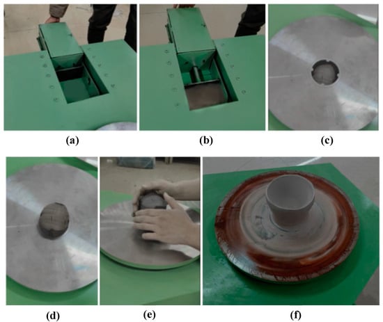
Figure 15.
Schematic diagram of the equipment usage process: (a) pull open the equipment’s pulling mechanism; (b) load the clay and push it forward; (c) position the clay at the center of the pottery wheel mechanism; (d) the lifting mechanism raises the clay to the platform; (e) manually perform the throwing operation; (f) diagram of the formed pottery piece.
4.4. Actual Impact
Through automation and precise centering technology, production time is significantly reduced. The traditional manual positioning and adjustment processes are often time-consuming and prone to errors. The implementation of new technology greatly decreases the time spent on preparatory steps before the forming operation, primarily by reducing rework and material waste caused by human error, thus lowering overall production costs.
The equipment enhances the clay’s properties before the forming operation, particularly in terms of uniformity in appearance and internal density. With uniformly prepared clay and precise centering, even individuals with limited experience in this craft can easily operate the system. This reduces the extensive preparation time, and the high level of skill and experience previously required for accurate positioning techniques.
The clay is evenly distributed and shaped, minimizing the risk of stress concentration and structural defects. This results in smoother operations for users, with the clay being less prone to damage or inconsistencies. Consequently, the success rate of the final formed pieces is improved, enhancing the mechanical performance and durability of the finished products.
5. Conclusions
This study proposes and validates the feasibility and efficacy of an automated feeding system in the ceramic clay-forming process with the following key innovations:
- Automated Feeding Mechanism: The advanced automated feeding system developed is capable of supplying clay steadily and continuously under set process parameters. This results in a 30% increase in Vickers hardness, significantly enhancing the mechanical properties of the clay bodies. The improvement in process smoothness and efficiency reduces the need for manual intervention, making the production process more efficient and reliable.
- Real-time Monitoring and Data Logging: Precision sensors and data logging equipment were utilized to monitor critical data in real time, such as feed rate, clay moisture, and forming pressure. This real-time monitoring provides reliable data support for process optimization and ensures process control, allowing operators to adjust parameters promptly and avert potential production issues.
- Improved Product Consistency: The automated feeding method results in clay bodies with high consistency across various trials. This innovation effectively reduces errors introduced by manual operations, thereby enhancing the quality of the final product. High consistency not only increases product competitiveness in the market but also reinforces consumer confidence.
- Reduced Material Waste: The precise control facilitated by the system minimizes material waste and optimizes resource utilization. This promotes sustainable production practices while reducing production costs, providing economic benefits to the enterprise.
- Adaptability and Flexibility: The system can be adjusted according to different process parameters, accommodating various forming needs. This flexibility allows ceramic manufacturing to better respond to market changes and customer demands, enhancing production adaptability and responsiveness.
- Integration of Traditional Craft and Modern Technology: This study offers a new perspective on modernizing ceramic forming technology by successfully integrating traditional craftsmanship with modern automation. This amalgamation retains the artistic and artisanal aspects of traditional ceramic production while introducing the efficiency and precision of modern technology, paving a new direction for the field’s development.
Based on the results of this study, future research could begin with an in-depth exploration of the mechanical properties of ceramic clay, serving as a foundation for further advancements. This could include optimizing automated systems through AI and machine learning to enhance predictive capabilities and process improvements. Additionally, examining the scalability of these systems for various ceramic production scales and types, along with incorporating sustainable practices to reduce environmental impact, would be advantageous. Developing user-friendly interfaces and training modules could also make these advanced systems more accessible to beginners, facilitating easier adoption and skill development. These directions promise to propel the ceramic manufacturing industry towards greater efficiency, adaptability, sustainability, and inclusivity for new users.
Author Contributions
Investigation, methodology and writing—original draft preparation, X.L.; investigation, methodology and writing—original draft preparation, Y.W.; Investigation and methodology, B.M.; investigation, H.W.; supervision, writing—review and editing, L.W.; supervision, writing—review and editing, M.C.; investigation, S.G. All authors have read and agreed to the published version of the manuscript.
Funding
This work is supported by the Postdoctoral Fellowship Program of CPSF (No. GZC20232015), the China Postdoctoral Science Foundation (No. 2024M752499), 2021 Hubei Provincial Philosophy and Social Science General Project (grant number: 21Y085).
Institutional Review Board Statement
Not applicable.
Informed Consent Statement
Not applicable.
Data Availability Statement
The original contributions presented in the study are included in the article, further inquiries can be directed to the corresponding author.
Conflicts of Interest
The authors declare no conflict of interest.
References
- Erdogmus, E.; Sutcu, M.; Hossain, S.; Bayram, M.; Sarı, A.; Gencel, O.; Ozbakkaloglu, T. Effect of molding pressure and firing temperature on the properties of ceramics from natural zeolite. Constr. Build. Mater. 2023, 402, 132960. [Google Scholar] [CrossRef]
- La Noce, M.; Lo Faro, A.; Sciuto, G. Clay-based products sustainable development: Some applications. Sustainability 2021, 13, 1364. [Google Scholar] [CrossRef]
- Vasconcelos da Silva, A.M.; Delgado, J.M.P.Q.; Guimarães, A.S.; Barbosa de Lima, W.M.P.; Soares Gomez, R.; Pereira de Farias, R.; Santana de Lima, E.; Barbosa de Lima, A.G. Industrial ceramic blocks for buildings: Clay characterization and drying experimental study. Energies 2020, 13, 2834. [Google Scholar] [CrossRef]
- Vakalova, T.V.; Revva, I.B. Highly porous building ceramics based on «clay-ash microspheres» and «zeolite-ash microspheres» mixtures. Constr. Build. Mater. 2022, 317, 125922. [Google Scholar] [CrossRef]
- Nikkilä, L. Designing for Manufacturing on a Desktop FDM 3D Printer: Designing a 3D Printable DIY Ceramics Extruder. Bachelor’s Thesis, Metropolia University of Applied Sciences, Metropolia, Finland, 2024. [Google Scholar]
- Rognoli, V.; Ayala-Garcia, C. Defining the DIY-Materials Approach. In Materials Experience 2; Butterworth-Heinemann: Oxford, UK, 2021; pp. 227–258. [Google Scholar]
- Rognoli, V.; Ayala-Garcia, C.; Pollini, B. DIY Recipes: Ingredients, processes & materials qualities. In Materials Designers. Boosting Talent towards Circular Economies; Clèries, L., Rognoli., V., Solanki., S., Llorach., P., Eds.; Elisava Barcelona School of Design and Engineering: Barcelona, Spain, 2021; pp. 27–33. [Google Scholar]
- Yu, F.; Deng, H.; Bai, H.; Zhang, Q.; Wang, K.; Chen, F.; Fu, Q. Confine clay in an alternating multilayered structure through injection molding: A simple and efficient route to improve barrier performance of polymeric materials. ACS Appl. Mater. Interfaces 2015, 7, 10178–10189. [Google Scholar] [CrossRef]
- Manikandan, K.; Jiang, X.; Singh, A.A.; Li, B.; Qin, H. Effects of nozzle geometries on 3D printing of clay constructs: Quantifying contour deviation and mechanical properties. Procedia Manuf. 2020, 48, 678–683. [Google Scholar] [CrossRef]
- Nicolas, M.F.; Vlasova, M.; Aguilar, P.A.M.; Kakazey, M.; Cano, M.M.C.; Matus, R.A.; Puig, T.P. Development of an energy-saving technology for sintering of bricks from high-siliceous clay by the plastic molding method. Constr. Build. Mater. 2020, 242, 118142. [Google Scholar] [CrossRef]
- Ahmad, M.; Rashid, K. Novel approach to synthesize clay-based geopolymer brick: Optimizing molding pressure and precursors’ proportioning. Constr. Build. Mater. 2022, 322, 126472. [Google Scholar] [CrossRef]
- Cabalar, A.F.; Demir, S.; Khalaf, M.M. Liquefaction resistance of different size/shape sand-clay mixtures using a pair of bender element–mounted molds. J. Test. Eval. 2021, 49, 509–524. [Google Scholar] [CrossRef]
- Baldovino, J.D.J.A.; Izzo, R.L.D.S.; Feltrim, F.; da Silva, É.R. Experimental study on guabirotuba’s soil stabilization using extreme molding conditions. Geotech. Geol. Eng. 2020, 38, 2591–2607. [Google Scholar] [CrossRef]
- Junior, J.A.L.; de Azevedo, A.R.G.; Marvila, M.T.; Teixeira, S.R.; Fediuk, R.; Vieira, C.M.F. Influence of processing parameters variation on the development of geopolymeric ceramic blocks with calcined kaolinite clay. Case Stud. Constr. Mater. 2022, 16, e00897. [Google Scholar] [CrossRef]
- Scheuermann Filho, H.C.; Beck Saldanha, R.; Gravina da Rocha, C.; Cesar Consoli, N. Sustainable binders stabilizing dispersive clay. J. Mater. Civ. Eng. 2021, 33, 06020026. [Google Scholar] [CrossRef]
- Akisanmi, P.; Akisanmi, P. Classification of clay minerals. In Mineralogy; BoD—Books on Demand: Norderstedt, Germany, 2022; pp. 3–9. [Google Scholar]
- Agarwal, K.; Folden-Ecker, A. Reducing Molding Sand Variation at a Job Shop Casting Facility. In Proceedings of the Second Australian International Conference on Industrial Engineering and Operations Management, Melbourne, Australia, 14–16 November 2023. [Google Scholar]
- Labaied, I.; Douzane, O.; Lajili, M.; Promis, G. Bricks using clay mixed with powder and ashes from lignocellulosic biomass: A review. Appl. Sci. 2022, 12, 10669. [Google Scholar] [CrossRef]
- Li, P.; Pan, Z.; Xiao, T.; Wang, J. Effects of molding water content and compaction degree on the microstructure and permeability of compacted loess. Acta Geotech. 2023, 18, 921–936. [Google Scholar] [CrossRef]
- Tan, P.J. New Alternative Method Developed for the Measurement of Active and Total Clay in Foundry Green Sands. Ph.D. Thesis, Western Michigan University, Kalamazoo, MI, USA, 2024. [Google Scholar]
- Zhang, F.; Li, Z.; Xu, M.; Wang, S.; Li, N.; Yang, J. A review of 3D printed porous ceramics. J. Eur. Ceram. Soc. 2022, 42, 3351–3373. [Google Scholar] [CrossRef]
- Akrami, S.; Edalati, P.; Fuji, M.; Edalati, K. High-entropy ceramics: Review of principles, production and applications. Mater. Sci. Eng. R Rep. 2021, 146, 100644. [Google Scholar] [CrossRef]
- Levinson, L. Electronic Ceramics: Properties: Devices, and Applications; CRC Press: Boca Raton, FL, USA, 2020. [Google Scholar]
- Garzón, E.; Pérez-Villarejo, L.; Eliche-Quesada, D.; Martínez-Martínez, S.; Sánchez-Soto, P.J. Vitrification rate and estimation of the optimum firing conditions of ceramic materials from raw clays: A review. Ceram. Int. 2022, 48, 15889–15898. [Google Scholar] [CrossRef]
- Štubňa, I.; Manik, M.; Húlan, T.; Trnik, A. Development of stress on quartz grain in illite ceramics during cooling stage of firing. J. Ceram. Soc. Jpn. 2020, 128, 117–123. [Google Scholar] [CrossRef]
- Tsouknidas, A.; Karaoglani, E.; Michailidis, N.; Kugiumtzis, D.; Pissiotis, A.; Michalakis, K. Influence of preparation depth and design on stress distribution in maxillary central incisors restored with ceramic veneers: A 3D finite element analysis. J. Prosthodont. 2020, 29, 151–160. [Google Scholar] [CrossRef]
- Ozaki, S.; Nakamura, M.; Osada, T. Finite element analysis of the fracture statistics of self-healing ceramics. Sci. Technol. Adv. Mater. 2020, 21, 609–625. [Google Scholar] [CrossRef]
- Jiang, W.; Spencer, B.W.; Dolbow, J.E. Ceramic nuclear fuel fracture modeling with the extended finite element method. Eng. Fract. Mech. 2020, 223, 106713. [Google Scholar] [CrossRef]
- Andraskar, N.D.; Tiwari, G.; Goel, M.D. Impact response of ceramic structures—A review. Ceram. Int. 2022, 48, 27262–27279. [Google Scholar] [CrossRef]
- Qi, J.; Wu, J.; Zhang, L. Influence of molding technology on thermal efficiencies and pollutant emissions from household solid fuel combustion during cooking activities in Chinese rural areas. Symmetry 2021, 13, 2223. [Google Scholar] [CrossRef]
- Worasith, N.; Goodman, B.A. Clay mineral products for improving environmental quality. Appl. Clay Sci. 2023, 242, 106980. [Google Scholar] [CrossRef]
- Kukartsev, V.A.; Kukartsev, V.V.; Tynchenko, V.S.; Bukhtoyarov, V.V.; Tynchenko, V.V.; Sergienko, R.B.; Bashmur, K.A.; Lysyannikov, A.V. The technology of using liquid glass mixture waste for reducing the harmful environmental impact. Materials 2022, 15, 1220. [Google Scholar] [CrossRef]
- Heidari, L.; Ghazizade, M.J. Recycling of spent industrial soil in manufacturing process of clay brick. Process Saf. Environ. Prot. 2021, 145, 133–140. [Google Scholar] [CrossRef]
- Wang, Y.; Liu, X.; Fu, L.; Mu, B.; Chen, M.; Wu, H.; Dong, K.; Sun, X. Intelligent Pottery Wheel Machine Design: Enhancing Pottery Throwing Quality and Efficiency. Appl. Sci. 2024, 14, 7989. [Google Scholar] [CrossRef]
Disclaimer/Publisher’s Note: The statements, opinions and data contained in all publications are solely those of the individual author(s) and contributor(s) and not of MDPI and/or the editor(s). MDPI and/or the editor(s) disclaim responsibility for any injury to people or property resulting from any ideas, methods, instructions or products referred to in the content. |
© 2024 by the authors. Licensee MDPI, Basel, Switzerland. This article is an open access article distributed under the terms and conditions of the Creative Commons Attribution (CC BY) license (https://creativecommons.org/licenses/by/4.0/).