Article

Reactive Spark Plasma Sintering and Oxidation of ZrB2-SiC and ZrB2-HfB2-SiC Ceramic Materials

by
Elizaveta P. Simonenko
1,*,
Eugeniy K. Papynov
2,
Oleg O. Shichalin
2,
Anton A. Belov
2,
Ilya A. Nagornov
1,
Tatiana L. Simonenko
1,
Philipp Yu. Gorobtsov
1,
Maria A. Teplonogova
1,
Artem S. Mokrushin
1,
Nikolay P. Simonenko
1 and
Nikolay T. Kuznetsov
1
1
Kurnakov Institute of General and Inorganic Chemistry of the Russian Academy of Sciences, Leninsky Pr., 31, Moscow 119991, Russia
2
Nuclear Technology Laboratory, Department of Nuclear Technology, Institute of High Technologies and Advanced Materials, Far Eastern Federal University, 10 Ajax Bay, Russky Island, Vladivostok 690922, Russia
*
Author to whom correspondence should be addressed.
Ceramics 2024, 7(4), 1566-1583; https://doi.org/10.3390/ceramics7040101
Submission received: 12 September 2024 / Revised: 18 October 2024 / Accepted: 24 October 2024 / Published: 29 October 2024

Abstract

This study presents the fabrication possibilities of ultra-high-temperature ceramics of ZrB2-30 vol.%SiC and (ZrB2-HfB2)-30 vol.% SiC composition using the reaction spark plasma sintering of composite powders ZrB2(HfB2)-(SiO2-C) under two-stage heating conditions. The phase composition and microstructure of the obtained ceramic materials have been subjected to detailed analysis, their electrical conductivity has been evaluated using the four-contact method, and the electron work function has been determined using Kelvin probe force microscopy. The thermal analysis in the air, as well as the calcination of the samples at temperatures of 800, 1000, and 1200 °C in the air, demonstrated a comparable behavior of the materials in general. However, based on the XRD data and mapping of the distribution of elements on the oxidized surface (EDX), a slightly higher oxidation resistance of the ceramics (ZrB2-HfB2)-30 vol.% SiC was observed. The I-V curves of the sample surfaces recorded with atomic force microscopy demonstrated that following oxidation in the air at 1200 °C, the surfaces of the materials exhibited a marked reduction in current conductivity due to the formation of a dielectric layer. However, data obtained from Kelvin probe force microscopy indicated that (ZrB2-HfB2)-30 vol.% SiC ceramics also demonstrated enhanced resistance to oxidation.

1. Introduction

The scientific community is currently showing a significant degree of interest [1,2,3,4,5,6,7,8] in ultra-high-temperature ceramic materials (UHTC) based on zirconium and hafnium diborides modified with silicon carbide. This is due to the favorable combination of refractoriness exhibited by the components involved. These materials also exhibit high thermal conductivity, which facilitates the dissipation of heat from overheated components. Additionally, they possess excellent mechanical properties for ceramics, including at elevated temperatures, as well as notable oxidation resistance at temperatures exceeding 1800–2000 °C. The combination of properties exhibited by ZrB2(HfB2)-SiC composites renders them highly promising for the manufacture of sharp edges and nose parts of high-speed aircraft [9,10,11,12,13,14,15,16], as well as abrasion-resistant [17,18,19,20,21] and high-hardness materials [22,23,24], high-temperature thermal insulating materials [25,26,27,28], and materials for solar collectors [29,30,31].
In recent years, there has been a growing interest in utilizing these materials for space exploration. Consequently, their behavior has been investigated not only in high-speed air jets but also in pre- and supersonic flows of dissociated CO2 or N2 [22,32,33,34,35,36,37,38,39,40,41,42], which serve as the basis for the atmospheres of celestial bodies such as Mars, Venus, and Titan. In this regard, it is also worthwhile to investigate the behavior of such materials under the influence of high-energy cosmic radiation, which can be approximated to some extent using accelerator complexes, such as the recently inaugurated nuclotron-based ion collider facility (NICA) [43,44,45]. Given the diverse chemical and energetic composition of cosmic rays, the development of a methodology for modeling the effects necessitates the establishment of reproducible techniques for obtaining model samples of ultra-high-temperature ceramics based on ZrB2–HfB2–SiC systems.
The high melting temperatures and structural features of UHTC components necessitate the use of increased material consolidation temperatures of up to 2100–2200 °C for pressureless sintering [46,47], which in turn leads to a deterioration of the mechanical properties of the materials due to grain size growth [48,49]. It is therefore evident that the objective of identifying methods to reduce the temperature and shorten the sintering time of ceramics based on zirconium and hafnium diborides modified with silicon carbide remains pertinent. The conventional approach to addressing this challenge is the incorporation of sintering additives, predominantly metal silicides and oxides [6,50,51,52,53,54,55,56], as well as carbon materials [57,58,59,60,61,62], which can significantly influence the overall properties of ceramics. However, this can also result in unintended consequences, such as a reduction in oxidation resistance [63,64].
The application of reactive sintering during hot pressing yielded favorable outcomes, including the reduction of sintering temperatures to 1800–1850 °C, which enabled the production of HfB2-SiC and ZrB2-SiC materials with a high degree of porosity [18,65,66].
In the case of spark plasma sintering, there are unconditional advantages, first of all for electrically conductive materials (zirconium and hafnium diborides are among them). This method enables fabrication at significantly lower temperatures, and due to significantly higher heating rates (100–300°/min compared to 10–20°/min for hot pressing), it allows the total residence time of the material during its fabrication at high temperatures to be reduced. From an energy efficiency perspective, the joint use of SPS and reactive sintering approaches [67,68,69] represents an even more promising avenue for further investigation. However, a review of the literature did not yield any examples of complex sintering processes for the production of UHTCs, such as the reactive spark plasma sintering of reactive composite powders synthesized using the sol-gel method.
The objective of this study is to develop a method for obtaining low-porosity ceramic materials, specifically ZrB2-30 vol.% SiC and (ZrB2-HfB2)-30 vol.% SiC, through the reactive spark plasma sintering of ZrB2(HfB2)-(SiO2-C) composite powders and to examine their oxidation resistance.

2. Materials and Methods

2.1. Synthesis and Sample Preparation

The synthesis of the initial ZrB2-(SiO2-C) powder for reaction hot pressing was conducted in accordance with the previously described methodology [65,66]. In summary, the ZrB2 powder (>98%, MP Complex LLC, Izhevsk, Russia) was dispersed in a solution of phenol-formaldehyde resin LBS-1 bakelite varnish (Karbolit OJSC, Moscow, Russia). Subsequently, tetraethoxysilane (>99.99%, EKOS-1 JSC, Moscow, Russia) was introduced to the system and subjected to acid hydrolysis at 50–60 °C. Following gel drying, the resulting xerogel was subjected to carbonization under dynamic vacuum conditions (residual pressure of approximately 1–2 kPa) at 600 °C for 6 h, thereby forming a reactive ZrB2-(SiO2-C) composite powder. In order to produce the composite powder (ZrB2-HfB2)-(SiO2-C), the ZrB2 powder was dispersed simultaneously with the HfB2 powder (which has a purity of greater than 98%, particle size of 2–3 µm, and aggregate size of approximately 20–60 µm; obtained from Tugoplavkie Materialy LLC, Taganrog, Russia) in a solution of the polymeric carbon source. Subsequently, the remaining production steps were repeated.
The fabrication of ceramic materials composed of 70 vol.%ZrB2-30 vol.%SiC (ZS) and 35 vol.%ZrB2-35 vol.%HfB2-30 vol.%SiC (ZHS) was conducted using the SPS-515S apparatus of Dr. Sinter-LAB™ (Kyoto, Japan) in accordance with the previously developed algorithm [70,71,72,73,74]. The synthesized composite powders were placed in a graphite mold with a diameter of 20.5 mm, compacted to a pressure of 20.7 MPa, and subsequently placed in a vacuum chamber with a pressure of 10-5 atm. The samples were subjected to heating using a unipolar low-voltage pulse current in an On/Off mode, with a periodicity of 12 pulses and 2 pauses. The duration of the pulse packet was 39.6 ms, while the pause was 6.6 ms. The temperature of the SPS process was monitored using an optical pyrometer with a lower detection limit of 650 °C, which was focused on a hole located at the mid-plane of the outer wall of the mold with a depth of 5.5 mm. The consolidation process was conducted under a pressing pressure of 30 MPa. In order to prevent the consolidated powder from adhering to the mold and plungers and to facilitate the unobstructed removal of the resulting sample, graphite foil with a thickness of 200 µm and BN grease were employed. To minimize heat loss during the warm-up period, the mold was wrapped in a heat-insulating cloth. The SPS process for the initial powder composition of ZrB2-(SiO2-C) and (ZrB2-HfB2)-(SiO2-C) was conducted in a two-step mode, with a holding temperature of 1400 °C for 10 min and then 1800 °C for 30 min. The heating rate within the temperature range of 20–650 °C was 300°/min, while within the temperature range of >650 °C, it was 100°/min. The samples were cooled to room temperature within a 30 min period.

2.2. Instrumentation

X-ray diffraction (XRD) patterns of the samples were recorded on a Bruker D8 Advance X-ray diffractometer (Bruker, Billerica, MA, USA) using CuKα radiation (resolution 0.02° with signal accumulation at a point for 0.3 s). An X-ray phase analysis was conducted using the MATCH! software, version 3.8.0.137. Phase identification was conducted using the software Phase Identification from Powder Diffraction, Version 3.8.0.137 (Crystal Impact, Bonn, Germany), which incorporates the Crystallography Open Database (COD).
The microstructure of the sample was examined following its exposure to a subsonic flow of dissociated nitrogen. This was conducted using a FIB-SEM TESCAN AMBER double-beam scanning electron-ion microscope (Tescan s.r.o., Brno-Kohoutovice, Czech Republic), with an accelerating voltage of 1, 2 and 20 kV. The sample was observed using scanning electron microscopy (SEM).
The specific conductivity values of the samples were evaluated using the four-contact method within the step galvanostatic regime. This was conducted using a professional electrochemical workstation, which was based on a P-45X potentiostat/galvanostat with an impedance measurement module FRA-24M. This was provided by Electrochemical Instruments, Chernogolovka, Russia. The measurements were carried out in the air at room temperature. Measurements were conducted on samples representing rectangular plates with lateral dimensions of 0.5 × 1.5 cm and a thickness of 0.2 cm. A special measuring head with four probes located at a distance of 2.54 mm from each other was placed on the surface of the plates. The current was directed through the outermost contacts, while the voltage values were recorded using the two middle contacts.
The investigation of the samples using atomic force microscopy (AFM), in particular Kelvin probe force microscopy (KPFM), was carried out on a Solver Pro instrument (NT-MDT, Zelenograd, Russia). A probe of the ETALON HA_HR series (ScanSens, Bremen, Germany) with a conductive coating of W2C was used to record topographical images and determine the electron work function from the surface of the samples, and a cantilever of the ETALON HA_C series (ScanSens, Bremen, Germany) with a similar conductive coating was used to record the I-V curves of the probe–sample contact on the material surface. Voltage was applied to the samples using a special metal contact.
The thermal behavior of the ceramic samples in the form of cylinders with diameters of 4.65 mm and thicknesses of 1.2 mm was studied in an air current (flow rate 250 mL/min) using a synchronous DSC-DTA-TGA analyzer (SDT-Q600, TA Instruments, New Castle, DE, USA) in corundum crucibles, with a heating rate of 20°/min in the temperature range of 25–1200 °C.
The behavior of ZS and ZHS ceramics in static air was investigated through the calcination of cylindrical samples in a muffle furnace at temperatures of 800, 1000, and 1200 °C for a period of 60 min. The heating rate was 300°/h, with cooling occurring via the furnace.

3. Results and Discussion

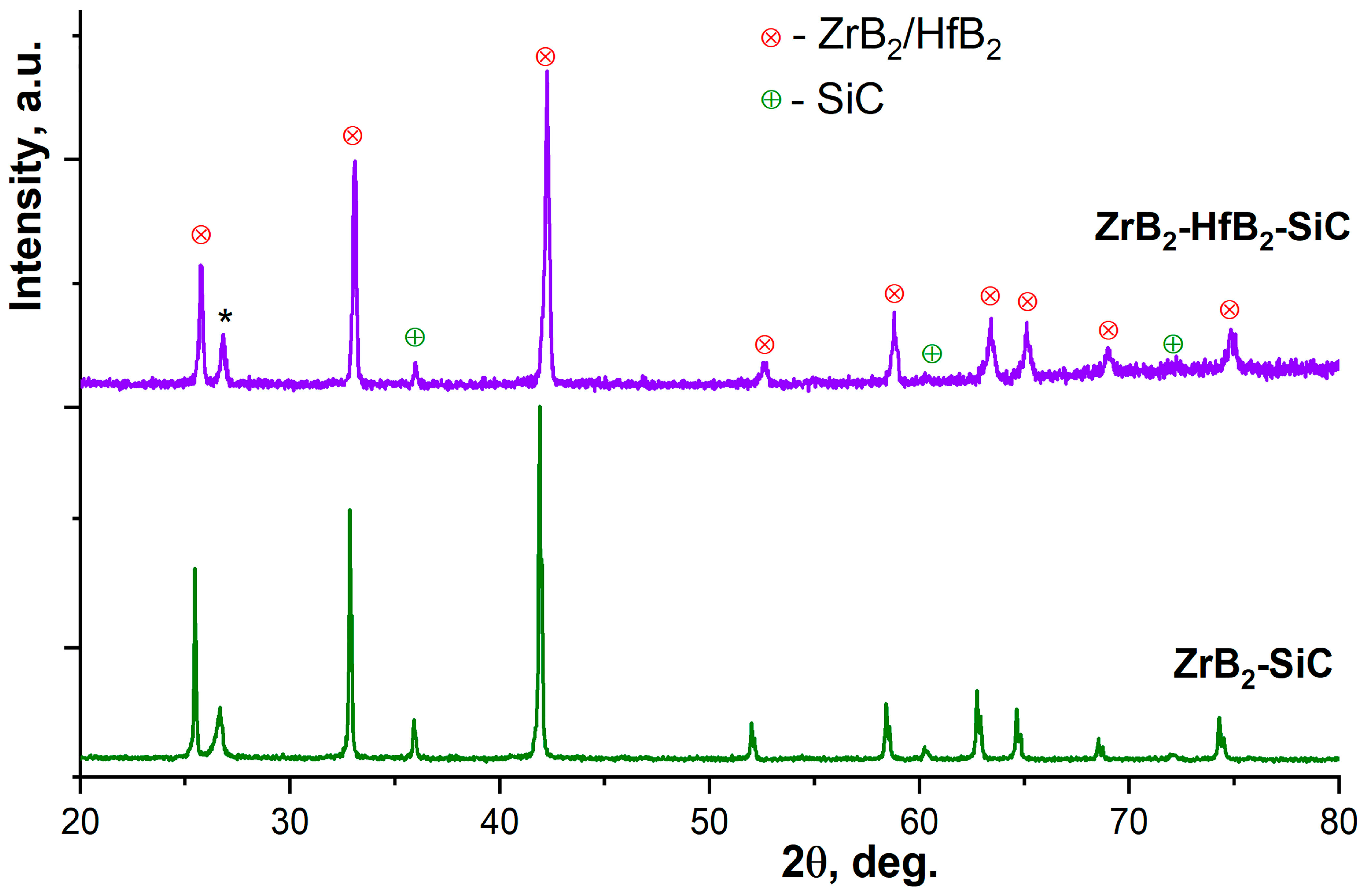
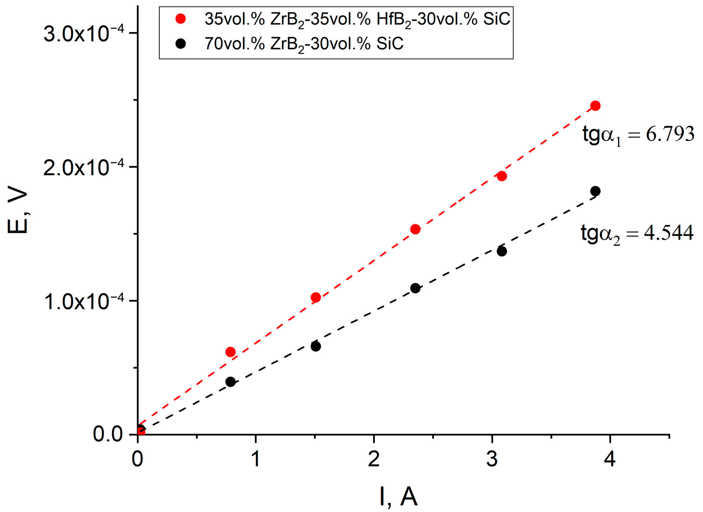
3.1. An Investigation of ZrB2-SiC and ZrB2-HfB2-SiC Ceramic Samples Obtained Using the SPS Method of Reaction

The determination of the density of the obtained samples demonstrated that the nature of the metal diboride had a negligible impact on the consolidation result. Therefore, the relative density in comparison with the additive densities for the systems ZrB2-SiC and ZrB2-HfB2-SiC for sample ZS was 93.2 ± 3.6%, and for sample ZHS, it was 92.3 ± 4.4%, which is within the error range (porosity is ~7–8%). The following values were employed in the calculations: the values for SiC [75], ZrB2 [76], and HfB2 [77] were 3.2, 6.1, and 11.2 g/cm3, respectively.
The X-ray phase analysis (Figure 1) indicates that the selected consolidation conditions (two-stage heating in the SPS mode) are sufficient for the complete synthesis of cubic silicon carbide (ICSD card #24217) [78] based on the SiO2-C system obtained using the sol-gel method and distributed on the surface of diboride particles. In this case, the primary phase of the ZS sample is hexagonal ZrB2 (ICSD card #615754) [79], whereas the ZHS sample exhibits a hexagonal phase whose reflex position is intermediate between ZrB2 [79] and HfB2 (ICSD card #614422) [80], which may indicate the formation of a solid solution based on these two phases. However, the observed shift is not proportional to the initial equal amounts of zirconium and hafnium diborides.
The microstructure analysis of the materials (Figure 2) corroborates the findings of the density measurement, demonstrating the absence of significant porosity in the microphotographs. The chipping of the materials reveals the presence of areas of formed silicon carbide between the ZrB2/HfB2 grains, which exhibit splinter-like shapes. The average SiC grain size was found to be 1.8 ± 0.9 μm and 1.7 ± 0.8 μm for the ZS and ZHS samples, respectively, while the grain size of the metal diborides was 3.1 ± 1.0 μm (ZS) and 2.3 ± 0.7 μm (ZHS). Consequently, the presence of diboride grains does not permit the accurate determination of the potential for the formation of a ZrB2-HfB2 solid solution, as there are no discernible indications of the existence of discrete ZrB2 and HfB2 grains. The mapping of the distribution of Si, Zr, and Hf elements on the surface of the ZS and ZHS samples indicates that the phase of synthesized silicon carbide is uniformly distributed between the metal diboride grains (Figure 3). Conversely, in the case of ZHS ceramics, although the simultaneous presence of Zr and Hf elements in the grains in which silicon is absent is observed, the formation of nuclei based on ZrB2 is nevertheless evident within these regions. In light of the aforementioned XRD data, it can be posited that there is a partial mutual dissolution of the ZrB2 and HfB2 phases, resulting in the formation of two solid solutions with closely matching lattice parameters. It seems likely that the chosen holding time at 1800 °C was insufficient for the full mutual diffusion of the refractory boride components, which is necessary for the formation of the ZrB2-HfB2 solid solution with the given composition.
The four-contact method was employed to conduct the requisite measurements, the results of which are presented in Figure 4. These results demonstrate the linear dependence of the voltage measured on the samples under study on the value of the current flowing through them. The observed character of the dependence indicates that the contact resistance does not contribute to the measured resistance of the samples, which, in this case, is equal to the tangent of the slope of the obtained curve. By employing the calculated values of tgα1 and tgα2, along with the known geometrical dimensions of the measured samples, it is possible to estimate their respective electrical conductivities, which were found to be 2.79 × 10⁶ (ZS) and 1.87 × 10⁶ Cm/m (ZHS). The obtained values are in accordance with the literature data related to materials of a similar composition [81,82]. Conversely, the observed decline in the ZHS sample’s conductivity upon the introduction of 35 mol% hafnium boride is likely attributable to the latter’s enhanced resistance. In particular, it was demonstrated in [83] that composites in the HfB2–SiC system exhibit higher resistivity values than ceramic samples based on zirconium diboride at the same silicon carbide content. It should be noted that discrepancies in the reported electrical resistances of these materials may be attributed to various factors, including the specificities of the sintering process in ceramic systems, variations in composite density and grain size, and the potential presence of impurities.
The results of the atomic force microscopy study of the microstructure of the ZS and ZHS samples (Figure S1) demonstrate that the grains of the materials are composed of submicron formations, with sizes of approximately 100–500 nm. Additionally, the surface of the grains exhibits a high degree of smoothness, with height differences reaching only a few tens of nm. The KPFM studies enabled the determination of the electron work function from the surface of the materials, which was 4.07 eV (ZS) and 4.45 eV (ZHS). These values align with the literature data on the work function for individual components of the materials [84,85]. It can be observed that the introduction of HfB2 into the system results in an increase in the value of work function, which may be indicative of a lower electrical conductivity of the material ZHS in comparison to ZS. This finding aligns with the results of measurements conducted using the four-contact method (Figure 4). The I-V curves of the probe–sample contact on the material surface (Figure 5), which were also obtained using AFM, indicate the high conductivity of ZHS and ZS. A very steep and direct current–voltage dependence is observed up to a current value of 20 nA (or –20 nA), after which a non-linear dependence is observed due to the features of the device design.

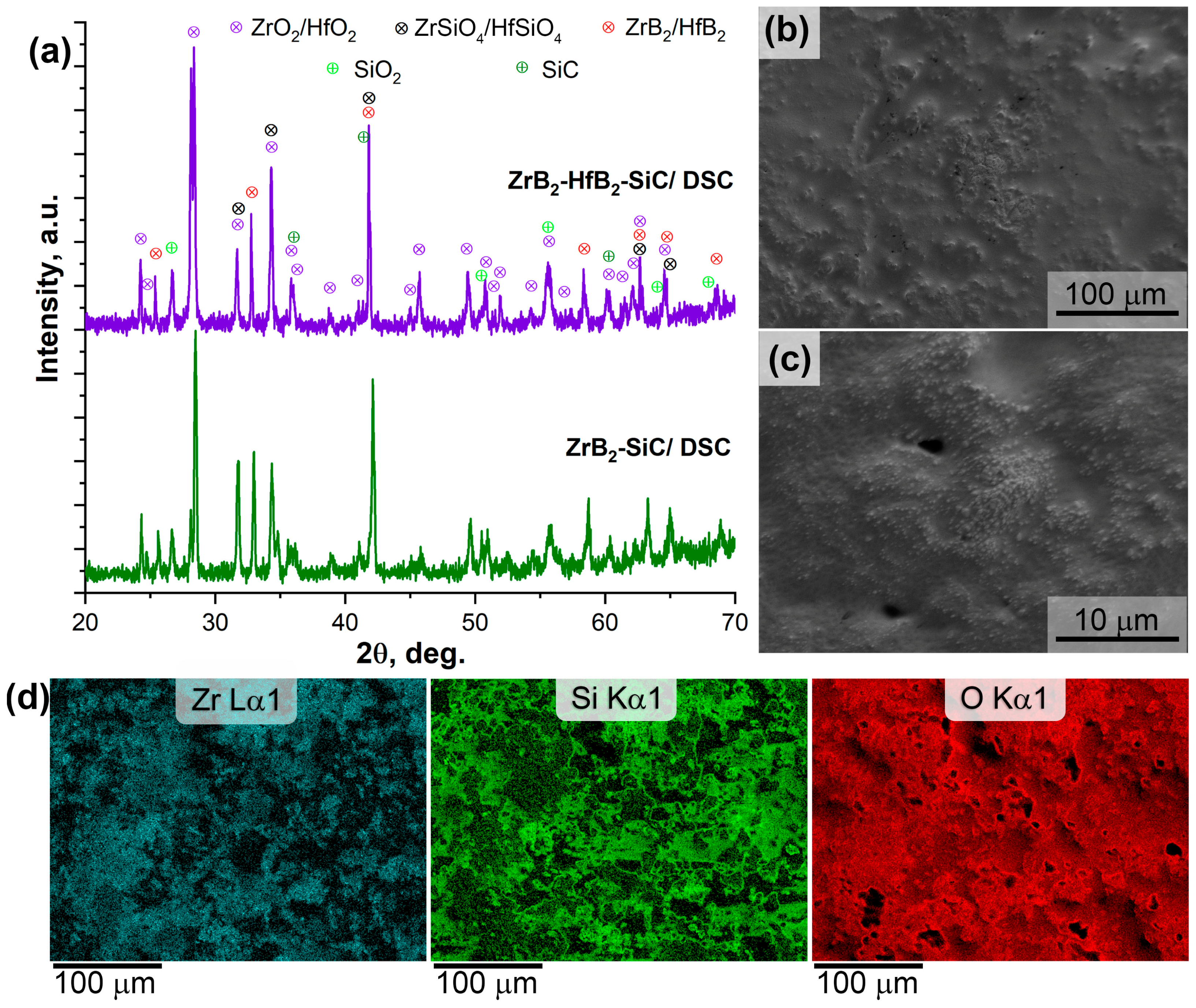
3.2. Heating Behavior of ZrB2-SiC and ZrB2-HfB2-SiC Materials during Heating in an Air Current (DSC/TG)

The combined DSC/TGA data (Figure 6) in an air current in the range of 20–1200 °C revealed that the thermal behavior of the fabricated ceramic materials is comparable. The mass gain for both samples does not exceed 0.5%. The slightly lower mass gain (Δm = 0.29%) for the ZHS sample compared to ZH (0.43%) can also be attributed to the presence of HfB2, a heavier element, in its composition, in addition to ZrB2.
The position of the maximum of the endothermic thermal effects is practically identical for the ZrB2-SiC and ZrB2-HfB2-SiC compositions. The mass gain resulting from oxidation commences within the temperature range of 720–725 °C, with a discernible acceleration in the rate of gain occurring at temperatures of 898 °C (for the ZS sample) and 905 °C (for the ZHS sample). This is consistent with the observed difference in oxidation resistance between HfB2 and ZrB2 [2], as the formation of silicon carbide at rapid heating and low temperatures is unlikely to significantly contribute to oxidation. It can be reasonably assumed that an increase in temperature above 900–1000 °C will result in the oxidation of SiC.
The phase composition of the oxidized surface of the samples was analyzed, and a typical pattern of formation of crystalline oxidation products was observed (Figure 7a). These included ZrO2 (ICSD card #94887) [84], HfO2 (ICSD card #173158) [85], ZrSiO4 (ICSD card #98570) [86], HfSiO4 (ICSD card #31177) [87], weakly ordered quartz configuration (ICSD card #168355) [88]) with partially preserved initial phases ZrB2/HfB2 [80,89] (not exceeding 10–15 wt.%), and SiC [90] (not exceeding 8 wt.%). Concurrently, the mass ratio of ZrO2 and ZrSiO4 for the ZS sample was nearly 1:1 (with a slight predominance of zircon), whereas, for the ZHS sample, the concentration of zirconium and hafnium oxides markedly exceeded that of the ZrSiO4 + HfSiO4 aggregate (nearly fivefold). This phenomenon may be related to the differing solubilities of zirconium and hafnium oxides in the X-ray amorphous borosilicate glass present in the localized area of the sample surface. As illustrated in Figure 7b,c, the DSC mode of the ZS sample heated to 1200 °C in an air current reveals that the borosilicate glass is predominant on the surface, through which ZrO2/ZrSiO4 particles with a diameter of 150–500 nm are visible. Therefore, within the selected oxidation regime, the materials ZrB2-SiC and ZrB2-HfB2-SiC, which are produced through reactive spark plasma sintering, demonstrate comparable behavior.

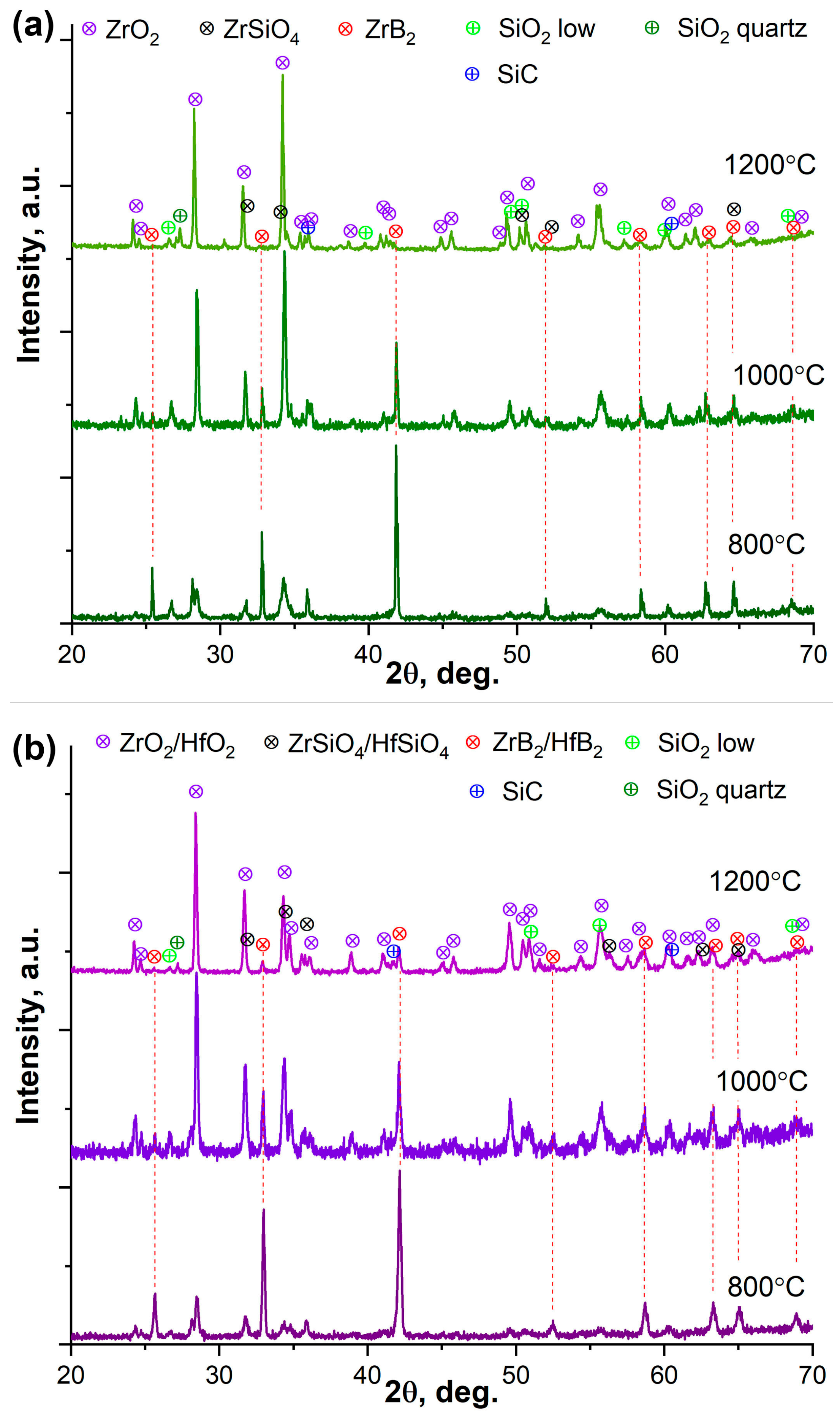
3.3. Oxidation Resistance of ZrB2-SiC and ZrB2-HfB2-SiC Materials Under Static Heating

In order to elucidate the peculiarities of the oxidation of the fabricated materials at temperatures of 800 °C (in the vicinity of which the maximum thermal effects were observed in the DSC experiment), 1000 °C (at which the beginning of significant oxidation of the SiC phase is expected), and 1200 °C (the maximum DSC temperature), prolonged exposures were carried out in a muffle furnace in an air atmosphere (for 60 min, heating rate 300°/h, cooling with the furnace).
X-ray diffraction of the oxidized surface of the samples (Figure 8) demonstrated that during heat treatment in the air at a minimum temperature of 800 °C for both samples, not only zirconium and hafnium diborides but also silicon carbide oxidation occurred. In addition to the ZrO2(HfO2) and ZrSiO4(HfSiO4) phases, the presence of weakly structured quartz reflexes on X-ray diffraction patterns was observed [88]. Furthermore, an analysis of the crystalline phases indicates that the ZS sample exhibits a slightly higher degree of degradation than the ZHS sample. The initial ZrB2 content in the ZS sample is approximately 35 wt.%, while in the ZHS sample, it is approximately 50 wt.%. The surface of the ZS and ZHS samples is characterized by the prevalence of monoclinic zirconium and hafnium dioxides [84,85] (25–28 wt.%), with a zircon content on the surface of the ZS sample that does not exceed 4 wt.%. The combined content of hafnium and zircon for the ZHS sample is approximately 10 wt.%.
An increase in the heat treatment temperature to 1000 and 1200 °C results in a notable reduction in the surface content of ZrB2 (~8 and 1–2 wt.%, respectively) for the ZS sample and ZrB2 + HfB2 (~14 and 5 wt.%, respectively) for the ZHS sample. This also suggests that the sample containing HfB2 exhibits slightly enhanced oxidation resistance at moderate temperatures. The principal phases present on the surface at these temperatures are monoclinic zirconium and hafnium dioxides, representing a weight percentage of approximately 64–68%. The concentration of zircon consistently increases to approximately 7 wt.% for the ZS sample, while the ZrSiO4 + HfSiO4 content remains at 10 ± 1 wt.%. Furthermore, upon calcination of both samples at 1200 °C, an additional quartz phase with an elevated pressure structure was observed (ICSD card #41471) [91].
The microstructure of the oxidized surface and the distribution of Zr(Hf), Si, and O elements of the ZS (Figure 9) and ZHS (Figure 10) samples were analyzed, as expected, and it was demonstrated that in addition to crystalline reaction products, amorphous products in the form of borosilicate glass are also formed. Concomitantly, the quantity of this amorphous phase is markedly contingent upon the oxidation temperature. Therefore, following the soaking of both samples at 800 °C, the presence of an amorphous silicate phase on the surface was evident. This phase allowed for the observation of inclusions of more refractory products (mainly ZrO2 and HfO2) through it. The distribution of elements indicates a relatively clear localization of silicon, which is probably present in both the SiC and SiO2 forms, as evidenced by a comparison of the Si and O distributions. At a higher temperature of 1000 °C, the situation differs slightly for the samples of the original composition ZrB2-SiC (ZS) and ZrB2-HfB2-SiC (ZHS). In contrast, the ZS sample exhibits a markedly more uniform distribution of silicon across the surface, with the preservation of select regions exhibiting a higher concentration of approximately 3 × 10 μm. This distribution aligns nearly perfectly with the oxygen distribution (Figure 9, temperature 1000 °C). In comparison, the ZHS sample displays a more heterogeneous distribution of silicon, with localized concentrations observed in small areas of approximately 1.5–3 μm. These concentrations correspond to the grain size of the initial SiC (Figure 10, temperature 1000 °C). The distribution of silicon in small areas of approximately 1.5–3 μm (corresponding to the grain size of the initial SiC, Figure 10, temperature 1000 °C) is preserved, while the distribution of Si over a larger surface (accompanied by the oxygen distribution) is also evident. At the highest temperature of oxidation, which is 1200 °C, both samples exhibited the preferential formation of molten glass from oxidation products, accompanied by a uniform distribution of Si and O atoms. It is noteworthy that the ZHS sample exhibits a non-uniform mutual distribution of Zr and Hf atoms, which is characteristic of the initial ceramics. This indicates the presence of a “nucleus” of ZrB2 oxidation products, around which HfB2 oxidation products are distributed.
An EDX analysis revealed that following calcination at 800 °C, both materials exhibited regions with a prevalence of silicon, zirconium, and hafnium. This observation reflects the localization of initial SiC and ZrB2/(ZrB2 + HfB2) grains and their oxidation products. The application of elevated temperatures results in the formation of a uniform surface and a notable enhancement in the n(Si)/n(Zr) and n(Si)/n(Zr + Hf) ratios, reaching values of 1:2 (1000 °C) and 6:20 (1200 °C), respectively. This suggests that the surface contains an increasing amount of borosilicate glass as the temperature of the heat treatment increases. Furthermore, at 1200 °C, the oxidation resistance of the obtained materials exhibits a discernible difference. Therefore, for sample ZS, the ratio of n(Si)/n(Zr) varies considerably, spanning a wide range of 7:19, whereas for the hafnium-containing material ZHS, the ratio of n(Si)/n(Zr + Hf) for different sites is more constrained, falling within a narrower range of 6.4:6.7. This suggests that the quantity of borosilicate melt extruded by CO and SiO, formed during oxidation in deeper layers to the surface, is greater for the ZS sample than for the ZHS material. This may indicate a more profound degree of degradation of the ZrB2-SiC material.
As illustrated in Figure 5, the attempt to record the AFM probe–sample contact I-V curve on the surface of the oxidized samples reveals the absence of electrical contact following heat treatment in air at 1200 °C. This observation suggests the formation of a dielectric material film. The KPFM of the oxidized ZS and ZHS samples also demonstrates that a considerable static charge accumulates on the surface of the oxidized samples, thereby preventing the measurement of the work function. This behavior is characteristic of a dielectric material, such as SiO2. Nevertheless, while contact potential values up to 12 V are observed on the surface of the calcined ZS sample, in the case of ZHS, this parameter has a scatter of only 0.6 V to 1.8 V. This suggests the formation of a smaller amount of dielectric on the surface of the material, which may indicate greater resistance to oxidation compared to ZS.

4. Conclusions

A method of manufacturing ultra-high-temperature ceramics of composition ZrB2-30 vol.%SiC and (ZrB2-HfB2)-30 vol.% SiC has been developed. This method employs the two-stage reaction spark plasma sintering of composite powders ZrB2(HfB2)-(SiO2-C) at temperatures of 1400 and 1800 °C, with a holding time at the highest temperature for 30 min. It was determined that this method, irrespective of the composition, enables the production of ceramic materials with a relative density of 92–93%. In the case of materials containing both ZrB2 and HfB2, no complete dissolution of the boride components into one another occurs. Instead, two solid solutions are formed, comprising a ZrB2 core and a HfB2 shell. It is likely that the duration of holding the samples at the SPS temperature of 1800 °C was insufficient for the formation of a true ZrB2-HfB2 solid solution. The four-contact method was employed to ascertain the electrical conductivity of the obtained materials, yielding values of 2.79 × 10⁶ (ZS) and 1.87 × 10⁶ Cm/m (ZHS), respectively. The electron work function, as determined from the Kelvin probe force microscopy data, was 4.45 eV and 4.07 eV for the (ZrB2-HfB2)-30 vol.% SiC and ZrB2-30 vol.% SiC samples, respectively. The I-V curves of the probe–sample contacts on the material surface corroborate the data on the electrical conductivity of the obtained materials.
Experiments were conducted to examine the oxidation resistance of the fabricated ceramics. The samples were subjected to two distinct oxidation treatments: heating to 1200 °C in the air (in DSC mode) and holding in a muffle furnace at temperatures of 800, 1000, and 1200 °C for 60 min. The results demonstrated that the resistance of UHTC to these oxidation processes was comparable across all compositions. Nevertheless, the oxidation resistance of the HfB2-containing ceramics was slightly higher. This is corroborated by the elevated ZrB2 and HfB2 concentrations on the surface following oxidation at temperatures of 800–1200 °C for the ZHS sample (as evidenced by XRD data) and by the disparity in the distribution of Si and O elements on the surface of the samples oxidized at 1000 °C.
The I-V curves of the probe–sample contacts on the oxidized material surface provide qualitative evidence that oxidation of the materials has occurred. Additionally, Kelvin probe force microscopy provides indirect confirmation that the ceramics containing HfB2 exhibit enhanced resistance to oxidation.

Supplementary Materials

The following supporting information can be downloaded at https://www.mdpi.com/article/10.3390/ceramics7040101/s1: Figure S1: Microstructure (AFM) of ZS and ZHS samples before and after heating at 1200 °C.

Author Contributions

Conceptualization, E.P.S., N.P.S., E.K.P. and N.T.K.; methodology, E.P.S., E.K.P. and N.T.K.; validation, O.O.S., T.L.S., O.O.S. and N.P.S.; investigation, I.A.N., T.L.S., P.Y.G., M.A.T., A.S.M., O.O.S., A.A.B. and N.P.S.; resources, E.K.P., M.A.T. and N.T.K.; writing—original draft preparation, E.P.S., I.A.N., P.Y.G., M.A.T., A.S.M. and A.A.B.; writing—review and editing, I.A.N., T.L.S., P.Y.G., A.S.M. and A.A.B.; supervision, N.T.K.; project administration, E.P.S.; funding acquisition, E.P.S. All authors have read and agreed to the published version of the manuscript.

Funding

This study is performed within the ARIADNA Collaboration operating under the NICA facility as a part of the State Assignment of the IGIC RAS “Solving topical problems with NICA charged particle beams (ref. # 1024050300012-6-1.4.2)”.

Institutional Review Board Statement

Not applicable.

Informed Consent Statement

Not applicable.

Data Availability Statement

The original contributions presented in this study are included in the article/Supplementary Material, and further inquiries can be directed to the corresponding author.

Conflicts of Interest

The authors declare no conflicts of interest.

References

  1. Simonenko, E.P.; Sevast’yanov, D.V.; Simonenko, N.P.; Sevast’yanov, V.G.; Kuznetsov, N.T. Promising ultra-high-temperature ceramic materials for aerospace applications. Russ. J. Inorg. Chem. 2013, 58, 1669–1693. [Google Scholar] [CrossRef]
  2. Opeka, M.M.; Talmy, I.G.; Zaykoski, J.A. Oxidation-based materials selection for 2000 °C + hypersonic aerosurfaces: Theoretical considerations and historical experience. J. Mater. Sci. 2004, 39, 5887–5904. [Google Scholar] [CrossRef]
  3. Wuchina, E.; Opila, E.; Opeka, M.; Fahrenholtz, B.; Talmy, I. UHTCs: Ultra-high temperature ceramic materials for extreme environment applications. Electrochem. Soc. Interface 2007, 16, 30. [Google Scholar] [CrossRef]
  4. Ni, D.; Cheng, Y.; Zhang, J.; Liu, J.-X.; Zou, J.; Chen, B.; Wu, H.; Li, H.; Dong, S.; Han, J.; et al. Advances in ultra-high temperature ceramics, composites, and coatings. J. Adv. Ceram. 2022, 11, 1–56. [Google Scholar] [CrossRef]
  5. Golla, B.R.; Mukhopadhyay, A.; Basu, B.; Thimmappa, S.K. Review on ultra-high temperature boride ceramics. Prog. Mater. Sci. 2020, 111, 100651. [Google Scholar] [CrossRef]
  6. Mor, M.; Vinci, A.; Sciti, D. Processing and oxidation resistance at 1650 °C of ZrB2-based UHTCMCs with short fibre gradients. J. Eur. Ceram. Soc. 2024, 44, 4536–4548. [Google Scholar] [CrossRef]
  7. Zhang, C.; Hu, P.; Xun, L.; Zhou, Y.; Han, J.; Zhang, X. A universal strategy towards the fabrication of ultra-high temperature ceramic matrix composites with outstanding mechanical properties and ablation resistance. Compos. Part B Eng. 2024, 280, 111485. [Google Scholar] [CrossRef]
  8. Silvestroni, L.; Pavan, D.; Melandri, C.; Sciti, D.; Gilli, N.; Ortiz-Membrado, L.; Jiménez-Piqué, E.; Grande, A.M. Functionally graded ultra-high temperature ceramics: From thermo-elastic numerical analysis to damage tolerant composites. Mater. Des. 2022, 224, 111379. [Google Scholar] [CrossRef]
  9. Zhang, M.; Hu, D.; Fu, Q. Ablation resistant behavior of silicide modified HfB2-SiC coating on graphite by spark plasma sintering: Role of MeSi2 addition. J. Eur. Ceram. Soc. 2024, 44, 6286–6297. [Google Scholar] [CrossRef]
  10. Han, J.; Hu, P.; Zhang, X.; Meng, S.; Han, W. Oxidation-resistant ZrB2–SiC composites at 2200 °C. Compos. Sci. Technol. 2008, 68, 799–806. [Google Scholar] [CrossRef]
  11. Tang, S.; Hu, C. Design, Preparation and Properties of Carbon Fiber Reinforced Ultra-High Temperature Ceramic Composites for Aerospace Applications: A Review. J. Mater. Sci. Technol. 2017, 33, 117–130. [Google Scholar] [CrossRef]
  12. Squire, T.H.; Marschall, J. Material property requirements for analysis and design of UHTC components in hypersonic applications. J. Eur. Ceram. Soc. 2010, 30, 2239–2251. [Google Scholar] [CrossRef]
  13. Nisar, A.; Hassan, R.; Agarwal, A.; Balani, K. Ultra-high temperature ceramics: Aspiration to overcome challenges in thermal protection systems. Ceram. Int. 2022, 48, 8852–8881. [Google Scholar] [CrossRef]
  14. Mungiguerra, S.; Cecere, A.; Savino, R.; Saraga, F.; Monteverde, F.; Sciti, D. Improved aero-thermal resistance capabilities of ZrB2-based ceramics in hypersonic environment for increasing SiC content. Corros. Sci. 2021, 178, 109067. [Google Scholar] [CrossRef]
  15. Mungiguerra, S.; Di Martino, G.D.; Cecere, A.; Savino, R.; Zoli, L.; Silvestroni, L.; Sciti, D. Ultra-high-temperature testing of sintered ZrB2-based ceramic composites in atmospheric re-entry environment. Int. J. Heat Mass Transf. 2020, 156, 119910. [Google Scholar] [CrossRef]
  16. Rita, C.C.P.; Miranda, F.d.S.; Caliari, F.R.; Rocha, R.M.; Essiptchouk, A.; Charakhovski, L.; Filho, G.P. Hypersonic Plasma Setup for Oxidation Testing of Ultrahigh Temperature Ceramic Composites. J. Heat Transf. 2020, 142, 082103. [Google Scholar] [CrossRef]
  17. Mor, M.; Meiser, M.; Langhof, N.; Vinci, A.; Zoli, L.; Alber-Laukant, B.; Tremmel, S.; Schafföner, S.; Sciti, D. Dry tribological behavior of 0/90° continuous carbon fiber reinforced ZrB2 based UHTC-material. J. Eur. Ceram. Soc. 2024, 44, 116664. [Google Scholar] [CrossRef]
  18. López-Arenal, J.; Moshtaghioun, B.M.; Gómez-García, D.; Ortiz, A.L. Processing of ZrB2 tribo-ceramics by reactive spark plasma sintering of ZrH2+2B subjected to high-energy pre-ball-milling. J. Eur. Ceram. Soc. 2023, 43, 5195–5206. [Google Scholar] [CrossRef]
  19. Hassan, R.; Patro, D.; Josyula, S.K.; Omar, S.; Balani, K. Incessant tribo-layer formation supresses high temperature wear damage in SiC reinforced equi-volume ZrB2-HfB2 composite. Surf. Coat. Technol. 2023, 465, 129586. [Google Scholar] [CrossRef]
  20. Sciti, D.; Guicciardi, S.; Zoli, L.; Failla, S.; Melandri, C. Dry sliding wear behaviour of ZrB2-based ceramics: Self-mated and cross coupling with alumina. J. Eur. Ceram. Soc. 2022, 42, 6335–6346. [Google Scholar] [CrossRef]
  21. Gupta, Y.; Kumar, B.V.M. ZrB2–SiC composites for sliding wear contacts: Influence of SiC content and counterbody. Ceram. Int. 2022, 48, 14560–14567. [Google Scholar] [CrossRef]
  22. Silvestroni, L.; Mungiguerra, S.; Sciti, D.; Di Martino, G.D.; Savino, R. Effect of hypersonic flow chemical composition on the oxidation behavior of a super-strong UHTC. Corros. Sci. 2019, 159, 108125. [Google Scholar] [CrossRef]
  23. Ma, H.-B.; Zou, J.; Zhu, J.-T.; Liu, L.-F.; Zhang, G.-J. Segregation of tungsten atoms at ZrB2 grain boundaries in strong ZrB2-SiC-WC ceramics. Scr. Mater. 2018, 157, 76–80. [Google Scholar] [CrossRef]
  24. Ma, H.-B.; Zou, J.; Zhu, J.-T.; Lu, P.; Xu, F.-F.; Zhang, G.-J. Thermal and electrical transport in ZrB2-SiC-WC ceramics up to 1800 °C. Acta Mater. 2017, 129, 159–169. [Google Scholar] [CrossRef]
  25. Ifti, H.S.; Hermann, T.; McGilvray, M.; Larrimbe, L.; Hedgecock, R.; Vandeperre, L. Flow Characterization of Porous Ultra-High-Temperature Ceramics for Transpiration Cooling. AIAA J. 2022, 60, 3286–3297. [Google Scholar] [CrossRef]
  26. Liu, D.; Jin, X.; Li, N.; Li, J.; Zhang, S.; Yi, T.; Li, X.; Li, X.; Zhang, B.; Dong, L.; et al. In-situ synthesis of hierarchically high porosity ZrB2 ceramics from carbon aerogel template with excellent performance in thermal insulation and light absorption. J. Eur. Ceram. Soc. 2024, 44, 738–747. [Google Scholar] [CrossRef]
  27. Zhao, K.; Ye, F.; Cheng, L.; Yang, J.; Chen, X. An overview of ultra-high temperature ceramic for thermal insulation: Structure and composition design with thermal conductivity regulation. J. Eur. Ceram. Soc. 2023, 43, 7241–7262. [Google Scholar] [CrossRef]
  28. Zhang, X.; He, J.; Han, L.; Huang, Z.; Xu, K.; Cai, W.; Wu, S.; Jia, Q.; Zhang, H.; Zhang, S. Foam gel-casting preparation of SiC bonded ZrB2 porous ceramics for high-performance thermal insulation. J. Eur. Ceram. Soc. 2023, 43, 37–46. [Google Scholar] [CrossRef]
  29. Zoli, L.; Failla, S.; Sani, E.; Sciti, D. Novel ceramic fibre-Zirconium diboride composites for solar receivers in concentrating solar power systems. Compos. Part B Eng. 2022, 242, 110081. [Google Scholar] [CrossRef]
  30. Barbarossa, S.; Orrù, R.; Cao, G.; Balbo, A.; Zanotto, F.; Sani, E. Optical properties of bulk high-entropy diborides for solar energy applications. J. Alloys Compd. 2023, 935, 167965. [Google Scholar] [CrossRef]
  31. Qiu, X.-L.; He, C.-Y.; Zhao, P.; Liu, B.-H.; Guo, H.-X.; Liu, G.; Gao, X.-H. Reinforcement optical performance and thermal tolerance in a TiB2-HfB2-based double-layer spectral selective absorber via a pre-annealing strategy. Mater. Today Phys. 2022, 24, 100690. [Google Scholar] [CrossRef]
  32. Chaplygin, A.; Simonenko, E.; Simonenko, N.; Kotov, M.; Yakimov, M.; Lukomskii, I.; Galkin, S.; Kolesnikov, A.; Vasil’evskii, S.; Shemyakin, A.; et al. Heat transfer and behavior of ultra high temperature ceramic materials under exposure to supersonic carbon dioxide plasma with additional laser irradiation. Int. J. Therm. Sci. 2024, 201, 109005. [Google Scholar] [CrossRef]
  33. Marschall, J.; Pejaković, D.A.; Fahrenholtz, W.G.; Hilmas, G.E.; Panerai, F.; Chazot, O. Temperature Jump Phenomenon During Plasmatron Testing of ZrB2-SiC Ultrahigh-Temperature Ceramics. J. Thermophys. Heat Transf. 2012, 26, 559–572. [Google Scholar] [CrossRef]
  34. Sevastyanov, V.G.; Simonenko, E.P.; Gordeev, A.N.; Simonenko, N.P.; Kolesnikov, A.F.; Papynov, E.K.; Shichalin, O.O.; Avramenko, V.A.; Kuznetsov, N.T. HfB2-SiC (45 vol %) ceramic material: Manufacture and behavior under long-term exposure to dissociated air jet flow. Russ. J. Inorg. Chem. 2014, 59, 1298–1311. [Google Scholar] [CrossRef]
  35. Simonenko, E.P.; Kolesnikov, A.F.; Chaplygin, A.V.; Kotov, M.A.; Yakimov, M.Y.; Lukomskii, I.V.; Galkin, S.S.; Shemyakin, A.N.; Solovyov, N.G.; Lysenkov, A.S.; et al. Oxidation of Ceramic Materials Based on HfB2-SiC under the Influence of Supersonic CO2 Jets and Additional Laser Heating. Int. J. Mol. Sci. 2023, 24, 13634. [Google Scholar] [CrossRef]
  36. Chaplygin, A.V.; Simonenko, E.P.; Kotov, M.A.; Sakharov, V.I.; Lukomskii, I.V.; Galkin, S.S.; Kolesnikov, A.F.; Lysenkov, A.S.; Nagornov, I.A.; Mokrushin, A.S.; et al. Short-Term Oxidation of HfB2-SiC Based UHTC in Supersonic Flow of Carbon Dioxide Plasma. Plasma 2024, 7, 300–315. [Google Scholar] [CrossRef]
  37. Simonenko, E.P.; Simonenko, N.P.; Kolesnikov, A.F.; Chaplygin, A.V.; Papynov, E.K.; Shichalin, O.O.; Belov, A.A.; Nagornov, I.A.; Mokrushin, A.S.; Kuznetsov, N.T. Effect of Supersonic Nitrogen Flow on Ceramic Material Ta4HfC5–SiC. Russ. J. Inorg. Chem. 2023, 68, 479–486. [Google Scholar] [CrossRef]
  38. Monteverde, F.; Savino, R. Stability of ultra-high-temperature ZrB2–SiC ceramics under simulated atmospheric re-entry conditions. J. Eur. Ceram. Soc. 2007, 27, 4797–4805. [Google Scholar] [CrossRef]
  39. Savino, R.; Fumo, M.D.S.; Silvestroni, L.; Sciti, D. Arc-jet testing on HfB2 and HfC-based ultra-high temperature ceramic materials. J. Eur. Ceram. Soc. 2008, 28, 1899–1907. [Google Scholar] [CrossRef]
  40. Kolesnikov, A.F.; Kuznetsov, N.T.; Muravyeva, T.I.; Nagornov, I.A.; Sakharov, V.I.; Sevastyanov, V.G.; Simonenko, E.P.; Simonenko, N.P.; Chaplygin, A.V.; Shcherbakova, O.O. Investigation of Heat Transfer to HfB2-SiC-Based Ceramics in Underexpanded Dissociated-Nitrogen Flows and Analysis of the Surface. Fluid Dyn. 2022, 57, 513–523. [Google Scholar] [CrossRef]
  41. Simonenko, E.P.; Simonenko, N.P.; Kolesnikov, A.F.; Chaplygin, A.V.; Lysenkov, A.S.; Nagornov, I.A.; Mokrushin, A.S.; Kuznetsov, N.T. Investigation of the Effect of Supersonic Flow of Dissociated Nitrogen on ZrB2–HfB2–SiC Ceramics Doped with 10 vol.% Carbon Nanotubes. Materials 2022, 15, 8507. [Google Scholar] [CrossRef] [PubMed]
  42. Simonenko, E.P.; Kolesnikov, A.F.; Chaplygin, A.V.; Lysenkov, A.S.; Nagornov, I.A.; Lukomskii, I.V.; Galkin, S.S.; Mokrushin, A.S.; Simonenko, N.P.; Kuznetsov, N.T. Transformation of the Surface of HfB2–SiC–C(graphene) Ultrahigh-Temperature Ceramics in a High-Velocity Flow of Dissociated Nitrogen. Russ. J. Inorg. Chem. 2024, 69, 517. [Google Scholar] [CrossRef]
  43. Yang, M.; Tian, X.; Gao, C.; Guo, D.; Liu, J.; Xie, L.; Zhao, S.; Liu, H.; Sun, X. A 4.25-Gbps serializer ASIC in 180 nm for the monolithic active pixel sensor of the NICA-MPD Inner Tracker System. Nucl. Instrum. Methods Phys. Res. Sect. A Accel. Spectrom. Detect. Assoc. Equip. 2024, 1064, 169357. [Google Scholar] [CrossRef]
  44. Baryshnikov, V.; Babkin, V.; Buzin, S.; Burdyko, A.; Buryakov, M.; Golovatyuk, V.; Dmitriev, A.; Dulov, P.; Rumyantsev, M.; Romakhov, S.; et al. Status of the Time-of-Flight System of the MPD Experiment at the NICA Collider. Phys. At. Nucl. 2023, 86, 788–795. [Google Scholar] [CrossRef]
  45. Avdeev, S.P.; Busin, S.G.; Buryakov, M.G.; Golovatyuk, V.M.; Malakhov, A.I.; Milnov, G.D.; Kurepin, A.B.; Litvinenko, A.G.; Litvinenko, E.I. Detector for Setting Up Beam Convergence and Determining Luminosity at the Interaction Point on the MPD NICA. Phys. At. Nucl. 2023, 86, 680–691. [Google Scholar] [CrossRef]
  46. Guo, S.-Q. Densification of ZrB2-based composites and their mechanical and physical properties: A review. J. Eur. Ceram. Soc. 2009, 29, 995–1011. [Google Scholar] [CrossRef]
  47. Chamberlain, A.L.; Fahrenholtz, W.G.; Hilmas, G.E. Pressureless Sintering of Zirconium Diboride. J. Am. Ceram. Soc. 2006, 89, 450–456. [Google Scholar] [CrossRef]
  48. Zhu, S.; Fahrenholtz, W.G.; Hilmas, G.E. Influence of silicon carbide particle size on the microstructure and mechanical properties of zirconium diboride–silicon carbide ceramics. J. Eur. Ceram. Soc. 2007, 27, 2077–2083. [Google Scholar] [CrossRef]
  49. Rezaie, A.; Fahrenholtz, W.G.; Hilmas, G.E. Effect of hot pressing time and temperature on the microstructure and mechanical properties of ZrB2–SiC. J. Mater. Sci. 2007, 42, 2735–2744. [Google Scholar] [CrossRef]
  50. Mao, C.; Ren, X.; Ji, X.; Xu, L.; Wang, X.; Zhu, N.; Zhang, P.; Feng, P. High-temperature oxidation resistance of spent MoSi2 modified ZrB2–SiC–MoSi2 coatings prepared by spark plasma sintering. Ceram. Int. 2023, 49, 32913–32922. [Google Scholar] [CrossRef]
  51. Pellegrini, C.; Balat-Pichelin, M.; Rapaud, O.; Bêche, E.; Thébault, Y. Oxidation resistance up to 2600 K under air plasma of (Zr/Hf)B2 composites containing 20 vol% AlN for hypersonic applications. Ceram. Int. 2023, 49, 31634–31648. [Google Scholar] [CrossRef]
  52. Pellegrini, C.; Balat-Pichelin, M.; Rapaud, O.; Bêche, E. Oxidation resistance and emissivity of diboride-based composites containing tantalum disilicide in air plasma up to 2600 K for space applications. Ceram. Int. 2022, 48, 27878–27890. [Google Scholar] [CrossRef]
  53. Lu, J.; Zhu, S.; Liu, Y.; Xie, M. Effects of Gd2O3 Content on the Infrared Emissivity and Ablation Resistance of HfB2/SiC/TaSi2 Coating at 4400 kW/m. Coatings 2023, 13, 1397. [Google Scholar] [CrossRef]
  54. Sarkar, S.; Mondal, M.K.; Mallik, M. Correlation Between Pressureless Sintering, Microstructure, and Properties of ZrB2-SiC-Y2O3 Composites. J. Mater. Eng. Perform. 2024, 33, 5487–5500. [Google Scholar] [CrossRef]
  55. Chen, B.; Ni, D.; Bao, W.; Liao, C.; Luo, W.; Song, E.; Dong, S. Engineering Cf/ZrB2-SiC-Y2O3 for Thermal Structures of Hypersonic Vehicles with Excellent Long-Term Ultrahigh Temperature Ablation Resistance. Adv. Sci. 2023, 10, e2304254. [Google Scholar] [CrossRef]
  56. Monteverde, F.; Saraga, F.; Reimer, T.; Sciti, D. Thermally stimulated self-healing capabilities of ZrB2-SiC ceramics. J. Eur. Ceram. Soc. 2021, 41, 7423–7433. [Google Scholar] [CrossRef]
  57. Mor, M.; Vinci, A.; Failla, S.; Galizia, P.; Zoli, L.; Sciti, D. A novel approach for manufacturing of layered, ultra-refractory composites using pliable, short fibre-reinforced ceramic sheets. J. Adv. Ceram. 2023, 12, 155–168. [Google Scholar] [CrossRef]
  58. Galizia, P.; Failla, S.; Melandri, C.; Sciti, D. Local indentation response of carbon fibers embedded in a harsh environment: The sintered ultra-high temperature ceramic matrix. J. Eur. Ceram. Soc. 2024, 44, 5347–5357. [Google Scholar] [CrossRef]
  59. Hu, Y.; Lu, J.; Ni, D.; Chen, B.; Cai, F.; Xuegang, Z.; Zhang, X.; Ding, Y.; Dong, S. Microstructure evolution and ablation mechanisms of Csf/ZrB2-SiC composites at different heat fluxes under air plasma flame. J. Eur. Ceram. Soc. 2024, 44, 3514–3524. [Google Scholar] [CrossRef]
  60. Zoli, L.; Servadei, F.; Failla, S.; Mor, M.; Vinci, A.; Galizia, P.; Sciti, D. ZrB 2–SiC ceramics toughened with oriented paper-derived graphite for a sustainable approach. J. Adv. Ceram. 2024, 13, 207–219. [Google Scholar] [CrossRef]
  61. Chen, Y. Ultra-high-temperature ceramic materials modified by graphene: An overview. Ceram. Silik. 2023, 67, 260–269. [Google Scholar] [CrossRef]
  62. Simonenko, E.P.; Simonenko, N.P.; Sevastyanov, V.G.; Kuznetsov, N.T. ZrB2/HfB2–SiC Ultra-High-Temperature Ceramic Materials Modified by Carbon Components: The Review. Russ. J. Inorg. Chem. 2018, 63, 1772–1795. [Google Scholar] [CrossRef]
  63. Opila, E.; Levine, S.; Lorincz, J. Oxidation of ZrB2- and HfB2-based ultra-high temperature ceramics: Effect of Ta additions. J. Mater. Sci. 2004, 39, 5969–5977. [Google Scholar] [CrossRef]
  64. Wang, Y.; Ma, B.; Li, L.; An, L. Oxidation Behavior of ZrB2–SiC–TaC Ceramics. J. Am. Ceram. Soc. 2012, 95, 374–378. [Google Scholar] [CrossRef]
  65. Simonenko, E.P.; Simonenko, N.P.; Papynov, E.K.; Gridasova, E.A.; Sevastyanov, V.G.; Kuznetsov, N.T. Production of HfB2–SiC (10–65 vol % SiC) Ultra-High-Temperature Ceramics by Hot Pressing of HfB2–(SiO2–C) Composite Powder Synthesized by the Sol–Gel Method. Russ. J. Inorg. Chem. 2018, 63, 1–15. [Google Scholar] [CrossRef]
  66. Simonenko, E.P.; Simonenko, N.P.; Gordeev, A.N.; Kolesnikov, A.F.; Sevastyanov, V.G.; Kuznetsov, N.T. Behavior of HfB2–30 vol% SiC UHTC obtained by sol–gel approach in the supersonic airflow. J. Sol-Gel Sci. Technol. 2019, 92, 386–397. [Google Scholar] [CrossRef]
  67. Zamora, V.; Ojalvo, C.; Guiberteau, F.; Ortiz, A.L. Fabricating ultrahard boron carbide–silicon carbide–zirconium diboride composites by spark plasma sintering from B4C with ZrSi2 aids. J. Eur. Ceram. Soc. 2024, 44, 4323–4329. [Google Scholar] [CrossRef]
  68. Wang, D.; Zhang, Y.; Jiao, Y.; Wei, B.; Ding, X.; Jin, X.; Ran, S. Reactive spark plasma sintering of an electrically conductive B4C-SiC-ZrB2 composite with enhanced mechanical properties. J. Eur. Ceram. Soc. 2024, 44, 2720–2729. [Google Scholar] [CrossRef]
  69. Tao, C.; Liao, H.; Chen, B.; Mao, W.; Wang, J.; Dai, C.; Fan, Z.; Zhou, Z.; Zuo, J. Ablation behavior and mechanism of (PyC-Csf)/ZrB2-SiC-ZrC ceramics sintered by reactive spark plasma sintering at low temperature. Corros. Sci. 2024, 229, 111873. [Google Scholar] [CrossRef]
  70. Shapkin, N.P.; Papynov, E.K.; Shichalin, O.O.; Buravlev, I.Y.; Simonenko, E.P.; Simonenko, N.P.; Zavjalov, A.P.; Belov, A.A.; Portnyagin, A.S.; Gerasimenko, A.V.; et al. Spark Plasma Sintering-Reactive Synthesis of SiC and SiC–HfB2 Ceramics Based on Natural Renewable Raw Materials. Russ. J. Inorg. Chem. 2021, 66, 629–637. [Google Scholar] [CrossRef]
  71. Papynov, E.K.; Shichalin, O.O.; Buravlev, I.Y.; Portnyagin, A.S.; Belov, A.A.; Maiorov, V.Y.; Skurikhina, Y.E.; Merkulov, E.B.; Glavinskaya, V.O.; Nomerovskii, A.D.; et al. Reactive Spark Plasma Synthesis of Porous Bioceramic Wollastonite. Russ. J. Inorg. Chem. 2020, 65, 263–270. [Google Scholar] [CrossRef]
  72. Papynov, E.; Belov, A.; Shichalin, O.; Buravlev, I.Y.; Azon, S.; Gerasimenko, A.; Parotkina, Y.; Zavjalov, A.; Tananaev, I.; Sergienko, V. SrAl2Si2O8 ceramic matrices for 90Sr immobilization obtained via spark plasma sintering-reactive synthesis. Nucl. Eng. Technol. 2021, 53, 2289–2294. [Google Scholar] [CrossRef]
  73. Papynov, E.K.; Belov, A.A.; Shichalin, O.O.; Buravlev, I.Y.; Azon, S.A.; Gridasova, E.A.; Parotkina, Y.A.; Yagofarov, V.Y.; Drankov, A.N.; Golub, A.V.; et al. Synthesis of Perovskite-Like SrTiO3 Ceramics for Radioactive Strontium Immobilization by Spark Plasma Sintering-Reactive Synthesis. Russ. J. Inorg. Chem. 2021, 66, 645–653. [Google Scholar] [CrossRef]
  74. Papynov, E.; Shichalin, O.; Buravlev, I.; Belov, A.; Portnyagin, A.; Fedorets, A.; Azarova, Y.; Tananaev, I.; Sergienko, V. Spark plasma sintering-reactive synthesis of SrWO4 ceramic matrices for 90Sr immobilization. Vacuum 2020, 180, 109628. [Google Scholar] [CrossRef]
  75. Bind, J.-M. Phase transformation during hot-pressing of cubic SiC. Mater. Res. Bull. 1978, 13, 91–96. [Google Scholar] [CrossRef]
  76. Ordan’yan, S.S.; Dmitriev, A.I.; Moroshkina, F.S. Carbon (Graphene/Graphite). Inorg. Mater. 1989, 25, 1487. [Google Scholar]
  77. Medvedeva, O.A. ChemInform Abstract: Legierungen von HfB2 mit ZrN. Chem. Informationsd. 1972, 3, 15. [Google Scholar] [CrossRef]
  78. Wyckoff, R.W.G. Interscience publishers, new york, new york rocksalt structure. Cryst. Struct. 1963, 1, 85. [Google Scholar]
  79. Kugai, L.N. IChemical stability of borides of transition metals of groups IV-VI in alkaline solutions. Izv. Akad. Nauk Neorg. Mater. 1972, 8, 669. (In Russian) [Google Scholar]
  80. Holleck, H. Legierungsverhalten von HfB2 mit uran- und übergangsmetalldiboriden. J. Nucl. Mater. 1967, 21, 14–20. [Google Scholar] [CrossRef]
  81. He, R.; Fang, D.; Wang, P.; Zhang, X.; Zhang, R. Electrical properties of ZrB2–SiC ceramics with potential for heating element applications. Ceram. Int. 2014, 40, 9549–9553. [Google Scholar] [CrossRef]
  82. Ghadami, S.; Taheri-Nassaj, E.; Baharvandi, H.R.; Ghadami, F. Improvement of mechanical properties of HfB2-based composites by incorporating in situ SiC reinforcement through pressureless sintering. Sci. Rep. 2021, 11, 9835. [Google Scholar] [CrossRef] [PubMed]
  83. Mallik, M.; Kailath, A.J.; Ray, K.; Mitra, R. Electrical and thermophysical properties of ZrB2 and HfB2 based composites. J. Eur. Ceram. Soc. 2012, 32, 2545–2555. [Google Scholar] [CrossRef]
  84. Winterer, M.; Delaplane, R.; McGreevy, R. X-ray diffraction, neutron scattering and EXAFS spectroscopy of monoclinic zirconia: Analysis by Rietveld refinement and reverse Monte Carlo simulations. J. Appl. Crystallogr. 2002, 35, 434–442. [Google Scholar] [CrossRef]
  85. Henderson, S.J.; Shebanova, O.; Hector, A.L.; McMillan, P.F.; Weller, M.T. Structural Variations in Pyrochlore-Structured Bi2Hf2O7, Bi2Ti2O7 and Bi2Hf2-xTixO7 Solid Solutions as a Function of Composition and Temperature by Neutron and X-ray Diffraction and Raman Spectroscopy. Chem. Mater. 2007, 19, 1712–1722. [Google Scholar] [CrossRef]
  86. Kusaba, K.; Yagi, T.; Kikuchi, M.; Syono, Y. Structural considerations on the mechanism of the shock-induced zircon-scheelite transition in ZrSiO. J. Phys. Chem. Solids 1986, 47, 675–679. [Google Scholar] [CrossRef]
  87. Speer, J.A.; Cooper, B.J. Crystal structure of synthetic hafnon, HfSiO4, Comparison with zircon and the actinide orthosilicates. Am. Mineral. 1982, 67, 804. [Google Scholar]
  88. Machatschki, F. Die Kristallstruktur von Tiefquarz SiO2 und Aluminiumorthoarsenat AlAsO4. Z. Krist.-Cryst. Mater. 1936, 94, 222–230. [Google Scholar] [CrossRef]
  89. Norton, J.T.; Blumenthal, H.; Sindeband, S.J. Structure of diborides of titanium, zirconium, columbium, tantalum and vanadium. JOM 1949, 1, 749–751. [Google Scholar] [CrossRef]
  90. Braekken, H. Zur Kristallstruktur des kubischen Karborunds. Z. Krist. 1930, 75, 572. [Google Scholar]
  91. Levien, L.; Prewitt, C.T.; Weidner, D.J. Structure and elastic properties of quartz at pressure. Am. Mineral. 1980, 65, 920. [Google Scholar]
Figure 1. X-ray diffraction patterns of the ZS and ZHS ceramic materials obtained through the reaction spark plasma sintering process. The presence of BN grease impurities is indicated by *.
Ceramics 07 00101 g001
Figure 2. Microstructure of ZS sample slip and ZHS sample chip from SEM data.
Ceramics 07 00101 g002
Figure 3. Distribution of Si, Zr, and Hf elements on the surface of ZS and ZHS material chips.
Ceramics 07 00101 g003
Figure 4. Dependence of the voltage value on the current for the investigated samples within the framework of measurements using the four-contact method.
Ceramics 07 00101 g004
Figure 5. I-V curves of the AFM probe–sample contacts recorded on the surface areas of ZS (a,c) and ZHS (b,d) samples before (a,b) and after heating to 1200 °C (c,d).
Ceramics 07 00101 g005
Figure 6. DSC (blue) and TGA (red) curves of ZS (a) and ZHS (b) samples after heating in an air stream.
Ceramics 07 00101 g006
Figure 7. X-ray diffraction patterns (a) of the surface of the ceramic materials obtained after heating during DSC, as well as the corresponding microstructure (b,c) and mapping of the distribution of Zr, Si, and O elements (d) on the oxidized surface of ZrB2-SiC ceramics.
Ceramics 07 00101 g007
Figure 8. X-ray diffraction patterns of the oxidized surface of the ZS (a) and ZHS (b) samples, obtained following exposure in air for 60 min at temperatures of 800, 1000 and 1200 °C.
Ceramics 07 00101 g008
Figure 9. Microstructure and mapping of the distribution of Zr, Si, and O elements on the surface of the ZS sample oxidized at temperatures of 800 (a), 1000 (b), and 1200 °C (c) (holding times of 60 min). The arrow indicates the micrograph from which the mapping was conducted.
Ceramics 07 00101 g009
Figure 10. Microstructure and mapping of the distribution of Zr, Hf, Si, and O elements on the surface of the ZHS sample oxidized at temperatures of 800 (a), 1000 (b), and 1200 °C (c) (holding times of 60 min). The arrow indicates the micrograph from which the mapping was conducted.
Ceramics 07 00101 g010
Disclaimer/Publisher’s Note: The statements, opinions and data contained in all publications are solely those of the individual author(s) and contributor(s) and not of MDPI and/or the editor(s). MDPI and/or the editor(s) disclaim responsibility for any injury to people or property resulting from any ideas, methods, instructions or products referred to in the content.

