1. Introduction
Geopolymers, a term first used in the 1970s by the French scientist and engineer Joseph Davidovits [
1], are ceramic-type materials obtained from the mixture of a precursor mineral and a chemical agent that acts as an alkaline activator. Calcined kaolin (metakaolin) is one of the most widely used precursors to synthesize geopolymers due to the structural arrangement of the clays [
2,
3]. Kaolinite is a stratified clay mineral with a laminar structure composed of tetrahedrons linked through oxygen atoms in alumina octahedrons octahedral [
4]. Currently, many scientific articles are related to the synthesis of geopolymers [
5,
6,
7,
8,
9,
10,
11,
12,
13,
14]. The main characteristics of geopolymers are high mechanical performance, resistance to chemical corrosion and abrasion, low electrical conductivity, high thermal stability, low coefficient of thermal expansion, and reduced environmental impact by requiring low energy consumption during their synthesis. Several investigations have shown that geopolymers can withstand high temperatures without mass loss and harsh environments [
15,
16]. However, most of these studies are focused on the construction and infrastructure sectors, and only a few reports refer to the use of geopolymers in the aerospace sector [
17,
18,
19]. Recently, our research group developed geopolymers that resist cosmic radiation and are candidates for use as nanosatellite panels [
20].
The fabrication of panels using geopolymers has been studied for various applications. For example, Alsaraj et al. [
21] directed their research on the fabrication of concrete panels using metakaolin. The aim of the study was to analyze their structural behavior under the application of axial loading, for the construction industry. Other investigations were directed to this same purpose, fabricating panels for different structural and ornamental applications for sustainable building construction [
22,
23,
24]. A common characteristic of the fabricated panels corresponds to their great dimensions. In this aspect, the panels for aerospace applications, specifically for the fabrication CubeSat nanosatellites, are much smaller than those used in the construction industry. This type of small-dimension, thin geopolymer composite is a new area of research, giving an opportunity to develop new materials.
Nanosatellites, called CubeSats, are small cubic satellites classified according to the number of units they can contain [
25,
26]. Modular versatility allows CubeSats to operate individually or be integrated into network operation modules [
27,
28]. CubeSats are placed inside the Poly Picosatellite Orbital Deployer (P-POD), whose concept was developed at California Polytechnic State University (Cal Poly) [
29].
P-PODs can accommodate from three to twelve CubeSats [
30]. P-PODs are mounted on a launch rocket, carry the CubeSats into orbit, and are deployed once the launch vehicle receives the proper signal [
31]. Once in orbit, the structure of the P-POD and the CubeSats must act as a shield against gamma radiation, as cosmic rays are high-energy radiation that significantly damages the CubeSat’s materials, components, and electronic systems [
32,
33]. The amount of radiation varies significantly and depends on different mission parameters, such as the nanosatellite’s orbit, altitude, and inclination [
34].
CubeSats and P-PODs are fabricated from aluminum alloy panels. Although the metal structure works well as cosmic shielding, it also significantly reduces the payload capacity of the nanosatellite. Weight is a significant factor in the CubeSat industry, as launch costs are primarily determined by weight rather than volume. Recently, some research has focused on making CubeSat chassis and frames lighter [
35,
36,
37,
38]. Rinaldi et al. [
37] used the 3D printing process to fabricate CubeSat structures with high mechanical performance using PEEK. Other Researchers developed nanosatellite panels using carbon fiber-reinforced composites (CFRP) [
39,
40,
41]. The carbon fiber composites have a higher specific strength than aluminum and titanium alloys, so they should represent a viable technological alternative to building much lighter CubeSat and P-POD structures. However, thermosetting resins do not provide cosmic shielding as efficiently as metallic alloys [
42,
43,
44]. An alternative to minimize the effects of cosmic rays and reduce the weight of the CubeSat structure is to develop panels based on geopolymers.
The present work aims to use in-house developed geopolymers to be integrated as panels of the Cubesat and P-POD. The results presented in this research article continue the development carried out on geopolymers with space applications. In this sense, in the first part, “Geopolymers for space applications,” David Cachu et al. [
20] found that irradiated geopolymers did not show significant changes in color evaluation, so they do not degrade by gamma irradiation and can be used for cosmic shielding. This second part presents the synthesis of these geopolymers and their characterization during the solidification process, such as rheology, Vicat, and dimensionality. Finally, the manufacturing of panels and their coupling in CubeSats and P-POD structures are presented. The results allow us to continue advancing in developing these novel materials, in search of expanding their applications towards space technology.
2. Materials and Methods
2.1. Sample Preparation
Geopolymers were synthesized using partially calcined Glomax LL kaolin (metakaolin, MK) from IMERYS (Paris, France), and provided by Watsson Phillips. According to the technical datasheet MK contains 45% Al2O3, 52.4% SiO2, 1% TiO2, and 0.5% Fe2O3. Other components such as CaO, MgO, Na2O, and K2O are present in MK in proportions between 0.1 and 0.2%. MK served as a precursor. The alkaline precursor was prepared using sodium metasilicate nonahydrate with a 99.6% purity (Sigma Aldrich, Saint Louis, MO, USA) and sodium hydroxide (NaOH) solution.
The process for preparing the alkaline precursor consisted of developing a solution of NaOH in distilled water until reaching a 10 M concentration. The solution was prepared under constant stirring and in an extraction hood, considering it is a highly exothermic reaction. The solution was allowed to stand for 24 h before being used, this time is stated as an adequate period to allow the solution to achieve the room temperature, as its elaboration gives an exothermic reaction as a result, which increases its temperature. The increase might have an undesired effect on the geopolymerization process. A solution of Na2SiO3 was prepared in a proportion of 40 g per 100 mL of distilled water. It is important to point out that the Na2SiO3 solution was elaborated using the original compound in its hydrate form. A new solution is obtained from the alkaline precursor, maintaining a ratio of Na2SiO3/NaOH = 0.75. Usually, a NaOH solution is adequate to synthesize geopolymers, as it has shown excellent results in the geopolymerization process, especially when they are used in the construction industry. However, the inclusion of Na2SiO3 is commonly used to improve the amount of Si, available for the geopolymerization reaction. In this case, the ratio is directed to this effect, as the bigger amount of Si allows the geopolimerization process to proceed in a most efficient way, as the Formation of the Aluminium-silicates compounds is more feasible. Also, the greater amount of Si is desired for the following manufacturing stages. As the geopolymers will be reinforced with carbon fiber, this extra Si, works as anchor points improving the union in the geopolymer/carbon fiber interface.
Three different formulations were prepared by varying the Solid/Liquid (S/L) ratio: the amount of metakaolin concerning the alkaline precursor. These variations resulted in geopolymers with S/L values of 0.65, 0.75, and 1.0, designated MKG-01, MKG-02, and MKG-03, respectively.
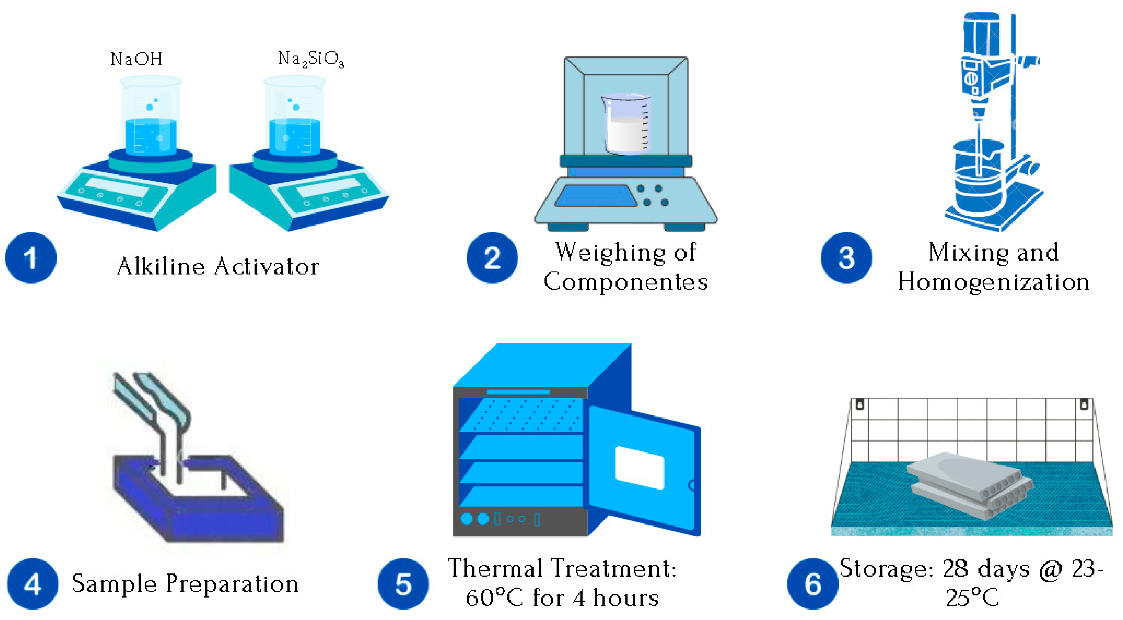
Figure 1 presents the methodology for the synthesis of space geopolymers.
The more detailed experimental methodology can be explained in three general stages, which are described below:
STAGE I. Preparation of the Alkaline Solution (
Figure 2).
A solution of NaOH is prepared in distilled water until a molarity M = 10 is obtained. The addition process is carried out under constant stirring and in an extraction hood, considering that an exothermic reaction occurs.
Simultaneously, Na2SiO3 is prepared in distilled water, under constant stirring, and at room temperature until a homogeneous solution is obtained without visible precipitates. Na2SiO3 in solution is 40 g per 100 mL of water.
The solutions are left to stand for 24 h, avoiding possible effects on the reaction speed due to the heat released by the solutions, as the NaOH solution in water causes an exothermic reaction.
Finally, a new solution of both is prepared by adding Na2SiO3 in NaOH dropwise under constant stirring until a Na2SiO3/NaOH ratio = 0.75.
STAGE II. Preparation of space geopolymer pastes (
Figure 3).
MK and Alkaline Solution components are weighed in the necessary quantities to obtain S/L ratios = 0.65, 0.75, and 1.0, which refers to higher metakaolin content as S/L increases.
The components are incorporated and mixed for 3 min at 300 rpm until the paste is homogenized.
The specimens are cast molded.
Start the evaluation of the space geopolymer pastes.
Stage III. Obtaining the space geopolymers in solid state: Testing samples (
Figure 4).
After 24 h at room temperature, the test specimens are unmolded.
A drying treatment is applied at 60 °C for 4 h to eliminate excess moisture and promote resistance at early ages.
The specimens are stored for 28 days at room temperature (23–25 °C), and relative humidity of 60%, until completely set.
The tests and analyses are carried out to evaluate the solid aerospace geopolymers.
2.2. Rheological Behavior
The rheological properties of the geopolymers were measured on an Anton Paar MCR-302 rheometer (Anton Paar GmbH, Graz, Austria) equipped with a 25 mm diameter parallel plate system. The parallel plates are made of stainless steel to minimize unwanted reactions during the measurement. The rheological evaluation was carried out at room temperature (25 °C) and with a separation between the plates of 2 mm. Data were recorded with Rheo Compass1.25 software.
Rheological measurements in the liquid state were carried out 5 min after the preparation of the space geopolymers, allowing adequate mixing and the evaluation of chemical reactions at early ages. Three tests were carried out to verify the repeatability of the measurements.
The flow curves were determined using a sweep shear rate of 0.1 to 100 s−1. The minimum time per step was 30 s and adjusted according to the shear rate to ensure a steady state.
The amplitude scan to determine the viscoelastic properties of the geopolymers was performed using a frequency of 1 Hz and a strain range of 0.00001 to 100%. This range is suitable for obtaining the viscoelastic linear region and evaluating the loss modulus (G′) and storage modulus (G″) curves.
Finally, an analysis of viscosity concerning time was developed. The cutting rate was kept constant at 1 s−1 for 2 h. The selected time is shorter than the initial setting time and is considered ideal according to the processing of ceramic and cementitious materials.
2.3. Vicat
The Vicat test was developed based on the provisions of the ASTM C191-19 standard. This test is helpful from the point of view of determining the working window offered by a particular formulation. Geopolymers are materials whose properties are time-dependent, and their fluidity behavior varies concerning time. For this reason, it is necessary to determine the time that can be worked under optimal fluidity conditions, which allow casting, extrusion, deposition, and other processes to be carried out.
A manual Vicat needle apparatus (ALCON, Guadalajara, México), with a 1 mm-diameter needle, was used to determine the geopolymers’ initial and final setting time. The test consists of measuring the ability of a needle to penetrate the geopolymer concerning time. The initial setting occurs when the needle penetrates less than 4 mm of the geopolymer. The final setting occurs when the needle penetration is equal to zero, which implies that the geopolymer is in a solid state.
2.4. Dimensional Analysis
The dimensional analysis was developed considering the possibility of shrinkage due to moisture loss. Cylindrical samples were prepared with an approximate diameter of 32 mm and height of 22 mm, defined as the specimens’ initial dimensions. Measurements were taken after 24 h, 48 h, 7 days, and 28 days, the time established for final setting. For this purpose, a vernier was used. Each change in the dimensions of the specimen was reported as a percentage of shrinkage, according to Equation (1):
where
Vii, is the initial volume of the specimen, calculated from its initial dimensions;
Vf, is the final volume of the test tube, obtained from its dimensions in the last measurement (28 days).
2.5. Density
The density of the space geopolymers was determined using the geometric method, which consists of determining the density from the general equation for density:
where
ρ is the specimen’s density;
m is the mass in g of the test tube; and
V is the volume of the specimen, calculated from its dimensions.
A ZEISS SteREO Discovery V8 optical microscope (Carl Zeiss SMT, Oberkochen, Germany) and a high-resolution ZEISS Axiocam 105 Color camera (Carl Zeiss SMT) were used to measure the specimen dimensions. The weight of the specimens was obtained in an OHAUS-Pioneer PA214 analytical balance (OHAUS Corporation, Parsippany, NJ, USA), with an approximation of 0.0001 g.
2.6. Panel Fabrication for Cubesats and P-POD
The main target of the designed geopolymers is to fabricate panels for space applications. The panels with dimensions of10 × 10 cm and 15 × 10 cm were fabricated for the Cubesat and P-POD structures respectively. These panels are too thin so a different fabrication approach is needed, in comparison with the standard testing samples. Geopolymer panels were manufactured by compression molding, using 300 × 300 mm rectangular MDF molds and absorbent fabric to remove moisture from the material. A layer of absorbent fabric was placed at the base of the mold. Subsequently, the geopolymer paste was placed and distributed homogeneously on the plate, using a syringe and a plastic spatula to obtain a homogeneous thickness and a smooth surface. A layer of absorbent fabric and the lid were placed to close the mould, leaving a sandwich-type arrangement. The mould was placed in a hot plate press at 60 °C for 4 h, with a pressing load of 3 tonnes. The geopolymer panel was removed and placed in a Memmert environmental chamber at room temperature (23 °C) and 40% HR for 28 days. Finally, the panels were placed in the CubeSat and P-POD structures to check the ease of handling and placement.
3. Results
Figure 5 presents the development of geopolymers according to the methodology for synthesizing geopolymers.
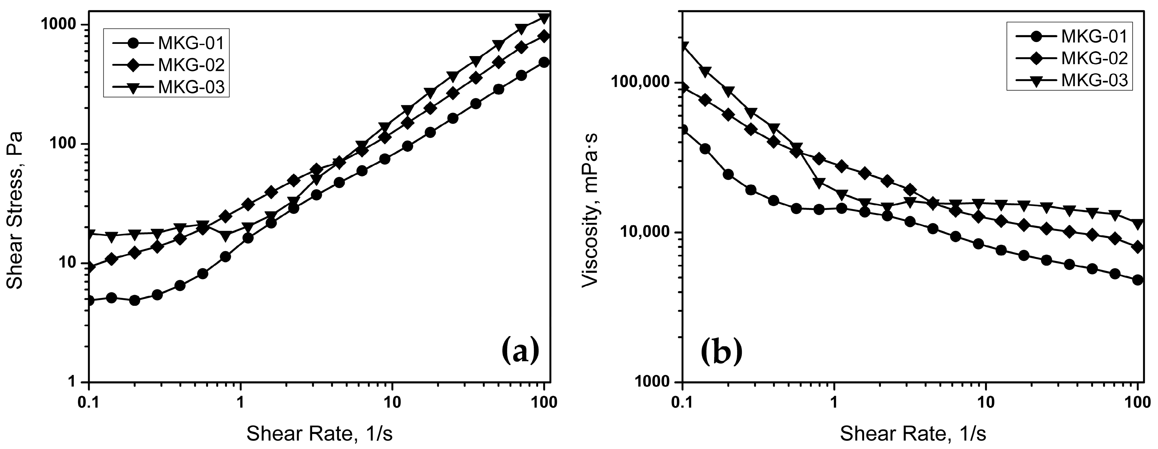
Figure 6 presents the flow curves of geopolymers with different solid/liquid (S/L) ratios. As seen in
Figure 6a, the applied shear stress,
τ, increases with the increase in the shear rate,
γ. On the other hand, the viscosity,
η, decreases as
γ increases (
Figure 6b). The previous could indicate that as
τ increases,
η decreases, which is a classic behavior of slimming fluids. In this sense, having a thinning matrix may be a suitable option for processing. This interaction can facilitate the preparation of specimens after the mixing process because shear stress is applied to produce a homogeneous mixture, and immediately afterward, the viscosity is such that the casting process is simpler.
On the other hand, the viscosity is lower as the S/L ratio decreases, which implies that the viscosity is highly dependent on the amount of alkaline activator included in the geopolymer composition. This effect is consistent with what is expected for a cementitious material, where the increase in the S/L ratio translates into a lower moisture content, which promotes a lower flow, that is, an increase in viscosity. This increase in viscosity translates into lower workability and, consequently, high dispersion and deposition difficulties. Therefore, the flow curves obtained indicate that the MKG-01 sample is the most suitable for processing because the lowest viscosity requires low shear stress.
Finally, an important observation is about the presence of a particular behavior for the MKG-03 sample, at the range of 1–10 s−1. At all the evaluated range, the viscosity and shear stress of MKG-03 is higher, except for these values, where there is a drop in both curves, falling under the curves of MKG-02. These variations in MKG-03 might be attributed to the structural properties of the sample. When applying a certain amount of stress, the sample presents an ordinary thinning behavior, however, when reaching a certain shear rate, the applied stress is sufficient to cause an internal break, leading to a decrease in viscosity and shear stress. Afterwards, the internal structure tends to rearrange by the continuous motion produced by the applied stress, shown by the increment in viscosity.
The amplitude sweep test allows determining the evaluated geopolymers’ linear viscoelastic range (LVER).
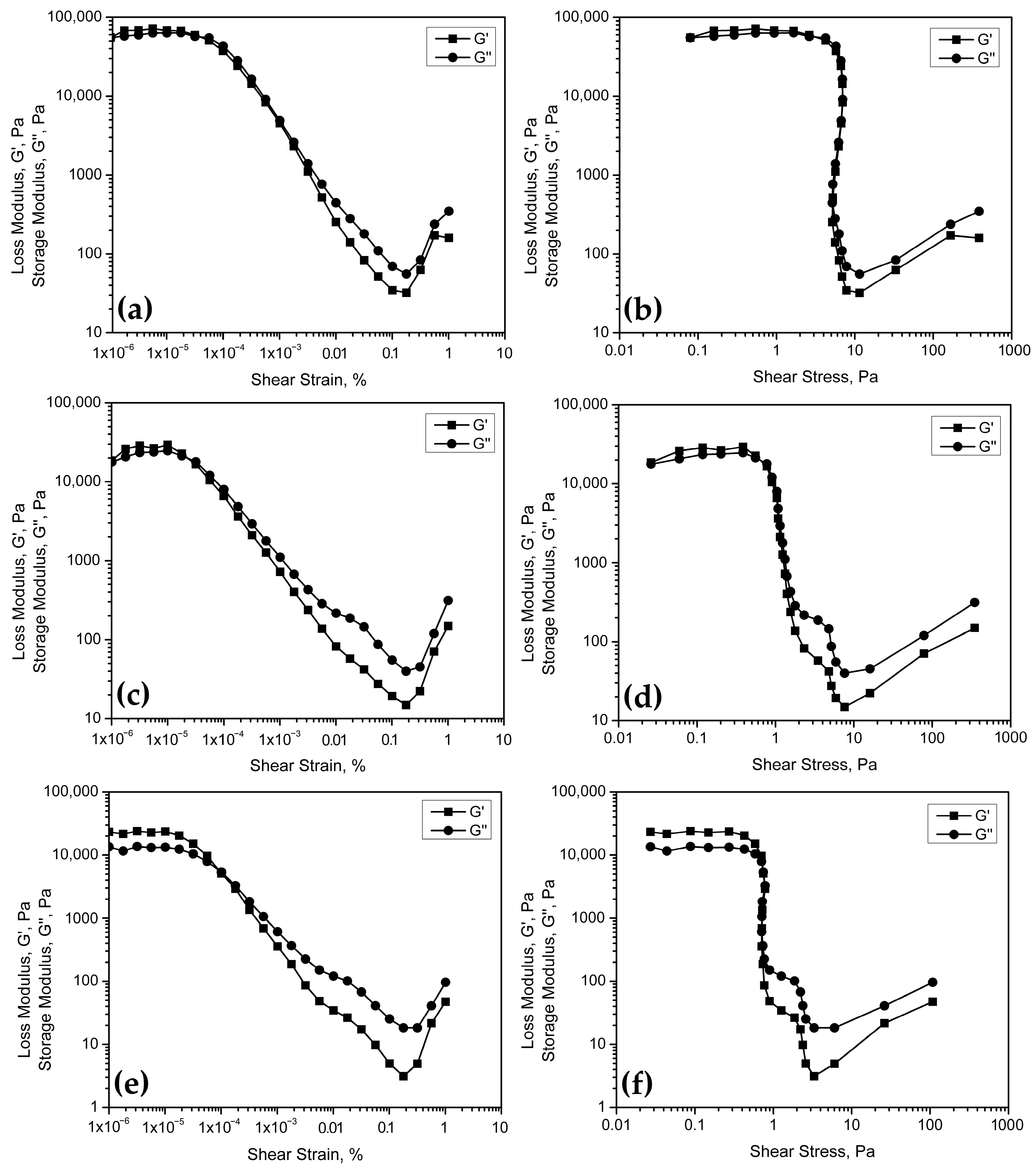
Figure 7 presents the curves of the loss modulus, G′, and storage modulus, G″, as a function of the shear strain,
γ, and the shear stress,
τ.
Figure 7a shows that the geopolymers, with a lower S/L ratio, present a viscoelastic behavior, identified by a linear region at the beginning of the curve corresponding to the loss modulus, G′. The total extent of this linear zone corresponds to the LVER and the point at which the slope changes, known as the Limit of the Viscoelastic Region. In the same way, there is a linear zone that encompasses specific stress values (
Figure 7b), for which the material under study remains within the viscoelastic region. This means that there are specific values of deformation and stress, for which the space geopolymer always behaves like a viscoelastic fluid. An advantage of this behavior is that, as long as it is maintained under the conditions of the LVER, it can flow adequately but without altering its structural properties, that is, without losing the ability to maintain its shape and properties after applying a deformation or stress.
On the other hand, geopolymer pastes made with an S/L ratio = 0.75 do not present the viscoelastic region for any value of deformation or stress (
Figure 7c,d), which translates into uniform behavior, either as a solid or liquid, regardless of the stresses applied.
Likewise, the formulation with S/L = 1.0 (
Figure 7e,f) does not present a viscoelastic region and, in addition, there is a greater separation between the curves G′ and G″, indicating a greater tendency towards solid behavior, which is coincident with its composition, with a higher content of metakaolin powder. In the case of the developed space geopolymers and knowing their viscosity in the fresh state, a behavior with a tendency towards the solid state is expected, which promotes a more complicated deposition and dispersion concerning materials with a lower S/L ratio.
Lastly, the MKG-03 presents the lower values for G′ and G″, and they are obtained at the smaller shear rate. This behavior indicates that MKG-03 allows lesser deformation without structural changes. When reaching a certain amount of deformation, the internal structure breaks and the energy inside the sample tends to diminish. The loss of energy is represented by the lower values of G′ and G″. The results of this technique coincide with what was observed when obtaining the flow curves, where the MKG-03 formulation offers the worst results considering the ability to bear the applied stress and, on the other hand, MKG-01 presents the best conditions for processing.
In addition to the previous measurements, a study of the evolution of viscosity concerning time was carried out, which can be a first approximation for determining the working window offered by each sample. The previous helps to identify significant changes in viscosity at early setting ages.
Figure 8 presents the viscosity curves concerning time for the space geopolymer samples with different S/L ratios, with MKG-01 = 0.65, MKG-02 = 0.75, and MKG-03 = 1.0. As can be seen, up to 3600 s (1 h), there are no significant changes in viscosity for any of the formulations, as long as the shear rate is kept constant. The previous implies that, as long as the paste is maintained in a dynamic state, its flow properties remain unchanged during this period. Furthermore, the MKG-01 sample presents the lowest viscosity values over time, which indicates that it is the best option for processing from the point of view of the viscosity of the materials tested.
Considering the space applications for these geopolymers, a work period of one hour is adequate for processing. In this sense, it is established that all formulations comply with the minimum work window for their processing, handling, or molding. From the point of view of the working window offered by the space geopolymers in a fluid state, the three samples evaluated can be applied efficiently since the working time does not present a significant limitation according to the results obtained. However, to decide the best option regarding the desired working time, it is necessary to complement the results with a Vicat test to determine the setting time.
The Vicat test is essential to evaluating geopolymer pastes in the fresh state. As mentioned above, the flow properties of this type of material are lost over time, so it is essential to know the moment at which these characteristics begin to change. This test presents the initial setting time, the moment the properties change.
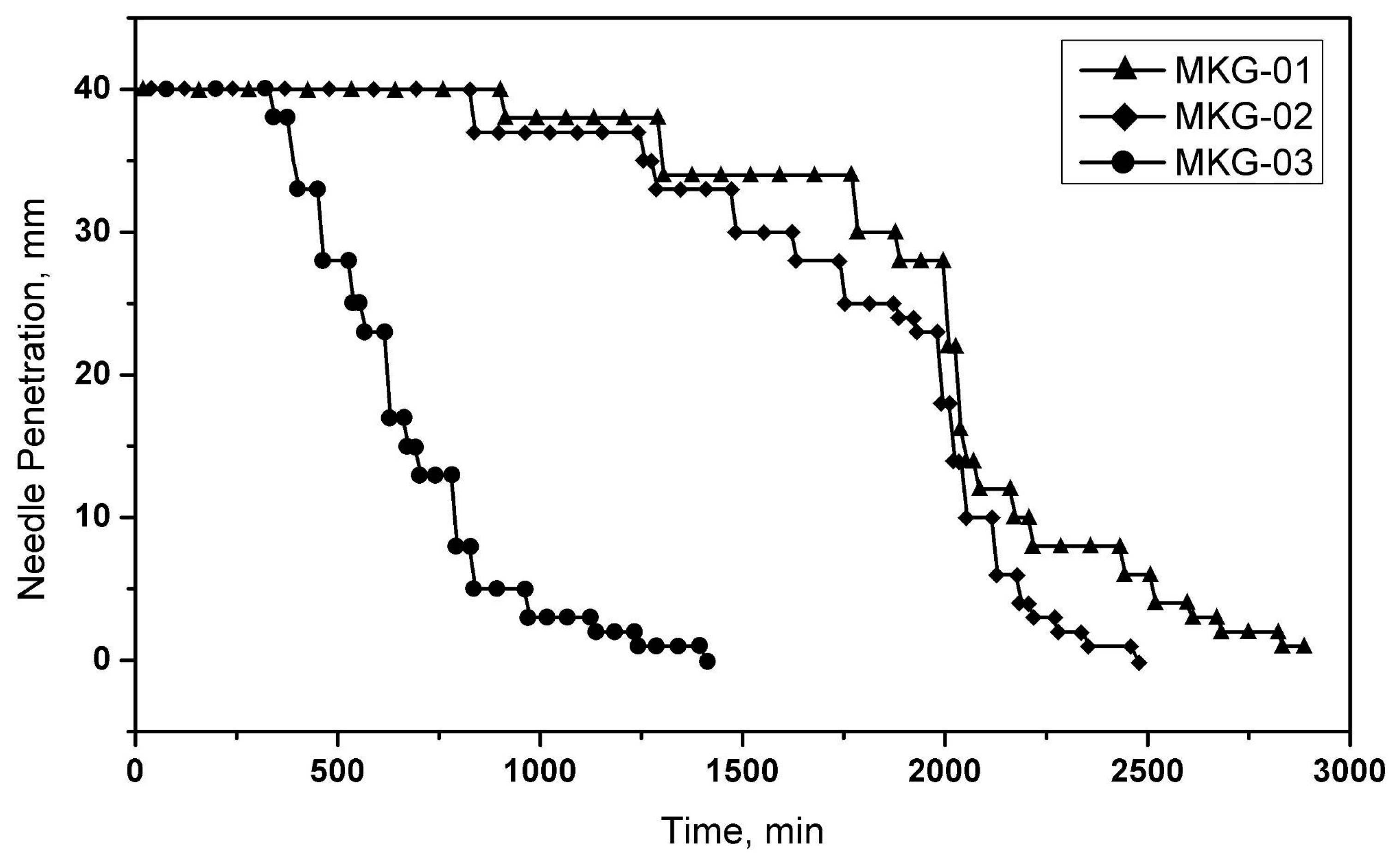
Figure 9 presents the curves obtained by applying the Vicat test. As can be seen, the composition of the manufactured space geopolymers significantly influences the initial and final setting time. For geopolymers with a higher S/L ratio (S/L = 1.0), the setting time decreases considerably, while the opposite case, S/L = 0.65, extends greatly. The previous coincides with what has been reported by various authors regarding the behavior of geopolymers in the fresh state, where the alkaline solution’s content effectively affects the setting time. Furthermore, this is a characteristic behavior of materials with cementitious properties, which are highly sensitive to changes in moisture content.
On the other hand, the considerable changes in the setting time can mean a disadvantage from the point of view of the final application of the space geopolymer since a longer setting time can translate into a higher rate of contraction and, therefore, a decrease in its mechanical properties. That is the main reason the design of space geopolymers requires the previous evaluation by using an oven drying stage to eliminate moisture in a shorter time, thus avoiding contraction due to prolonged setting time. However, this temperature should be as low as possible because it can generate excessive moisture loss, promoting high shrinkage rates and causing surface cracking.
From the results obtained in the Vicat test, it is established that all the samples offer a relatively wide working window, given that the maximum penetration (40 mm) occurs over several hours. However, it is crucial to carry out an adequate evaluation for the application of conditioning in a drying oven to promote the acquisition of strength at earlier ages to allow adequate handling of the manufactured specimens.
Table 1 presents the values obtained from the dimensional analysis of the geopolymer samples with different S/L ratios. As can be seen, after the first 24 h, there is a decrease in the dimensions of the manufactured specimens. This behavior is characteristic of materials with cementitious properties, which begin to lose moisture during the setting process, generating geometric contraction. According to this behavior, the degree of contraction is directly related to the amount of liquid that is included in its composition, as corroborated by the data obtained, where the lowest contraction at 24 h is presented for the sample with ratio S/L = 1.0, corresponding to the lowest alkaline activator content.
On the other hand, it is observed that the most significant contraction occurs during the first 48 h. Subsequently, although there is still a slight degree of contraction at seven days, the changes are practically negligible until 28 days. This trend is typical for this type of material since most of the moisture is lost in the first hours of setting and during the oven drying treatment. Therefore, as there is a small amount of moisture in the later stages, the contraction generated by this effect is lost over time.
Table 2 presents the shrinkage percentage based on the analyzed specimens’ calculated volume. As can be seen, the highest percentage of contraction occurs in sample MKG-01, with a higher content of alkaline activator. On the other hand, sample MKG-03 presents only 9% shrinkage, which is very low compared to formulations with a lower S/L ratio.
The above would indicate that the S/L ratio significantly affects the dimensional stability of the space geopolymers, which is essential to consider during the panels manufacturing for CubeSat and P-POD to avoid design errors.
The density considerably influences the viability of the geopolymers used for aerospace applications. Materials with applications in the aerospace industry must be light to reduce the payload, but high resistance is also required. Both are affected by the density of the material.
The volumetric method considers the geometric dimensions of the sample and its mass for a general calculation of density.
Figure 10 presents optical microscopy images of the measurement of the geometric dimensions of the specimens. This measurement was carried out in order to obtain more precise results. Likewise,
Table 3 presents the data obtained and the calculated density values.
As can be seen, the lowest density occurs for the sample with the lowest S/L ratio (MKG-01) and increases when it is higher. It is explained from the point of view of the air content trapped in the geopolymer matrix. As the amount of alkaline activator in the formulation increases, more bubbles and trapped air appear, decreasing the manufactured specimen’s density. On the other hand, when the amount of solid is higher, the alumino-silicate chains that are formed are shorter and tend to compact better, promoting better particle arrangement and greater density.
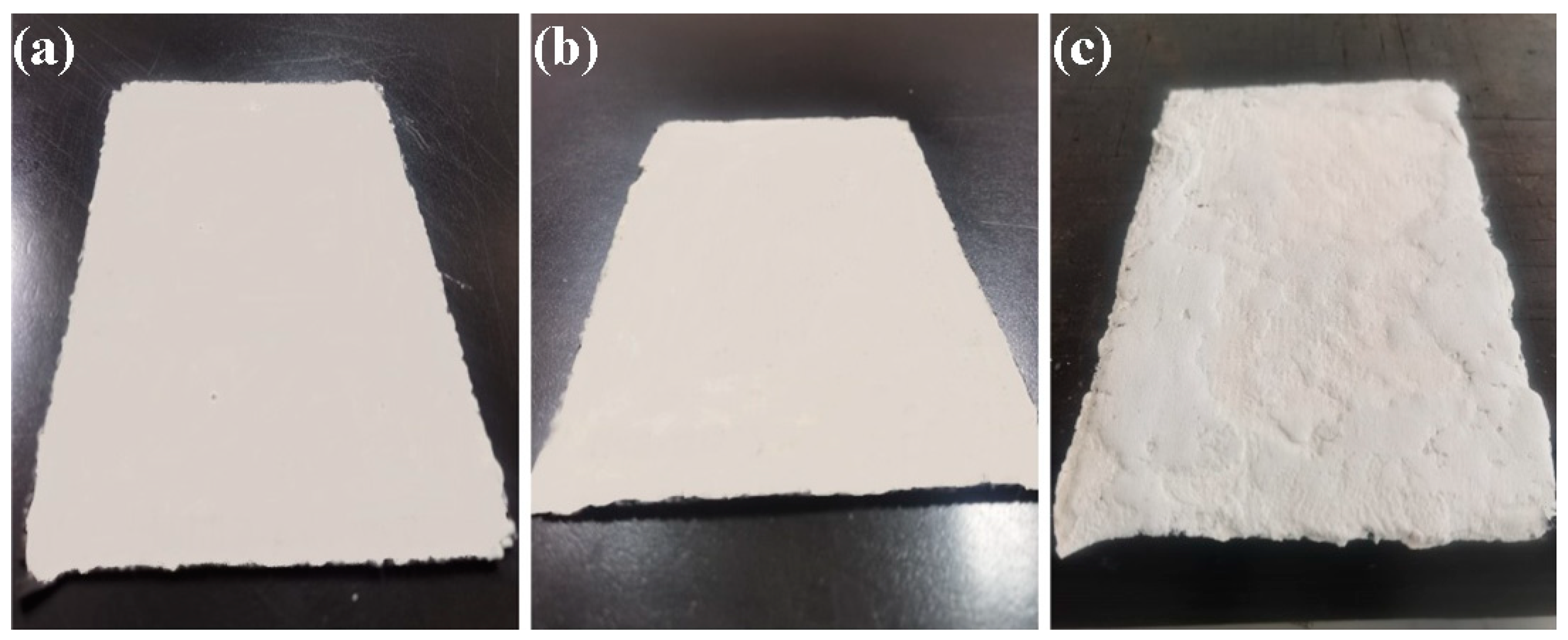
Figure 11 presents the geopolymer panels. As can be seen, the panels manufactured with the MKG-01 and MKG-02 formulations (
Figure 11a,b) present a homogeneous surface without apparent defects. However, the ends of the panels showed cracks. The cracks were caused by the shrinkage of the geopolymers, which led to a heterogeneous thickness along the spatial geopolymer panels. In this way, the ends of the panels turned out to be thinner (1.2 mm) than the center of the panels (1.5 mm). Despite the imperfections above, both formulations appear suitable for fabricating panels for the CubeSat and P-POD chassis. On the other hand, sample MKG-03 (
Figure 11c), which has a higher viscosity and, consequently, lower malleability, presents a surface with reliefs due to the difficulty of distributing the geopolymer homogeneously. Therefore, the high density of the MKG-03 formulation prevents the fabrication of nanosatellite panels.
MKG-01 and MKG-02 formulations are less viscous and, therefore, easier to handle and mold. The opposite occurs with MKG-03, with the highest viscosity, it is difficult to work. Considering the results obtained and the malleability to manufacture the panels, the MK-G01 formulation provided the best results for manufacturing geopolymer panels.
Figure 12 The CubeSat and P-POD structures containing the geopolymer panels are presented. In a previous research work [
20], the geopolymers MKG-01, MKG-02, and MKG-03 were evaluated, which showed high fire resistance and thermal stability and acted as efficient shields against cosmic radiation. However, the geopolymer panels are very fragile and complex to manipulate or mold.
4. Conclusions
Geopolymers for space applications were successfully formulated to fabricate panels for the CubeSat and P-POD chassis.
The formulations of the geopolymers MKG-01, MKG-02, and MKG-03 balance fluidity and malleability suitable for manufacturing the panels of the nanosatellite and P-POD structures.
The viscous properties of the geopolymers are considerably affected by the content of the alkaline activator. When increasing its content the viscosity greatly diminishes. Also, the viscoelastic behavior of the geopolymers present a significant change as the alkaline activator varies.
Changes in the viscosity of the geopolymers produce variations on the fabrication process of the panels. Low viscosity geopolymers are more suitable for fabrication. As the panels are too thin, the higher viscosity does not allow an homogeneous deposition of the geopolymer, giving a panel with inconsistencies in thickness. Consequently, formulation MKG-01 offers better results when fabricating panels, by only considering its viscosity.
Also, variations in the viscoelastic behavior produce different results for panel manufacturing. A geopolymer with a viscoelastic range at lower strain represents a lower stress applied and, consequently, an easier deposition of the geopolymer and easier manufacturing. MKG-01 corresponds to the formulation with the better viscoelastic behavior to fabricate aerospace panels.
Geopolymer formulations for space applications offered an open window of approximately 8 h. This working time is adequate as it gives the opportunity to manufacture the aerospace panels without losing its fresh properties during the process.
All formulations lost a relevant mass content closely related to the S/L ratio of the formulation, so the higher the alkaline activator content, the greater the fragility of the geopolymer. Also, the more complicated the panel manufacturing, as it tends to break due to its fragility altogether with the small thickness.
The MKG-01 geopolymer panels were successfully integrated into the CubeSat and P-POD chassis.
The formulated geopolymers are slightly brittle, so we are working on reinforcement strategies with carbon fiber and basalt fabrics.
