1. Introduction
Ceramics are widely known materials exhibiting various unique properties. In this regard, these materials are attractive in applications associated with high requirements for mechanical strength, temperature stability, and optical transparency in the end products. Among other materials, ceramics based on magnesium oxide (MgO) have the complete combination of the listed features [
1]. This material is widely used in various industries due to its temperature [
2] and corrosion [
3] resistance. MgO ceramics are employed in the production of medicines as well [
4]. Other applications include the production of insulating materials [
5], mineral fertilizers [
6], water treatment chemicals [
7], and protective coatings for electronic devices [
8].
Finely dispersed powders are the main raw materials for producing ceramic products based on MgO. Various methods are used to obtain such powders. One of the most common approaches is the mechanochemical method based on grinding the feedstock to a finely dispersed mixture in ball mills [
9]. The other is spray pyrolysis, in which metal salt compounds are thermally sprayed, followed by the formation of metal oxide particles [
10,
11]. It is worth noting other alternative methods for obtaining ceramics of this type, including the sol–gel method [
12], chemical vapor deposition (CVD) [
13], pulsed laser deposition [
14], and laser ablation [
15].
Due to its simplicity, efficiency, and economy, the electroerosive method is widely used to obtain metal oxide nanopowders. The methods of ion [
16] and electric arc sputtering [
17] are mainly used. In the first case, ions extracted from the gas discharge plasma bombard a metal target (a cathode), leading to the removal of metal atoms from it. During arc sputtering, the erosion of an electrode under negative potential occurs as a result of the formation of the cathode spots, which are elementary sources of plasma and cathode material vapors [
18]. If the arc discharge is supported by thermoelectronic emissions from a hot cathode, then an anode of the arc discharge is subjected to thermal erosion. The ion sputtering method can only be used at lower gas pressures. At low pressures, ions can gain an energy of several hundred electron volts, which is sufficient to sputter the cathode material. Cathode spark [
19] and arc sputtering [
20] can also be implemented at atmospheric pressure. The mechanism for the generation of particles in the form of a powder is directly related to the triggering and self-sustaining of the discharge as a result of the destruction of microprotrusions on the cathode surface under the thermal and hydrodynamic effects of explosive electron emissions [
21] and plasma pressure inside cathode spots [
22].
Spark discharge as a method of producing powders is well known and widely used in practice [
23]. Its advantages lie in the extreme simplicity of the discharge assembly, formed by only two electrodes. The discharge assembly is combined with a gas system, including pumps and cylinders with inert or reactive gases. It is known that the spark discharge is a pulsed phenomenon. If a self-breakdown scheme (where overvoltage is provided) of the discharge gap is used, the duration of a spark current pulse is determined by a voltage pulse generator or the parameters of the electrical circuit [
24]. This characteristic can vary from a few nanoseconds to a few microseconds. Thus, if it is possible to adjust the amplitude, duration, and repetition rate of the feed voltage pulses, as well as the amplitude of the discharge current, which can reach several kiloamperes, the thermal regime of the discharge assembly, including the temperature of the electrodes, can be controlled to avoid melting. Nevertheless, even in the case of using electrospark plasma generators consisting of several gaps connected in parallel [
25], this method ensures the production of no more than one milligram of powder material over a sufficiently long time, which is acceptable only for research purposes. It is obvious that the further development of electroerosive methods for the generation of powder materials is required. This will help increase productivity and determine the features of the formation of powder particles, such as during the transition to the arc discharge with a cold cathode, i.e., to a cathodic arc.
This paper is devoted to a study of the operation of a developed three-electrode discharge system designed for the generation of cathodic arc plasma in an argon medium at atmospheric pressure, with a life time of several hundred microseconds and a current amplitude of up to 200 A. The cathodic arc discharge is ensured by an auxiliary discharge formed as a result of the high-voltage breakdown of the interelectrode gap. The developed discharge system is proposed as a promising approach to produce nanopowders based on magnesium oxide.
2. Materials and Methods
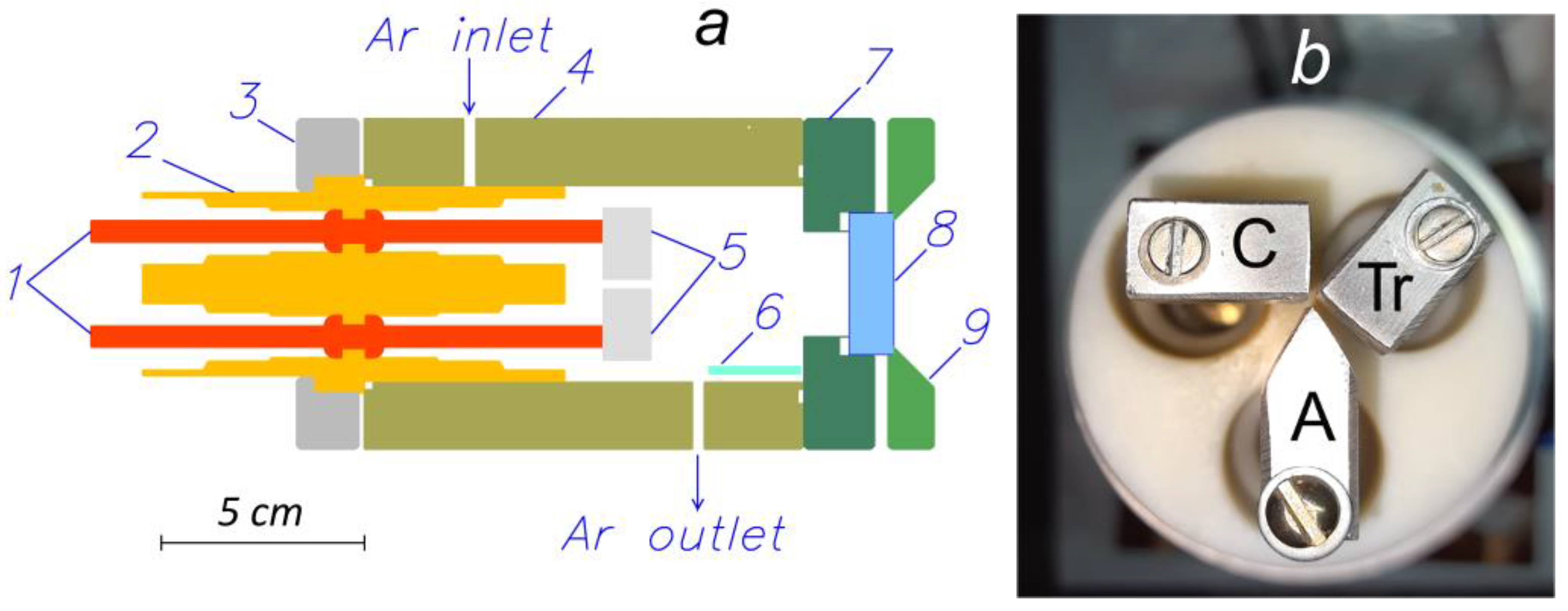
A schematic of a discharge system for the cathodic arc formation is shown in
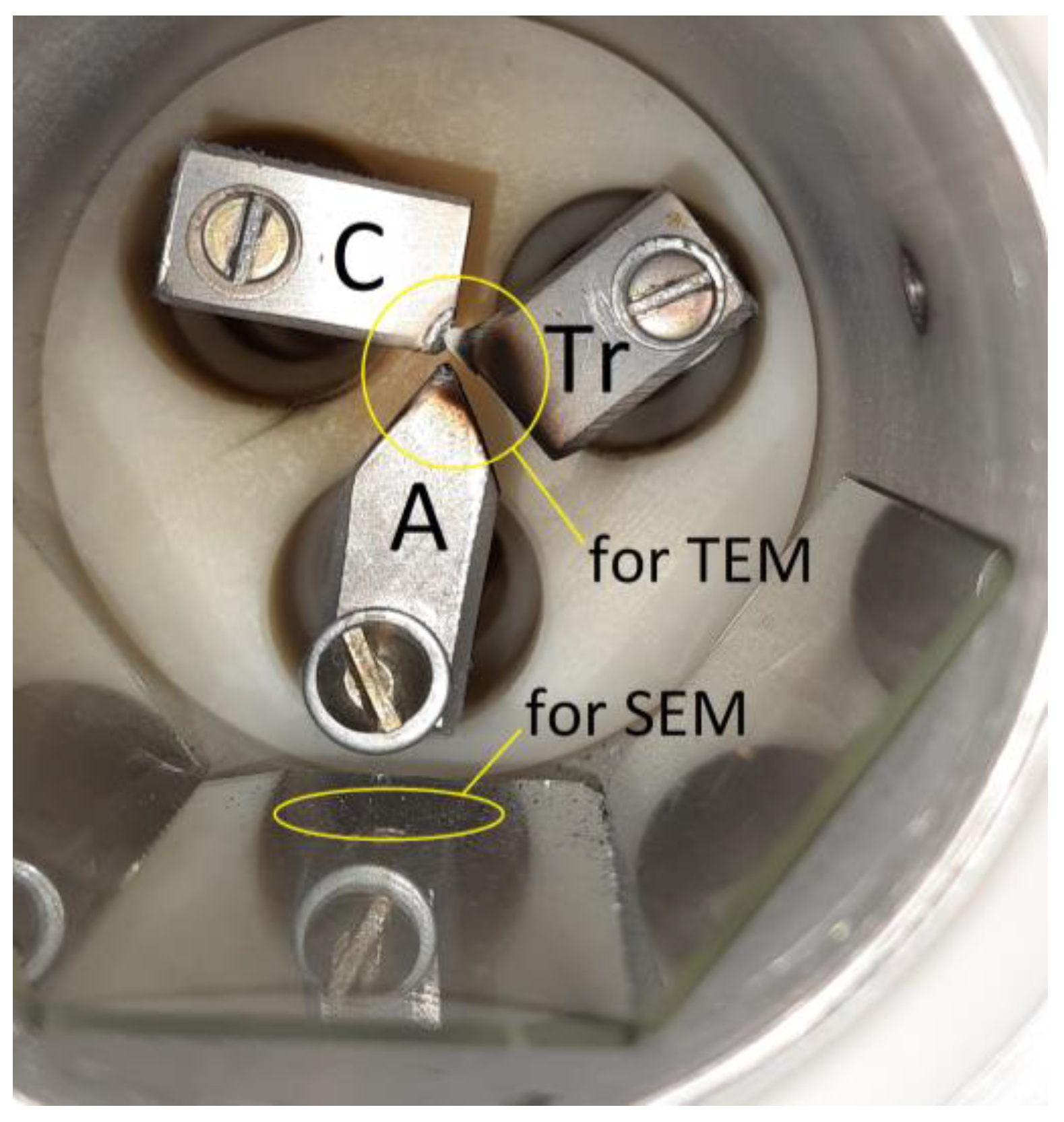
Figure 1a. Brass current leads (1) were mounted inside a polyamide insulator (2), which was pressed by a back-ring clamping flange (3) to a cylindrical aluminum body (4) (discharge chamber) with an inner diameter of 5.5 cm and a length of 12 cm. The elements (5) were electrodes of the discharge assembly. The appearance and actual configuration of the discharge assembly are demonstrated in
Figure 1b. The cathode “C” and an anode of the triggering (auxiliary) discharge “Tr” were parallelepiped-shaped with dimensions of 2 × 1 × 1 cm
3. The anode “A” of the arc discharge (main discharge) was wedge-shaped. This form was optimal from the point of view of stably triggering the pulsed cathodic arc. This was determined empirically as a result of preliminary studies. All electrodes were made from a single piece of a commercial magnesium alloy AM60. According to the manufacture’s certificate, it should contain ~5.5–6.5 mass. % of aluminum and <1 mass. % of silicon. To form the discharge in a gas flow at atmospheric pressure, the chamber was equipped with an input and an output to pump the working gas. Ambient air and argon with a purity of 99.9995 vol.% were used in the experiments. The gas was pumped through the discharge chamber at a rate of 1000 sccm.
The products of the electrode erosion were collected on the glass substrate (6), which was mounted on the inner surface of the body (4). The distance from the ends (facing the reader) of the electrodes (5) to the center of the glass substrate (6) was 3 cm. Visual observations and spectral diagnostics of the optical radiation of the cathodic arc plasma were carried out through a window (8) made of fused quartz. The distance from the ends of the electrodes (5) to the inner surface of the quartz window (8) was 5.5 cm. The overall dimensions of the plasma generator according to the outer protruding parts were 24 cm in length and 9.5 cm in diameter.
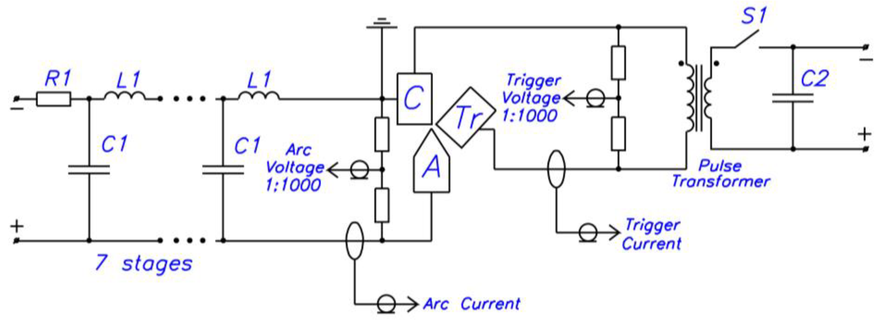
An electrical circuit of the discharge system is shown in
Figure 2. To feed the cathodic arc, a power supply based on a pulse-forming network consisting of seven series-connected
L1
C1 cells was used. A line was charged from a DC source through a ballast resistance (
R1). The auxiliary discharge was fed by a switching power supply based on a storage capacitor (
C2). The source was discharged through a primary winding of a pulse transformer when a thyristor (
S1) was switched on.
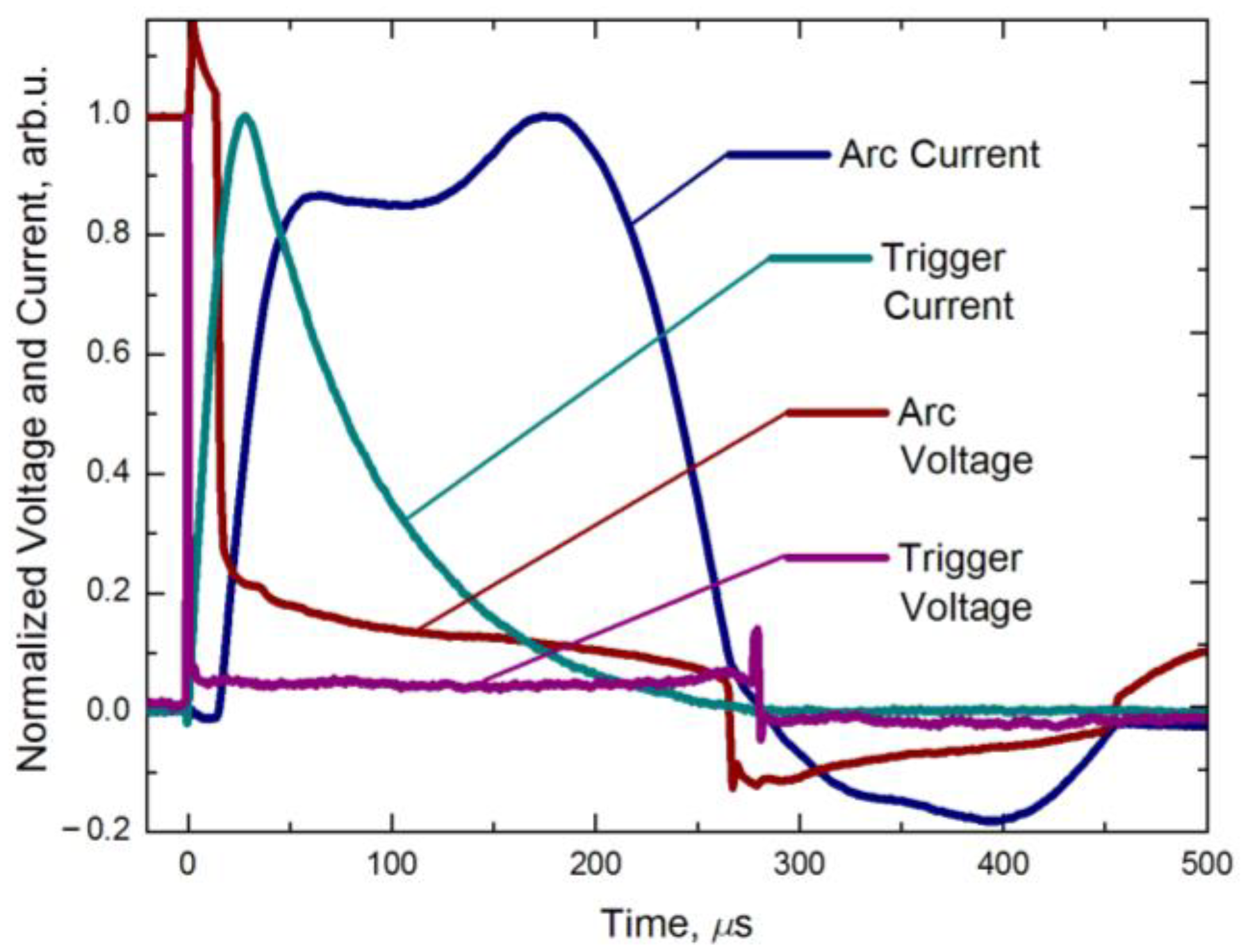
The discharge system operated as follows. A voltage pulse with an amplitude of 10 kV (idle mode) was applied to the 1-mm-wide gas-filled “C”–“Tr” gap. The auxiliary discharge between these electrodes occurred at the voltage of 1200 V (
Figure 3). The electric field strength at this voltage was sufficient to break down this gap. Spots, which were the sources of plasma and neutral particles of the cathode material, appeared on the cathode surface. The auxiliary discharge current reached an amplitude of 20 A after ~28 µs and then dropped to near-zero values within ~300 µs. At the same time, the voltage of this discharge did not depend on the discharge current and amounted to 18 ± 3 V. This fact provides indirect confirmation of the quasi-stationary mode of the arc discharge with cathode spots, with the so-called “cold” cathode, when the main process of maintaining the discharge is explosive electron emission [
26].
An idle voltage of 200 V (DC) applied to the gap was not enough for a self-sustained breakdown. The auxiliary discharge plasma was a source of charged particles and high-energy photons, which together contributed to the breakdown of the “C”–“A” gap, after which the power supply ensured a current pulse with a duration of 250 μs. It should be noted that the main discharge between electrodes “C” and “A” was triggered with some delay, which varied from pulse to pulse in the range of 10–50 µs.
To measure the electrical parameters of the discharge, Pearson (Pearson Electronics, Palo Alto, CA, USA) current monitors with a sensitivity of 100 A/V were embedded in the circuit of the anodes of the main and auxiliary discharges, as well as Pintek HVP-28HF (Pintek Electronics, New Taipei City, Taiwan) high-voltage dividers with a division ratio of 1:1000, which were connected in parallel to the discharge gaps. The dynamics of the discharge parameters were recorded with a MSO5204 (Rigol Technologies, Co., Ltd., Suzhou, China) digital real-time oscilloscope.
To analyze the spectral composition of the optical radiation of the cathodic arc plasma from the gap between magnesium electrodes, an HR2000 + ES (OceanOptics Inc., Orlando, FL, USA) compact optical spectrometer operating in the wavelength range of 200–1100 nm with a spectral resolution of ~1.2 nm was used. The plasma emission was transmitted to the input of the spectrometer via a flexible fiber, the input aperture of which was located in the immediate vicinity of the quartz window outside the discharge chamber. If necessary, the radiation intensity was attenuated using a mesh filter with an optical transparency rate of about 8%. For all elements of the optical measuring system, there were dependencies of the transmittance and sensitivity on the wavelength, provided either by the manufacturer of the device or measured in-house using well-known methods and calibrated radiation sources. The spectrometer was calibrated on the wavelength scale using the reference spectra of low-pressure argon–mercury or mercury–helium lamps. The spectral lines of magnesium atomic particles in the discharge plasma were identified using the NIST database (National Institute of Standards and Technology, Gaithersburg, MD, USA) [
27].
The erosion products of the Mg electrodes, namely a layer of nanoparticles or powder deposited on the electrodes of the discharge assembly, glass substrates, and inner cylindrical surface of the body of the discharge chamber, were analyzed. A mixture of powder particles was dispersed in a solution of distilled water (~20 mL) using an ultrasonic treatment until a homogeneous suspension was obtained. Then, the dispersed mixture was deposited onto the carbon-coated copper grids. The structure of the particles produced as a result a erosion of Mg electrodes exposed to the cathodic arc at atmospheric pressure in an argon flow was studied using a JEM 2100 (Jeol, Tokyo, Japan) transmission electron microscope (TEM) at an accelerating voltage of 200 kV. The phase composition was determined by analyzing a series of selected area (electron) diffraction (SAED) and nano-beam diffraction (NBD) patterns at electron probe diameters of 700 nm and 10 nm, respectively.
The elemental composition of the particles was determined by the energy-dispersive analysis (EDS). Using an INCA Energy (Oxford Instruments, Les Ulis, France) EDS spectrometer mounted on a TEM, we obtained spectra exhibiting the K-series of elements (Mg, Al, Si, O, C) from individual particles (point analysis), where the probe beam diameter was ~12 nm, the total number of pulses was ~15,000, the collection time was 70 s, and the dead time did not exceed 10%. The composition of the powder mixture with a larger size (>1 μm) was analyzed via a point analysis using a Hitachi S-3400N (Hitachi Science Systems, Ltd., Ibaraki, Japan) scanning electron microscope (SEM) equipped with a Bruker XFlash 4010/5010 nitrogen-free EDS detector at the accelerating voltage of 20 kV. The morphology of the large (>1 μm) particles was studied with a high-resolution Apreo 2 S field emission SEM (ThermoFisher Scientific, Bleiswijk, The Netherlands) at the accelerating voltage of 20 kV using secondary and backscattered electron detectors.
3. Results
An integrated approach was used to study erosion processes under the action of the cathode arc at atmospheric pressure. Methods based on the analysis of optical radiation spectra of the discharge plasma, as well as electron microscopy of the electrode erosion products, were used. At atmospheric pressure, optical emission spectrometry is practically the only method for revealing the elemental composition of the discharge plasma. Therefore, in the case of a vacuum arc [
28], studying the dependence of the spectral energy density on the radiation wavelength provides detailed information about the presence in the plasma of both positive ions and neutral atoms [
29,
30,
31,
32].
Under the conditions of the experiments, it was possible to implement the following operating modes of the cathodic arc in the three-electrode discharge assembly.
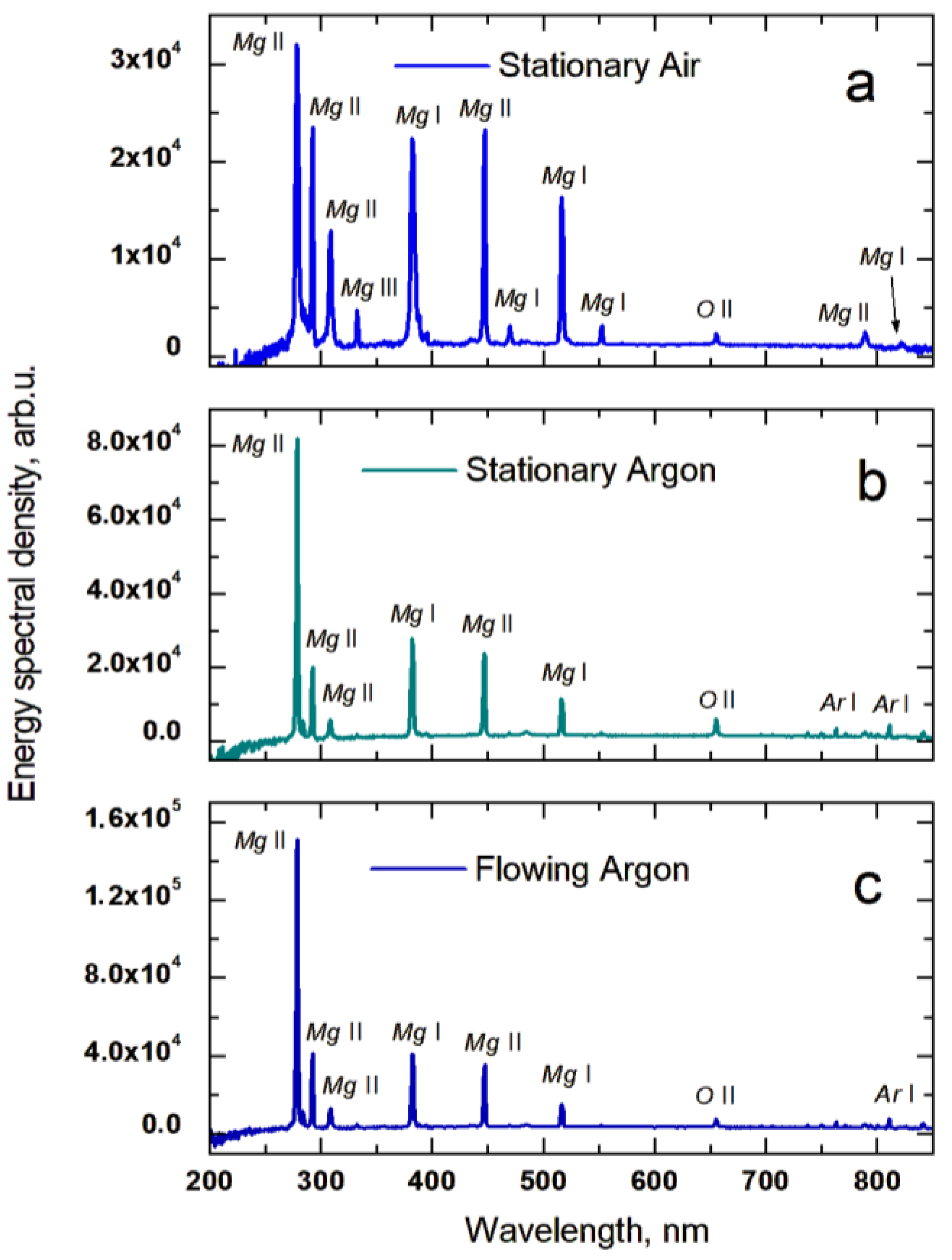
The first mode was tentatively labeled “stationary air” (
Figure 4a). As the label implies, the cathodic arc operated in the static atmospheric pressure air. In this mode, the emission spectrum is represented by lines of a magnesium atom (Mg I (λ = 382.935, 470.299, 516.732, 552.840, 821.303 nm), a singly charged magnesium ion Mg II (λ = 279.5, 292.863, 309.106, 448.132, 787.70 5 nm), and a doubly charged magnesium ion Mg III (λ = 332.106 nm). Some species of the ambient air are also preserved, as confirmed by the presence of the line corresponding to a singly charged ion of atomic oxygen (O II) (λ = 655.014 nm). It should be noted that due to the insufficient spectral resolution (≈1.2 nm), the multiplets of metallic atoms and ions; for example, the Mg II ion doublet in the wavelength range of Δλ = 279.5–280.2 nm or the Mg I atomic triplet in the range of Δλ = 516.7–518.4 nm cannot be deconvoluted into separate lines.
The second mode, “stationary argon” (
Figure 4b), was implemented when the cathodic arc operated in an argon medium at atmospheric pressure. This was ensured by the displacement of air from the discharge chamber by an argon flow and subsequent blockage of the inlet and outlet of the discharge chamber. This mode is characterized by the appearance of lines of argon atoms located at Δλ = 700–900 nm. Among them, the lines of Ar I with the wavelengths of λ = 763.5 and λ = 811.5 nm had the highest intensity levels. A significant decrease in intensity was observed for the lines of the magnesium atom Mg I (λ = 470.299 and 552.840 nm) and the doubly charged magnesium ion Mg III (λ = 332.106 nm). Despite the predominance of the argon concentration in the discharge chamber, the spectrum contains the line of the singly charged ion O II (λ = 655.014 nm), which is comparable in intensity to the lines of Ar I.
The third mode with the continuous flow of argon through the discharge chamber was called “flowing argon” (
Figure 4c). It was characterized by the presence in the plasma emission spectrum of the lines of the same particles that were observed in the “stationary argon” mode (
Figure 4b). The difference consisted of an increase by more than an order of magnitude in the emission intensity of the Mg II line (λ = 279.5 nm).
An important feature of the cathodic arc under the conditions of this study was the stability of its operation in the pulsed mode at pulse repetition rates of up to 10 Hz. Among all three modes, the greatest instability of the main discharge triggering was observed when the discharge system was operating in the “stationary air” mode. Additionally, in this mode, the transition to a DC mode with a current of up to 1 A occurred. This transformation led to uncontrolled thermal erosion of the electrodes. In the static argon (“stationary argon” mode), current pulses of the main discharge were triggered with high stability. However, at the pulse repetition rate of 10 Hz, the discharge could spontaneously transform into a continuous low-current form, as in the “stationary sir” mode. The pumping of argon ensured stable triggering of the main discharge and the absence of transitions to the DC mode. It is obvious that the transition of the cathodic arc to the DC discharge is due to the peculiarity of the power supply, which provides the presence of a constant voltage across the “C”–“A” gap that is able to maintain the DC current. Nevertheless, the influence of the gas kind and the rate of its consumption on the operating features of the cathodic arc are also obvious. Taking into account this fact, the mode with argon flow (“flowing argon”) was chosen as the main one. Thus, the erosion products of the electrodes were collected during the cathodic arc in the argon flow.
The generation of a powder material as a result of the erosion of the Mg-containing electrodes in the cathodic arc plasma in an argon flow at atmospheric pressure was carried out for 2 h at the pulse repetition rate of 10 Hz. After the specified time of ±5 min, a conductive jumper appeared between the cathode and anode of the auxiliary (triggering) discharge due to the accumulation of electrical erosion products. This is noticeable in
Figure 5. Thus, in the electrical supply circuit of the triggering discharge, the cathode and anode turned out to be short-circuited, and applying voltage pulses between them did not lead to the formation of discharge plasma. Consequently, the breakdown of the main discharge gap did not occur and the process of powder generation was interrupted. It is worth noting that the same problem takes place in the coaxial type discharge system [
33], which is used in metal ion sources [
34].
After completing the erosion process, the discharge system was inspected (
Figure 5). There were traces of erosion on cathode “C”. It can be seen from
Figure 5 that they were concentrated at the top of the cathode. The anode “Tr” of the auxiliary discharge was deformed, so a cone-shaped protrusion was formed on its upper surface, located against the eroded section of the cathode. Erosion traces are also visible on the wedge-shaped protrusion of anode “A”. There was a coated layer of a powder on the glass substrate surface, consisting of individual large-size particles visible to the naked eye. The electrodes of the discharge assembly were also coated with fine particles. Based on this experimental fact, for the TEM analysis, the powder mixture was simultaneously gathered from the surfaces of all three electrodes. Larger particles deposited on the glass substrate were examined by SEM (
Figure 5).
The structure of the powder mixture produced as a result of the erosion of the magnesium electrodes during discharge at atmospheric pressure in the argon flow is shown in
Figure 6 and
Figure 7.
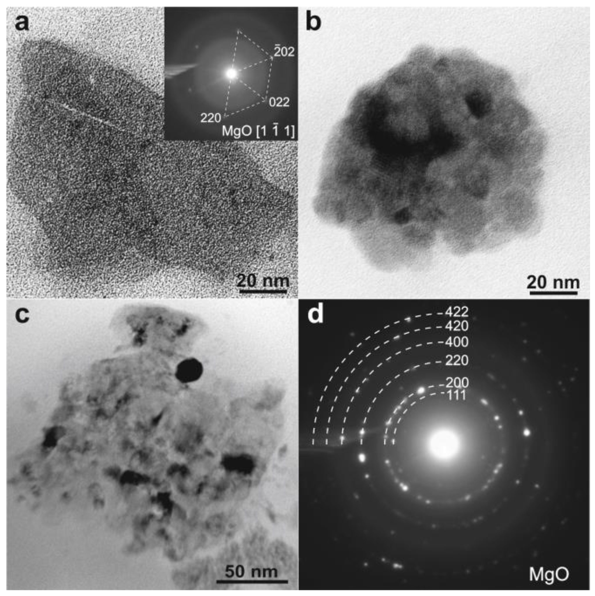
The TEM study of the Mg-containing powder (
Figure 6) revealed individual particles (
Figure 6a) of ~100 nm in size and dispersed nanocrystals (~15–20 nm) assembled into clusters (
Figure 6b,c). The diffraction analysis of the phase composition was performed using the NBD and SAED methods. It was found that both types of synthesized particles were magnesium oxide (MgO) with a face-centered cubic (fcc) lattice described by the Pearson symbol cF8 and the symmetry group Fm-3m (225). The corresponding NBD (inset in
Figure 6a) and SAED (
Figure 6d) patterns confirm the formation of a single-phase structure based on MgO. Moreover, the bright-field images of the smallest particles (
Figure 6b,c) demonstrate presumably the spherical and equiaxed particles without crystalline defects (dislocations). An observable diffraction contrast of the moiré pattern (
Figure 6b) arises from the various orientations of the adjacent nanoparticles. In the largest MgO particles (
Figure 6a), the deformation contrast is very poor, which indicates the defect-free nature of the synthesized powder.
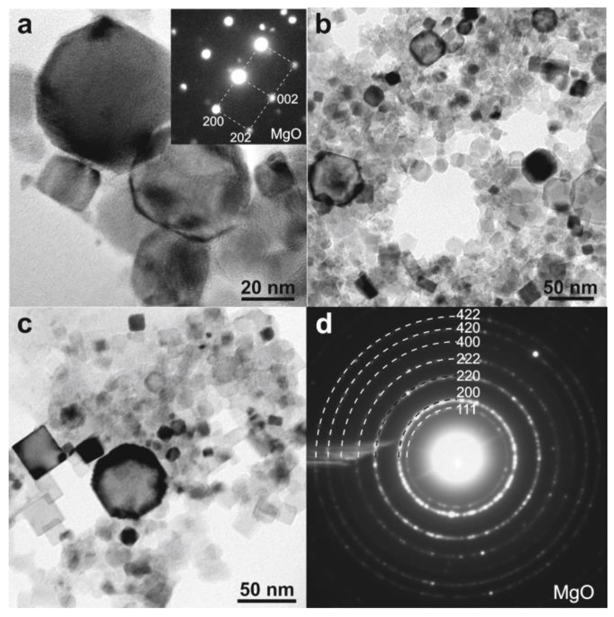
In turn, other structural features of the particles are found in the same powder mixture. Indeed, the images in
Figure 7a–c show bright-field images of the erosion products exhibiting almost perfect nanocubes with sharp edges. The mean size of the synthesized particles is ~40 nm, which is equal to the largest length of the nanocubes. The NBD pattern (inset in
Figure 6a) is characterized by bright diffraction spots corresponding to the {200} and {202} lattice planes of the fcc MgO phase. The SAED pattern (
Figure 6d) demonstrates the solid diffraction rings of the same magnesium oxide (MgO) as found in the Mg-containing powder mixture (
Figure 6d). All nanoparticles are single-crystalline and have the random crystallographic orientation. Taking into account the strict particle boundaries (
Figure 7c) and the absence of structural defects, we suppose the formation of a recrystallized structure induced by a short heat annealing of the particles in the cathodic arc plasma. A similar morphology to the as-synthesized MgO powder was described in [
17], describing the assembled chains of the edge-sharing nanocubes via DC arc discharge.
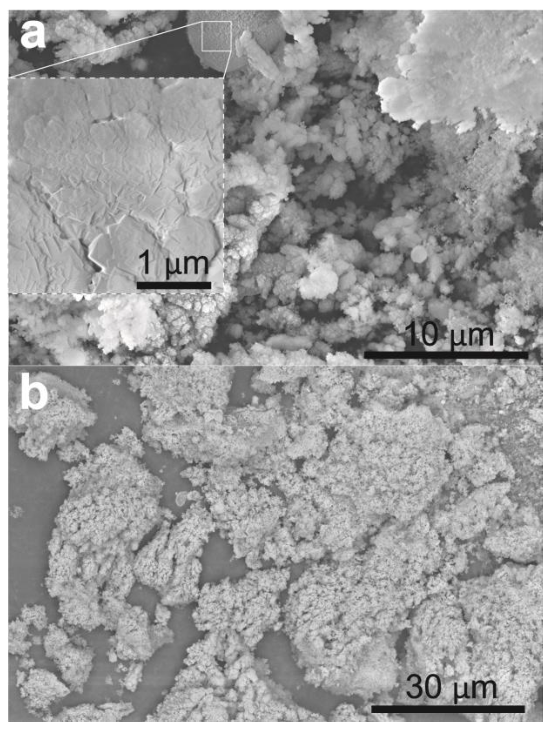
In order to reveal the morphology of the powder conglomerates, the fraction of the powder mixture deposited onto the glass substrate positioned near the walls of the discharge chamber after finishing the pulsed cathodic arc discharge process was analyzed. SEM images of the Mg-containing powder are given in
Figure 8. As one can see, the erosion products are characterized by the net of dendritic crystals (
Figure 8a) as well as the round specks of powder. The droplet has a needle-like morphology (inset in
Figure 8a) formed due to the growth of the close-packed crystal planes. The SEM contrast in back-scattered electrons (
Figure 8b) shows a uniform distribution of the chemical elements over the analyzed surfaces of the powder. The largest fractions of the powder were ~20–30 μm in size and formed, most likely, via coagulation of the smallest dendritic crystals of MgO upon its deposition onto the chamber walls.
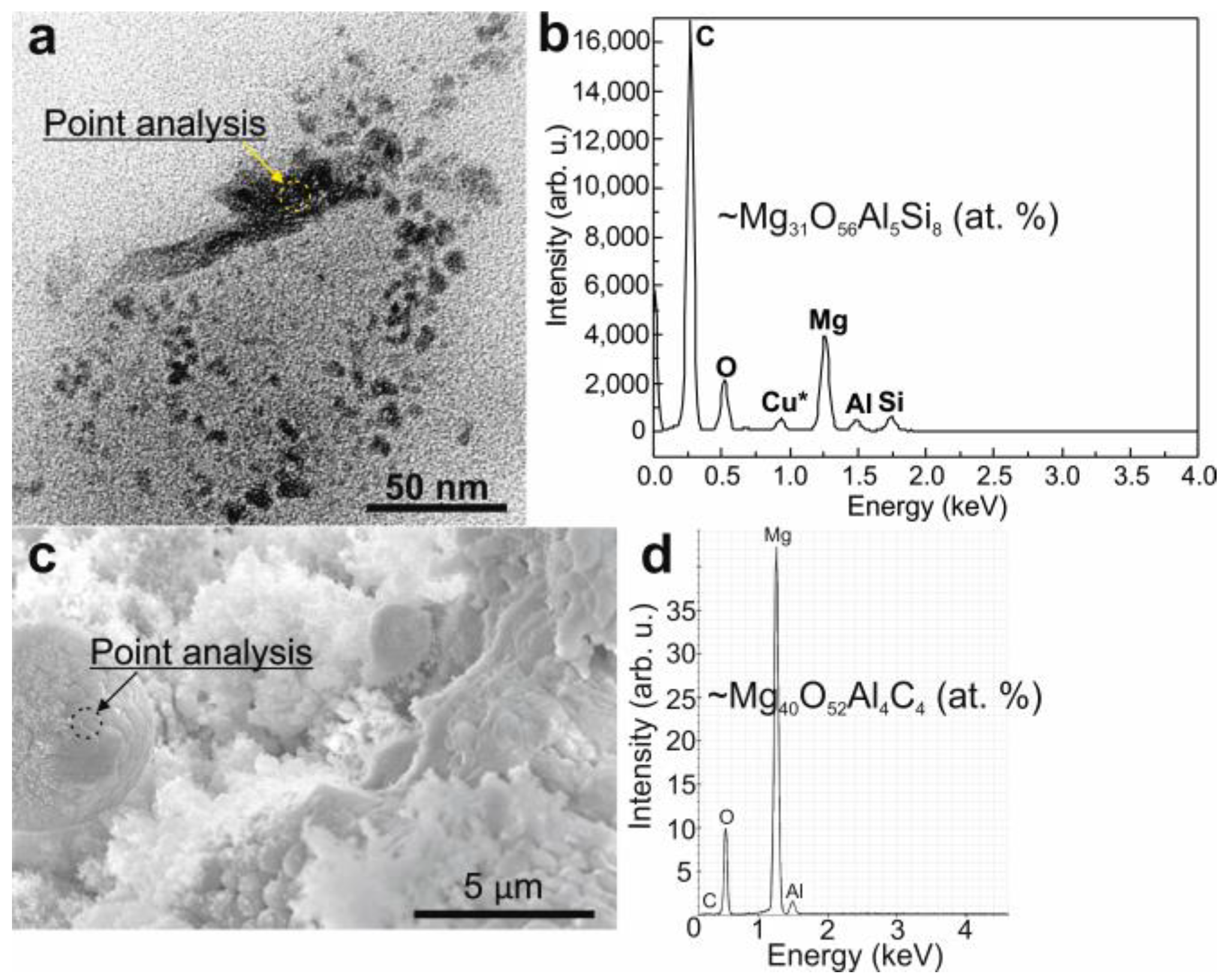
A chemical analysis was performed using the EDS point analysis performed on the individual nanoparticles in the TEM (
Figure 9a) or micrometer-sized powder mixture in the SEM (
Figure 9c). The semi-quantitative results and typical EDS spectra are shown in
Figure 9b,d. In the case of the powder collected on the glass substrate, the mean chemical composition rate of the powder was Mg
31O
56Al
5Si
8 (at. %), while the conglomerates of the powder mixture collected from the discharge chamber walls possessed a mean composition of Mg
40O
52Al
4C
4 (at. %). These results confirm the high content of oxygen preserved in the MgO particles. The detection of Al, Si, and C inside the powders may be related to the low purity of the used electrode material (AM60).
4. Discussion
The volt-second and ampere-second characteristics (waveforms) of the auxiliary and main discharges (
Figure 3) show that for the auxiliary discharge formed between the cathode “C” and the anode “Tr” (
Figure 1b,
Figure 2 and
Figure 5), the cathodic arc voltage practically does not depend on the current, while the voltage of the main discharge between the cathode “C” and the anode “A” rather weakly depends on the current of the main discharge (
Figure 3). This is a typical feature of arc discharge with a “cold” cathode, in which the plasma generation is ensured by cathode spots—extremely small formations in the immediate vicinity of the cathode surface [
26]. In the cathode spots, the conditions for almost complete ionization of the eroded cathode material are fulfilled. The mass–charge composition of the cathode spot plasma in the vacuum arc discharge with a magnesium cathode is characterized by the presence of only singly and doubly charged magnesium ions in approximately equal proportions [
34,
35]. The fundamental difference between the physical mechanisms of the operation of cathode spots of the pulsed cathodic arc under medium vacuum conditions is the formation of a film on the cathode surface. This film consists of gas molecules filling the discharge system [
36]. The formation of the film occurs in the time intervals between current pulses. When plasma is generated in cathode spots, the desorption and ionization of these molecules consumes a fraction of the energy deposited in the discharge. Since the first ionization potential of gas molecules and atoms is less than the second ionization potential of a magnesium atom (15.035 eV), e.g., 12.08 eV and 13.62 eV for O I and O
2, respectively (or close to that value, e.g., 15.75 eV for Ar I), then the appearance of gas ions in the plasma entails a decrease in the proportion of double charged Mg ions.
At atmospheric pressure, the contamination of the cathode surface with a film is obviously dramatic. Indeed, the analysis of the emission spectra of the cathodic arc plasma with magnesium electrodes at atmospheric pressure showed the presence of neutral Mg atoms as well as singly and doubly charged magnesium ions during the operation of the arc in ambient air (
Figure 4a). When the air was displaced by the gas mixture with an argon fraction of 99.9995 vol.%, the intensity of the line corresponding to doubly charged magnesium ions Mg III decreased to the noise signal level. This allows for an argument about the qualitative correspondence of the elemental compositions of the cathodic arc plasma, both at atmospheric pressure and in medium vacuum.
In this study, the argon flow rates varied from 1000 to 30,000 sccm, and the effect of argon flow rate on the characteristics of the discharges (auxiliary and main), as well as on the characteristics of the powder particles, was not revealed. This experimental fact was due to the physical nature of the elementary plasma sources, involving cathode spots, where plasma generation is concentrated on the cathode surface, where the plasma-forming medium is the cathode material and gas molecules absorbed on its surface. In turn, the concentration of argon atoms on the electrode surface mainly depends on the temperature and state of the surfaces, and to a much lesser extent on the argon flow rate.
The main result of the operation of the cathodic arc in argon at atmospheric pressure is the formation of erosion products deposited on the surfaces of electrodes and the discharge chamber (
Figure 5). To reveal the detailed qualitative and quantitative characteristics, a TEM study in combination with an electron diffraction analysis (
Figure 6 and
Figure 7), subsequent SEM investigation, and EDS analysis (
Figure 8 and
Figure 9) were performed. Thus, the morphological, structural, and elemental analyses of both individual powder particles and large agglomerates were studied. It was found that the product of electrode erosion in the cathode arc plasma at atmospheric pressure was a mixture of magnesium-containing particles of various shapes and sizes. The most characteristic types were represented by nanocubes with edge sizes of up to 40 nm and dispersed single crystals assembled into agglomerates with a characteristic size of about 100 nm. Since these particles were collected directly from the surfaces of all electrodes of the discharge assembly, currently it is impossible to unambiguously identify which of the three electrodes eroded. The results of scanning electron microscopy of individual particles deposited onto the surface of the substrates located in the vicinity of the discharge chamber walls showed that the synthesized powder mixture consisted of dendritic crystals or spherical large-sized particles. The latter may have been formed due to cooling of the liquid metal drops [
37], which were sprayed as a result of the high plasma pressure formed above the craters of the cathode. It should be noted that the formation and detachment of drops is one of the fundamental processes involved in the appearance of ectons—elementary centers of explosive electron emission [
38]. As a result of this phenomenon, self-maintenance of the cathodic arc is ensured during the duration of the discharge current pulse.
The results of the analysis of the electron diffraction patterns (
Figure 6a,d and
Figure 7a,d) and the EDS analysis (
Figure 9b,d) showed that the structure and elemental composition of the powder particles corresponded to MgO contaminated with silicon and aluminum impurities. The latter, as elements of similar atomic masses, could be contained in the initial material of the commercial Mg-based cathode. In turn, the presence of high-intensity lines corresponding to magnesium particles in the optical emission spectra of the discharge plasma, as well as a high magnesium content in the powders, demonstrated that the electrode material was of sufficient purity.
The absence of metallic Mg particles in the powder may have been due to its oxidation as a result of its interaction with oxygen directly in the discharge plasma, since the working gas was a mixture of rare argon with nitrogen, oxygen, and water vapor. According to the manufacturer, the volume fraction of oxygen in these mixtures was about 5 × 10⁻⁴ vol.%.
An important parameter—the yield of the magnesium oxide (MgO) powder—was not determined experimentally due to certain difficulties in collecting the total products of electrode erosion. However, knowing the magnesium erosion constant in the cathode spot, using Equations (1)–(3), it is possible to estimate the mass of the powder that was formed during the characteristic lifetime of the discharge system:
where
mMg is the eroded mass of the magnesium cathode; γ
Mg is 25 × 10
−9 kg/C, the magnesium erosion coefficient in the cathode spots [
39];
Id is the 120 A discharge current; τ
p is 250 × 10
−6 s, the discharge pulse duration;
fp is 10 s
−1, the discharge pulse repetition rate;
texp is 7200 s (2 h), the total time of the experiment in which the powder was produced.
After simple calculations, we can see that the eroded mass of the cathode material is
mMg ≈ 5 × 10
−5 kg. Given that the magnesium atomic mass is
MMg = 24.3 a.m.u. and 1 a.m.u. = 1.66 × 10
−27 kg, i.e.,
MMg ≈ 40 × 10
−27 kg, the number of eroded magnesium atoms can be determined using Equation (2):
where
mMg is the eroded mass of the magnesium cathode and
MMg is the magnesium atomic mass.
We suppose that each magnesium atom forms a bond with an oxygen atom, forming a MgO molecule. In this case, the mass of produced magnesium oxide can be determined using Equation (3):
where
NMg is the number of eroded magnesium atoms,
MMg is the magnesium atomic mass, and
MO = 16 a.m.u. is the oxygen atomic mass.
As a result of the estimation, a conclusion can be made that there are objective reasons why the use of the arc discharge has broad prospects for increasing the powder yield. To provide progress in this direction, according to Equation (1) there are at least three parameters that can affect an increase in productivity. The current of the main discharge can be increased by up to 10 times (up to the level of 1 kA). The duration of the main discharge pulse can be increased by 4 times (up to 1 ms) and the pulse repetition rate can be increased by 10 times (up to 100 Hz). The implementation of this approach will entail constructive changes in the discharge system producing the powder. It should also be noted that such a discharge system can be scaled, namely instead of one pair of electrodes of the main discharge, several pairs (up to 10) connected to individual arc discharge power sources can be used. The system that ensures the triggering of arc discharges will not undergo significant changes, since the use of one triggering anode will be sufficient. The discharge plasma between the conditional first pair of electrodes will trigger the subsequent ones. Taking into account possible increases in the discharge parameters and an increase in the pairs of electrodes of the discharge system by at least 10 times, the multiplicity of the increase in powder yield can be reached at a level of 10 × 4 × 10 × 10 = 4000. Therefore, the mass of magnesium oxide powder produced will be 0.16 kg/h.
In relation to increasing the resource of the discharge system of the generator, it is necessary to modernize the cathode arc initiation system. For example, it is possible to equip the triggering anode with a mechanical manipulator for its rotation and longitudinal movement. It is expected that changing the position of this electrode will help to avoid the occurrence of a short-circuiting jumper, or in case of its occurrence will make it possible to destroy it when the anode moves relative to the stationary cathode.


 ,
, 


