Article

Reinforcement of the Ceramic Matrix of CaO-ZrO2-MgO with Al2O3 Coarse Particles

Centre for Mechanical and Aerospace Science and Technologies (C-MAST), Universidade da Beira Interior, Rua Marquês d’Ávila e Bolama, 6201-001 Covilhã, Portugal
*
Author to whom correspondence should be addressed.
Ceramics 2022, 5(1), 148-160; https://doi.org/10.3390/ceramics5010013
Submission received: 17 January 2022 / Revised: 22 February 2022 / Accepted: 2 March 2022 / Published: 4 March 2022
(This article belongs to the Special Issue Advances in Ceramics)

Abstract

:
A thermal protection system is subject to high forces, in particular compression, bending and wear, to aggressive environments of high temperatures, high velocity gases and particle shock. Typically, ceramic materials appear as a first barrier or outer shield over a metallic substrate responsible for the structure. When it comes to a coating due to the small thickness, the particles of the raw material are sub-micron scale, but when a shield with a few centimeters is built its structural and economic viability requires the use of wider particle size distributions. In this work, a ceramic fine-grained matrix of CaO-ZrO2-MgO was reinforced with commercial coarse Al2O3 particles. The results show that for larger size distributions, CZM-4A, replacing 63% of fine-grained matrix by coarse Al2O3 particles, the dimensional stability is obtained (ΔL = 5%) and the good mechanical properties such as flexural strength of 154 MPa, elastic modulus of 286 GPa, and hardness of 8.5 GPa, which allows to propose this ceramic composite for a structural application.

1. Introduction

Ceramic composites are used in components subjected to extremely adverse hostile environments (high stresses, creep, wear, corrosion, impact, and very high temperatures). They are applied in thermal protection systems, among others, such as refractories linings for metal and cement industries [1,2], thermal protection system (TPS) for tiles and shields of space vehicles [3,4], thermal barrier coatings (TBC) for protection of metal substrate [5,6], and armor for ballistic impact of vehicles [7,8].
A thermal protection system (TPS) acts as an external barrier or shield over a metallic substrate responsible for the vehicle’s structure. Many times, a ceramic tile is a plate placed on the outside, glued to a metallic alloy, or advanced composites based in fiber reinforced polymers (FRP), with higher energy absorption [9,10].
The manufacture of TBC is characterized by their small thickness (up to 500 µm), and the particles of the raw materials are in a sub-micron scale. However, when a thermal shield is a plate or tile and the thickness can reach a few centimeters, its structural stability and economic viability depends on the use of wider particle size distributions up to hundreds of micras. The scale-up to promote the increase of the structural support capacity, with the consequent decrease of the shrinkage during the sintering, was carried out with the addition of coarse particles into fine-grained matrix.
Previous work has shown that CaO-ZrO2-MgO ceramic composites have good thermomechanical properties and excellent corrosion behavior [11,12]. However, their behavior in a thermodynamic system with different coarse particles deserves to be studied. This work aims to study the addition of commercial coarse alumina particles to a matrix of fine particles of CaZrO3-MgO. The MgO-Al2O3 system has a eutectic around 2000 °C. The CaO-ZrO2-MgO system has a eutectic also around 2000 °C (1982 °C). However, above 1725 °C, the solid state compatibility changes due the coexistence of different phases in equilibrium [13]. Coarse alumina particles are easily accessible and inexpensive, and their addition is intended to enable the manufacture of ceramic pieces that can be used in high temperature applications. On the other hand, it is intended to ascertain whether this matrix is stable in the presence of Al2O3 particles or whether the formation of magnesium aluminate is inevitable. Nonetheless, the addition of alumina must be balanced due to the decrease in mechanical strength because the presence of the MgAl2O4 phase.

2. Materials and Methods

Commercial (Alfa Aesar, Ward Hill, MA, USA) powders of high purity (99 wt.%) of calcium zirconate (CaZrO3), and high purity (99 wt.%) of magnesium oxide (MgO) were used as starting materials. Coarse particles of tabular alumina T60 (Al2O3 (A), Almatis, Ludwigshafen, Germany) was sieved in several classes: −500 mesh, −230 mesh, −200 + 230 mesh, and −140 + 200 mesh.
The control of the particle size after milling and sieving was done using the laser diffraction method (Beckman Coulter, LS200, Brea, CA, USA).
CaZrO3/MgO with 1:1 molar fraction (corresponding to wt.% 81.6 of CaZrO3 and 18.4 MgO) was milled in a high energy ball mill (Fritsch, Pulverisette 6, Idar-Oberstein, Germany) for 3 h using isopropyl alcohol as a media and yttria stabilize zirconia (Y-TZP, ZrO2) balls of 2 mm diameter. The mixtures were dried at 50 °C during 24 h in an oven (Carbolite, NR200-F, Sheffield, UK).
Particle size distribution (PSD) software EMMA (Available online: www.elkem.com (accessed on 23 October 2020)) was used to build continuous compositions, with the sub micra matrix of CaZrO3-MgO and alumina particles of coarse size. To promote the self-flowing properties during the powder recipes, Andreasen model with q = 0.22 was used [14]. Table 1 shows the intended composition for the PSD ceramic composites.
Plate specimens were prepared by uniaxial pressing at 50 MPa in a servo hydraulic test machine (Instron, 8800, Norwood, MA, USA), where 5 mm/min was the rate of displacement and 10s of dwell time. Pre-sintering was carried out at 1100 °C in an electrical furnace (Termolab, MLR, Águeda, Portugal) using a heating rate of 5 °C/min, dwell of 120 min. From this pre-sintering, plate bars specimens (approximate 50 mm × 6 mm × 6 mm) were cut (Struers, Accutom-2, Copenhagen, Denmark) and their surface smoothed (Struers, DAP-V, Copenhagen, Denmark) to minimize cut irregularities. Sintering at 1500 °C, with the same rate and dwell time, in the same Termolab, MLR furnace was carried out. The final dimensions of the sintered bars were evaluated in order to determine the linear shrinkage (ΔL) following the ASTM C179, Equation (1). For each material, results are the average of 10 measurements and the errors are the standard deviation.
Δ L = L s i n t L i L i × 100 ,
where ΔL (%) is the linear shrinkage in percentage, Lsint is the length after the sintering process in (mm) and Li is the initial or green length in (mm).
Bulk density and apparent porosity were measured following the ASTM C-20 standard using an analytical balance (Oertling, VA/WA, London, UK). Results are the average of 10 measurements (10 sintered bars of each material) and the errors are the standard deviations. Theoretical density values of CaZrO3, d = 4.619 g/cm3 (XRD file/card #035-0790), MgO, d = 3.57 g/cm3 (XRD file/card #071-1176), Al2O3, d = 3.987 g/cm3 (XRD file/card #46-1212), MgAl2O4, d = 3.578 g/cm3 (XRD file/card #77-1193) were used to calculate the theoretical densities (dth) of the ceramic composites, applied the rule of mixtures, Equation (2).
d t h = i = 1 n V i × d i ,
Subsequently the relative densities (dr) of all materials, Equation (3).
d r = d i d t h × 100 ,
where dth and dr are the theoretical and relative densities, respectively, di is the density of the element i, and Vi is the volume fraction of the element i, and n is the number of ingredients of the mixture.
All surfaces of prismatic bars were carefully grinding with a sequence of 400, 1000, and 2200 SiC cloths (Struers, Copenhagen, Denmark). The impulse excitation technique (IET, GrindoSonic, MK7, Leuven, Belgium) was used to experimentally determine the elastic modulus of the composites. A Poisson’s ratio of 0.25 was considered for all materials, 10 valid results was used, and the error is the standard deviation. For experimental results comparison, the upper Voigt model, Equation (4) and lower Reuss model, Equation (5) was analytically used to estimate the elastic modulus of the composites.
E c = i = 1 n V i × E i ,
1 E c = i = 1 n V i E i ,
where Ec is the elastic modulus of the composite, Ei is the elastic modulus of the phase element i, Vi is the volume fraction of the phase i, and n is the number of phases. In calculations of the analytical models of Voigt and Reuss, the values of the elastic modulus of alumina (EA = 430 GPa [6]), calcium zirconate (ECZ = 228 GPa [15]), magnesium oxide (EM = 280 GPa [15]), and magnesium aluminate, MgAl2O4 (EMA = 244.7 GPa [16]) was considered.
Flexural three bending point tests following ASTM C1161 were performed, to determine the modulus of rupture (MoR), Equation (6).
MoR = 3 × F × L 2 × w × t 2 ,
where F is the maximum or rupture load, L is the span (40 mm), w and t are the width and the thickness, respectively. Results are the average of 10 measurements of each material and the errors are the standard deviations.
For each material, three nominally identical half part of sintered bars, broken from flexural test, were embedded in epofix resin (cold-setting embedding resin kit, Struers, Copenhagen, Denmark) and their surface was diamond polished down to 1 μm through the sequence of MD cloths (Struers, RotoPol-21, Copenhagen, Denmark).
Vickers hardness were determined on the polished surfaces following the standard ASTM C-1327. Measurements were made using a Vickers hardness testing machine (Mitutoyo AVK-C2, Kawasaki, Japan) by applying 50 N for 15 s. Reported values are the average of 15 valid measurements and errors are the standard deviations.
Three half parts of each material were milled to be used for X-ray diffraction (XRD) analyses. XRD were performed using CuKα radiation (DMAX III/C, Rigaku, Japan). Data were collected between 5 and 100° (2θ) with the Bragg–Brentano (θ/2θ) horizontal geometry (flat reflection mode). The X-ray tube operated at 40 kV at 30 mA. The XRD file/card: #035-0790, for orthorhombic calcium zirconate (CaZrO3), #071-1176, for cubic magnesia (MgO), #46-1212 for rhombohedral Al2O3, #77-1193 for cubic MgAl2O4 were used to analyze the XRD diffractograms.
Microstructures were analyzed on polished and thermally etched surfaces by scanning electron microscopy (SEM, Hitachi S-3400N, Chiyoda, Tokyo, Japan) applying an accelerating voltage of 20 kV. Chemical analysis was performed using the SEM with energy dispersive X-ray probe (EDX, Brucker Quantax 400, Billerica, MA, USA). Thermal etching was carried out at 1350 °C, dwell of 30 min, with 10 °C/min heating and cooling rates. The etched surfaces, and the fracture surfaces as obtained, were coated with a thin gold layer using a turbomolecular pumped coater (Quorum Technologies, Q150T Plus, Lewes, UK).

3. Results and Discussion

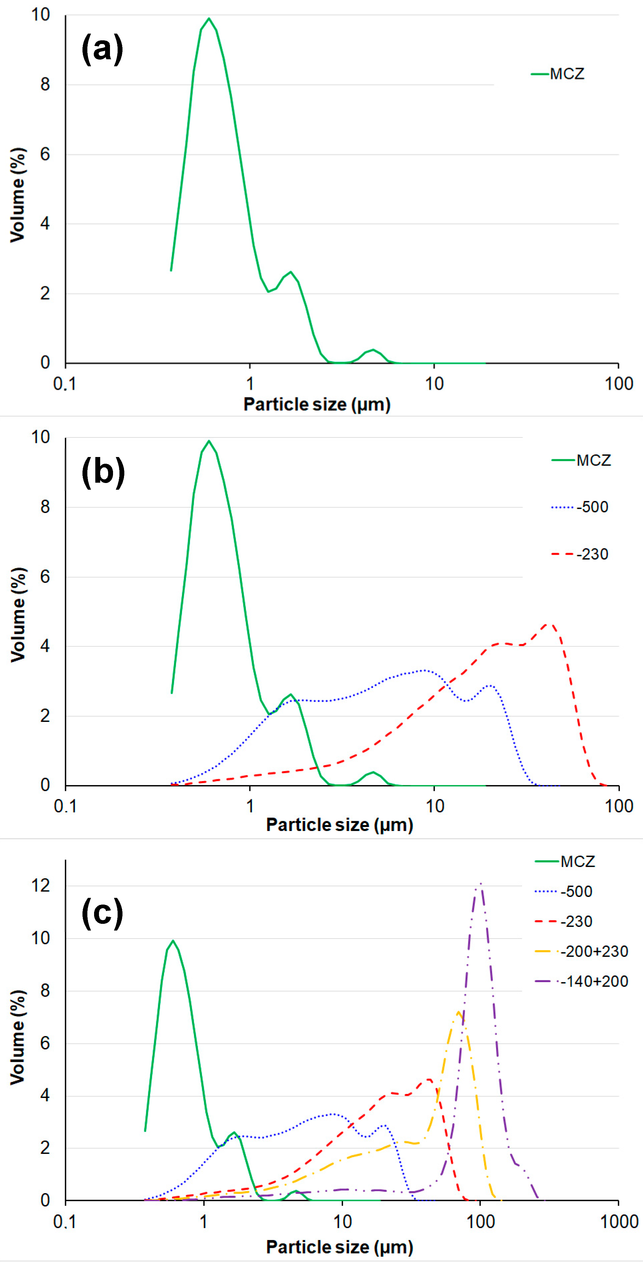
3.1. Particle Size Distribution

The particle size distribution (PSD) of the powder mixtures is presented in Figure 1. PSD of the fine particle matrix (Figure 1a), composite CZM, has a more frequent size of ~0.6 µm and 90% of its particles are smaller than 1.7 µm.
To increase the particle size of the fine-grained matrix and promote an increase in structural support, and decrease in contraction during sintering, larger alumina particles were added in order to obtain two composites, namely CZM-2A and CZM-4A. The alumina class sizes called −500 and −230 mesh combined with the fine-grained matrix class (MCZ) are the constituents of the composite CZM-2A (Figure 1b). Thus, the analysis of these three PSD classes allows us to observe that the maximum particle size is ~76 µm.
The alumina class sizes called −500 and −230 mesh combined with the fine-grained matrix class (MCZ) were added to the two alumina classes of −200 + 230 and −140 + 200 mesh, originating the composite CZM-4A (Figure 1c). Thus, the analysis of these five classes allows us to observe that the maximum particle size is ~280 µm.
In order to carry out the modelling of the CZM-2A and CZM-4A compositions, consisting of the fine-grained matrix and the coarse classes of aggregates, the PSD and powders density of class were introduced in EMMA software (Available online: www.elkem.com (accessed on 23 October 2020)), and Andreasen coefficient of 0.22 was used to promote the self-flowing properties of the powders [14,17]. The optimization is performed in order to adjust the volumetric fractions of each raw material to obtain the curve of the particle size distribution of the global experimental mixture similar to the straight line of the Andreasen model (see Figure 2). A good fit is observed between the two mixtures and the theoretical model.
With the data obtained in the EMMA software, it was exported to Table 1 the correspondent fractions of each class.

3.2. Density, Porosity and Linear Shrinkage

Table 2 shows the results obtained experimentally for apparent density and porosity. Using Equations (2) and (3), the theoretical and relative densities were determined. Composite CZM, which consists only of the fine-grained matrix, is a dense material with almost zero apparent porosity and density equal to the theoretical density.
From the analysis of Table 2, it is observed that the composite CZM-2A has high porosity (33%) and consequently a low relative density of ~59%. In this case, the existence of open porosity (33%) and closed porosity of ~8% is observed, i.e., the difference between the total apparent density (100 − 33 = 67%) and the relative density (~59%). For CZM-4A, an apparent porosity like CZM is observed, i.e., approximately zero. However, the relative density is far from the maximum (85%). Thus, it can be concluded that there is a closed porosity of ~15%.
In the manufacture of plates, it is important to assure that the linear shrinkage is reduced. A system made up of very small particles, such as the reference material, suffers, during the solid-state sintering process, a high density due to the high atomic diffusion rate. Table 3 shows the experimental results obtained for the linear shrinkage resulting of the sintering process. In this analysis, Equation (1) is applied and the dimensions of the bars in “green” were used as a reference, i.e., after the pressing stage. With the addition of the coarse particles, a gradual reduction of the linear shrinkage of the materials is verified.
From the results of Table 3, the composite CZM-4A presents less shrinkage (~5%) during its sintering, because of a wider particle size distribution and good packing of its constituent particles. In this particular composition, there are two dominant effects: the reaction between MgO and Al2O3 promotes greater densification, and a skeleton of large Al2O3 grains that stabilize the microstructure and reduce linear shrinkage. The initial particles packing of the CZM-4A composition provide a volume with lower voids; this way, a high number of contacts between the particles is promoted and a more efficient sintering is performed.

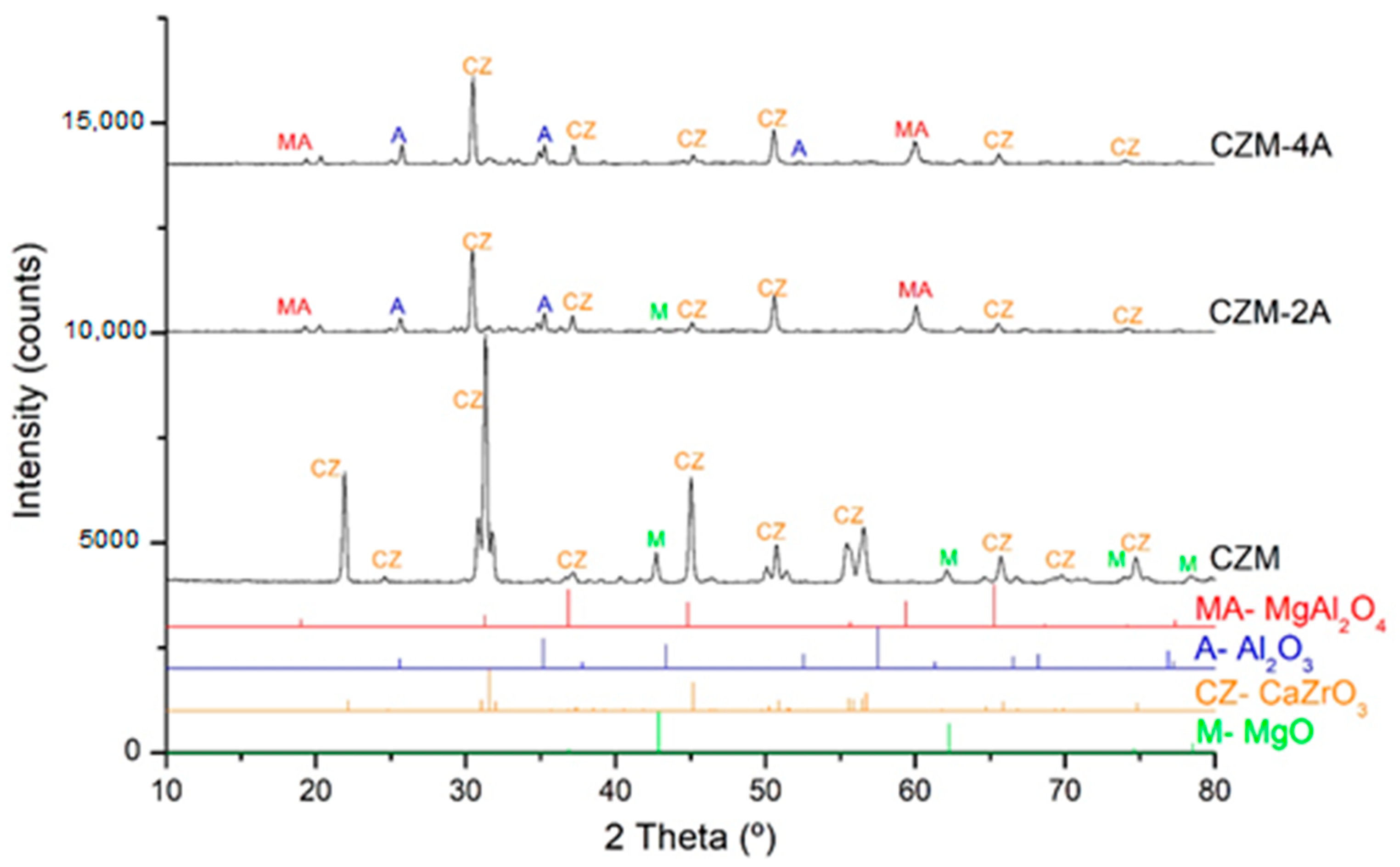
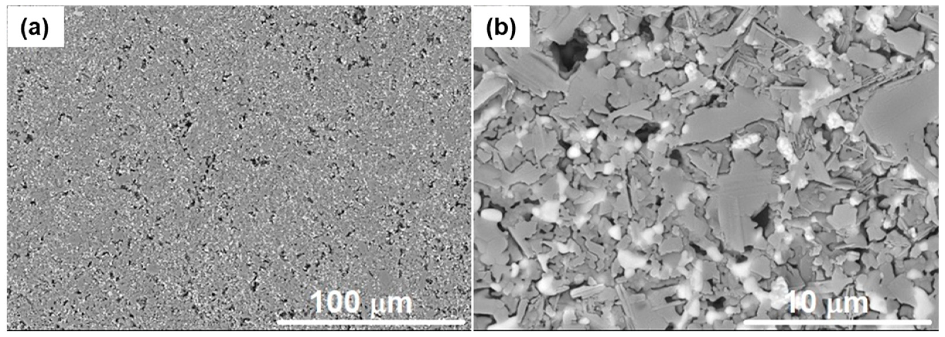
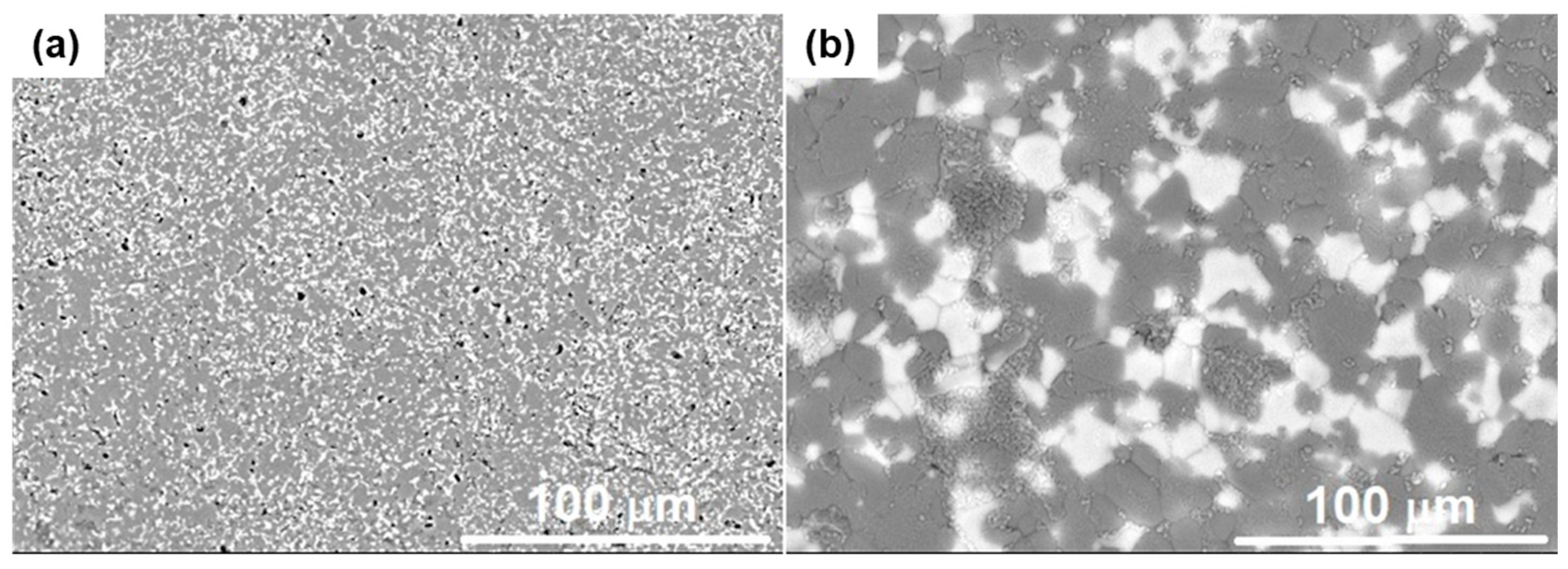
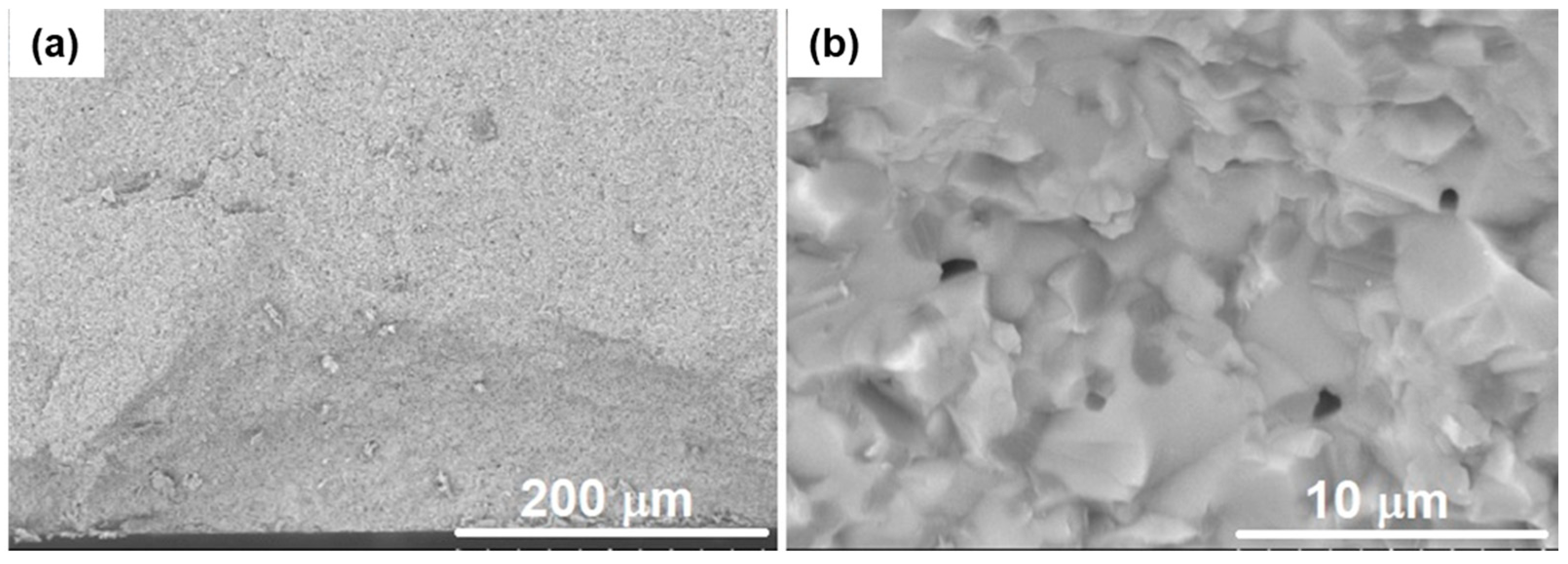
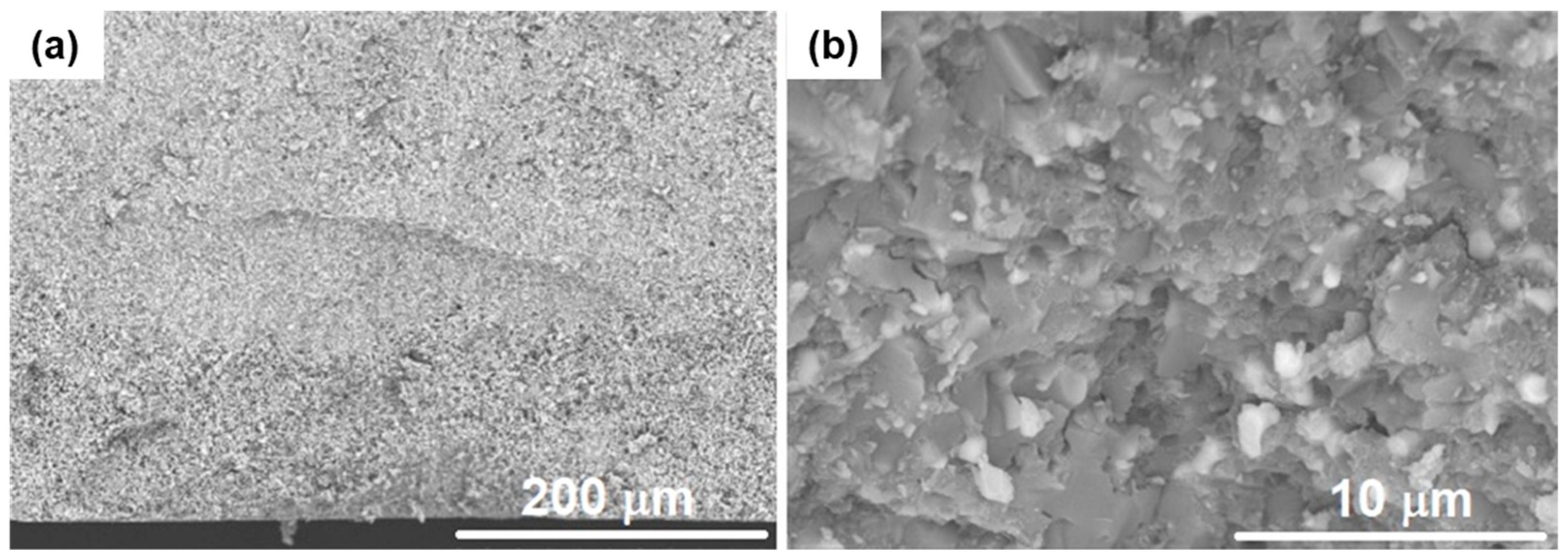
3.3. XRD and Microstructures

Figure 3 shows the experimental XRD and theoretical diffractograms of pure phases of CaZrO3 (XRD file/card #035-0790), MgO (XRD file/card #071-1176), Al2O3 (XRD file/card #46-1212), and MgAl2O4 (XRD file/card #77-1193). In order to facilitate the analysis, the main peaks were identified.
Analyzing the results of XRD, it is found that crystalline phases of calcium zirconate (CZ) is present in the three composites. The main peaks referring to magnesium oxide (MgO), at angles (2θ) of 42.9° and 62.2°, are also visible in CZM material; however, their intensity decrease is considerable for CZM-2A, and it is not visible for CZM-4A. In the CZM-2A and CZM-4A composites, the characteristic peaks of Al2O3 and MgAl2O4 are present and their intensity increases in the CZM-4A composite due to the higher alumina content in the composition. Thus, in the CZM-4A composite, MgO reacts with alumina and forms spinel.
Representative SEM micrographs of the three sintered composites are shown in Figure 4, Figure 5 and Figure 6. An image with low magnification (×500) was used to obtain an overall view of the material and an image with high magnification (×5000) was used to enable the analysis in detail of the phases and their grain boundaries. From low magnification (Figure 4a, Figure 5a and Figure 6a), homogeneous materials were observed, with an equal distribution of the reinforcement and porosity phases, which demonstrates the goodness of the manufacturing conditions.
Figure 4b shows the light gray grains of calcium zirconate (CZ) and the dark grains of MgO. CZ grains vary in size between approximately 1 and 4 µm while MgO grains are between 1 and 2 µm. This material is totally dense because no open or closed porosity is observed, which is in accordance with the results in Table 2.
From the Figure 5 analysis, corresponding to composite CZM-2A, even at low magnifications, it is possible to observe the open porosity (see also Table 2) and interconnection between the pores. The highest magnification image shows very small white grains (~1 µm) that were not detected in material 1. This is a result of the loss of MgO by calcium zirconate and its crystalline lattice becoming “purer”. Given the high porosity, it is difficult to observe the grain boundaries. However, thin dark gray lamellae with different orientations are visualized. These lamellae are typical of the crystalline phase of magnesium aluminate spinel (MgAl2O4) and are in accordance with the XRD analysis. No singular MgO grains are observed, which is justified by its reaction with alumina to forming magnesium aluminate spinel and also migration from calcium zirconate also to spinel. As a result of polishing, regions are observed where the spinel grains have suffered abrasion due to their low rigidity and good deformability.
From the composite CZM-4A (Figure 6) observation, with low magnification, it is possible to see several pores homogeneously distributed; many of them are surrounded by dense material. Compared with the microstructure of material CZM-2A, there is a clear reduction in porosity. This is consistent with the closed porosity data of Table 2. Moreover, larger white grains than those of material CZM-2A are observed. The presence of these grains is also justified by the greater purity of the CZ phase and migration of MgO to associate with Al2O3 in order to forming the spinel phase, very evident for this composite in the diffractogram of Figure 3. In addition, there are isolated grains of MgO that are not observed. At the grain boundary and in some areas agglomerated very small grains of alumina (Al2O3) and calcium zirconate (CaZrO3) phase are verified. Thus, during the consolidation process, a better particle packing of the system is promoted and the diffusion during the sintering is preferably between the fine-grained matrix particles and the periphery of the coarse particles of alumina. In this way, dimensional stability and improved mechanical strength are promoted.

3.4. Mechanical Properties

Table 4 shows the values obtained for the elasticity modulus of the three materials obtained by impulse excitation technique. In the analytical models, the values of the elastic modulus of single phases of alumina (EA = 430 GPa [6]), calcium zirconate (ECZ = 228 GPa [15]), magnesium oxide (EM = 280 GPa [15]), and magnesium aluminate, MgAl2O4 (EMA = 244.7 GPa [18]) was used. The volume fractions considered for each composite are shown in Table 1.
The values obtained for composite CZM, the reference material used as a fine particle’s matrix, with zero porosity, are slightly higher (2.5%) than the maximum value estimated by the Voigt equation. These results are within a 5% of error. In composites CZM-2A and CZM-4A, from the XRD analysis, it is clear that MgO phase reacts with alumina (Al2O3) and magnesium aluminate (MgAl2O4) was developed. Thus, the reaction occurs according to the Equation (7):
CaZrO3 + MgO + 2.Al2O3 → CaZrO3 + MgAl2O4 + Al2O3
In this way, considering a reaction, where the MgO reacts only with Al2O3, the volume fractions for the composites CZM-2A are: VCZ = 24.6%, VMgAl2O4 = 55.7% and VAl2O3 = 19.7%. For composite CZM-4A, the volume fractions are VCZ = 22.5%, VMgAl2O4 = 56.4% and VAl2O3 = 21.1%. Applying the Voigt approximation, Equation (4) and the Reuss approximation, Equation (5), approximation equations, under these conditions, the calculated values are also listed in Table 4.
The results of modulus of elasticity (Table 4) for the composite CZM-2A are influenced by porosity (relatively high apparent porosity of 33%). Since the presence of porosity in the microstructure of a ceramic will reduce considerably the modulus of elasticity.
There are several models proposed to estimate the influence of porosity. Adopting the formulation proposed by Rice [19] through Equation (8):
E = E 0 × e c P ,
where E is the modulus of elasticity (GPa), E0 is the modulus of elasticity for zero porosity (GPa), P is the apparent porosity, c is constant related to the elastic behavior of the material. For c = 2, for composite CZM-2A, the upper and lower limits for the modulus of elasticity are obtained: EVoigt = 143.2 GPa; EReuss = 135.5 GPa. Thus, the experimental value obtained (152.8 GPa) has a good approximation with the estimated range of modulus of elasticity. For the composition CZM-4A, the value of the elastic modulus is significantly higher. This fact is due to the reduced porosity of this material, and especially when compared to the CZM material; this is due to the presence of relevant fractions of alumina and MgAl2O4 that reinforce the material. Nevertheless, the modulus of elasticity obtained for composite CZM-4A, with lower porosity, is within the range of values estimated by the upper and lower approximations given by the Voigt and Reuss equations.
For the matrix (CZM), with zero porosity, an analogous hardness (7.8 GPa) with a similar composition to that of other works [15] was obtained. Composite CZM-2A has a very low hardness (1.4 GPa), which is not expected for a ceramic. This is justified by the high porosity (Table 2 and Figure 5), where the compression force carried out on the material is supported by a porous surface that deforms plastically, affected by the destruction of the pore’s cavities under the area where the pressure is applied. CZM-4A shows hardness higher than the matrix (CZM). This increase is justified by the presence of the Al2O3 and MgAl2O4 phases, both with higher hardness of 15.7 GPa [20] and 13.5 GPa [21], for commercial specimens, respectively.
Table 5 presents the experimental results obtained from the hardness and flexural resistance for the three composites.
From the flexural resistance analyses (MoR, Table 5) performed in Equation (6), the higher resistance was obtained for CZM material. CZM-2A has a great reduction in mechanical resistance justified by its high porosity. Defects play a very important role because they are points of stress concentration and micro-crack initiating points. For CZM-4A an intermediate strength of 61% of matrix MoR was obtained. This is due to the closed porosity (15%) and the modest flexural MoR of magnesium aluminate spinel phase (~140 MPa [18]). The highest variability in the results is justified by the presence of coarse particles (aggregates) that influence the growth of the cracks.
Although the addition of coarse particles introduced significant porosity (15%), the 39% reduction in mechanical strength is acceptable for numerous applications. In addition, account should be taken of the significant decrease of 63% in fine material, naturally less economical, and the considerable reduction in linear shrinkage from 24.3 to 5%.
From the bending tests, the specimens were broken into two parts. Representative fracture surfaces of each of the three materials are shown in Figure 7, Figure 8 and Figure 9.
From the fracture surfaces of the three materials, in CZM, it is observed that the fracture begins in a pore, due to the concentration of tensile stresses, and the fracture plane develops initially perpendicular to the opposite face (mode I). However, throughout the propagation, the slit rotates until it is almost parallel to the load application face. From the high magnification image, several grey CaZrO3 grains were pulled out (intergranular fracture), while the dark MgO grains are predominantly cut (transgranular fracture).
In CZM-2A, a fracture surface with greater tortuosity and porosity is noted, and the crack propagation developed along the interconnectivity between pores, due to the lower mechanical resistance. From the micrograph with larger magnification, an irregular fracture surface with interconnected pores and grains with transgranular fracture was observed. In the micrographs of CZM-4A, light grey “spots” are seen that result from the presence of aggregates in the composite composition. Debris small particles are identified along the surface. From the higher magnification, the presence of large grey colored particles and a matrix consisting of very small particles of two colors, light grey and white, was observed. A mixed fracture mode is present: large grey colored grains with transgranular fracture and empty spots illustrating pulled out small grains, corresponding to the intergranular fracture mode.
In the present work, the addition of Al2O3 is justified with the increase in mechanical strength but taking care not to increase the porosity. This way, a balance with Al2O3 and AlMg2O4 phase crystalline is needed, because the “pure” Al2O3 phase should be sufficient to balance the decrease in mechanical strength due to the presence of the MgAl2O4 phase.

4. Conclusions

In this work, the reinforcement of a matrix of calcium zirconate and magnesium oxide (CZM, CaZrO3-MgO) with coarse particles of alumina was studied in order to increase the particle size scale of the material. The availability and superior alumina properties justify its use. However, the reaction between Al2O3 and MgO phases promotes the formation of the magnesium aluminate spinel phase (MgAl2O4), resulting in a composite with potentially inferior properties. Under the same conditions of processing, grinding, pressing, and sintering, three comparable materials were obtained. The two scaled composites (CZM-2A, CZM-4A) were designed with a self-flowability particle packaging model of Andreasen (q = 0.22).
As expected in CZM-2A, a large part of magnesia (MgO) reacts with alumina leading to magnesium aluminate spinel (55.7%) formation, while 19.7% remains as Al2O3 phase. In addition, a material with high porosity (~33%) is generated. In CZM-4A, due to the lower amount of matrix and higher content of alumina aggregates, the magnesium aluminate spinel is also reached (56.4%) and the Al2O3 phase increases to 22.5%. This composite has almost zero open porosity and only closed porosity is observed.
The elastic modulus is in line with expectations, with the reduction being quite marked for CZM-2A composite from 256 GPa (matrix) to 153 GPa, justified by the presence of the magnesium aluminate spinel phase and its high porosity. Although CZM-4A composite has a lower MoR (~154 MPa), it has greater hardness (increase from 7.6 to 8.5 GPa) and higher elastic modulus (~286 GPa).
In this context, the properties studied, associated with their superior dimensional stability (ΔL = 5%), and the considerable decrease of 63% in low size ingredients (CaZrO3-MgO), with less than 2 µm, by commercial coarse raw alumina (up to 280 µm), demonstrates the viability of the CZM-4A material for structural applications, because it is possible to obtain low porosity and the “pure” Al2O3 phase should be sufficient to balance the decrease in mechanical strength due to the presence of the MgAl2O4 phase.

Author Contributions

Conceptualization, A.P.S.; methodology, A.P.S.; software, A.M. and D.F.M.; validation, A.M., D.F.M. and A.P.S.; formal analysis, A.P.S.; investigation, J.M. and D.F.M.; writing—original draft preparation, J.M.; writing—review and editing, A.P.S. All authors have read and agreed to the published version of the manuscript.

Funding

This work was supported by: -Center (CENTRO 2020) and the European Union through the European Regional Development Fund (ERDF), Centro-01-0145-FEDER-000017-EMaDeS-Energy; -Portuguese Foundation for Science and Technology, I.P., FCT/MCTES, through national funds (PIDDAC), under the R&D Unit C-MAST/ Center for Mechanical and Aerospace Science and Technologies, reference: Project UIDB/00151/2020.

Institutional Review Board Statement

Not applicable.

Informed Consent Statement

Not applicable.

Data Availability Statement

Not applicable.

Acknowledgments

This work was supported by the following projects and organisms: Portugal: Centro-01-0145-FEDER-000017-EMaDeS-Energy, Materials and Sustainable Development, co-financed by the Portugal 2020 Program (PT 2020), within the Regional Operational Program of the Center (CENTRO 2020) and the European Union through the European Regional Development Fund (ERDF); Portuguese Foundation for Science and Technology, I.P. FCT/MCTES through national funds (PIDDAC), under the R&D Unit C-MAST/ Center for Mechanical and Aerospace Science and Technologies, reference: Project UIDB/00151/2020.

Conflicts of Interest

The authors declare no conflict of interest.

References

  1. Braulio, M.A.L.; Rigaud, M.; Buhr, A.; Parr, C.; Pandolfelli, V.C. Spinel-containing alumina-based refractory castables. Ceram. Int. 2011, 37, 1705–1724. [Google Scholar] [CrossRef]
  2. Pinto, D.G.; Silva, A.P.; Segadães, A.M.; Devezas, T.C. Thermomechanical evaluation of self-flowing refractory castables with and without the addition of aluminate cement. Ceram. Int. 2012, 38, 3483–3488. [Google Scholar] [CrossRef]
  3. Uyanna, O.; Najafi, H. Thermal protection systems for space vehicles: A review on technology development, current challenges and future prospects. Acta Astronaut. 2020, 176, 341–356. [Google Scholar] [CrossRef]
  4. May, M.; Rupakula, G.P.; Matura, P. Non-polymer-matrix composite materials for space applications. Compos. Part C Open Access 2020, 3, 100057. [Google Scholar] [CrossRef]
  5. Clarke, D.R.; Phillpot, S.R. Thermal barrier coating materials. Mater. Today 2005, 8, 22–29. [Google Scholar] [CrossRef]
  6. Cao, X.Q.; Vassen, R.; Stoever, D. Ceramic materials for thermal barrier coatings. J. Eur. Ceram. Soc. 2004, 24, 1–10. [Google Scholar] [CrossRef]
  7. Appleby-Thomas, G.J.; Jaansalu, K.; Hameed, A.; Painter, J.; Shackel, J.; Rowley, J. A comparison of the ballistic behaviour of conventionally sintered and additively manufactured alumina. Def. Technol. 2020, 16, 275–282. [Google Scholar] [CrossRef]
  8. Dresch, A.B.; Venturini, J.; Arcaro, S.; Montedo, O.R.K.; Bergmann, C.P. Ballistic ceramics and analysis of their mechanical properties for armour applications: A review. Ceram. Int. Part A 2021, 47, 8743–8761. [Google Scholar] [CrossRef]
  9. Triantou, K.; Perez, B.; Marinou, A.; Florez, S.; Mergia, K.; Vekinis, G.; Barcena, J.; Rotarmel, W.; Zuber, C.; de Montbrun, A. Performance of cork and ceramic matrix composite joints for re-entry thermal protection structures. Compos. Part B-Eng. 2017, 108, 270–278. [Google Scholar] [CrossRef]
  10. Wanga, Z.; Lia, Z.; Xionga, W. Experimental investigation on bending behavior of honeycomb sandwich panel with ceramic tile face-sheet. Compos. Part B-Eng. 2019, 164, 280–286. [Google Scholar] [CrossRef]
  11. Serena, S.; Sainz, M.A.; Caballero, A. The system Clinker–MgO–CaZrO3 and its application to the corrosion behavior of CaZrO3/MgO refractory matrix by clinker. J. Eur. Ceram. Soc. 2009, 29, 2199–2209. [Google Scholar] [CrossRef]
  12. Silva, A.; Booth, F.; Garrido, L.; Aglietti, E.; Pena, P.; Baudín, C. Sliding wear of CaZrO3-MgO composites against ZrO2 and steel. J. Eur. Ceram. Soc. 2017, 37, 297–303. [Google Scholar] [CrossRef]
  13. De Aza, A.H.; Iglesias, J.E.; Pena, P.; De Aza, S. Ternary System Al2O3–MgO–CaO: Part II, Phase Relationships in the subsystem Al2O3–MgAl2O4–CaAl4O7. J. Am. Ceram. Soc. 2000, 83, 919–927. [Google Scholar] [CrossRef]
  14. Silva, A.P.; Segadães, A.M.; Pinto, D.G.; Oliveira, L.O.; Devezas, T.C. Effect of particle size distribution and calcium aluminate cement on the rheological behaviour of all-alumina refractory castables. Powder Technol. 2012, 226, 107–113. [Google Scholar] [CrossRef]
  15. Silva, A.P.; Booth, F.; Garrido, L.; Aglietti, E.; Pena, P.; Baudín, C. Young’s modulus and hardness of multiphase CaZrO3-MgO by micro and nanoindentation. J. Eur. Ceram. Soc. 2018, 38, 2194–2201. [Google Scholar] [CrossRef]
  16. Gaillac, R.; Pullumbi, P.; Coudert, F.X. ELATE: An open-source online application for analysis and visualization of elastic tensors. J. Phys. Condens. Matter 2016, 28, 275201. [Google Scholar] [CrossRef] [PubMed]
  17. Pileggi, R.G.; Studart, A.R.; Innocentini, M.D.M.; Pandolfelli, V.C. High-performance refractory castables. Am. Ceram. Soc. Bull. 2002, 81, 37–42. [Google Scholar]
  18. Mohan, S.K. Densification and Characterization of Magnesium Aluminate Spinel from Commercial Grade Reactants: Effect of Milling and Additives. Master’s Thesis, Technology in Ceramic Engineering, National Institute of Technology, Rourkela, India, 2016. [Google Scholar]
  19. Rice, R.W. Porosity of Ceramics; Marcel Dekker, Inc.: New York, NY, USA, 1998; p. 102. [Google Scholar]
  20. Technical Support for Advanced Alumina Ceramic: Aluminon 995; International Syalons (Newcastle) Limited: Newcastle, UK. Available online: https://www.syalons.com (accessed on 8 January 2021).
  21. Shi, Z.; Zhao, Q.; Guo, B.; Ji, T.; Wang, H. A review on processing polycrystalline magnesium aluminate spinel (MgAl2O4): Sintering techniques, material properties and machinability. Mater. Des. 2020, 193, 108858. [Google Scholar] [CrossRef]
Figure 1. PSD of the ingredient’s classes used in the three composites. (a) CZM; (b) CZM-2A: CZM and alumina classes of −500 and −230 mesh; (c) CZM-4A: CZM and alumina classes of −500, −230, −200 + 230 and −140 + 200 mesh.
Ceramics 05 00013 g001
Figure 2. Graphical illustration of the PSD optimization according Andreasen coefficient of 0.22. (a) Composition of the CZM-2A (mixture 2); (b) Composition of the CZM-4A (mixture 3).
Ceramics 05 00013 g002
Figure 3. XRD analysis of the three composites: CZM, CZM-2A, and CZM-4A. Theoretical diffractograms of pure phases of CaZrO3 (XRD file/card #035-0790), MgO (XRD file/card #071-1176), Al2O3 (XRD file/card #46-1212), and MgAl2O4 (XRD file/card #77-1193) were represented. The main peaks identified were: CZ (CaZrO3), M (MgO), A (Al2O3), and MA (MgAl2O4).
Ceramics 05 00013 g003
Figure 4. Microstructural features of the CZM material. SEM of polished surfaces at low magnification (a), and thermally etched surface at high magnification (b). Dark grains: MgO. Small and medium gray faceted grains: CaZrO3.
Ceramics 05 00013 g004
Figure 5. Microstructural features of the CZM-2A composite. SEM of polished surfaces at low magnification (a), and thermally etched surface at high magnification (b). Large pores of irregular shape are observed. White small grains: CaZrO3. Gray larger grains: Al2O3. Thin elongated lamellae: MgAl2O4.
Ceramics 05 00013 g005
Figure 6. Microstructural features of the CZM-4A composite. SEM of polished surfaces at low magnification (a), and thermally etched surface at high magnification (b). White small grains: CaZrO3. Very small and medium light gray grains: Al2O3. Larger dark grains: MgAl2O4.
Ceramics 05 00013 g006
Figure 7. Characteristic fracture surface of the CZM material at (a) low magnification (250×), and (b) high magnification (5000×).
Ceramics 05 00013 g007
Figure 8. Characteristic fracture surface of the CZM-2A composite at (a) low magnification (250×), and (b) high magnification (5000×).
Ceramics 05 00013 g008
Figure 9. Characteristic fracture surface of the CZM-4A composite at (a) low magnification (250×), and (b) high magnification (5000×).
Ceramics 05 00013 g009
Table 1. Composition of the three composites.
MaterialIngredientsSize Classes (mesh)Mass Fraction (wt.%)Volume Fraction (vol.%)
CZMMgO 18.422.5
CaZrO3 81.677.5
CZM-2AMgO 8.610.0
CaZrO3 38.434.6
Al2O3−50020.055.4
−23033.0
CZM-4AMgO 7.38.5
CaZrO3 32.729.2
Al2O3−50015.062.3
−23015.0
−200 + 23015.0
−140 + 20015.0
Table 2. Apparent porosity and densities of the three materials.
MaterialApparent Porosity
P (%)
Apparent Density
d (g/cm3)
Theoretical Density
dt (g/cm3)
Relative Density
dr (%)
CZM0.03 ± 0.14.38 ± 0.14.38100
CZM-2A33.3 ± 0.52.44 ± 0.14.1658.7
CZM-4A0.09 ± 0.13.52 ± 0.14.1485.0
Table 3. Linear shrinkage of the composites.
MaterialLinear Shrinkage (%)
CZM24.3 ± 0.3
CZM-2A15.7 ± 0.1
CZM-4A5.0 ± 0.1
Table 4. Elastic modulus of the composites.
MaterialEexp (GPa)EVoigt (GPa)EReuss (GPa)
CZM245.7 ± 3.1239.7237.9
CZM-2A152.8 ± 3.2277.1262.2
CZM-4A286.4 ± 15.2282.9266.4
Table 5. Hardness (H) and modulus of rupture (MoR) of the composites.
MaterialH (GPa)MoR (MPa)
CZM7.8 ± 0.1251.4 ± 2.9
CZM-2A1.4 ± 0.270.1 ± 3.9
CZM-4A8.5 ± 0.1154.0 ± 10.0
Publisher’s Note: MDPI stays neutral with regard to jurisdictional claims in published maps and institutional affiliations.

