1. Introduction
Currently, with the evolution of technology and the growing need of miniaturization, the interest in developing micro-fabrication methods for different materials has been growing. Among these materials are ceramics and glass, due to their unique properties such as high temperature and chemical resistance as well as their biocompatibility. Glass is also the material of choice when it comes to optical applications. While there exist different methods to machine glass on the micro-scale, including thermal, mechanical, and chemical methods, such methods have limitations, including the achieved surface quality, machining speed, setup affordability and complexity. Spark Assisted Chemical Engraving (SACE) is a relatively new nonconventional machining technology for non-conductive materials, mainly glass.
In SACE, the work-piece and two electrodes are dipped in an alkaline solution. Upon applying a voltage between the tool and counter-electrode, bubbles form in the tool vicinity and they coalesce into a gas film that isolates the tool tip from the surrounding electrolyte. The current passes through the tool tip in the form of high energy electrical discharges. These discharges lead to high local temperature in the tool’s vicinity reaching 500–600 °C. This was quantified by using thermocouples [
1], by performing spectroscopic measurements [
2], and based on estimating the glass viscosity in the machining zone [
3]. Later, a heat transfer model was developed to estimate this temperature [
4]. The heat source from the tool was considered to be located on the glass surface. By matching the evolution of the simulated temperature gradient with the size of machined structures (holes), the temperature needed to machine glass by SACE was estimated to be around 600 °C.
The major SACE machining modes are gravity-feed and constant velocity-feed. In gravity-feed drilling, the tool is made to push into the substrate under the action of its weight. Hence, machining proceeds under the action of a constant force. In constant velocity-feed, the tool is moved downwards towards the substrate at a constant feed-rate during machining. Each of the two methods has its advantages and limitations. In gravity-feed the material removal rate is high (reaches around 100 µm/s) for depths up to about 200–300 µm and is significantly reduced to a few micrometers per second for higher depths where heat affected zones form [
5]. In gravity-feed machining, the tool, or heat source, is always in contact with the substrate which accelerates machining for shallow depths (around 100 microns). However, drilling slows down for higher depths as electrolyte cannot be flushed into the machining zone. Constant velocity-feed drilling has the advantage of less frequent contact between the tool and glass surface but is limited by the range of allowable tool feed-rates and is normally applied up to around 300 µm depth. In fact, for this machining mode drilling progress is determined by the etching rate relative to tool speed. If the etching rate is higher than tool speed a tool–substrate gap forms allowing flushing, otherwise this mode will be similar to gravity-feed. When a gap exists, machining can either progress for moderate gap size or slow down for high gaps. Studies showed that for a gap higher than 20 µm the heat source will be far from the surface, hence limiting machining [
6].
Attempts have been made to enhance machining rate and quality. These include modifying the tool shape, including using flat sidewall–flat front tool [
7], side-insulated tool [
8], drill bit [
9], helical tool with high-speed rotation [
10], internally structured tube electrode [
11] and spherical tip tool [
12]. Other attempts include using pulsed voltage [
13,
14], modifying the electrolyte constituents [
15,
16], adding tool motion such as rotation [
17] and orbital motion [
18], adding tool vibration [
19], vibrating electrolyte [
20] and doing magnetic assisted field machining [
21,
22]. It was also shown that deeper holes could be established through adding pressurized electrolyte flow [
23] and by applying counter-resistant feeding through reducing the magnitude of contact force between the tool and substrate as drilling progresses [
24]. Furthermore, basic algorithms based mainly on the tool–substrate contact force were applied to enhance machining rate and increase the structure aspect ratio, such as adjusting the machining voltage upon detecting a force signal [
25]. While these approaches generally enhanced machining rate, depth or quality for specific machining conditions, there is no study that quantifies trends in terms of the effect of each of the machining limiting factors, i.e., heating and flushing, on the machining progress. In this paper, we study and present such trends. The effect of heating and flushing on machining progress is evaluated by considering the recorded reduction in drilling time for holes deeper than 100 microns. This work serves to enhance the understanding of the importance and precedence of heating and flushing in terms of each one’s effect on machining progress. We believe that this work enhances the fundamental knowledge about the SACE machining process, hence allowing enhancement of SACE machining capabilities.
2. Experimental Setup
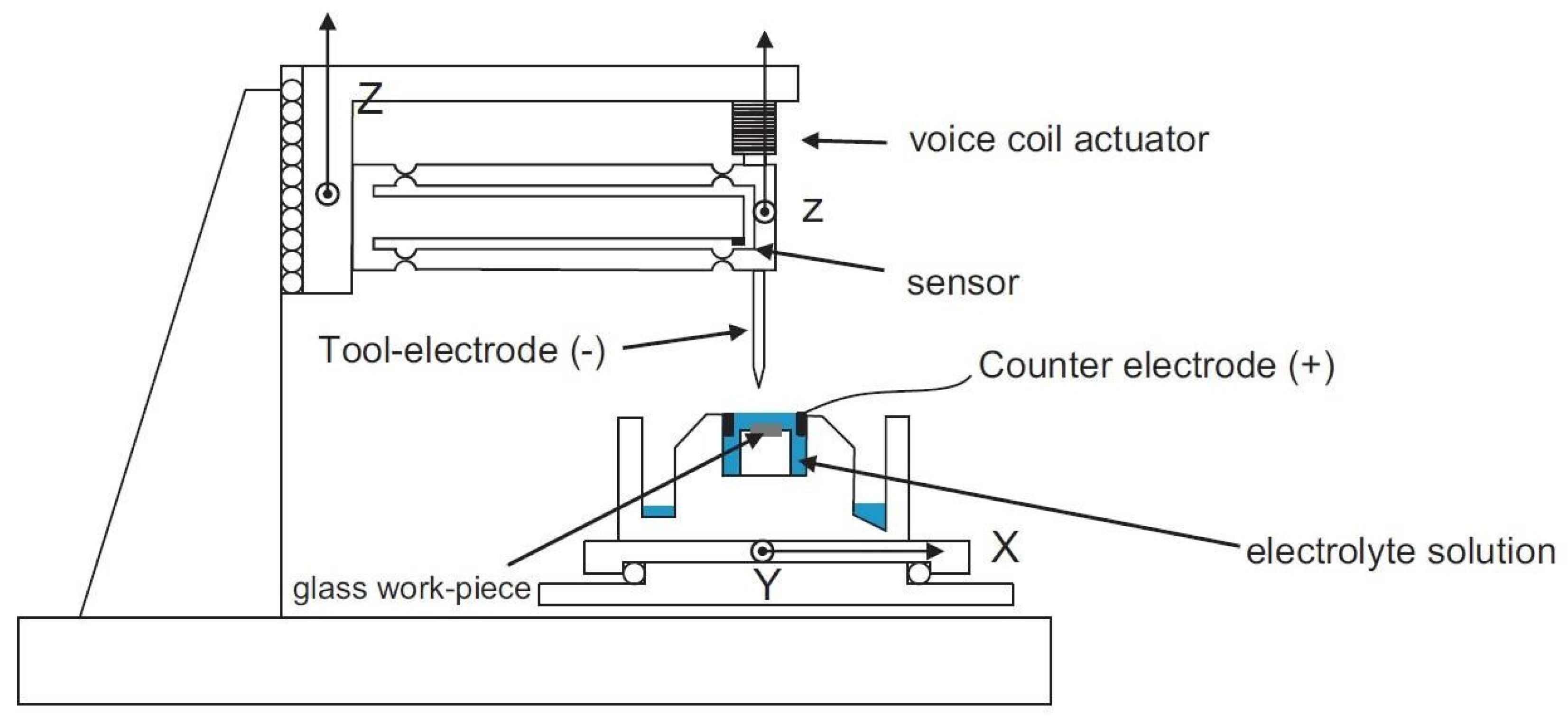
The machining setup is composed of a machining head which holds the tool and that is guided in the Z-direction by a linear precision stage with 1 µm resolution (
Figure 1). The head, composed of a flexible structure, contains a voice coil actuator that can move the structure in both upwards and downwards Z-directions. It also has a spindle that allows tool rotation (up to 3000 rpm). The head can be operated in the force sensor mode, where machining forces acting on the tool (in the upward direction) are measured by the force controller which exerts an opposite force on the structure to keep it at the same initial position. The force sensor can measure forces in the range of 0 to 5 N (signal noise is around 10 mN rms).
The processing cell, mounted on an XY stage, contains the glass work-piece where it allows aligning it with the tool. All electrolytic solutions, Sodium hydroxide (NaOH) and Potassium hydroxide (KOH) of different concentrations, were prepared with deionized water. The liquid level above the work-piece was controlled passively to be 1 mm with an overflow system, where the electrolyte losses were compensated using a micro-pump. The work-pieces were microscope glass slides (Bio Nuclear Diagnostics Inc., Toronto, ON, Canada) and cylindrical, 250 µm diameter, stainless steel tools were used.
3. Results and Discussion
From SACE gravity-feed drilling it is known that insufficient flushing of the machining zone is responsible for the reduced material removal rate at depths higher than 200 µm. On the other hand, adequate local glass heating through glass-tool contact is also important for drilling to proceed well. To observe this trade-off in terms of prevalence and significance of heating and/or flushing on machining progress, some tool motion feedback algorithms were applied. The feedback signal used was the tool–substrate contact force (also called machining force). The trends were identified through measuring and comparing the drilling time for each case.
3.1. Enhancing Surface Heating by Prolonged Tool–Surface Contact
The first algorithm aims to stop the tool motion when a given force threshold is exceeded until the force goes back to zero (as the surface below the tool is progressively machined). For this algorithm stopping the tool motion is referred to as a counter-action. The aim of the current algorithm is to see the effect of heating on the machining progress. Therefore, a low-viscosity electrolyte (50 wt% KOH) was chosen where flushing is less of an issue. Note that increasing the force threshold at which the counter-action takes place results in making longer contact between the substrate and the heat source, the tool, and is expected to enhance local heat transfer. The holes drilled were 400 µm deep while the machining voltage was 30 V, just above the critical voltage required to form the gas film.
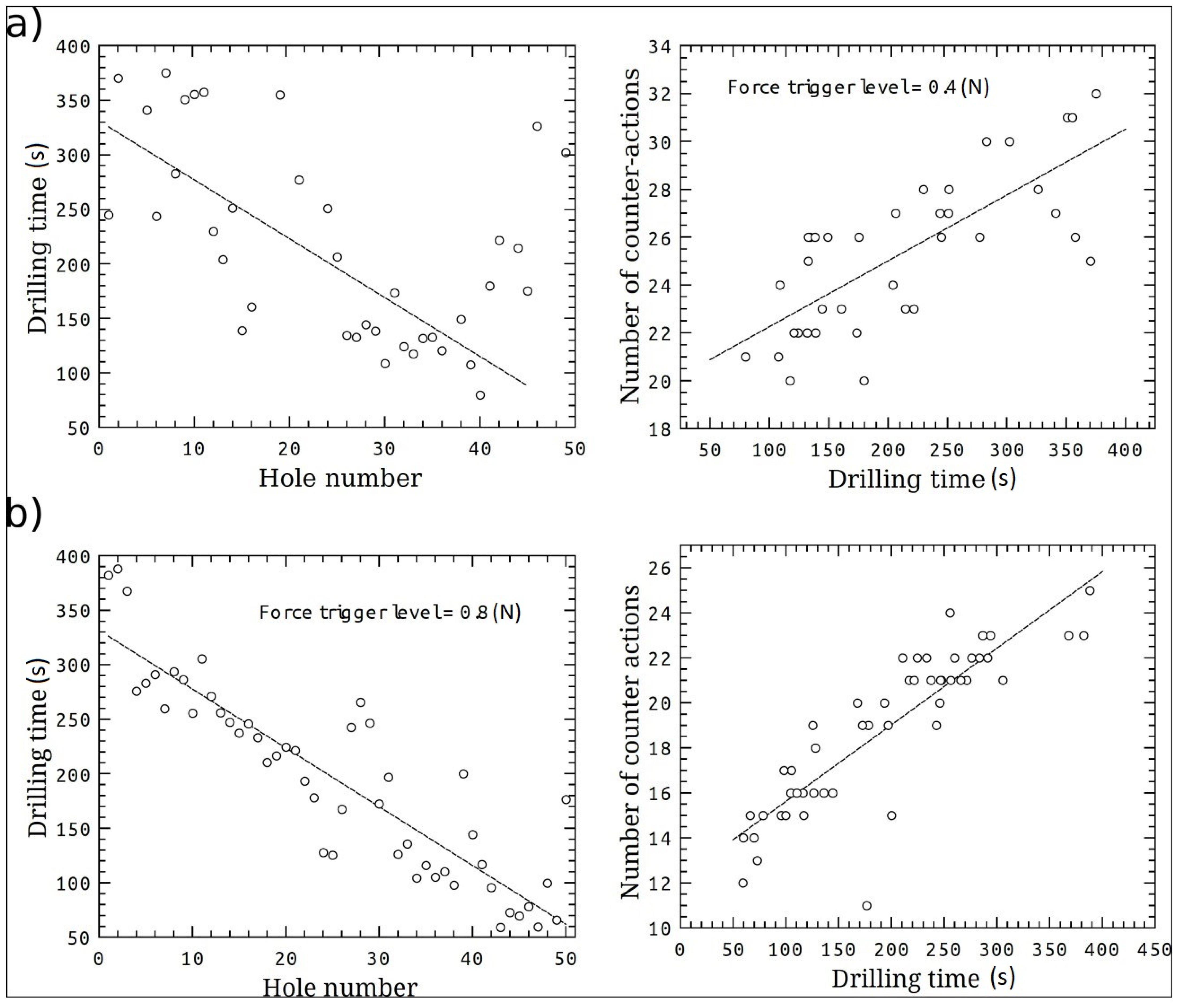
Figure 2 shows the results.
Figure 2a shows the drilling time versus the hole number as well as the number of counter-actions (upward movements) taken when the contact force exceeds a threshold of 0.4 N.
Figure 2b shows similar information where in this case the force threshold level is 0.8 N. The effect of surface heating on accelerating the drilling process is witnessed by the decrease in drilling time between holes as drilling progresses and this is shown in both
Figure 2a,b. Comparison of drilling times for different force thresholds (trigger levels) further supports this statement. As depicted in
Figure 2, similar drilling time range (50 to around 400 s) resulted when using low force threshold of 0.4 N (
Figure 2a) and high threshold of 0.8 N (
Figure 2b). However, the number of counter-actions differed. In fact, the average number of counter-actions is lower for the higher force threshold due to the more efficient work-piece heating.
3.2. Enhancing Flushing While Maintaining Heating through Creating a Machining Gap
Based on these findings, ways to enhance the flushing while maintaining the local heat were investigated. The experiments were performed in 30 wt% NaOH while applying 30 V for 250 µm deep holes. To ensure frequent occurrence of contact forces (tool–substrate contact), the tool was fed at 50 µm/s based on the findings in [
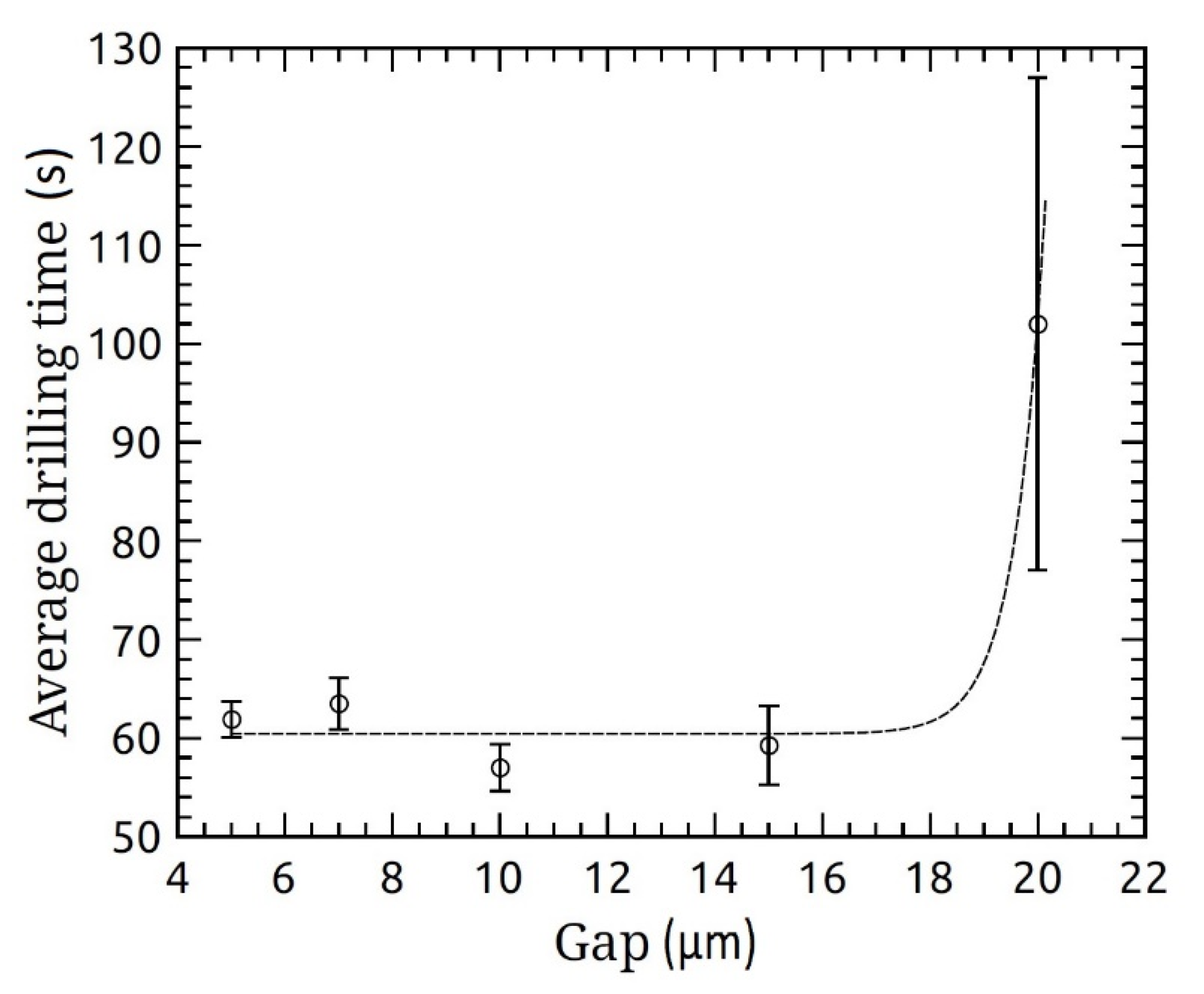
26]. This speed ensures tool–glass contact while machining for the applied machining conditions. For promoting flushing, the tool was moved upwards whenever a force exceeding a low threshold of 0.4 N was detected until the force became null, meaning that the tool was on the substrate surface. This step was followed by an upward tool motion, which is called “gap” in this text as it refers to the vertical distance created between the tool and the machined glass surface. Therefore, the counter-action for this algorithm is moving the tool upwards upon exceeding the force threshold until the force is null and then creating a machining gap between the tool and the substrate. The investigated gap ranged from 5 to 20 µm.
While results show that the drilling time remains the same when creating gaps up to 15 µm (
Figure 3), it increased dramatically for a 20 µm gap. Furthermore, for every set of successively drilled holes, drilling time decreased as more holes were drilled. This transient is attributed to the heating of the electrolyte and work-piece over time. Note that while reduced drilling time was expected when creating higher gaps due to flushing the hole, the drilling time was indifferent for gaps ranging from 5 to 15 µm. Therefore, the present results show that the strategy of creating a tool–surface gap when the force threshold is exceeded does not efficiently contribute to local flushing.
A possible explanation is that the moving away from the surface does not promote local flow for the used electrolyte due to its high viscosity (12.6 cP at room temperature). This strategy becomes even more counter-productive for large gaps (higher than 15 µm) as the local heat is dissipated when the tool is away from the glass surface, thus the machining zone is no longer heated efficiently.
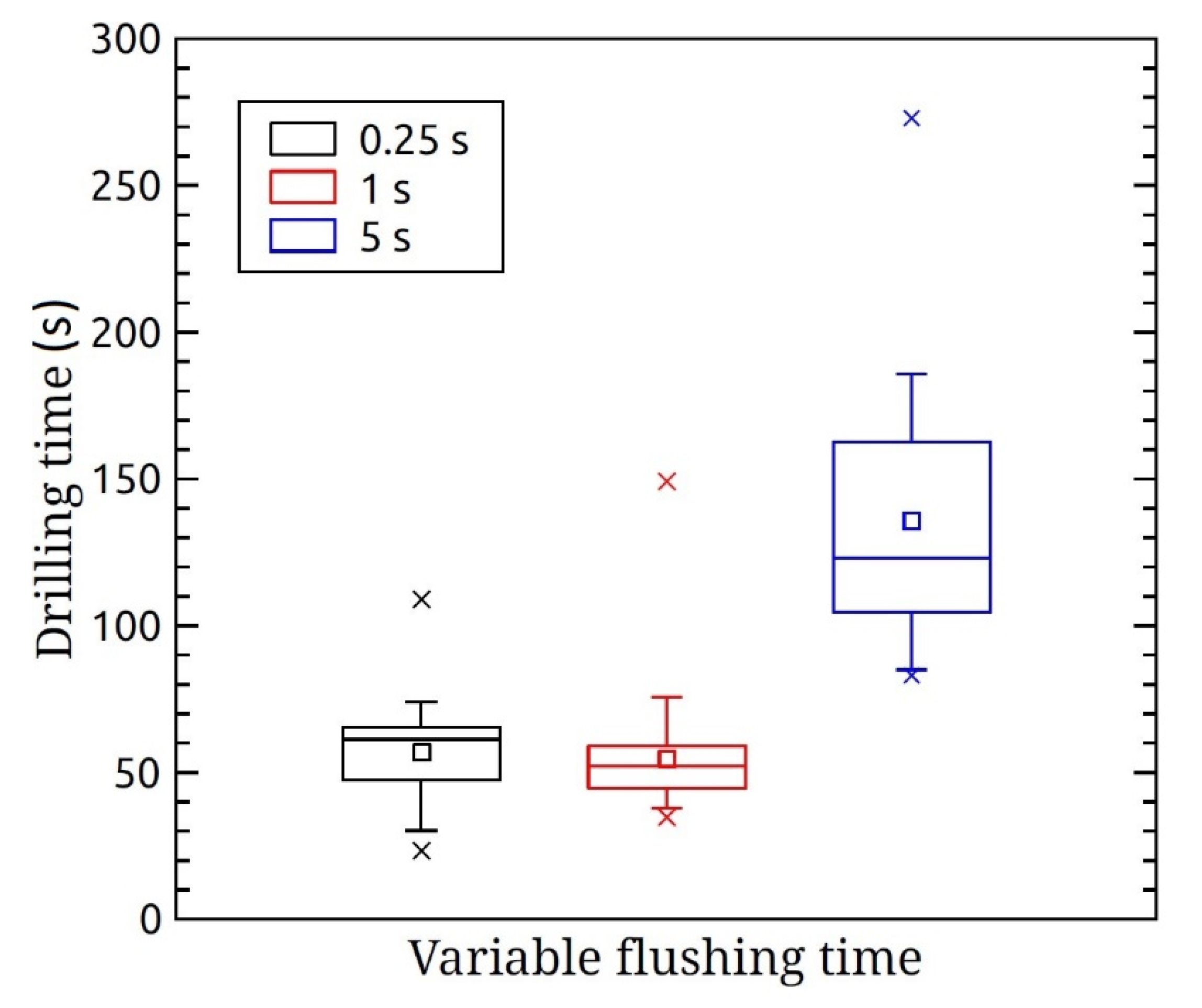
3.3. Enhancing the Flushing in the Machining Gap by a Delayed Tool Motion
Based on the discussed results, the next step was checking whether adding a waiting time once a gap is created can enhance flushing. The previous algorithm was modified by adding a waiting time (called flushing time) once a 10 µm gap was established, before proceeding further with drilling. The chosen gap was 10 µm based on the results shown in
Section 3.2. The gap was created between the tool and hole surface once a specific force threshold was exceeded as explained in
Section 3.2. Therefore, for this algorithm the counter-action refers to moving the tool upwards upon exceeding a force threshold of 0.4 N until the force becomes null and then creating a 10 µm tool–substrate gap. Afterwards, a certain waiting time, called flushing time, is added to allow electrolyte to flow into the hole before proceeding with machining. The flushing time ranged between 0.25 and 5 s while the same machining conditions (30 V, 50 μm/s, 30 wt% NaOH using 50 μm/s) were used as with the previous experiments. Similar drilling time was observed for flushing time up to 1 s (
Figure 4). However, the total number of counter-actions decreased in this case, implying that the frequency of force occurrence is lower. The present results indicate that flushing can be enhanced when allowing more time to evacuate the machining zone (after establishing the gap). However, a flushing time longer than 5 s can significantly increase the drilling time due to heat loss, as shown on
Figure 4.
3.4. Enhancing the Flushing While Maintaining Heating by Applying Tool Vibrations
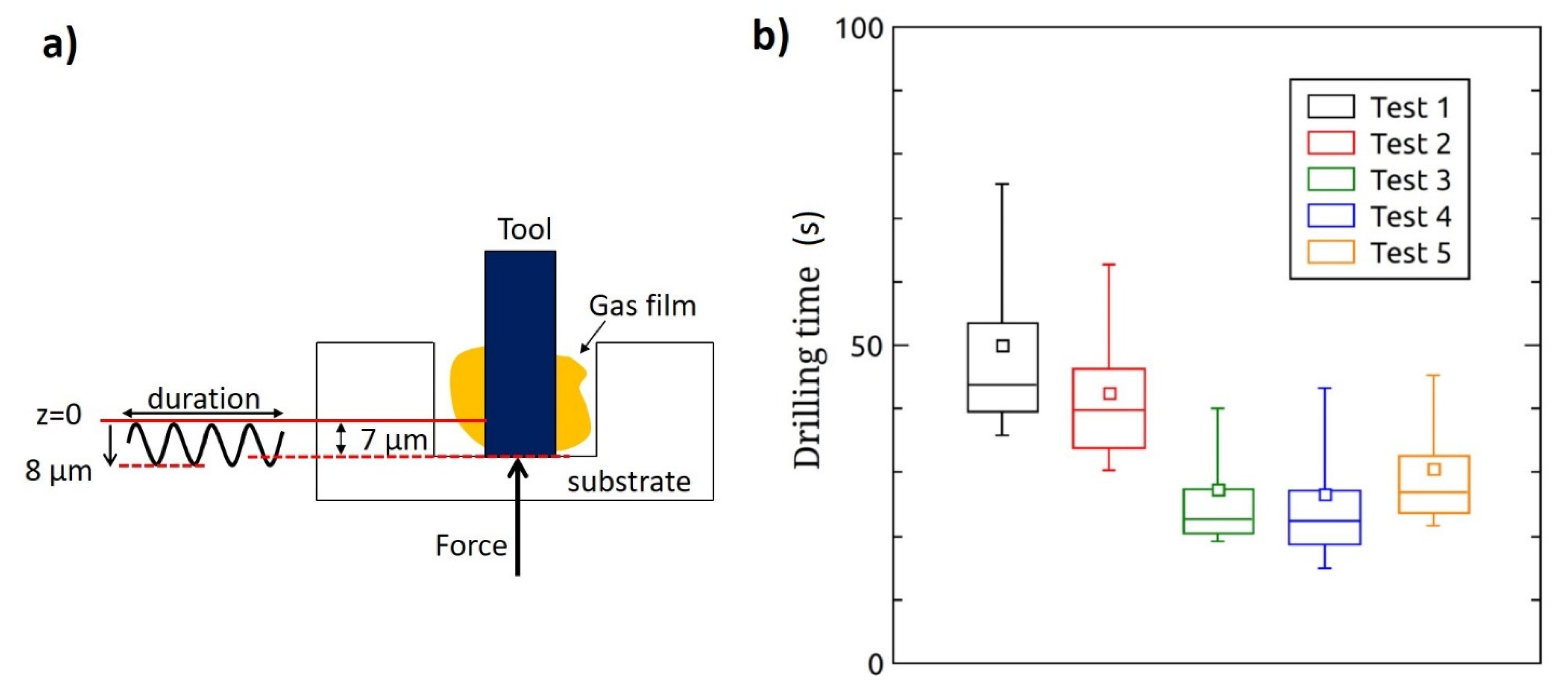
Based on the outcome from the previous experiments, the need arose for a method to flush the machining zone while keeping the generated heat by the discharges as close as possible to the work-piece. For this purpose, tool vibrations were applied. As was performed with the previous experiments, whenever a force above a certain preset threshold was detected while machining, the tool was moved upwards until the force became null. The tool was then moved upwards by a certain gap and vibrations were applied. In this case, one-sided vibrations, in the downward direction, having 8 µm amplitude were applied to the tool once a gap of 7 µm was created in order to force the tool to contact the glass surface during each vibration (
Figure 5a). Therefore, for this algorithm a counter-action means moving the tool upwards whenever a force higher than the threshold is detected until this force is reduced to zero, then creating a 7 µm gap and applying 8 µm amplitude vibrations (downward direction). Different number of vibrations and vibration frequencies per counter-action were investigated, and the results are presented as Test 1 to Test 5 in
Figure 5b.
In Test 1, ten successive vibrations were applied during 1 s per counter-action (thus vibration period was 0.1 s) and the force threshold was 0.8 N. In Test 2, the number of vibrations per counter-action was reduced to two applied vibrations during 0.2 s, hence keeping the same vibration frequency as Test 1, and a shorter drilling time resulted. This shows that applying vibrations during a longer time does not enhance flushing, but rather decelerates the machining speed. This outcome may be explained by the fact that more vibration time means better flushing but reduced surface temperature due to more heat loss. Therefore, in Test 3 more vibrations were applied per counter-action but during a shorter time (10 vibrations during 0.2 s implying that a single vibration period is 0.02 s) to maintain the local heating caused by frequent tool–glass contact. The drilling time was reduced by 15 s compared to Test 2 (two vibrations during 0.2 s; vibration period of 0.1 s) although the total counter-action vibration duration was the same (0.2 s) in both cases. This proves that the high vibration frequency (frequency of tool–glass contact) indeed is crucial to the process. In this case heating is accompanied with flushing duration of 0.2 s.
Upon comparing the drilling time of Test 3 and Test 1 where 10 vibrations were applied during 0.2 s and 1 s, respectively, the number of total counter-actions carried out per hole was the same for both tests. In fact, it turns out that the difference in drilling time between the two tests is the time needed to perform the counter-actions (e.g., 20 counter-actions will take around 20 s for Test 1 versus around 4 s for Test 3 resulting in a time difference of 16 s). Therefore, applying a longer flushing time per counter-action (1 s versus 0.2 s) did not have an effect on the local flushing in the case of a high force threshold of 0.8 N. On the other hand, increasing the frequency of vibrations from 2 to 10 vibrations per counter-action applied during a relatively low flushing time of 0.2 s (i.e., Test 2 versus Test 3) helps reduce the drilling time by improving flushing while maintaining local heating. Hence, tool vibrations have to be carefully applied to accelerate drilling.
To ensure that the effect of vibration frequency is not opposed by the high force threshold chosen, two more tests were conducted where the force threshold was lowered to 0.4 N (Test 4) and 0.2 N (Test 5). For these two tests 10 vibrations were applied during 0.2 s per counter-action (vibration period of 0.02 s). Results showed that the drilling time was slightly reduced for Test 4 whereas it increased again for Test 5. This can be explained by the less efficient heating of the machining zone when a very low force threshold (0.2 N in this case) is used, as shown in
Section 3.1. Therefore, a medium force threshold of 0.4 N showed the best results.
3.5. Enhancing Flushing While Maintaining Heating by Adding Tool Vibration and Rotation
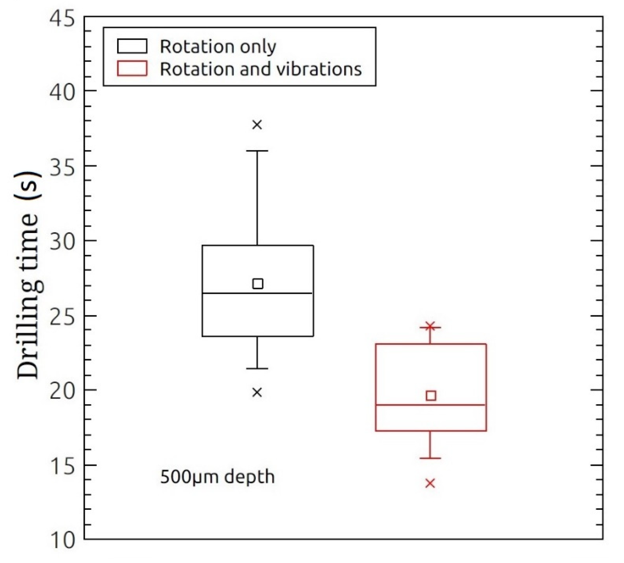
The results of the previous section show that appropriate application of tool vibrations result in local electrolyte flow in the vertical direction. In order to add local fluid motion in the radial direction the tool is additionally rotated. Holes, 500 µm in depth which is almost twice the depth at which the hydrodynamic regime starts, were drilled in less viscous electrolyte (50 wt% KOH) while applying 30 V and a rotation speed of 1000 rpm. The rotation speed was chosen to be moderate such that it would allow local electrolyte flow while not interrupting discharge activity (due to gas film instability at high speeds) for the tool size used. Whenever a force threshold of 0.4 N was exceeded, a counter-action was carried out. The force threshold of 0.4 N was chosen based on the outcome of the previous algorithm. Here, a counter-action refers to moving the tool upwards whenever a force threshold of 0.4 N is exceeded until the force becomes null, then creating a gap of 7 µm, and rotating the tool at 1000 rpm. Results show that drilling time was about 27 s. When the tool was both rotated and vibrated (10 fast vibrations applied during 0.2 s, vibration period of 0.02 s) the drilling time was further reduced (average of 20 s) as shown in
Figure 6. This result shows that by applying both tool rotation and vibration the drilling time is further reduced compared to the case of applying either tool rotation or vibration (
Figure 5b). When applying solely vibration or rotation a drilling time above 25 s results.


