Article

Centimetric-Sized Chromium (III) Oxide Object Synthesized by Means of the Carbon Template Replication

Laboratoire des Nanomatériaux pour Systèmes Sous Sollicitations Extrêmes (NS3E), CNRS-ISL-UNISTRA UMR 3208, Institut franco-allemand de recherches de Saint-Louis (ISL), 5 rue du Général Cassagnou, BP70034, 68301 Saint-Louis, France
Ceramics 2020, 3(1), 92-100; https://doi.org/10.3390/ceramics3010010
Submission received: 9 January 2020 / Revised: 20 February 2020 / Accepted: 28 February 2020 / Published: 5 March 2020

Abstract

:
A simple, efficient synthesis approach for designing large ceramic pieces, herein termed chromium (III) oxide (Cr2O3) material, is provided. The process can be called the replica technique, or replication. The elaboration of a material with a unique morphology is a result of a ceramic salt coating that has been previously dissolved in ethylene glycol as the solvent; this process is performed on a carbon material surface that is selected as a template. Here, the carbon template was carbon fiber. After a heat treatment to convert the ceramic precursor to the corresponding ceramic oxide followed by the removal of the template, hollow ceramic oxide wires were obtained. The resulting material was characterized by X-ray diffraction, Raman and Fourier transform infrared spectroscopies, and scanning electron microscopy. The material exhibited a multiscale architecture, assembling nanosized nodules to form micron-sized tubes that assemble themselves into a centimetric structure. Objects with such tailored architectures can be used in a large variety of applications in fields as diverse as pyrotechnics, adsorption, and catalysis.

1. Introduction

Research in designing inorganic materials with well-defined and controlled multi-scale architectures is ubiquitous in the literature [1]. These shapings largely contribute to improving the existing physicochemical properties of materials, but, sometimes, they reveal unexpected properties of raw materials [2]. These tailoring fabricated architectures are able to revolutionize the application of numerous materials in unsuspected areas and are of interest to a large majority of the materials scientists’ community.
Chromium (III) oxide exhibits many unique properties, making it a candidate for several domains of application such as protective material in front of thermal and abrasive phenomena [3,4]; heterogeneous catalysis, specifically for dehydrogenating alkanes such as propane ((CH3)2CH2) [5]; sensors for different species, like alcohol (ethanol, CH3CH2OH), ketone (acetone, (CH3)2CO), alkane (toluene, C6H5(CH3)), and toxic gases like ammonia (NH3) and dichloride (Cl2) [6,7,8]; and pyrotechnic applications with the creation of energetic composites—where, when mixed with fuel-like aluminum (Al), they react according to a redox reaction and release a large amount of heat (10.9 kJ/cm3) that is tied to a high adiabatic temperature (2054 °C) [9]. Chromium (III) oxide’s global technic capabilities can be enhanced by nanostructuring the matter, allowing for the development of materials with large specific surface areas where the reactive area number is considerably improved, synonymous with optimized performance. To satisfy this permanent requirement of nanostructuring and/or developing complex architectured materials, in particular for the Cr2O3 chromium (III) oxide, many processes have been developed. For instance, Cr2O3 material can be synthesized in the form of spherical nanoparticles [10,11,12,13], nanotubes [6], films [8], and porous matrices by means of soft (surfactants) and hard (mesoporous carbon and silica materials, polymeric building) templates [14,15]. To the best of our knowledge, a nanostructured chromium (III) oxide material that is designed at the macroscale (centimeter) has not yet been proposed in the literature. These kinds of architectures are potentially easier to handle than architectures that exhibit smaller dimensions. Herein, the work is in the same vein as works that have been published in the literature regarding macroscale material synthesis, whose large number spotlights a real interest of the scientific community. For example, oxide ceramic objects (TiO2, ZnO, HfO2, Fe2O3, NiO, SnO2, ZrO2 (stabilized with yttria or not), and SiO2) in the shape of macro- and micron-sized tubes and hollow fibers have already been prepared. They are candidates for applications relating to lithium ion batteries, bacterial filtration, photocatalysis, and ultra-visible microlasers. Some of them are synthesized by means of direct methods, such as electrospinning [16,17], microwaves [18,19], the sol–gel method combined with centrifugal spinning [20], extrusion [21], the self-rolling of gel films [22], or a vapor diffusion route [23]. In all cases, tubes of 0.1–100 µm in diameter with a length of several micrometers were designed. The second approach mentioned in the literature used the well-known hard-template route. For that, different kinds of templates were implemented, such as biomineral ones, like cotton fibers [24,25,26], human hairs [27], vegetal fibers (Platanus acerifolia, Ceiba pentrada, Kapok) [28,29], and calcite [30], as well as synthetic ones like carbon fibers [31,32,33], carbon cloth [34] and glass fibers [35]. These processes allow for the building of materials with tube-like morphologies that exhibit a diameter ranging from 10 to 20 µm, always with lengths of a couple of micrometers. All these investigations evidenced that the synthesis of such architectures, with well-defined textural properties (porosity, surface areas, pore size…), significantly enhanced the performance of the material for the considered application.
Herein, a templated-synthetic route for the elaboration of chromium (III) oxide (Cr2O3) microtubes of centimetric size is reported. The method, inspired by the previous works of C. Vix-Guterl and the author [36,37], uses commercial carbon fibers as a template and coats them with a metal oxide film in order to produce a hollow cylindrical ceramic through carbon template removal. This approach is named the (negative) replica technique because it consists of reproducing or replicating an existing model, herein the carbon fibers. The interest of this synthetic method is to give the opportunity to design large materials that are easy to handle and exhibit interesting textural properties. The carbon template that was used is made of numerous uniform and linear filaments with a 7 µm average diameter. The carbon template was desirable in this study for many reasons: It is commercially available on a large scale, it exhibits a uniform shape and a homogeneous size (diameter can be adjusted from 5 to 20 µm), and it shows good mechanical properties. These criteria seem to us well-suited to the future implementation of a continuous process. Regarding the as-prepared material (Cr2O3) in this investigation, one of the potential applications will be its use as oxidizer, combined with aluminum metal, to formulate energetic composites (thermites) of large dimensions—an emerging research activity in pyrotechnics [38,39,40,41]. The template-synthesized oxide ceramic was submitted to a multiscale characterization.

2. Materials and Methods

Chromium (III) nitrate nonahydrate (Cr(NO3)3·9H2O, 99%) and a chromium (III) oxide nanopowder (Cr2O3, selected as a reference) were purchased from Sigma Aldrich. Ethylene glycol (HOCH2CH2OH, Mw = 62.07 g/mol, d204 = 1.113 g/mL) was obtained from Fluka Chemie AG. Carbon fibers (average diameter = 7.2 ± 0.4 µm) were purchased from Airtech.

2.1. Synthesis of the Cr2O3 Chromium (III) Oxide Tubes

Prior to use, the carbon fibers were cleaned of any organic substances by heating them at 900 °C (15 h) under an argon flow (100 mL/min). Then, the fibers were immersed for one hour in a 2 mol/L chromium (III+)-based ethylene glycol solution before transfer into an alumina boat and heated under air at 500 °C (2 °C/min, 1 h) and then at 800 °C (1 °C/min) for 2 h. While the first heating step assured the conversion of the Cr precursor into a Cr2O3 layer at the carbon fibers’ surface, the second one removed the carbon template to release the Cr2O3 tubular ceramic. The ethylene glycol solvent was desirable due to its ability to chelate metal ions [42]. The chromium (III) oxide phase yield was near 20%.

2.2. Characterization Techniques

X-ray diffraction (XRD) was used to analyze the structure of the as-synthesized sample. The XRD pattern was collected by means of a D8Advance diffractometer (Cu-Kα radiation, λ = 1.5406 Å, Bruker, Billerica, MA, USA) working at 40 kV–40 mA and equipped with a Lynxeye detector. The sample was scanned from angles 20° to 80° with a 2θ step size and times of 0.02° and 0.1 s, respectively. Raman spectra were collected on a InVia confocal microscope (Renishaw, Wotton-under-Edge, Gloucestershire, UK) that was equipped with an Ar+ laser, with a wavelength of 514 nm. The laser was focused on the sample through a x 50 objective, and the spectra were acquired on the 200–2000 cm−1 spectral domain with an exposure time of 10 s and an accumulation of five scans. The laser power (P = 25 mW) was set at 5%. Prior to analysis, a silicon reference was used to calibrate the device. Fourier transform infrared (FTIR) spectroscopy was used to characterize the surface chemistry and the metal–oxygen bonds of the sample. For that, a Tensor 27 spectrometer (Bruker) was used in the transmission mode, and the spectra were recorded in the wavenumber range of 4000–520 cm−1 with a resolution of 4 cm−1 and superposing 16 scans. Prior to the analysis, the sample was mixed with potassium bromide (KBr, 99.99%) and pressed to obtain disks (200 mg, 10 tons, 60 s). The textural properties of the sample were determined by nitrogen sorption measurements (77 K) that were carried out on an Accelerated Surface Area and Porosimetry 2020 analyzer (ASAP 2020, Micromeritics, Norcross, GA, USA). The sample was outgassed at 200 °C (6 h) under vacuum before analysis. The surface area was determined according to the Brunauer–Emmett–Teller (BET) model and applied in the 0.05–0.20 relative pressure domain. The microstructure (morphology, size) of the sample was examined by using a Nova Nano-SEM 450 scanning electron microscope (FEI™, Hillsboro, OR, USA) operating at 10 kV. Gwyddion free software was used to determine carbon fiber and ceramic sample dimensions (diameter and thickness). The values were averaged over at least twenty measures that were randomly taken on at least different places of the materials. Macroscopic views of the pristine sample were obtained with a Canon EOS SDR-R camera.

3. Results and Discussion

Figure 1 shows the X-ray diffraction pattern of the pristine material after the removal of the carbon template. The XRD pattern evidences diffraction peaks that were indexed to a rhombohedra Bravais lattice (corundum structure), with an R-3c space group identifying the Eskolaite chromium (III) oxide phase (Cr2O3), as described in the JCPDS card No. 038–1479 (Figure 1, down). The Miller indices (hkl) characterizing the reticular planes that were defined by the different diffraction peaks present on the pattern are reported in Figure 1. No additional peaks from crystalline secondary phases (impurities) were observed on the investigated angular domain. The broad and very low-intensity peaks located around 23–28° and 40–50° were ascribed to the polymethylmethacrylate sample holder (Figure S1). The crystallite size or coherence length (D) of the Cr2O3 material was determined by using the Scherrer equation:
D = 0.9. λ/(β.cosθ)
where λ is the X-ray wavelength of the radiation, β is the corrected peak width at half-maximum intensity, and θ is the diffraction peak position for the (hkl) considered Miller plane. Taking into account the four most intense peaks, i.e., the (012), (104), (110) and (116) Miller planes, an average crystallite size of 105 ± 22 nm was thus calculated for the Cr2O3 material that was derived from the carbon fiber.
Additional spectroscopic characterizations were performed to confirm the purity of the as-synthesized chromium (III) oxide structure. Figure 2 displays the Raman and the Fourier transform infrared spectra of the as-synthesized Cr2O3 material and the carbon fiber that was used as a template. The spectrum of the chromium-based material (Figure 2A) presented six active Raman peaks, located at 303, 350, 530, 551, 610, and 1400 cm−1. Based on the literature and the commercial Cr2O3 nanopowder Raman spectrum that was taken as a reference (Figure S2) [43], Cr–O stretching modes in the material were considered. While the bands at 303 and 551 cm−1 were attributed to an A1g symmetry mode, the bands at 351, 397, 530, and 609 cm−1 were indexed to an Eg symmetry mode [44]. The Raman spectrum of the carbon fiber material, given in Figure 2B, shows two peaks at 1594 and 1353 cm−1 that are typically attributed to a graphitic (G) carbon material that exhibits some disorders or defects (D) in its structure [45]. The fact that these last peaks were not observed on the templated-Cr2O3 Raman spectrum (Figure 2A) suggests that the chromium oxide material was free of any carbon phase and, accordingly, that the oxidative treatment that was applied during the experimental procedure to remove the carbon template was efficient. The FTIR spectrum of the templated Cr2O3 material shown in Figure 2C is similar to the one that was expected for the Eskolaite phase (α-Cr2O3), as depicted in the Supporting Information 2. Four vibration bands were observed in the 400–800 cm−1 domain, and these corresponded to chromium–oxygen single bonds in stretching vibrations, as noted in the literature [46,47]. The bands at 444 and 569 cm−1 were ascribed to the Eu vibrational mode, while the band at 414 cm−1 was ascribed to the A2u mode. The intense band at 653 cm−1 was attributed to a contribution of the spherical morphology of the particles [47]. At higher wavenumbers, two vibration bands were observed at 1642 and 3000–3500 cm−1. Basically, they can be attributed, respectively, to the (δ) symmetric/antisymmetric bending mode of hydroxyl groups (-OH) and the (υ) stretching mode of water molecules that were physisorbed at the investigated particle’s surface [48]. Other very small vibration bands, observed at wavenumbers of 1000–1300 and 2800–2900 cm−1, were assigned to functional groups (C–O–H, C–O, O–H, and –CH2) and may have originated from the decomposition products of the ethylene glycol solvent. According to the resolution limit of the analysis technique, no further vibration bands were observed, confirming that the as-templated Cr2O3 material was free of any chromium-based amorphous impurities.
Photographs and a scanning electron microcopy analysis were achieved to collect information relating to the macro- and microstructure of the carbon template and the as-templated Cr2O3 material. The representative pictures of both samples are depicted in Figure 3A,B, respectively. Regarding the Cr2O3 sample, a macroscopic voluminous tangle of intense green fibers, with large air gaps, was obtained, as displayed in Figure 3B(1). This result clearly highlights the successful replication of the carbon fibers (Figure 3A(1)) into a ceramic material, as the morphology of the carbon fibers was preserved. As observed, it was possible to design a flexible complex ceramic structure of large dimensions with chromium (III) oxide filaments that may exhibit a length of several centimeters coupled to a strong curvature. However, from a magnified image of this photograph (zoom × 5), displayed in Figure 3B(2), the Cr2O3 filaments seemed to be assembled between themselves and did not show any evidence of being isolated from each other, unlike the carbon filaments that can be observed in Figure 3A(2).
From a scanning electron microscopy analysis, the Cr2O3 fibers are revealed in Figure 3B(3). The filaments were uniform in the long axial direction, with a length of several ten of micrometers and an average diameter in the same order of magnitude as that of the carbon fibers that were selected as the templating agent (Figure 3A(3)). A cross-section of the fibers (Figure 3B(4)) shows that chromia fibers were, in fact, hollow, with an inner diameter of the tubes ca. 6.6 ± 0.3 µm, validating the negative replica concept that was expected from this approach. The fact that this last value was slightly below the average diameter of the carbon fibers may be explained by a structural shrinkage coming from the crystallization of the Cr2O3 material [36,37]. By comparison, a representative cross-sectional image of the carbon fibers shows solid fibers (Figure 3A(4)). In addition, from careful observation of Figure 3A(4),B(4), the inner surface texture of the Cr2O3 tubes matched well with the outer surface aspect of the carbon fibers, highlighting the good adhesion of the chromium-based coating on the carbon fibers’ surface during the dip-coating step. Another microscopic view showing hollow fibers is reported in Figure S3. Figure 4 shows other views of the Cr2O3 hollow fibers where textural aspects are highlighted. For example, Figure 4A shows the thickness of the Cr2O3 walls, which was determined to be around 0.160 ± 0.04 µm. By scrutinizing the wall of the tubes in the long axial direction, an assembly of submicron-sized particles was observed (Figure 4B,C). The particles seemed to adopt a sphere-like morphology that was in agreement with the results of the FTIR analysis, exhibiting a strong vibration band with a shoulder at 653 cm−1. The average particle size was approximately 0.15 µm, and the particles seemed to be sintered between themselves with a minor interparticular porosity, as seen in Figure 4B. The specific surface area of the corresponding hollow Cr2O3 fibers, as determined by means of nitrogen physisorption and taking into consideration the BET model, was 7 m2/g. This value was higher than the specific surface area of the pristine carbon fibers, which was measured below 1 m2/g. Finally, since SEM images and results from BET evidenced larger primary particles than the coherence length that was determined by means of XRD analysis, defects and polycrystallinity inside the Cr2O3 particles were expected.

4. Conclusions

Hollow Cr2O3 chromium (III) oxide ceramic fibers were successfully manufactured from carbon fibers as a template agent in a replication method. The ceramic product, a negative replica of the native carbon molds, showed a centimetric complex architecture made of an assembly of tubes of several thousand micrometrics in length, an inner average diameter of around 6 µm, and a wall thickness of approximately 0.1–0.2 µm. The Cr2O3 tubes comprised the assembly of submicron-sized nodules, allowing for the development of interesting textural properties such as a specific surface area of 7 m2/g. The replica process when implementing such a hard template seems to be efficient and reliable to design ceramic materials (oxides, carbides, nitrides, etc.) that exhibit a specific and controlled morphology at multiscales. The intrinsic properties of the carbon fiber template, as mentioned below, consolidate the idea of a scalable process. Such architectures could potentially be promising in a large variety of applications in diverse fields such as pyrotechnics, adsorption and catalysis. For example, energetic macroscopic objects (thermite) could be created by associating the oxide ceramic piece with an aluminum coating that is deposited by means of a gaseous route.

Supplementary Materials

The following are available online at https://www.mdpi.com/2571-6131/3/1/10/s1, Figure S1: XRD pattern of the polymethylmethacrylate sample holder, Figure S2: Raman and FTIR spectra of a commercial Cr2O3 nanopowder (99.9%), Figure S3: SEM pictures of Cr2O3 hollow fibers synthesized by means of a replication method. Micron-sized carbon fibers were selected as a templating agent.

Funding

The author gratefully acknowledges the French National Centre for Scientific Research (CNRS), French German Research Institute of Saint-Louis (ISL, Saint-Louis, France) and University of Strasbourg (UNISTRA, Strasbourg, France) for funding.

Acknowledgments

The author gratefully acknowledges V. Pichot, F. Schnell (NS3E, Saint-Louis, France) and Y. Boehrer (ISL, Saint-Louis, France) for the assistance in Raman spectroscopy analysis, the scanning electron microscopy analysis and the photographs, respectively.

Conflicts of Interest

The author declares no conflict of interest.

References

  1. Patzke, G.R.; Zhou, Y.; Kontic, R.; Conrad, F. Oxide nanomaterials: Synthetic developments, mechanistic studies, and technological innovations. Angew. Chem. Int. Ed. Engl. 2011, 50, 826–859. [Google Scholar] [CrossRef]
  2. Garcia, Y.; Su, B.L. Introduction to the themed issue on Advanced Complex Inorganic Nanomaterials. New J. Chem. 2014, 38, 1825–1826. [Google Scholar] [CrossRef]
  3. Berdhal, P. Pigments to reflect the infrared radiation from fire. J. Heat Transf. 1995, 117, 355–358. [Google Scholar] [CrossRef]
  4. Kitsunai, H.; Hokkirigawa, K.; Tsumaki, N.; Kato, K. Transitions of microscopic wear mechanism for Cr2O3 ceramic coatings during repeated sliding observed in a scanning electron microscope tribosystem. Wear 1991, 151, 279–289. [Google Scholar] [CrossRef]
  5. Cherian, M.; Rao, M.S.; Yang, W.T.; Jehng, J.M.; Hirt, A.M.; Deo, G. Oxidative dehydrogenation of propane over Cr2O3/Al2O3 and Cr2O3 catalysts: Effects of loading, precursor and surface area. Appl. Catal. A 2002, 233, 21–33. [Google Scholar] [CrossRef]
  6. An, G.; Zhang, Y.; Liu, Z.M.; Miao, Z.J.; Han, B.X.; Miao, S.D.; Li, J.P. Preparation of porous chromium oxide nanotubes using carbon nanotubes as templates and their application as an ethanol sensor. Nanotechnology 2008, 19, 035504–035511. [Google Scholar] [CrossRef] [PubMed]
  7. Wang, Y.; Yuan, X.; Liu, X.; Ren, J.; Tong, W.; Wang, Y.; Lu, G. Mesoporous single-crystal Cr2O3: Synthesis, characterization, and its activity in toluene removal. Solid State Sci. 2008, 10, 1117–1123. [Google Scholar] [CrossRef]
  8. Suryawanshi, D.N.; Patil, D.R.; Patil, L.A. Fe2O3-activated Cr2O3 thick films as temperature dependent gas sensors. Sens. Actuators B 2008, 134, 579–584. [Google Scholar] [CrossRef]
  9. Fischer, S.H.; Grubelich, M.C. Theoretical energy release of thermites, intermetallics, and combustible metals. In Proceedings of the 24th International Pyrotechnics Seminar, Monterey, CA, USA, 27–31 July 1998; pp. 231–286. [Google Scholar]
  10. Gibot, P.; Comet, M.; Eichhorn, A.; Muller, O.; Ciszek, F.; Boehrer, Y.; Schnell, F.; Spitzer, D. Highly insensitive/reactive thermite prepared from Cr2O3 nanoparticles. Propellants, Explos. Pyrotech. 2011, 36, 80–87. [Google Scholar] [CrossRef]
  11. Pei, Z.; Xua, H.; Zhang, Y. Preparation of Cr2O3 nanoparticles via C2H5OH hydrothermal reduction. J. Alloys Compd. 2009, 468, 5–8. [Google Scholar] [CrossRef]
  12. Kim, D.W.; Shin, S.I.; Lee, J.D.; Oh, S.G. Preparation of chromia nanoparticles by precipitation–gelation reaction. Mater. Lett. 2004, 58, 1894–1898. [Google Scholar] [CrossRef]
  13. Gibot, P.; Schnell, F.; Spitzer, D. Ca3(PO4)2 biomaterial: A nontoxic template to prepare highly porous Cr2O3. Mater. Lett. 2015, 161, 172–174. [Google Scholar] [CrossRef]
  14. Dickinson, C.; Zhou, W.; Hodgkins, R.P.; Shi, Y.; Zhao, D.; He, H. Formation Mechanism of Porous Single-Crystal Cr2O3 and Co3O4 Templated by Mesoporous Silica. Chem. Mater. 2006, 18, 3088–3095. [Google Scholar] [CrossRef]
  15. Tüysüz, H.; Weidenthaler, C.; Grew, T.; Lorena Salabaş, E.; Benitez Romero, M.J.; Schüth, F. A crystal structure analysis and magnetic investigation on highly ordered mesoporous Cr2O3. Inorg. Chem. 2012, 51, 11745–11752. [Google Scholar] [CrossRef] [PubMed]
  16. Chen, H.; Wang, N.; Di, J.; Zhao, Y.; Song, Y.; Jiang, L. Nanowire-in-microtube structured core/shell fibers via multifluidic coaxial electrospinning. Langmuir 2010, 26, 11291–11296. [Google Scholar] [CrossRef]
  17. Lang, L.; Xu, Z. Controllable synthesis of porous Fe2O3 microtube and tube-in-tube by non-coaxial electrospinning. Chem. Lett. 2013, 42, 750–752. [Google Scholar] [CrossRef] [Green Version]
  18. Cheng, J.; Guo, R.; Wang, Q.M. Zinc oxide single-crystal microtubes. Appl. Phys. Lett. 2004, 85, 5540–5542. [Google Scholar] [CrossRef] [Green Version]
  19. Jiang, Q.; Liu, Y.; Kan, H.; Yuan, B.; Zhao, H. Microwave-assisted synthesis of hexagonal structure ZnO micro-tubes. Mater. Lett. 2012, 81, 198–201. [Google Scholar] [CrossRef]
  20. Bao, N.; Wei, Z.; Ma, Z.; Liu, F.; Yin, G. Si-doped mesoporous TiO2 continuous fibers: Preparation by centrifugal spinning and photocatalytic properties. J. Hazard. Mater. 2010, 174, 129–136. [Google Scholar] [CrossRef]
  21. Kroll, S.; Brandes, C.; Wehling, J.; Treccani, L.; Grathwohl, G.; Rezwan, K. Highly efficient enzyme-functionalized porous zirconia microtubes for bacteria filtration. Environ. Sci. Technol. 2012, 46, 8739–8747. [Google Scholar] [CrossRef]
  22. Jarvekulg, M.; Valbe, R.; Jogi, J.; Salundi, A.; Kangur, T.; Reedo, V.; Kalda, J.; Maeorg, U.; Lohmus, A.; Romanov, A.E. A sol–gel approach to self-formation of microtubular structures from metal alkoxide gel films. Phys. Status Solidi A. 2012, 209, 2481–2486. [Google Scholar] [CrossRef]
  23. Li, M.K.; Wang, D.Z.; Ding, S.; Ding, Y.W.; Liu, J.; Liu, Z.B. Synthesis and properties of aligned ZnO microtube arrays. Appl. Surf. Sci. 2007, 253, 4161–4165. [Google Scholar] [CrossRef]
  24. Huang, H.; Liu, X.; Huang, J. Tubular structured hierarchical mesoporous titania material derived from natural cellulosic substances and application as photocatalyst for degradation of methylene blue. Mater. Res. Bull. 2011, 46, 1814–1818. [Google Scholar] [CrossRef]
  25. Xie, L.J.; Chu, W.; Huang, Y.Y.; Tong, D.G. Preparation and characterization of biomorphic nickel oxide microtubes templated from cotton. Mater. Lett. 2011, 65, 153–156. [Google Scholar] [CrossRef]
  26. Zhou, X.; Huang, B.; Zou, Y.; Xie, J.; Yang, J. Cotton-templated fabrication of hierarchical SnO2 mesoporous microtubes as the anode material of lithium ion battery. Mater. Lett. 2014, 120, 279–282. [Google Scholar] [CrossRef]
  27. Liu, S.; He, J. Facile fabrication of porous titania microtube arrays by replication of human hair. J. Am. Ceram. Soc. 2005, 88, 3513–3514. [Google Scholar] [CrossRef]
  28. Yang, L.; Li, X.; Wang, Z.; Shen, Y.; Liu, M. Natural fiber templated TiO2 microtubes via a double soaking sol-gel route and their photocatalytic performance. Appl. Surf. Sci. 2017, 420, 346–354. [Google Scholar] [CrossRef]
  29. Hwang, K.J.; Hwang, C.H.; Lee, I.H.; Kim, T.; Jin, S.; Park, J.Y. Synthesis and characterization of hollow metal oxide micro-tubes using a biomaterial template. Biomass Bioenergy 2014, 68, 62–66. [Google Scholar] [CrossRef]
  30. Liu, D.; Yates, M.Z. Fabrication of size-tunable TiO2 tubes using rod-shaped calcite template. Langmuir 2007, 23, 10333–10341. [Google Scholar] [CrossRef]
  31. Motojima, S.; Suzuki, T.; Noda, Y.; Hiraga, A.; Iwanaga, H.; Hashishin, T.; Hishikawa, Y.; Yang, S.; Chen, X. Preparation of TiO2 microcoils from carbon microcoil templates using a sol–gel process. Chem. Phys. Lett. 2003, 378, 111–116. [Google Scholar] [CrossRef]
  32. Liu, X.; Du, H.; Sun, X.W.; Liu, B.; Zhao, D.; Sun, H. Visible-light photoresponse in a hollow microtube–nanowire structure made of carbon-doped ZnO. CrystEngComm. 2012, 14, 2886–2890. [Google Scholar] [CrossRef]
  33. Valtchev, V.; Schoeman, B.J.; Hedlund, J.; Mintova, S.; Sterte, J. Preparation and characterization of hollow fibers of silicalite-l. Zeolites 1996, 17408, 408–415. [Google Scholar] [CrossRef]
  34. Indra, A.; Paik, U.; Song, T. Boosting Electrochemical Water Oxidation with Metal Hydroxide Carbonate Templated Prussian blue Analogues. Angew. Chem. Int. Ed. 2018, 57, 1241–1245. [Google Scholar] [CrossRef] [PubMed]
  35. Liu, W.; Zhang, L.; Cao, L.X.; Su, G.; Wang, Y.G. Glass fibers templated preparation of TiO2 microtubes assembled from nano/micro hierarchical TiO2 crystals. J. Alloys Compd. 2011, 509, 3419–3424. [Google Scholar] [CrossRef]
  36. Vix-Guterl, C.; Alix, I.; Gibot, P.; Ehrburger, P. Formation of tubular silicon carbide from a carbon–silica material by using a reactive replica technique: Infra-red characterization. Appl. Surf. Sci. 2003, 210, 329–337. [Google Scholar] [CrossRef]
  37. Gibot, P.; Vix-Guterl, C. TiO2 and [TiO2/SiC] microtubes prepared from an original process. J. Eur. Ceram. Soc. 2007, 27, 2195–2201. [Google Scholar] [CrossRef]
  38. Wang, A.; Bok, S.; Thiruvengadathan, R.; Gangopadhyay, K.; McFarland, J.A.; Maschmann, M.R.; Gangopadhyay, S. Reactive nanoenergetic graphene aerogel synthesized by one-step chemical reduction. Combust. Flame. 2018, 196, 400–406. [Google Scholar] [CrossRef]
  39. Comet, M.; Martin, C.; Schnell, F.; Spitzer, D. Nanothermite foams: From nanopowder to object. Chem. Eng. J. 2017, 316, 807–812. [Google Scholar] [CrossRef]
  40. Yang, S.; Jian, G.; Zachariah, M.R. Electrospun nanofiber-based thermite textiles and their reactive properties. ACS Appl. Mater. Interfaces. 2012, 4, 6432–6435. [Google Scholar]
  41. Yang, Y.; Zhang, Z.C.; Wang, P.P.; Zhang, J.C.; Nosheen, F.; Zhuang, J.; Wang, X. Hierarchical MnO2/SnO2 heterostructures for a novel free-standing ternary thermite membrane. Inorg. Chem. 2013, 52, 9449–9455. [Google Scholar] [CrossRef]
  42. Dong, H.; Chen, Y.-C.; Feldmann, C. Polyol synthesis of nanoparticles: Status and options regarding metals, oxides, chalcogenides, and non-metal elements. Green Chem. 2015, 17, 4107–4132. [Google Scholar] [CrossRef]
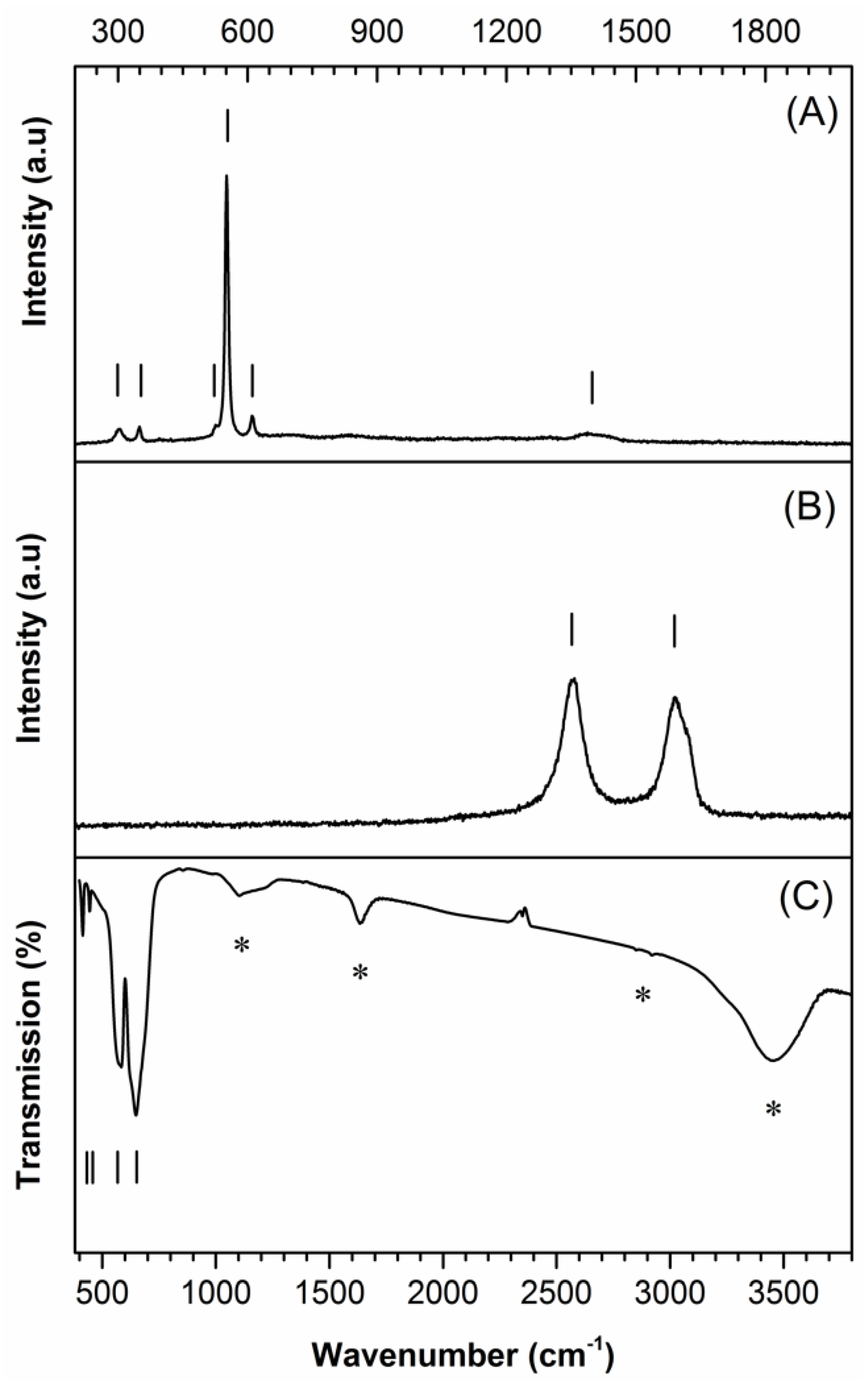
  43. Shim, S.H.; Duffy, T.S.; Jeanloz, R.; Yoo, C.S.; Iota, V. Raman spectroscopy and x-ray diffraction of phase transitions in Cr2O3 to 61 GPa. Phys. Rev. B Solid State 2004, 69, 144107–144119. [Google Scholar] [CrossRef] [Green Version]
  44. Mougin, J.; Le Bihan, T.; Lucazeau, G. High-pressure study of Cr2O3 obtained by high-temperature oxidation by X-ray diffraction and Raman spectroscopy. J. Phys. Chem. Solids 2001, 62, 553–563. [Google Scholar] [CrossRef]
  45. Ferrari, A.C.; Robertson, J. Interpretation of Raman spectra of disordered and amorphous carbon. Phys. Rev. B Solid State 2000, 61, 14095–14107. [Google Scholar] [CrossRef] [Green Version]
  46. Musi, S.; Maljkovi, M.; Popovi, S.; Trojko, R. Formation of chromia from amorphous chromium hydroxide. Croat. Chem. Acta 1999, 72, 789–802. [Google Scholar]
  47. Serna, C.J.; Rendon, J.L.; Iglesias, J.E. Infrared surface modes in corundum-type microcrystalline oxides. Spectrochim. Acta 1982, 38, 797–802. [Google Scholar] [CrossRef]
  48. Available online: https://webbook.nist.gov/cgi/cbook.cgi?ID=C7732185&Type=IR-SPEC&Index=1#IR-SPEC (accessed on 3 March 2020).
Figure 1. XRD pattern of the as-templated Cr2O3 material (top pattern). For comparative purposes, the diffraction profile of the Cr2O3 Eskolaite phase is shown (bottom pattern) (JCPDS No. 038-1479).
Ceramics 03 00010 g001
Figure 2. (A,C) Raman and Fourier transform infrared (FTIR) spectra, respectively, of the as-templated Cr2O3 material and (B) the Raman spectrum of the carbon fiber that was used as template. In the FTIR spectrum of Cr2O3, all the vibration bands related to the chromium–oxygen bonds are noted by means of vertical lines, while a star symbol is used to identify the solvent traces and/or moisture that were adsorbed at the particles surface.
Ceramics 03 00010 g002
Figure 3. Photographs (1–2) and SEM views (3–4) of the (A) carbon fiber template and (B) as-templated Cr2O3 material.
Ceramics 03 00010 g003
Figure 4. SEM views of the Cr2O3 hollow fiber material: (A) thickness and (B,C) axial direction views.
Ceramics 03 00010 g004

