3.1. Burner Rig Fatigue Test Results
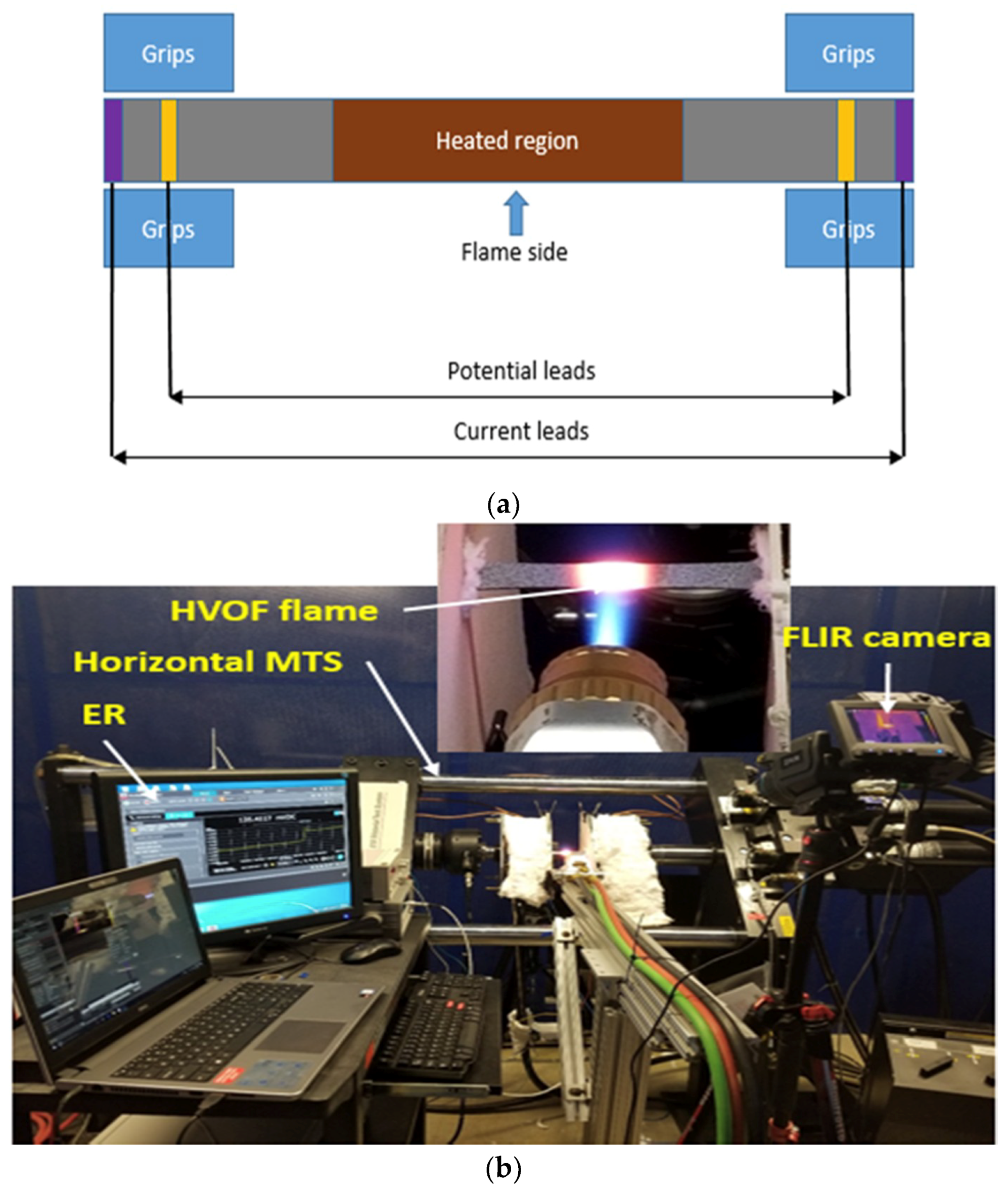
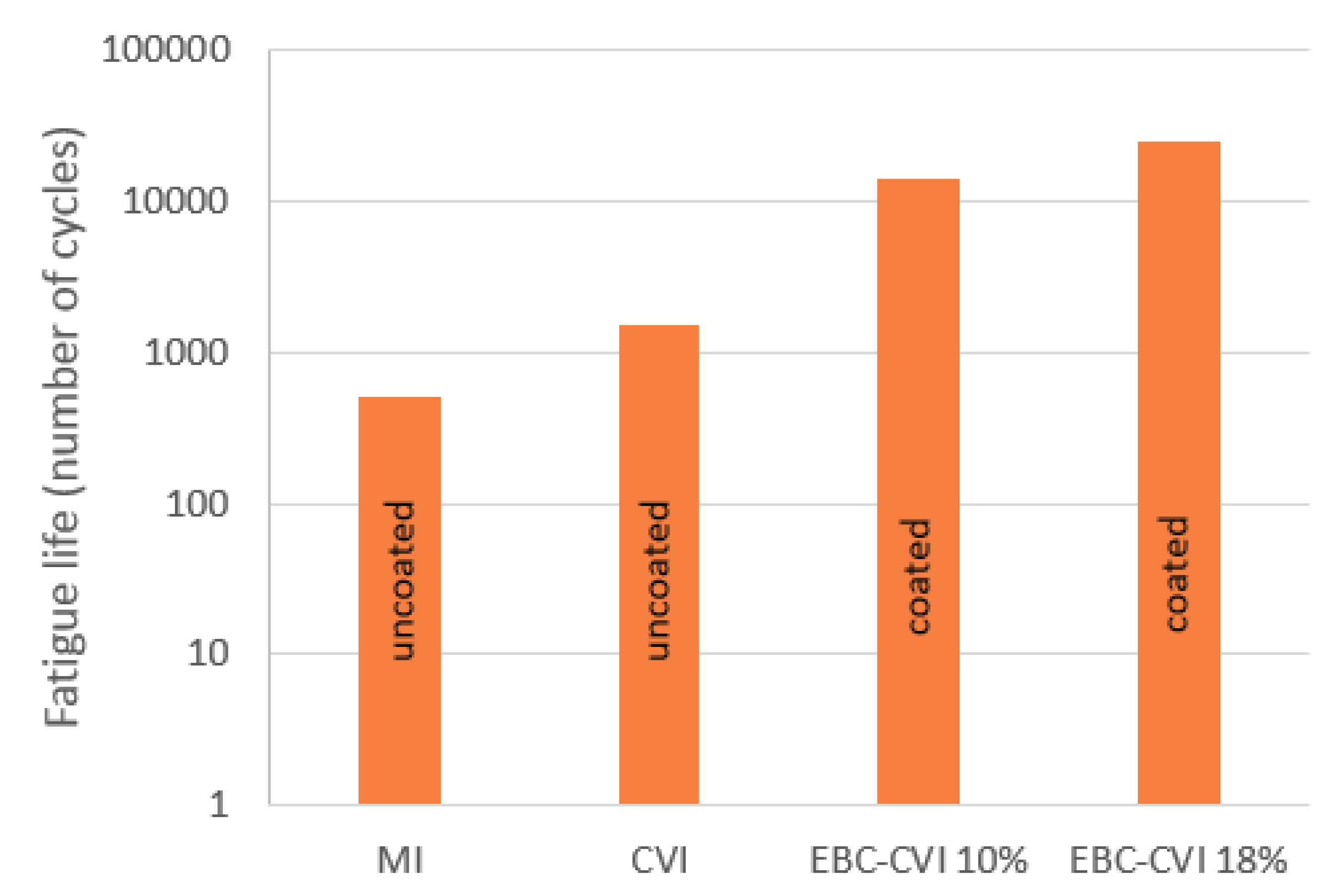
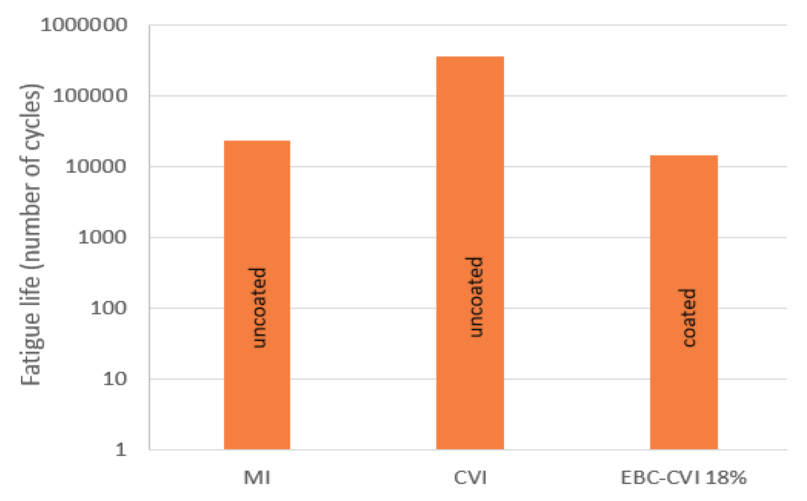
Uncoated MI, CVI, and environmental barrier coating (EBC) coated CVI test coupons were tested in tension-tension fatigue loading at a peak stress of 100 MPa with combustion flame impinging on front surface. In this study fatigue life of the specimens considered is defined up to failure. Fatigue life of the test coupons tested in combustion environment is shown in
Figure 3. Uncoated specimens had a shorter fatigue life compared to the EBC coated. Shorter fatigue life of the uncoated test coupons indicates the adverse effect of harsh combustion environment.
Fatigue life of 500 cycles (8 min) was observed for the MI specimen. It should be noted that the MI specimens used here were relatively weak compared to modern state-of-the-art MI composites, which could be a reason for such a low fatigue life. The uncoated CVI specimen survived 1500 cycles (25 min) while the EBC coated CVI specimens with 10% and 18% porosity content survived 14,400 cycles (240 min) and 25,200 cycles (420 min). Application of EBC coating significantly increased the fatigue life in combustion environment. Presence of voids, the exposure of as-machined edges, and the 45° angle of incidence of the flame most likely accelerated material degradation. Comparing the two EBC coated CVI specimens, specimen with high porosity (18%) content showed a significant increase in fatigue life. This may be due to the increased infiltration of oxide into the composite. In addition, prior to testing some regions along the edges of the EBC-CVI 10% specimen were observed to not completely cover the edge exposing the as-machined edges to the environment. Also, presence of micro-cracks on the EBC coating due to slurry infiltration technique makes them more susceptible to spallation where oxidative gases can easily reach the substrate.
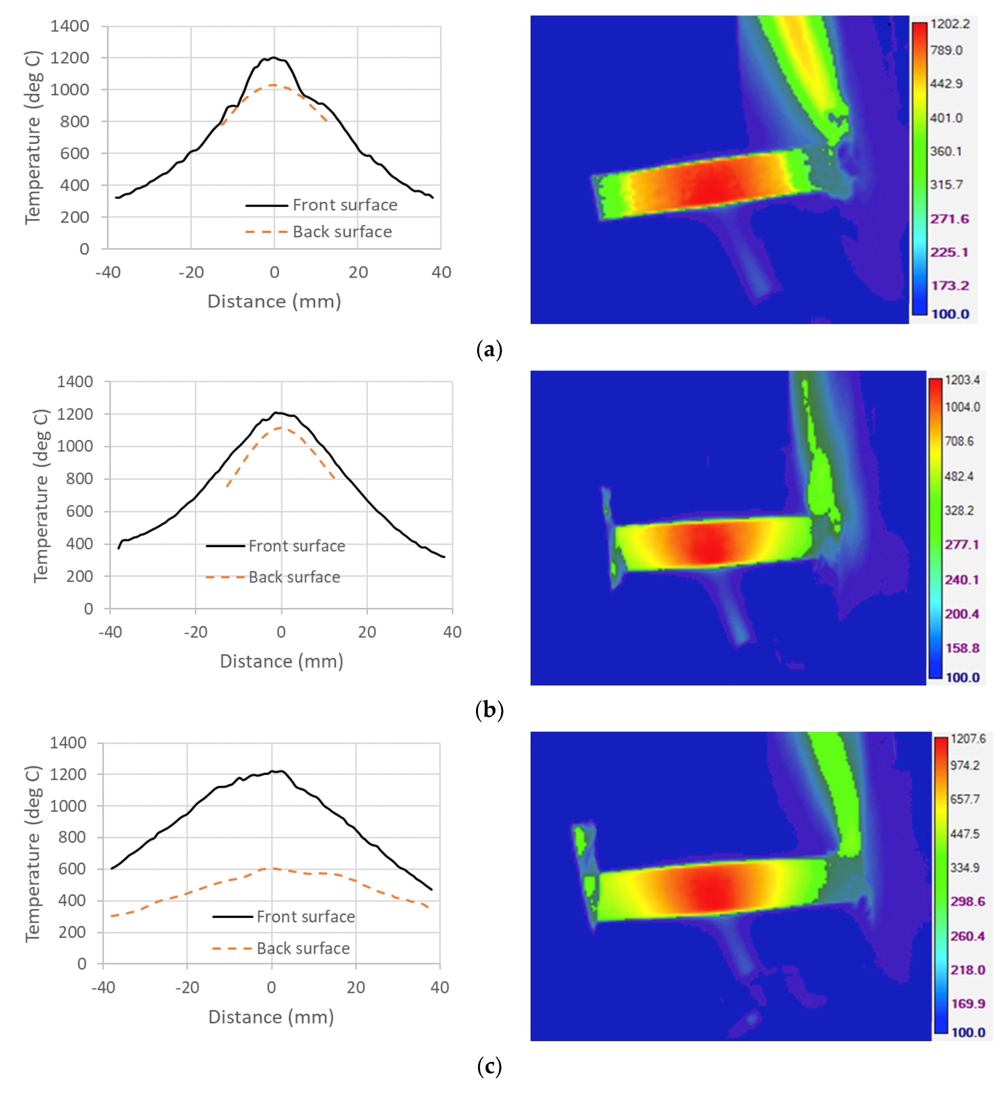
Temperature distribution along the length of the specimen for coated and uncoated test coupons are shown in
Figure 4. Front side FLIR camera captured the entire gauge section while the back side FLIR camera captured only an inch length because of different calibration settings. A thermal gradient of 175 °C, 100 °C, and 600 °C is seen for MI, CVI, and EBC coated CVI. From the literature [
1], it is observed that MI SiC/SiC has higher thermal conductivity compared to CVI SiC/SiC. However, the CVI specimens tested in this study are thinner (
Table 1) than the MI specimens which would explain the lower thermal gradient for CVI.
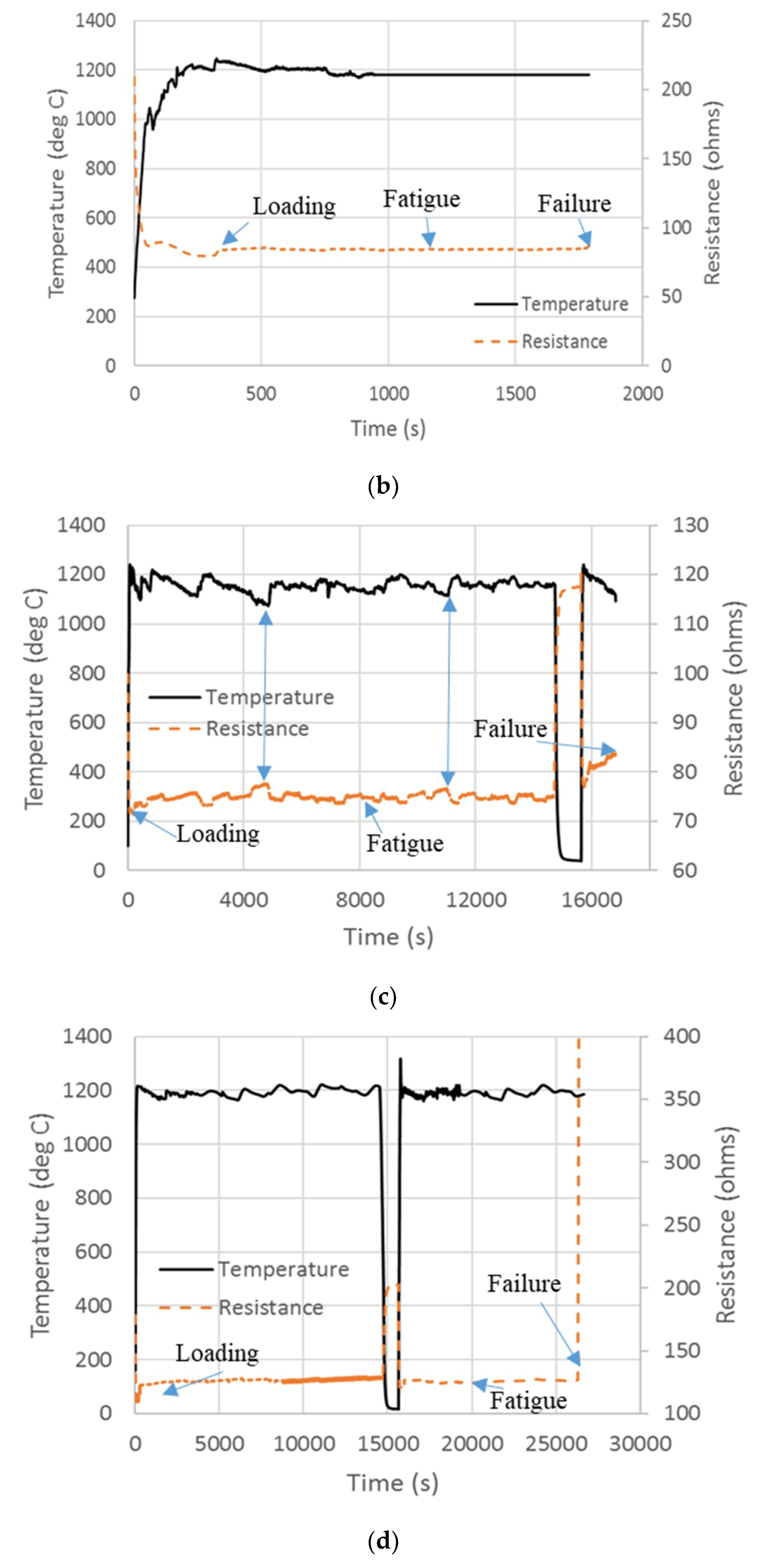
Resistance change with temperature for the uncoated and EBC coated test coupons are shown in
Figure 5. To understand the ER behavior, the current flow path for the two material systems considered in this study has to be explained. Many researchers [
17,
20,
21,
22] have extensively investigated the ER behavior of MI and CVI SiC/SiC CMC systems at room temperature and high temperature under various loading conditions. MI composites are electrically more conductive compared to the CVI. In MI SiC/SiC, the matrix is the more conducting phase in comparison to the fiber. This is due to the presence of free doped silicon (Si) present in the matrix. Si is more conductive than that of the pure CVI. Morscher et al [
17] estimated the resistivity of Si to be 0.046 Ω-mm for iBN composite and 0.056 Ω-mm for ZMI composite. Any damage to the matrix (i.e., matrix cracking) breaks the electrical network resulting in an overall increase in the resistance. The literature reported resistivity values of the CMC constituents are listed in
Table 4 [
17,
23,
24]. CVI SiC/SiC considered in this study had Hi-Nicalon fibers. From
Table 4, it can be seen that resistivity of Hi-Nicalon fibers is significantly lower compared to the pure CVI SiC, and it is reasonable to assume that fibers are the majority charge carriers. Therefore, CVI SiC/SiC system is less sensitive to matrix damage compared to MI SiC/SiC.
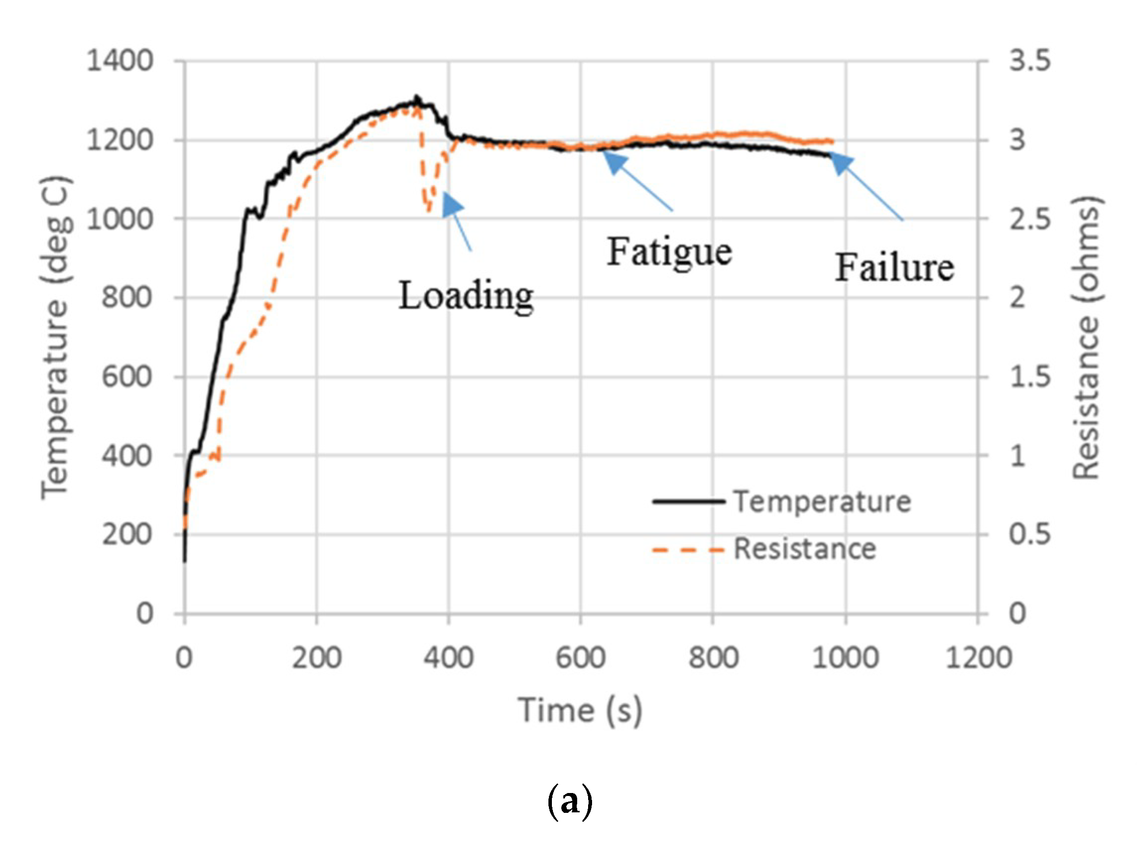
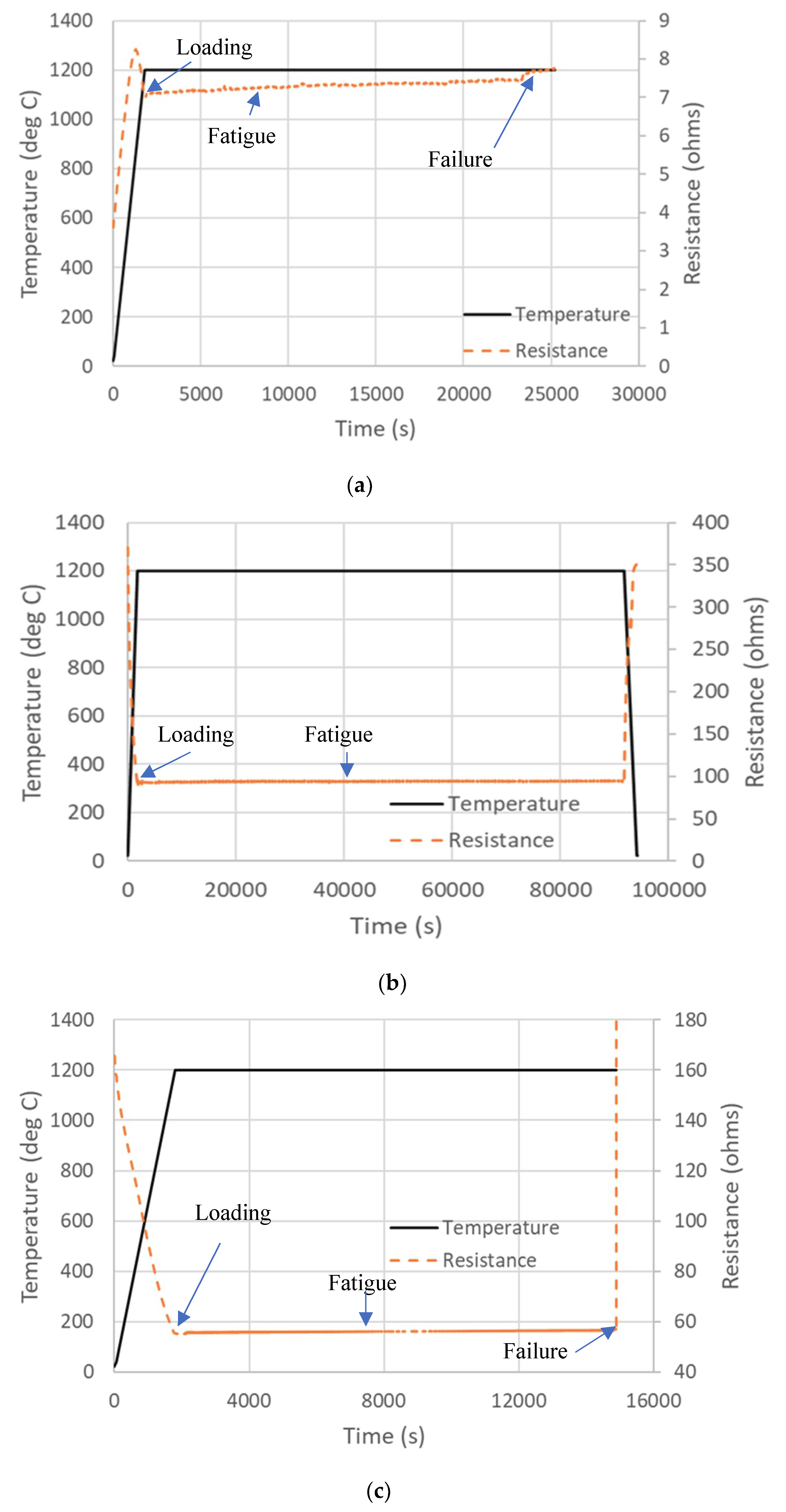
The high-temperature ER response of the MI SiC/SiC system is significantly different compared to the CVI SiC/SiC due to the presence of silicon enriched matrix. Resistance of Si increases with temperature, whereas the resistance of SiC decreases with temperature. Similar ER behavior, as discussed above, is observed in the burner rig for MI and CVI SiC/SiC composites, respectively (
Figure 5). MI composite resistance significantly increased with heating and upon loading a more gradual increase in resistance was observed until failure (
Figure 5a). CVI composite resistance significantly decreased with heating and an increase in resistance is seen with loading (
Figure 5b–d). This gradual increase in resistance could be attributed to fatigue loading and possible oxidative degradation [
25].
For one of the EBC coated CVI SiC specimens (
Figure 5c), there were intermittent increases and decreases in resistance during burner rig fatigue. The increases corresponded with temperature decreases and the decreases with temperature increases, showing the sensitivity of resistance to temperature fluctuations possible due to open-flame heating. The resistance of the specimens before, during, and just prior to failure in burner rig is shown in
Table 5. Some measurements were made at room temperature (RT) and others at temperature. An increase in resistance was observed for all the CVI specimens at temperature and the CVI-EBC specimens after 4 h of testing when measured at room temperature. This residual or irreversible resistance is presumed to be due to nonrecoverable damage to the fibers and matrix. The MI specimen actually showed a little net increase in resistance at temperature. However, this was probably due to the apparent gradual reduction in temperature during the test (
Figure 5a).
3.2. Furnace Testing
To compare to the combustion test results, test coupons were tested in isothermal furnace at a peak temperature (1200 °C), the same as the surface temperature of the combustion test. Fatigue life of the uncoated and coated specimens is shown in
Figure 6. The fatigue life for MI was 6.5 h (23,400 cycles); for CVI as-produced, it was 100 h (360,000 cycles); and for the EBC coated CVI, it was 4 h (14,400 cycles). Furnace tested specimens showed a significant increase in fatigue life compared to the combustion tested uncoated specimens. Higher fatigue life observed in the furnace could be due to the absence of water vapor and thermal gradient stresses. Higher fatigue life seen for the EBC-CVI 18% porosity specimen in burner rig compared to furnace tested specimen could be due to increased infiltration of oxide into the composite. The significance of thermal gradinet stress and watervapor on fatigue life is discussed in detail in the ”General discussion” section.
Surprisingly, the uncoated CVI significantly outperformed the EBC coated CVI for the furnace fatigue condition. EBC coating processing required sintering at 1450 °C for several hours. Heat-treating the composite for such a long duration exposes the Hi-Nicalon fibers to temperatures well above their processing temperature and is known to degrade the fiber strength by 60% [
26,
27,
28,
29]. This suggests that application of EBC coating using slurry infiltration technique provides the oxidation resistance but significantly reduces the fiber strength for this composite system due to thermal exposure during coating processing. However, if Hi-Nicalon S fibers were used in the CVI SiC system, such degradation would not be expected.
ER profiles with temperature for the MI, CVI, and EBC coated CVI specimens are shown in
Figure 7. For the MI specimen, resistance increased with heating up to 950 °C and beyond this resistance decreased. Smith et al [
23] reported that resistivity of silicon varies with dopant level and there is a saturation temperature where the resistance increases with time (below the saturation temperature) and above saturation temperature resistance decreases. The increase in resistance below the saturation temperature is attributed to the precipitation of dopants from the silicon and the decrease above saturation temperature is attributed to the increase in carrier concentration due to reabsorption of dopants.
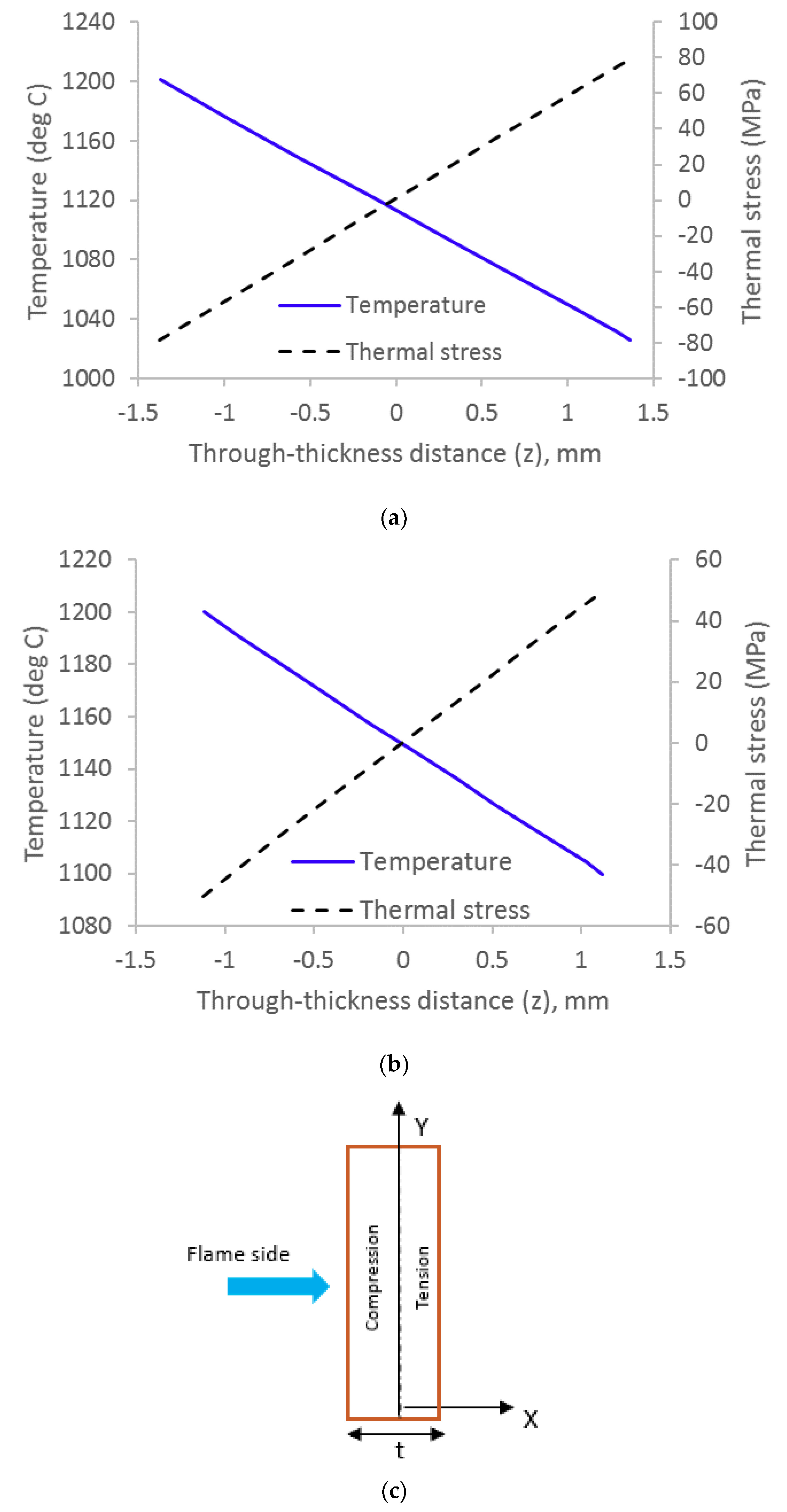
This behavior is not seen in the burner rig MI specimens, which we believe to be due to difference in the temperature distribution along the length of the specimen. The three-inch furnace and the burner rig both have a hot zone (1200 °C) of approximately 25 mm (
Figure 4). However, the furnace temperature both within and outside the hot zone is uniform across the cross-section of the composite and the axial temperature gradient is relatively stable. The burner rig has a temperature gradient through the thickness of the specimen so that the hottest region of the specimen is at the surface of the flame side. The resistivity of the regions outside the flame-side surface are higher for temperatures from ~900 to 1200 °C. These high resistances presumably would mask the decrease in resistance experienced in the hot zone above the saturation temperature, resulting in a continuous increase in resistance. With loading, an increase in resistance is seen, and finally, failure where resistance changes is abrupt. Observed ER trend for CVI and EBC coated CVI composite in furnace is similar to the burner rig where the resistance decreased with heating and with loading resistance increased until failure.
ER change in furnace tested specimens is shown in
Table 6. Uncoated CVI specimen showed no change in ER after 100 h of testing, which implies that the applied stress did not cause any significant matrix cracking to the composite. The smooth ER trend in the furnace is due to uniform increase of temperature.
3.3. Microscopic Analysis
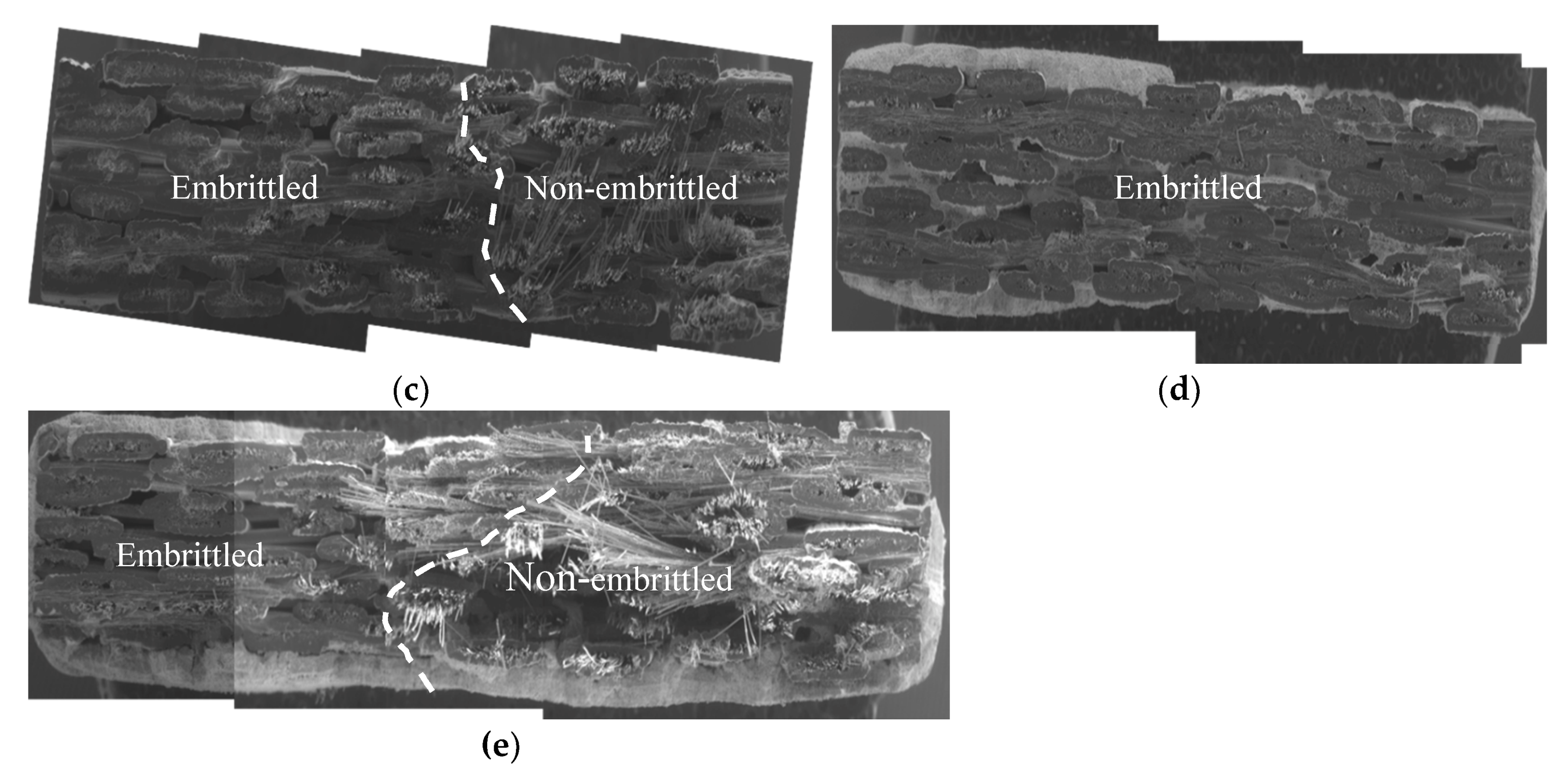
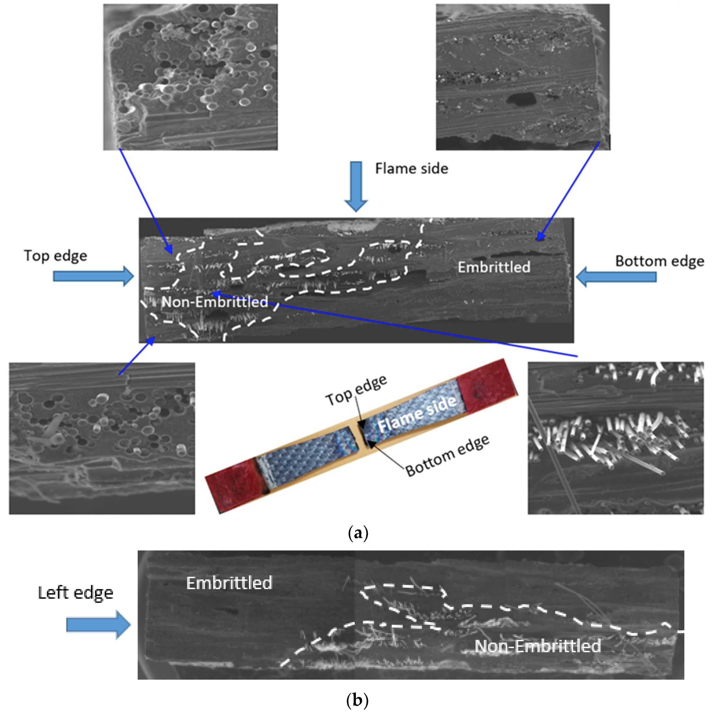
Fracture surfaces of the failed test coupons were observed under SEM to understand the damage mechanisms and the extent of oxidation. Microscopy images of fracture surfaces of MI, CVI, and EBC coated CVI test coupons tested under combustion and furnace conditions are shown in
Figure 8.
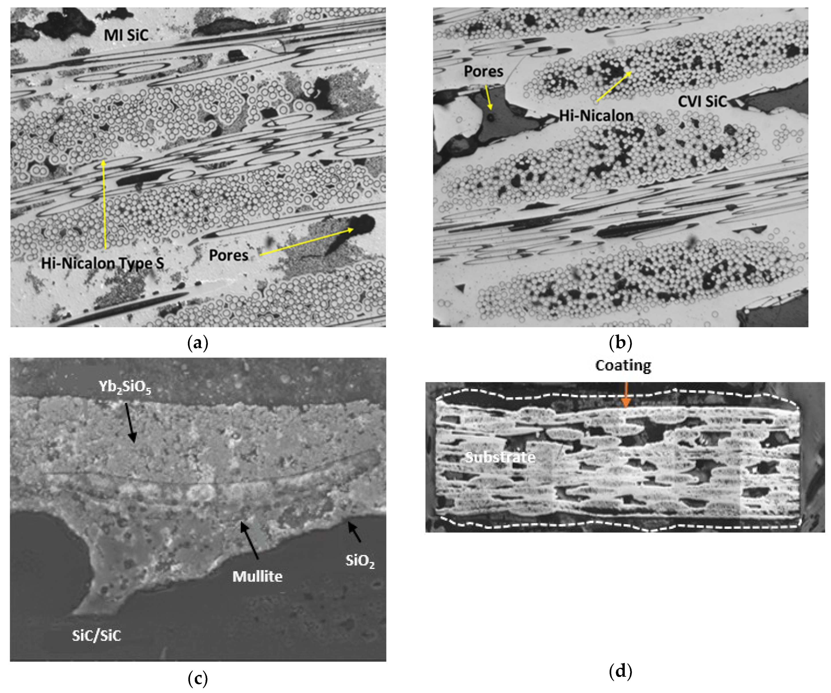
From SEM images, it is clearly evident that majority regions of the fracture surface of the test coupons tested in combustion facility (
Figure 8a,c) are oxidized with little fiber pullout. Oxidized regions are indicated as embrittled and unoxidized/fiber pullout regions are indicated as non-embrittled. The two regions are separated by a white dotted line. In oxidized regions, matrix and the BN interphase are completely oxidized, and the fibers are fused together by the oxides, whereas no signs of oxidation are seen on the fibers in the pullout area. Burner rig test coupons suffered significant oxidation, which could be attributed to the hostile environment with harsh combustion gases. Edges of the test coupons (
Figure 8a) tested in combustion environment are completely oxidized clearly indicating an edge effect. Edge effect is predominantly seen in burner rig due to angular impingement (45°) of flame on test coupons. As a result, top and bottom edges of the specimen were completely exposed to high temperature high velocity flame. It appears that loading initiated micro-cracks, which serve as a free path for the high-temperature gases to enter the composite system, causing embrittlement and finally a dominant crack is originated from the edges.
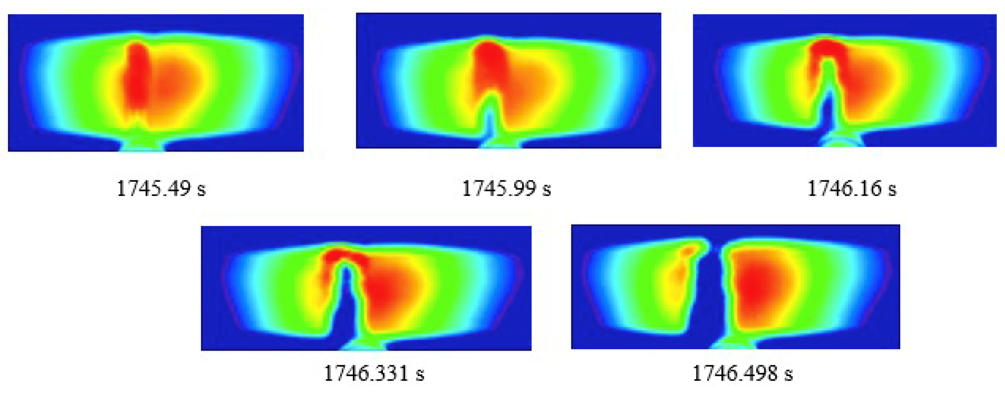
Figure 9 shows the FLIR image of the CVI test coupon near failure in burner rig indicating the failure from the bottom edge. This is consistent with the fracture surface (
Figure 8a) where the embrittled region extends more deeply from the bottom edge (nearest to nozzle) than the top edge.
Fracture surface of the EBC coated CVI specimens (
Figure 8d) showed a planar fracture with no fiber pullout and complete oxidation of BN interphase. Application of EBC coating increased the fatigue life of the specimen. However, coating spallation, which leads to the exposure of the as-machined edges, formation of micro-cracks due to loading, and longer time for the cracks to propagate, made the hot combustion gases diffuse through the cracks leading to complete oxidation of fibers and matrix.
For the furnace tested specimen, oxidation likely appeared to be originated from the left edge (
Figure 8b,e) and a little fiber pullout is seen on the other edge. In the oxidized areas, BN interphase is completely oxidized, causing fibers to bond together, whereas no oxidation is seen on fibers in non-embrittled areas. Fracture surface reveals that cracks are initiated from the machined edges. As the crack grows, more regions are exposed to oxidative environment, causing embrittlement. Presumably embrittled areas transfer the load to remaining intact areas, which are incapable of carrying the load leading to final failure [
30,
31].

 ,
, 


