1. Introduction
Advancements in aerospace technology heavily depend on the development of structural materials that maintain mechanical performance at elevated temperatures. Examples of components that are exposed to extreme temperature environments include engine-related components and thermal protection systems. Metals and metallic super-alloys have been developed to increase the temperature capability, but their melting temperatures are being met and exceeded by current and future operating conditions. Ceramics possess excellent high-temperature characteristics, high strength and hardness, chemical inertness, wear resistance, and low density. However, the absence of energy-dissipating mechanisms in ceramics causes catastrophic failure and it precludes their use as structural components. The incorporation of reinforcements in a ceramic matrix, which form a ceramic matrix composite (CMC), has been found to drastically improve the fracture toughness over that of ceramics [
1]. CMCs provide a combination of the outstanding thermal and mechanical properties of ceramics with an increased fracture toughness being afforded by the reinforcement phase [
2]. CMCs are mainly used in the hot section components of the aero engine, including intermediate temperature/load components (i.e., tail nozzles, etc.), high temperature/intermediate load components (i.e., combustion chamber, afterburner, turbine outer ring, turbine guide vanes, etc.), and high temperature/load components (i.e., turbine blades, etc.) [
3]. However, the development of CMCs is in the relatively early stages, and there exists much work to be done in the identification, testing, and characterization of CMCs under a variety of conditions.
Many researchers performed experimental and theoretical investigations on matrix cracking of fiber-reinforced CMCs. The energy balance approach that was suggested by Aveston, Cooper, and Kelly [
4], Aveston and Kelly [
5], Budiansky, Hutchinson and Evans [
6], Chiang [
7], Rajan and Zok [
8], and Li [
9,
10], and the fracture mechanics approach that was proposed by Marshall, Cox, and Evans [
11], McCartney [
12], Chiang [
13], Cox and Marshall [
14], and Deng et al. [
15], and the stochastic matrix cracking approach that was developed by Ahn and Curtin [
16], Lissart and Lamon [
17], and Lamon [
18], and the critical matrix strain energy (CMSE) approach that was developed by Solti, Mall, and Robertson [
19] and Li [
20]. Morscher et al. [
21] established the relationships for stress-dependent matrix cracking of two-dimensional (2D) Hi-Nicalon
TM and Sylramic
TM-iBN SiC fiber-reinforced chemical vapor infiltrated (CVI) SiC matrix composites, which were related to the stress in the load-bearing CVI SiC matrix. Xia et al. [
22] developed a coupled electro-mechanical model to predict the matrix cracking of a 2D SiC/SiC composite. The electrical resistance is capable of monitoring damage due to the change in the flow of current through the material when the matrix cracks form and linearly increases with matrix crack density and the number of fiber breaks. Simon et al. [
23] developed the electrical model as a network of resistor cells and established a relationship between the electrical resistance and matrix cracking density and debonding density. Li [
24,
25] investigated the tensile behavior of fiber-reinforced CMCs with different fiber preforms when considering the matrix multi-cracking, interface debonding, and fibers failure. The matrix cracking evolution, saturation matrix cracking stress and density affect the non-linear behavior of CMCs. Under cyclic fatigue loading, the fiber/matrix interface debonding and sliding occurred between matrix crack spacing, leading to interface wear [
26,
27]. Li et al. [
28] investigated the effect of interface bonding properties on cyclic tensile behavior of unidirectional C/Si
3N
4 and SiC/Si
3N
4 composites. The degradation of the interface properties affects the area and shape of the hysteresis loops. The difference of fiber/matrix interface shear stress existed between the interface wear region and the interface debonding region affects matrix multiple cracking evolution with applied stress. Based on the CMSE criterion [
19], the matrix cracking density of fiber-reinforced CMCs remains constant under cyclic fatigue loading. However, after the cyclic fatigue loading, the matrix cracking density will increase at the higher stress level than the fatigue peak stress. Simon et al. [
29] investigated the behavior of a SiC/[Si-B-C] composite that was tested under air at 450 °C and static and cyclic fatigue conditions, while using electrical resistivity and acoustic emission measurements in order to monitor the ageing of the material. The progression of oxidation through the material could be successfully monitored through the electrical resistivity; however, the matrix cracking density has not been discussed in detail. However, in the studies mentioned above, the effect of cyclic fatigue loading on matrix cracking density of fiber-reinforced CMCs has not been investigated.
In this paper, the effect of cyclic fatigue loading on matrix multiple fracture of fiber-reinforced CMCs is investigated based on the CMSE criterion. When combining with the fiber/matrix interface wear model and fracture mechanics interface debonding criterion, the shear-lag model is adopted to analyze the fiber and matrix axial stress distribution inside of damaged composite. The relationships between multiple matrix cracking, cyclic fatigue peak stress, fiber/matrix interface wear, and debonding are established. The effects of fiber volume fraction, fiber/matrix interface shear stress, and applied cycle number on matrix multiple fracture and fiber/matrix interface debonding and interface wear are discussed. Comparisons of multiple matrix cracking with/without cyclic fatigue loading are analyzed. The experimental matrix cracking of unidirectional SiC/CAS, SiC/SiC, SiC/Borosilicate, and mini-SiC/SiC composites with/without cyclic fatigue loading are predicted. The proposed model applies at ambient temperatures and it excludes any chemical degradation effect.
3. Results and Discussions
The ceramic composite system of unidirectional SiC/CAS is used for the case study and its material properties are given by: Vf = 30%, Ef = 200 GPa, Em = 97 GPa, rf = 7.5 μm, ξm = 6 J/m2, ξd = 0.8 J/m2, τi = 25 MPa, τf = 5 MPa, αf = 4 × 10⁻⁵/°C, αm = 5 × 10⁻⁵/°C, ΔT = −1000 °C. The effects of fiber volume fraction, fiber/matrix interface shear stress and applied cycle number on matrix cracking density, fiber/matrix interface debonded length, fiber/matrix interface debonding ratio, and fiber/matrix interface wear ratio are discussed. The comparisons of matrix cracking with and without fatigue loading are also analyzed.
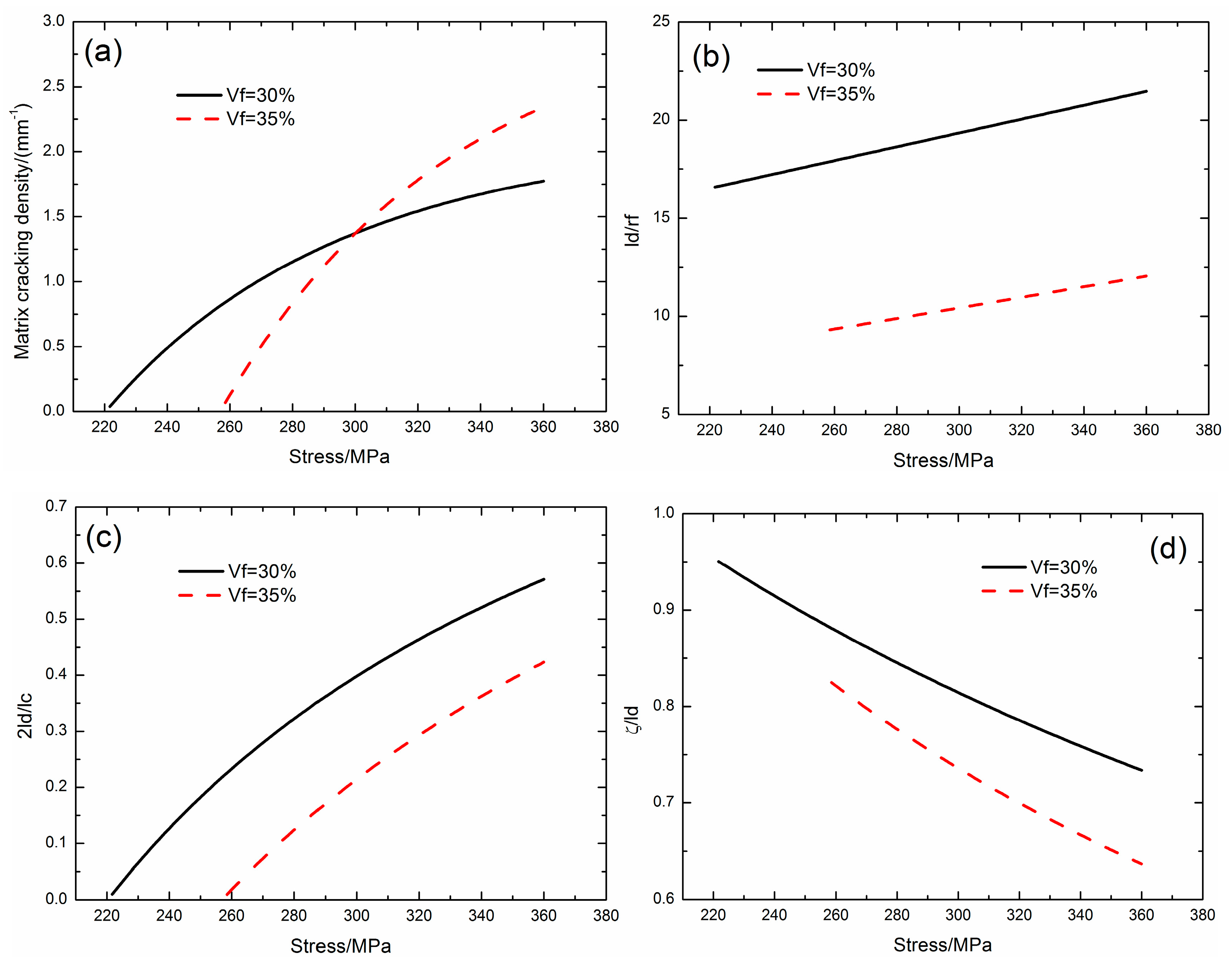
3.1. Effect of Fiber Volume Fraction on Matrix Multiple Fracture and Fiber/Matrix Interface Debonding
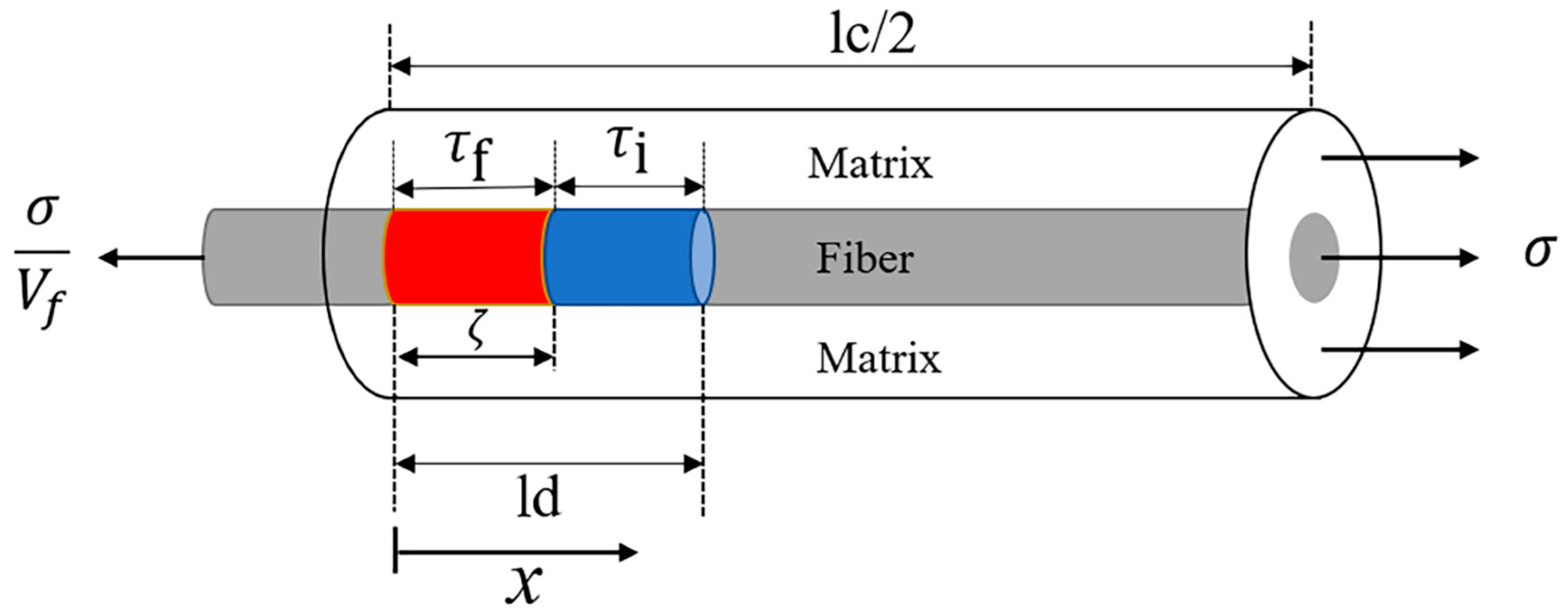
Figure 3 shows the matrix cracking density (
ψ), fiber/matrix interface debonded length (
ld/
rf), the interface debonding ratio (2
ld/
lc), and interface wear ratio (
ζ/
ld) corresponding to different fiber volume contents (i.e.,
Vf = 30% and 35%).
When the fiber volume content is Vf = 30%, the matrix cracking density increases from ψ = 0.04/mm at the first matrix cracking stress of σmc = 221 MPa to ψ = 1.7/mm at the matrix cracking stress of 360 MPa; the fiber/matrix interface debonded length increases from ld/rf = 16.5 to ld/rf = 21.5; the fiber/matrix interface debonding ratio increases from 2ld/lc = 0.9% to 2ld/lc = 57.1%; and, the fiber/matrix interface wear ratio decreases from ζ/ld = 95% to ζ/ld = 73.3%.
When the fiber volume content is Vf = 35%, the matrix cracking density increases from ψ = 0.06/mm at the first matrix cracking stress of σmc = 258 MPa to ψ = 2.3/mm at the matrix cracking stress of 360 MPa; the fiber/matrix interface debonded length increases from ld/rf = 9.3 to ld/rf = 12; the fiber/matrix interface debonding ratio increases from 2ld/lc = 0.9% to 2ld/lc = 42.3%; and, the fiber/matrix interface wear ratio decreases from ζ/ld = 82.4% to ζ/ld = 63.6%.
With the increasing of the fiber volume fraction, the first matrix cracking stress, matrix saturation cracking stress, and matrix cracking density increase; and, the fiber/matrix interface debonded length, fiber/matrix interface debonding ratio, and interface wear ratio decrease. When the fiber volume fraction increases, the stress transfer between the fiber and matrix increases, which increases the matrix strain energy and decreases the matrix crack spacing approaching to the critical matrix strain energy.
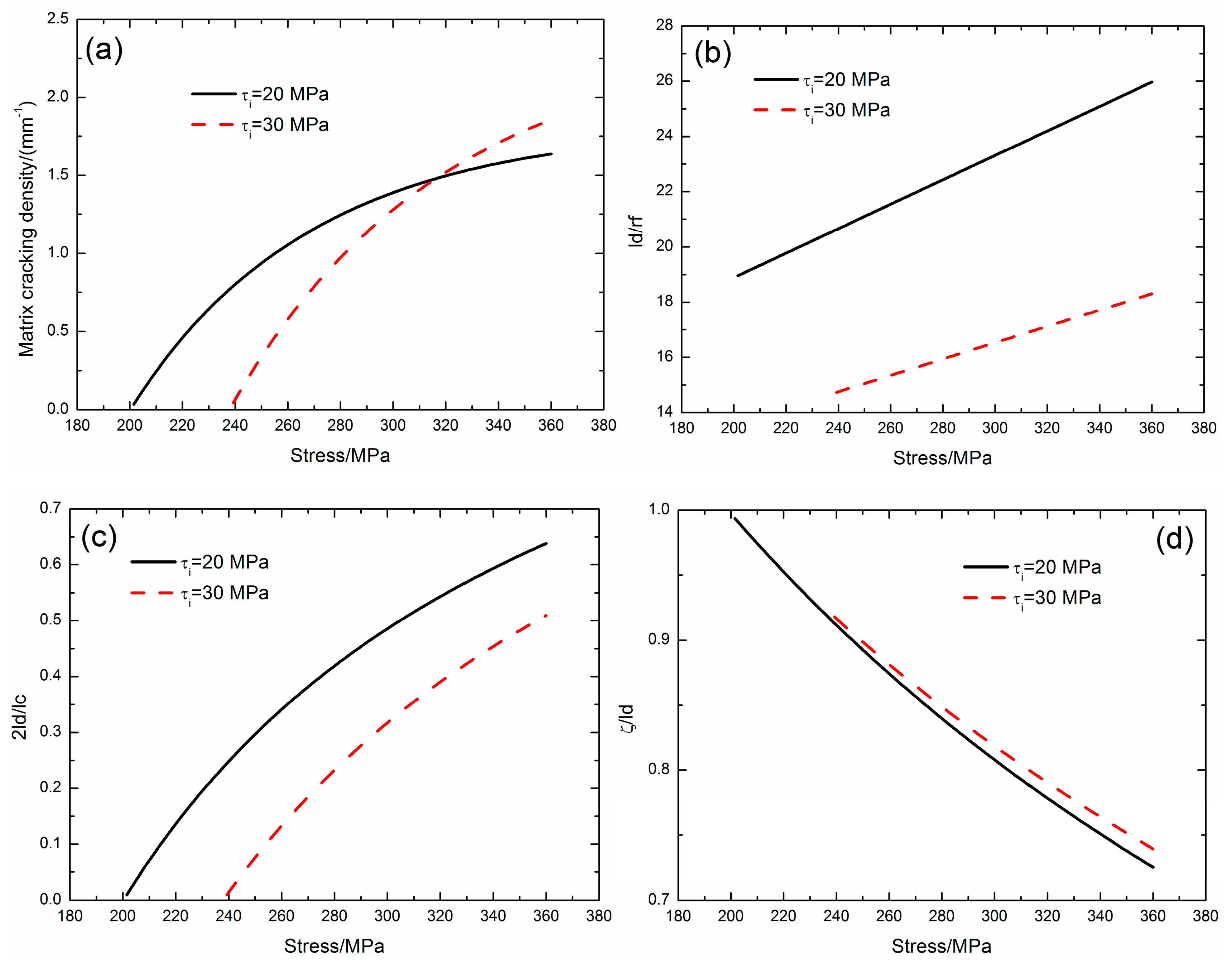
3.2. Effect of Fiber/Matrix Interface Shear Stress on Matrix Multiple Fracture and Fiber/Matrix Interface Debonding
Figure 4 shows the matrix cracking density (
ψ), fiber/matrix interface debonded length (
ld/
rf), fiber/matrix interface debonding ratio (2
ld/
lc), and fiber/matrix interface wear ratio (
ζ/
ld) corresponding to different fiber/matrix interface shear stress (i.e.,
τi = 20 and 30 MPa).
When the fiber/matrix interface shear stress is τi = 20 MPa, the matrix cracking density increases from ψ = 0.03/mm at the first matrix cracking stress of σmc = 201 MPa to ψ = 1.6/mm at the matrix cracking stress of 360 MPa; the fiber/matrix interface debonded length increases from ld/rf = 18.9 to ld/rf = 25.9; the fiber/matrix interface debonding ratio increases from 2ld/lc = 0.9% to 2ld/lc = 63.7%; and, the fiber/matrix interface wear ratio decreases from ζ/ld = 99.3% to ζ/ld = 72.5%.
When the fiber/matrix interface shear stress is τi = 30 MPa, the matrix cracking density increases from ψ = 0.04/mm at the first matrix cracking stress of σmc = 239 MPa to ψ = 1.8/mm at the matrix cracking stress of 360 MPa; the fiber/matrix interface debonded length increases from ld/rf = 14.7 to ld/rf = 18.2; the fiber/matrix interface debonding ratio increases from 2ld/lc = 0.9% to 2ld/lc = 50.9%; and, the fiber/matrix interface wear ratio decreases from ζ/ld = 91.7% to ζ/ld = 73.9%.
With increasing fiber/matrix interface shear stress, the first matrix cracking stress, saturation matrix cracking stress, and matrix cracking density increase; and, the fiber/matrix interface debonded length and interface debonding ratio decrease; and, the fiber/matrix interface wear ratio increases. When the interface shear stress increases, the stress transfer between the fiber and matrix increases, which increases the matrix strain energy and decreases the matrix crack spacing approaching to the critical matrix strain energy.
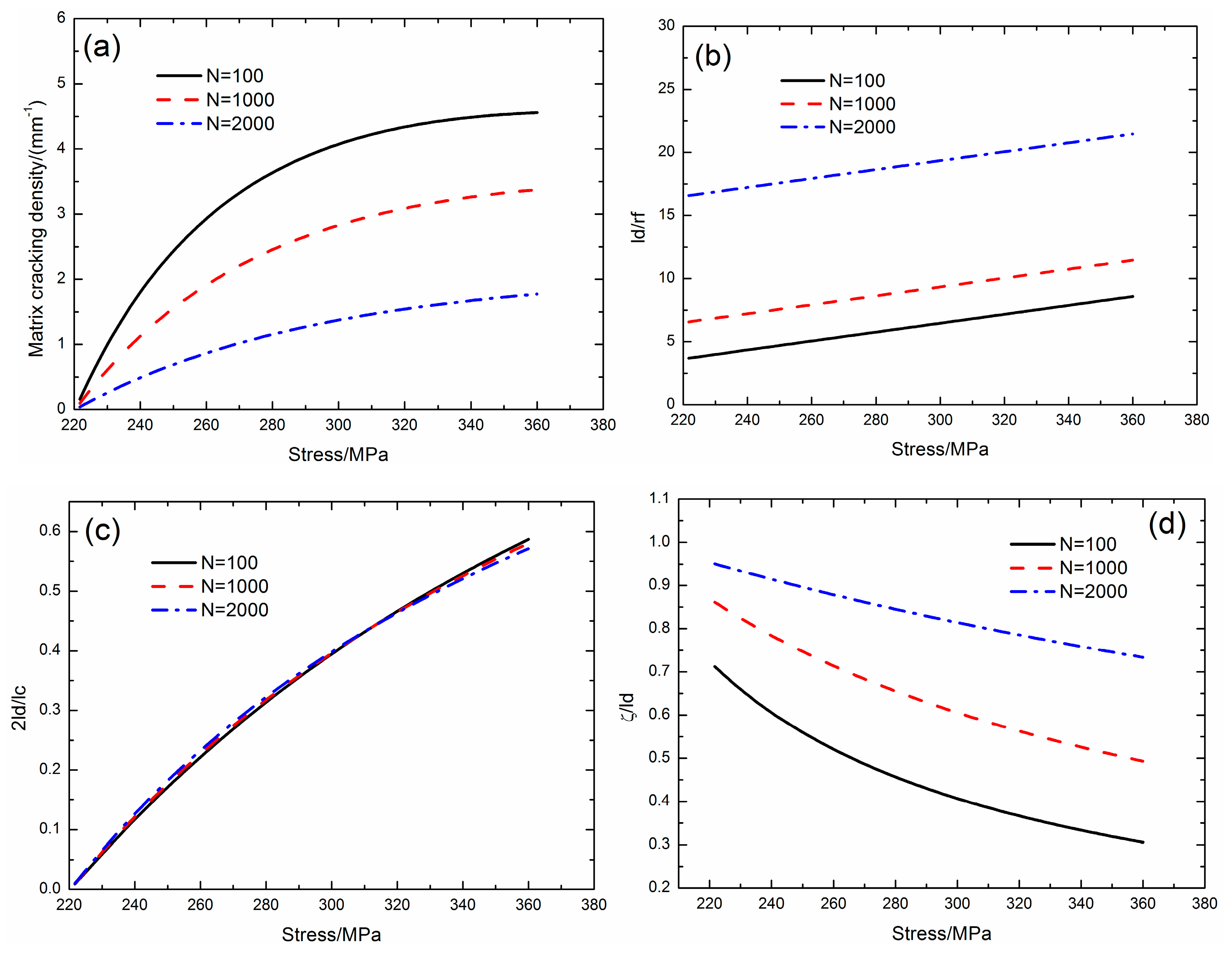
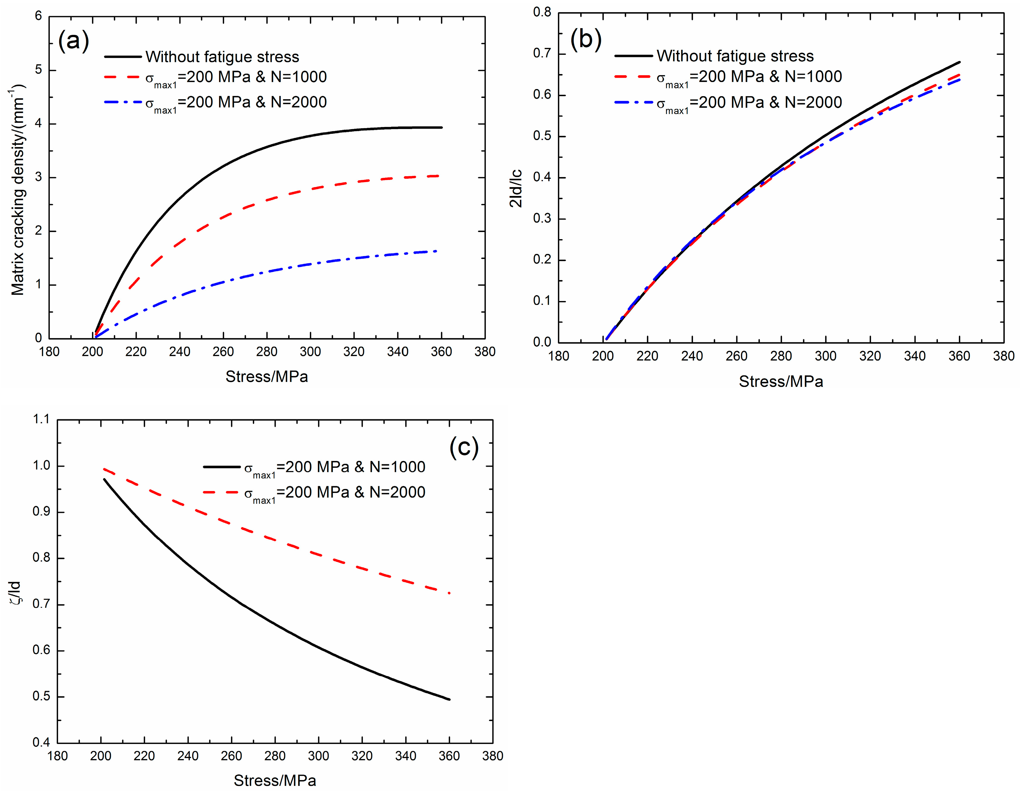
3.3. Effect of Applied Cycle Number on Matrix Multiple Fracture and Interface Debonding
Figure 5 shows the matrix cracking density (
ψ), fiber/matrix interface debonded length (
ld/
rf), fiber/matrix interface debonding ratio (2
ld/
lc), and fiber/matrix interface wear ratio (
ζ/
ld) corresponding to different applied cycles of
N = 100, 1000, and 2000 at the fatigue peak stress of
σmax1 = 200 MPa.
When the applied cycle number is N = 100, the matrix cracking density increases from ψ = 0.16/mm at the first matrix cracking stress of σmc = 221 MPa to ψ = 4.5/mm at the saturation matrix cracking stress of σsat = 360 MPa; the fiber/matrix interface debonded length increases from ld/rf = 3.6 to ld/rf = 8.5; the fiber/matrix interface debonding ratio increases from 2ld/lc = 0.8% to 2ld/lc = 58.6%; and, the fiber/matrix interface wear ratio decreases from ζ/ld = 71.2% to ζ/ld = 30.6%.
When the applied cycle number is N = 1000, the matrix cracking density increases from ψ = 0.09/mm at the first matrix cracking stress of σmc = 221 MPa to ψ = 3.3/mm at the saturation matrix cracking stress of σsat = 360 MPa; the fiber/matrix interface debonding length increases from ld/rf = 6.5 to ld/rf = 11.4; the fiber/matrix interface debonding ratio increases from 2ld/lc = 0.9% to 2ld/lc = 58%; and, the fiber/matrix interface wear ratio decreases from ζ/ld = 86.1% to ζ/ld = 49.3%.
When the applied cycle number is N = 2000, the matrix cracking density increases from ψ = 0.04/mm at the first matrix cracking stress of σmc = 221 MPa to ψ = 1.7/mm at the saturation matrix cracking stress of σsat = 360 MPa; the fiber/matrix interface debonded length increases from ld/rf = 16.5 to ld/rf = 21.4; the fiber/matrix interface debonding ratio increases from 2ld/lc = 0.9% to 2ld/lc = 57.1%; and, the fiber/matrix interface wear ratio decreases from ζ/ld = 95% to ζ/ld = 73.3%.
With increasing the applied cycle number, the interface shear stress decreases, and the matrix cracking density decreases; and the fiber/matrix interface debonded length and interface wear ratio increase. When the applied cycles increase, the interface shear stress decreases, and the stress transfer between the fiber and the matrix also decreases, which leads to the decrease of the matrix strain energy and the increase of the matrix crack spacing approaching to the critical matrix strain energy.
3.4. Comparisons with/without Fatigue Loading
Comparisons of matrix cracking density (
ψ), fiber/matrix interface debonding ratio (2
ld/
lc), and fiber/matrix interface wear ratio with/without cyclic fatigue loading (Case 1,
σmax1 = 200 MPa and
N = 1000; and, Case 2,
σmax1 = 200 MPa and
N = 2000) are shown in
Figure 6.
Without considering cyclic fatigue loading, the matrix cracking density increases from ψ = 0.13/mm at the first matrix cracking stress of σmc = 201 MPa to ψ = 3.9/mm at the saturation matrix cracking stress of σsat = 360 MPa; and, the fiber/matrix interface debonding ratio increases from 2ld/lc = 0.92% to 2ld/lc = 68%.
When considering cyclic fatigue loading for Case 1 (i.e., σmax1 = 200 MPa and N = 1000), the matrix cracking density increases from ψ = 0.08/mm at the first matrix cracking stress of σmc = 201 MPa to ψ = 3.0/mm at the saturation matrix cracking stress of σsat = 360 MPa; the fiber/matrix interface debonding ratio increases from 2ld/lc = 0.94% to 2ld/lc = 64.9%; and, the fiber/matrix interface wear ratio decreases from ζ/ld = 97.1% to ζ/ld = 49.4%. For Case 2 (i.e., σmax1 = 200 MPa and N = 2000), the matrix cracking density increases from ψ = 0.03/mm at the first matrix cracking stress of 201 MPa to ψ = 1.6/mm at the saturation matrix cracking stress of σsat = 360 MPa; the fiber/matrix interface debonding ratio increases from 2ld/lc = 0.99% to 2ld/lc = 63.7%; and, the fiber/matrix interface wear ratio decreases from ζ/ld = 99.3% to ζ/ld = 72.5%.
Under cyclic fatigue loading, the fiber/matrix interface shear stress degrades with applied cycles due to the interface wear. When considering fiber/matrix interface wear, the matrix cracking density and the fiber/matrix interface debonding ratio decrease.
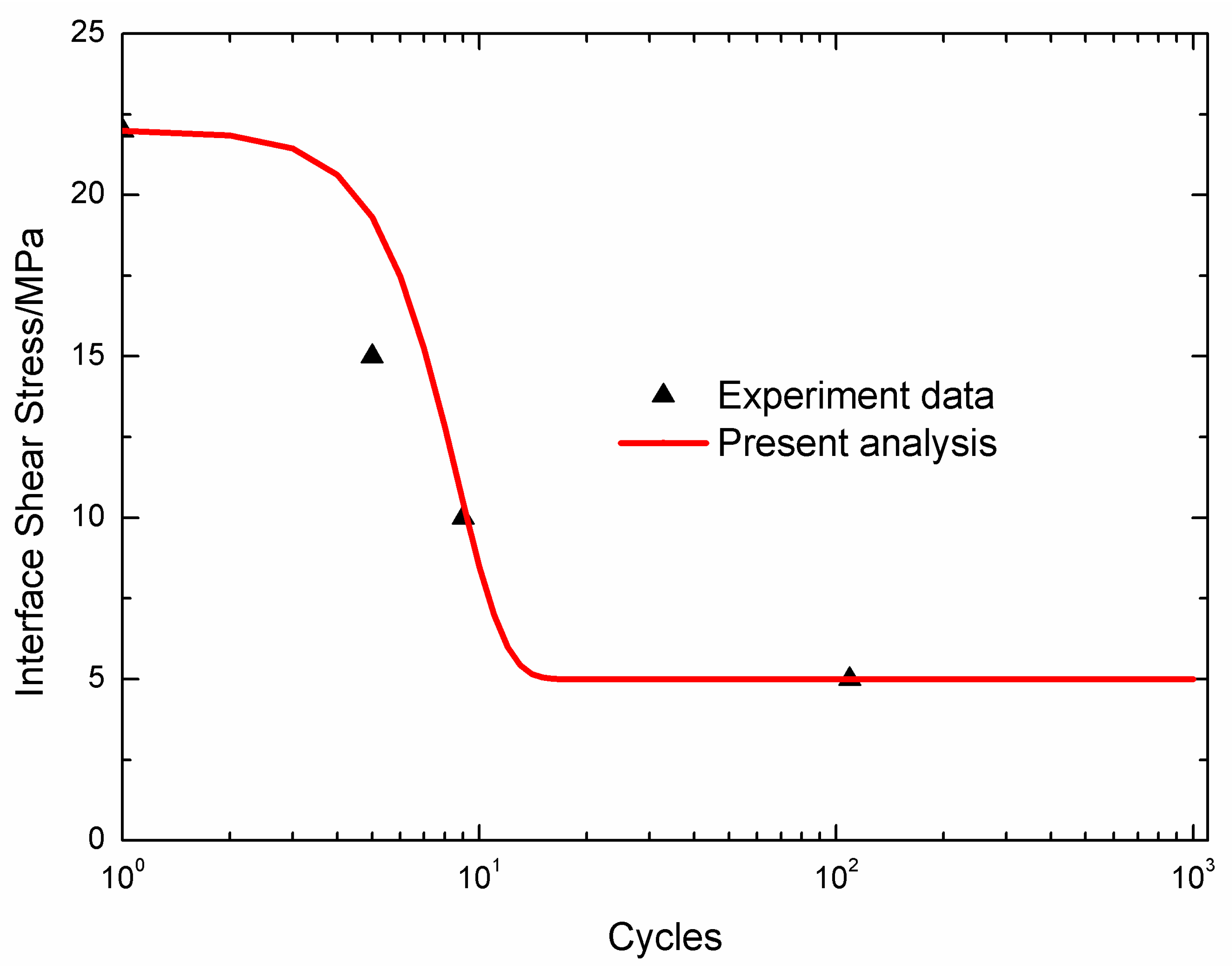
4. Experimental Comparisons
The experimental and theoretical matrix cracking density (
ψ), fiber/matrix interface debonded ratio (2
ld/
lc), and fiber/matrix interface wear ratio (
ζ/
ld) versus the applied stress for different fiber-reinforced CMCs, i.e., unidirectional SiC/CAS-II [
33], SiC/SiC [
34], SiC/CAS [
35], SiC/Borosilicate [
36], and mini-SiC/SiC [
37] composites are predicted, as shown in
Figure 7,
Figure 8,
Figure 9,
Figure 10 and
Figure 11.
Table 1 lists the material properties of fiber-reinforced CMCs. The parameters of
ω and
λ listed in
Table 1 are identified using the present approach.
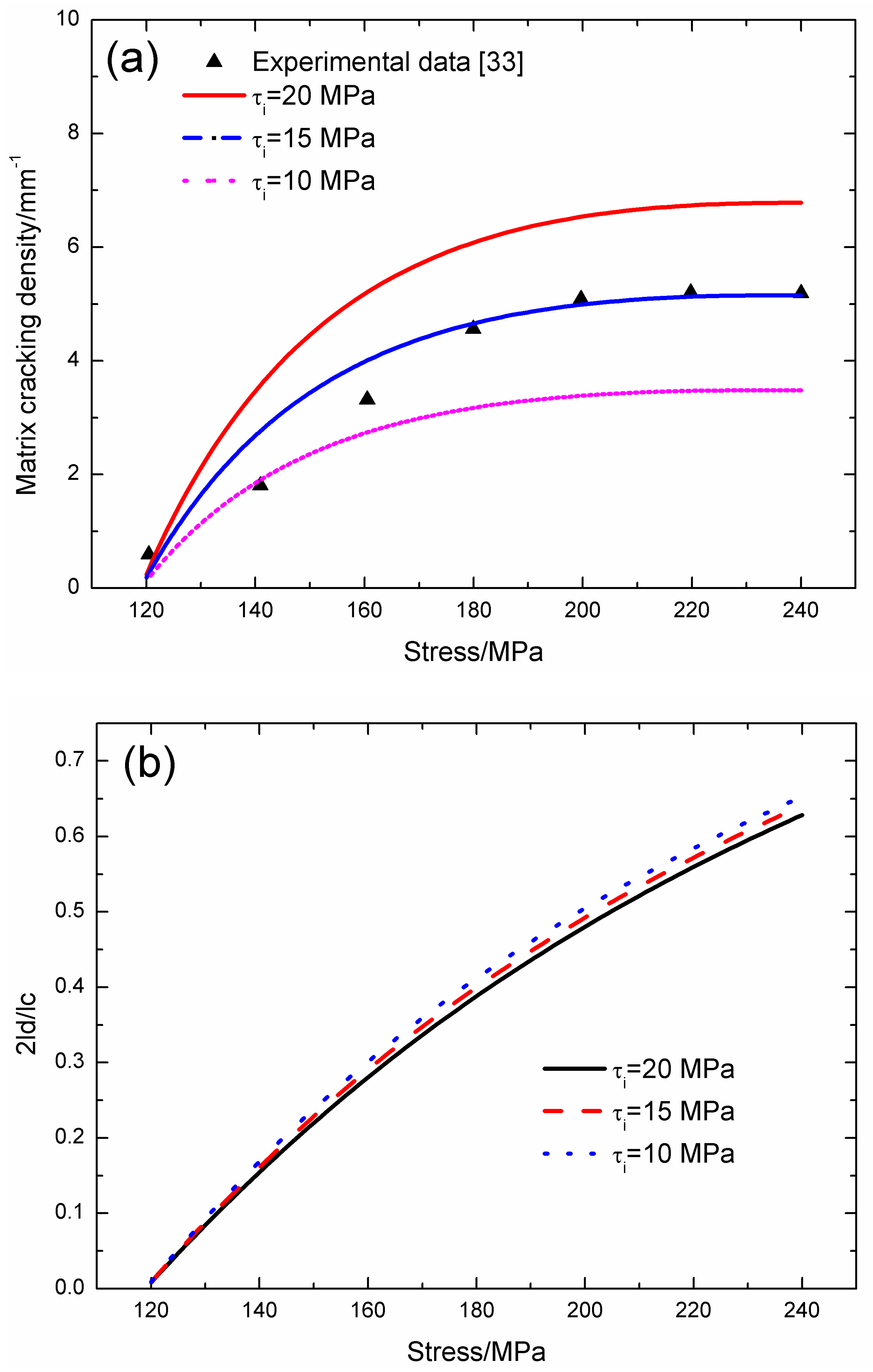
Holmes and Cho [
33] investigated the fatigue behavior of unidirectional SiC/CAS-II composite at room temperature. The fatigue tests were periodically interrupted to obtain the surface replicas of matrix crack spacing, and a stress of 10 MPa was maintained on the specimen while taking the replicas. The fatigue loading frequency was
f = 25 Hz and the specimen was cycled for 25,000 cycles at different fatigue peak stresses of
σmax = 120, 140, 160, 180, 200, 220, and 240 MPa. Under cyclic fatigue loading, the fiber/matrix interface shear stress degrades with applied cycles, and the initial fiber/matrix interface shear stress is
τi = 20 MPa.
Figure 7 shows the experimental and predicted matrix cracking density and the fiber/matrix interface debonding versus the applies stress curves. The predicted matrix cracking density with the initial interface shear stress of
τi = 20 MPa is much higher than the experimental data; however, the predicted matrix cracking density with low interface shear stress of
τi = 15 MPa agrees with the experimental data, which is mainly due to the interface wear mechanism.
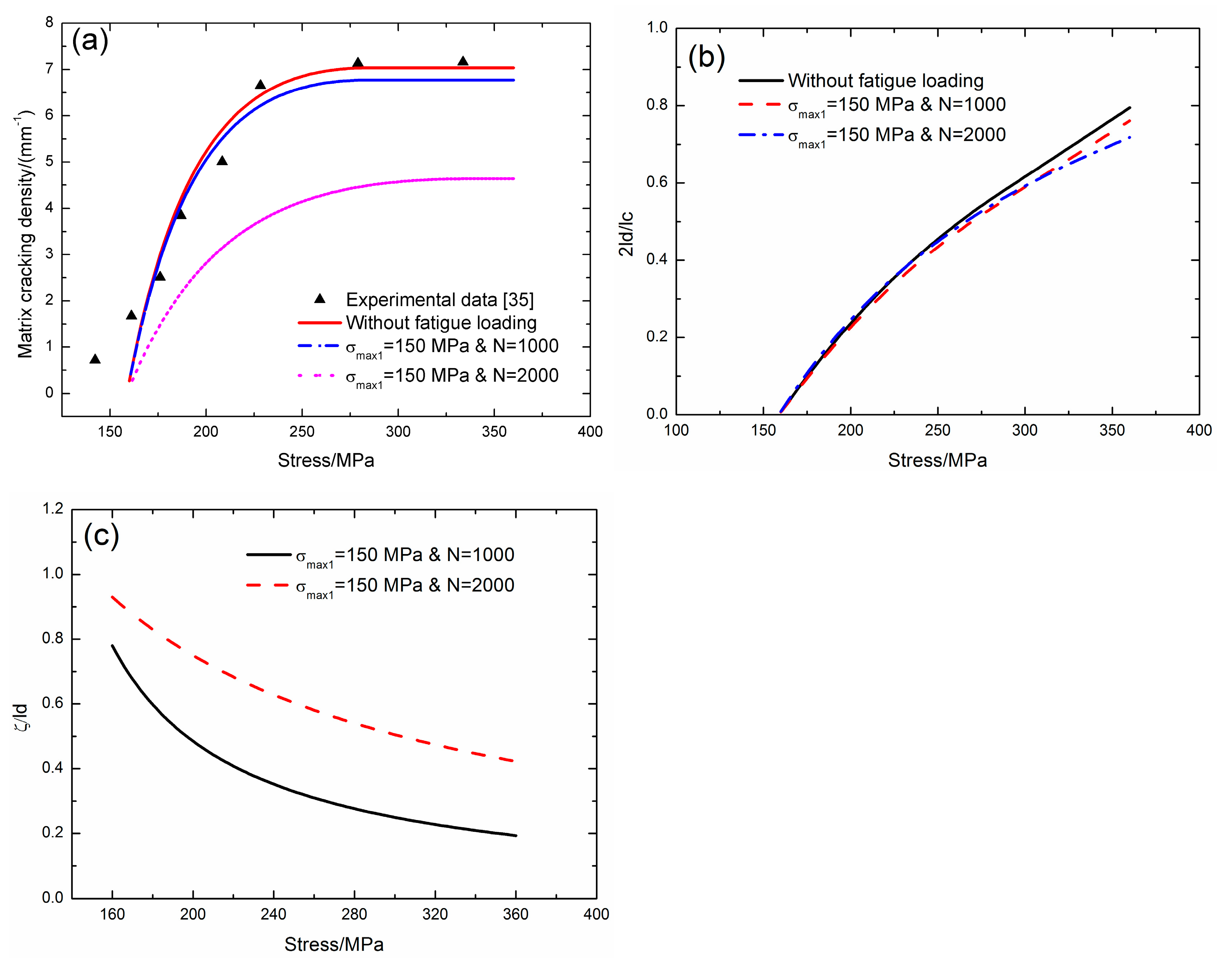
Pryce and Smith [
35] investigated the tensile behavior of unidirectional SiC/CAS composite at room temperature. The quasi-static tests were carried out using an Instron 1175 under displacement control at a cross-head speed of 0.05mm/min. The direct observations of matrix cracking were made using optical and scanning electron microscopy of the polished coupon edges. The matrix cracking density was determined by counting the number of cracks in a gauge-length of about 15mm. For the unidirectional SiC/CAS composite without cyclic fatigue loading, the matrix cracking starts from the applied stress of
σmc = 160 MPa and it approaches saturation at the applied stress of
σsat = 288 MPa; the matrix cracking density determined by Equation (22) increases from
ψ = 0.2/mm to the saturation value of
ψ = 7.0/mm; and, the fiber/matrix interface debonded ratio that is determined by Equation (13) increases from 2
ld/
lc = 0.7% at 160 MPa to 2
ld/
lc = 79% at 360 MPa. Under cyclic fatigue loading of
σmax1 = 150 MPa and
N = 1000, the matrix cracking density that is determined by Equation (22) increases from
ψ = 0.26/mm at
σmc = 160 MPa to
ψ = 6.7/mm at
σsat = 284 MPa; the fiber/matrix interface debonding ratio that is determined by Equation (13) increases from 2
ld/
lc = 0.7% at 160 MPa to 2
ld/
lc = 76.1% at 360 MPa; and, the fiber/matrix interface wear ratio decreases from
ζ/
ld = 77.9% at 160 MPa to
ζ/
ld = 19.3% at 360 MPa. Under cyclic fatigue loading of
σmax1 = 150 MPa and
N = 2000, the matrix cracking density that is determined by Equation (22) increases from
ψ = 0.12/mm at
σmc = 160 MPa to
ψ = 4.6/mm at
σsat = 310 MPa; the fiber/matrix interface debonding ratio that is determined by Equation (13) increases from 2
ld/
lc = 0.8% at 160 MPa to 2
ld/
lc = 71.8% at 360 MPa; and, the fiber/matrix interface wear ratio decreases from
ζ/
ld = 92.9% at 160 MPa to
ζ/
ld = 42.2% at 360 MPa, as shown in
Figure 8.
Domergue et al. [
34] investigated the damage and failure of unidirectional SiC/SiC composite at room temperature. The tensile tests were conducted with periodic unload/reload cycles, and the matrix cracking density was determined from line scans. For the unidirectional SiC/SiC composite without cyclic fatigue loading, the matrix cracking starts from the applied stress of
σmc = 240 MPa and it approaches saturation at the applied stress of
σsat = 320 MPa; the matrix cracking density that is determined by Equation (22) increases from
ψ = 1.1/mm to the saturation value of
ψ = 13/mm. Under the cyclic fatigue loading of
σmax1 = 200 MPa and
N = 1000, the matrix cracking density that is determined by Equation (22) increases from
ψ = 0.21/mm at
σmc = 240 MPa to
ψ = 5.6/mm at
σsat = 320 MPa; the fiber/matrix interface debonded length that is determined by Equation (13) increases from
ld/
rf = 2.8 at 240 MPa to
ld/
rf = 4.2 at 320 MPa; and, the fiber/matrix interface wear ratio decreases from
ζ/
ld = 72.8% at 240 MPa to
ζ/
ld = 48.9% at 320 MPa. Under cyclic fatigue loading of
σmax1 = 200 MPa and
N = 2000, the matrix cracking density that is determined by Equation (22) increases from
ψ = 0.09/mm at
σmc = 240 MPa to
ψ = 2.8/mm at
σsat = 320 MPa; the fiber/matrix interface debonded length that is determined by Equation (13) increases from
ld/
rf = 7.0 at 240 MPa to
ld/
rf = 8.4 at 320 MPa; and, the fiber/matrix interface wear ratio decreases from
ζ/
ld = 89.8% at 240 MPa to
ζ/
ld = 75% at 320 MPa, as shown in
Figure 9.
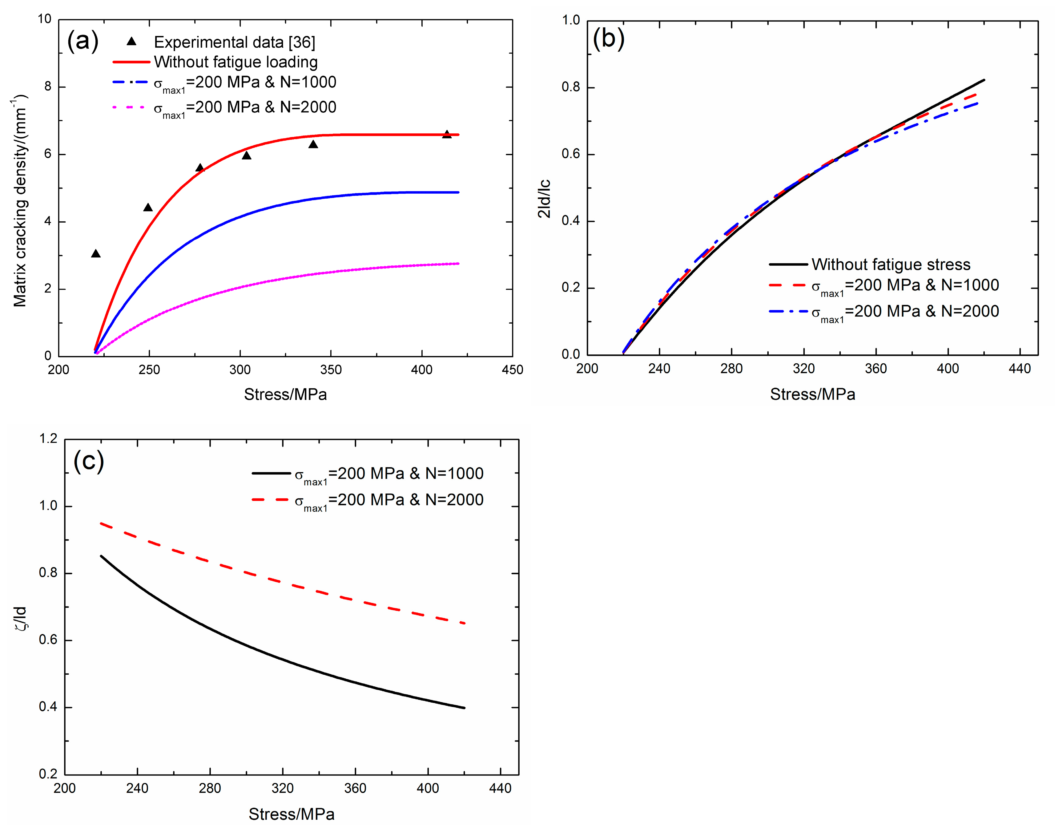
Okabe et al. [
36] investigated the tensile behavior of unidirectional SiC/Borosilicate composite at room temperature. The tensile tests were performed at a constant cross-head speed of 0.4 mm/min. The specimens were periodically stopped under tensile to replicate the matrix cracking density on the specimen surfaces using polyacetate films. For the unidirectional SiC/Borosilicate composite without cyclic fatigue loading, the matrix cracking starts from the applied stress of
σmc = 220 MPa and it approaches saturation at the applied stress of
σsat = 360 MPa; the matrix cracking density that is determined by Equation (22) increases from
ψ = 0.2/mm to the saturation value of
ψ = 6.5/mm; and, the fiber/matrix interface debonded ratio that is determined by Equation (13) increases from 2
ld/
lc = 0.8% at 220 MPa to 2
ld/
lc = 82% at 420 MPa. Under cyclic fatigue loading of
σmax1 = 200 MPa and
N = 1000, the matrix cracking density that was determined by Eq. (22) increases from
ψ = 0.12/mm at
σmc = 220 MPa to
ψ = 4.8/mm at
σsat = 402 MPa; the fiber/matrix interface debonding ratio that is determined by Equation (13) increases from 2
ld/
lc = 0.9% at 220 MPa to 2
ld/
lc = 78.9% at 420 MPa; and, the fiber/matrix interface wear ratio decreases from
ζ/
ld = 85.2% at 220 MPa to
ζ/
ld = 39.8% at 420 MPa. Under cyclic fatigue loading of
σmax1 = 200 MPa and
N = 2000, the matrix cracking density that is determined by Equation (22) increases from
ψ = 0.05/mm at
σmc = 220 MPa to
ψ = 2.7/mm at
σsat = 420 MPa; the fiber/matrix interface debonding ratio as determined by Equation (13) increases from 2
ld/
lc = 0.9% at 220 MPa to 2
ld/
lc = 75.9% at 420 MPa; and, the fiber/matrix interface wear ratio decreases from
ζ/
ld = 94.9% at 220 MPa to
ζ/
ld = 65.1% at 420 MPa, as shown in
Figure 10.
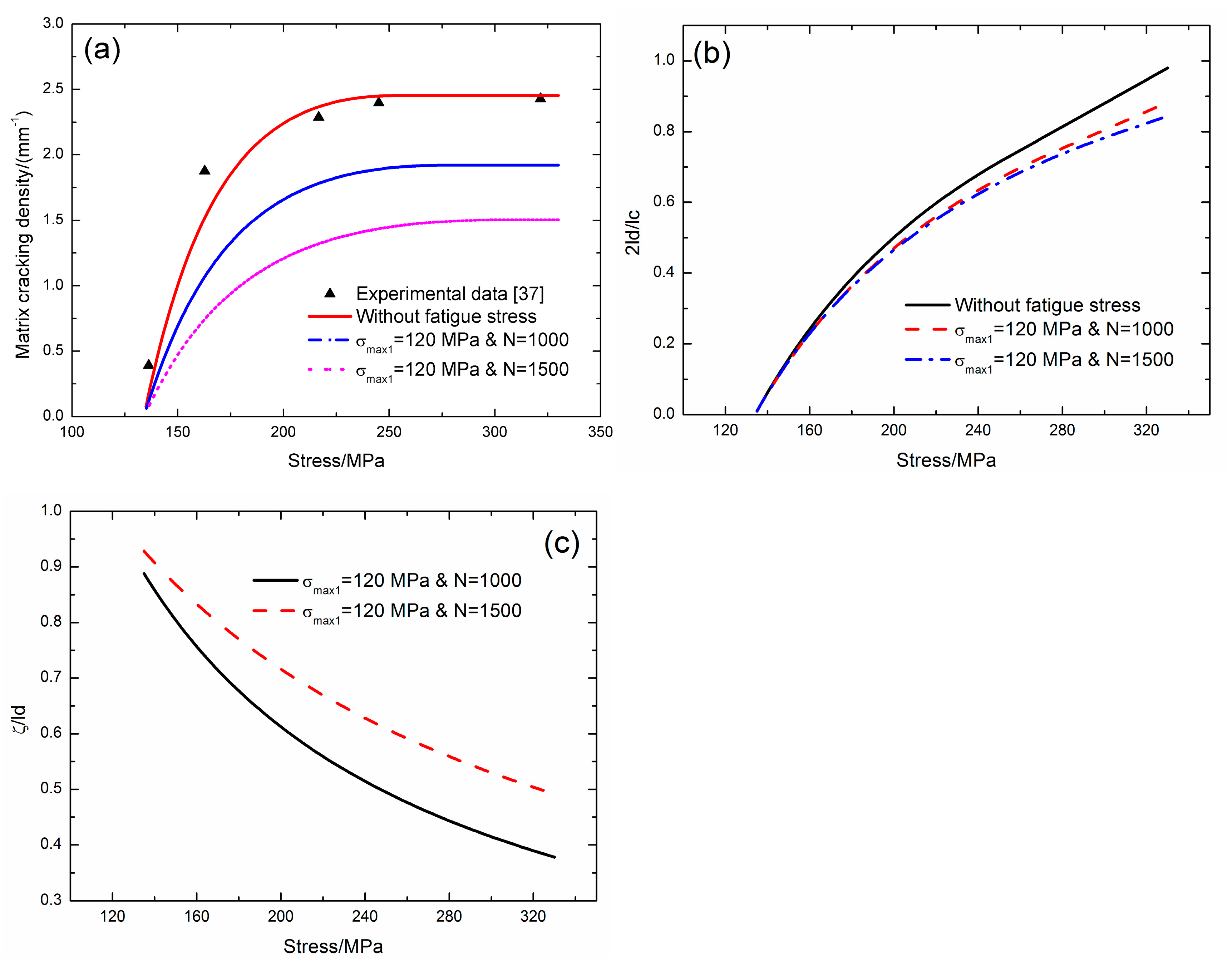
Zhang et al. [
37] investigated the tensile damage of mini-SiC/SiC composite at room temperature. Real-time matrix crack detection of a digital microscope obtained the matrix cracking density. For the mini-SiC/SiC composite without cyclic fatigue loading, the matrix cracking starts from the applied stress of
σmc = 135 MPa and it approaches saturation at the applied stress of
σsat = 250 MPa; the matrix cracking density that was determined by Equation (22) increases from
ψ = 0.4/mm to the saturation value of
ψ = 2.4/mm; and, the fiber/matrix interface debonded ratio that is determined by Equation (13) increases from 2
ld/
lc = 1.0% at 135 MPa to 2
ld/
lc = 98% at 330 MPa. Under cyclic fatigue loading of
σmax1 = 120 MPa and
N = 1000, the matrix cracking density that is determined by Equation (22) increases from
ψ = 0.05/mm at
σmc = 135 MPa to
ψ = 1.9/mm at
σsat = 277 MPa; the fiber/matrix interface debonding ratio as determined by Equation (13) increases from 2
ld/
lc = 1.0% at 135 MPa to 2
ld/
lc = 88.2% at 330 MPa; and, the fiber/matrix interface wear ratio decreases from
ζ/
ld = 88.8% at 135 MPa to
ζ/
ld = 37.7% at 330 MPa, as shown in
Figure 11.


