Communication

Ice-Templated Geopolymer—Fe/Mn Oxide Composites Conceived as Oxygen Carriers

National Research Council of Italy, Institute of Science and Technology for Ceramics (CNR-ISTEC), Via Granarolo 64, 48018 Faenza, RA, Italy
*
Author to whom correspondence should be addressed.
Ceramics 2019, 2(1), 148-160; https://doi.org/10.3390/ceramics2010014
Submission received: 28 January 2019 / Revised: 15 February 2019 / Accepted: 25 February 2019 / Published: 1 March 2019
(This article belongs to the Special Issue Ice-Templated and Freeze-Cast Ceramics)

Abstract

:
Ice-templating (freeze-casting) technique was applied to a novel class of geopolymer composites containing Fe/Mn oxides, previously tested and reported in others works as synthetic oxygen carriers for chemical looping combustion (CLC), in order to obtain composite monoliths with lamellar macro-porosities by unidirectional freezing of water-based sol-gel systems. Geopolymer-Fe/Mn oxides composites carriers were also produced as beads, suitable for fixed bed reactors, by an injection-solidification method in liquid nitrogen. After conditioning at 900 °C, the temperature needed for CLC applications, the composite beads and monoliths possess similar total porosity % and total pore volume, being ≈65% and 570 mm3 g−1, respectively, as well as a specific surface area of around 2.4–2.9 m2/g.

1. Introduction

Geopolymers are commonly obtained at low temperatures (under 100 °C) by the mixing of an aluminosilicate source material with an alkali hydroxide or alkali silicate solution [1]. The final amorphous network consists of an alternating sequence of tetrahedral [SiO4] and [AlO4], and the microstructure is composed of nanoparticulates separated by micro- and mesopores [2,3].
The geopolymer matrix, formed by nanoprecipitates that act as a “glue”, can be easily mixed with several fillers in order to produce composite materials suitable for different applications.
The production of composites is indeed of considerable importance to further increase the potentialities of geopolymers. In this respect, geopolymer composites have been already formulated to obtain oxygen carriers suitable for chemical looping combustion (CLC) processes [4,5] or catalysts for tar decomposition [6]. CLC is currently considered one of the best alternatives to reduce the economic cost of CO2 capture. This technology is based on indirect fuel combustion by use of a solid oxygen carrier, generally a metal oxide having the capability of transporting the oxygen needed for the combustion from an air reactor to a fuel reactor, usually designed as two coupled fluidized beds [7]. The combustion takes place in the fuel reactor through the reaction between the fuel and the solid oxygen carrier, which is consequently reduced to a lower oxidation state. The reduced oxygen carrier is then transferred to the air reactor, where it is regenerated by oxidation in air at high temperature [8].
For this purpose, geopolymer matrices were doped with iron, manganese oxides, or a mix of the two, as these metal oxides facilitate the active phases necessary for the process. Indeed, in such composite materials, the active phase was tightly embedded into the geopolymer matrix, endowing the material with the required stability. The production of these materials was aimed at overcoming the major limitations in the production of the oxygen carriers, which normally requires costly or complex processing routes. Oxygen carriers are usually obtained by traditional methods, such as the impregnation of supports with metal salts followed by drying and calcination [9], or the use of ceramic synthesis, which involves the optimization of a slurry and the subsequent shaping, granulation, drying, and final sintering at high temperature. The unique, one-step production process adopted for the production of the geopolymer carriers results particularly advantageous for time and cost optimization of the entire synthesis, especially in the perspective of large-scale applications, which are heavily affected by cost of materials and by energy demand of the process.
Taking into account that potential oxygen carriers should have a series of requirements, such as high oxygen transport capacity, negligible decline in the performance after repeated cycles, resistance to comminution and agglomeration, large availability and low cost [8], and an appropriate porosity to support the mentioned requirements, in the present paper new methods to obtain carriers for packed beds were explored. One of the major advantages of geopolymers is the easy, low-cost, and green production process, and the ease of shaping the final materials [1]. Since geopolymerization is a water-based reaction, it is possible to obtain a custom-tailored porosity. Water content in the starting mixture affects the intrinsic mesoporosity of the geopolymer matrix, since water acts as a pore former during the polycondensation stage [3]. Furthermore, a lamellar macroporosity can be obtained using an ice-templating technique, as already reported [10,11].
The ice-templating technique consists of freezing an aqueous suspension, followed by ice sublimation under reduced pressure. The resulting green body is generally sintered to consolidate the overall architecture, as well as to obtain the desired mechanical and functional properties, while maintaining a high level of porosity.
Unidirectional channel-like (lamellar) porosity is obtained in the case of unidirectional freezing, where pores are the replica of ice crystals [12,13,14].
The process is environmentally friendly, since it uses water as a removable template, is highly versatile, and the resulting structures are highly tunable by changing the process conditions. Indeed, the ice-template can be easily removed through simple thawing and drying, overcoming the problems related to other templating techniques, which require the use of expensive templates, removed through either high temperature or extremely high or low pH conditions [15].
The authors have already reported on the application of this technique to a water-based sol-gel system able to obtain metakaolin-based geopolymers, avoiding the use of dispersant and binders and a consolidation at high temperature [10,11].
The aim of the present work is to extend the use of this technique to the novel geopolymer-Fe/Mn oxides composites, in order to obtain oxygen carriers with specific geometries and porosity for CLC processes conceived with a packed bed configuration.
In fact, the composites were originally conceived and tested as oxygen carriers for CLC processes designed to be used in the form of granules for a fluidized bed configuration.
However, other reactor concepts could be proposed for CLC as twin packed bed reactors. The main advantages of packed bed reactor technology for CLC is that the separation of the gas and particles is intrinsically avoided, the particles are not comminuted small enough, and the pressure drop is limited. Thus, packed bed CLC shows great potential as an alternative for the interconnected fluidized bed system [16].
As a matter of fact, ice-templating allowed obtainment of composite monoliths with oriented, lamellar macroporosity, as well as millimeter-sized beads with radial porosity, obtained through an injection-solidification method directly in liquid nitrogen. The formation of micrometer sized pores would favor the easy diffusion of bulky molecules inside the shaped beads [17] in fixed bed reactors.
Starting from the already tested composite mixture based on a metakaolin-based geopolymer matrix added with a mix of Fe and Mn oxides [6], the geopolymerization was triggered following the optimized process of freeze-casting reported by the authors [10]. The slurry has been used to produce both monoliths and beads, then the obtained materials have been characterized in terms of macro- and microstructure, porosity, and specific surface area.

2. Materials and Methods

2.1. Materials and Sample Preparation

The geopolymer matrix was prepared mixing metakaolin grade M1200S purchased from Imerys (ssa = 25 m2 g−1, d50 = 1.5 µm) with a solution of potassium di-silicate used as alkali activator, having a molar ratio of SiO2:K2O = 2 and H2O:K2O = 13.5. The solution was prepared by dissolving KOH pellets (purity >85% from Sigma-Aldrich) in distilled water and adding fumed silica powder (99.8% from Sigma-Aldrich) under magnetic stirring.
The geopolymer slurry, with a theoretical Si:Al molar ratio equal to 2, was prepared using a planetary centrifugal mixer (Thinky Mixer ARE-500, Thinky, Japan) for 3 minutes at 900 rpm.
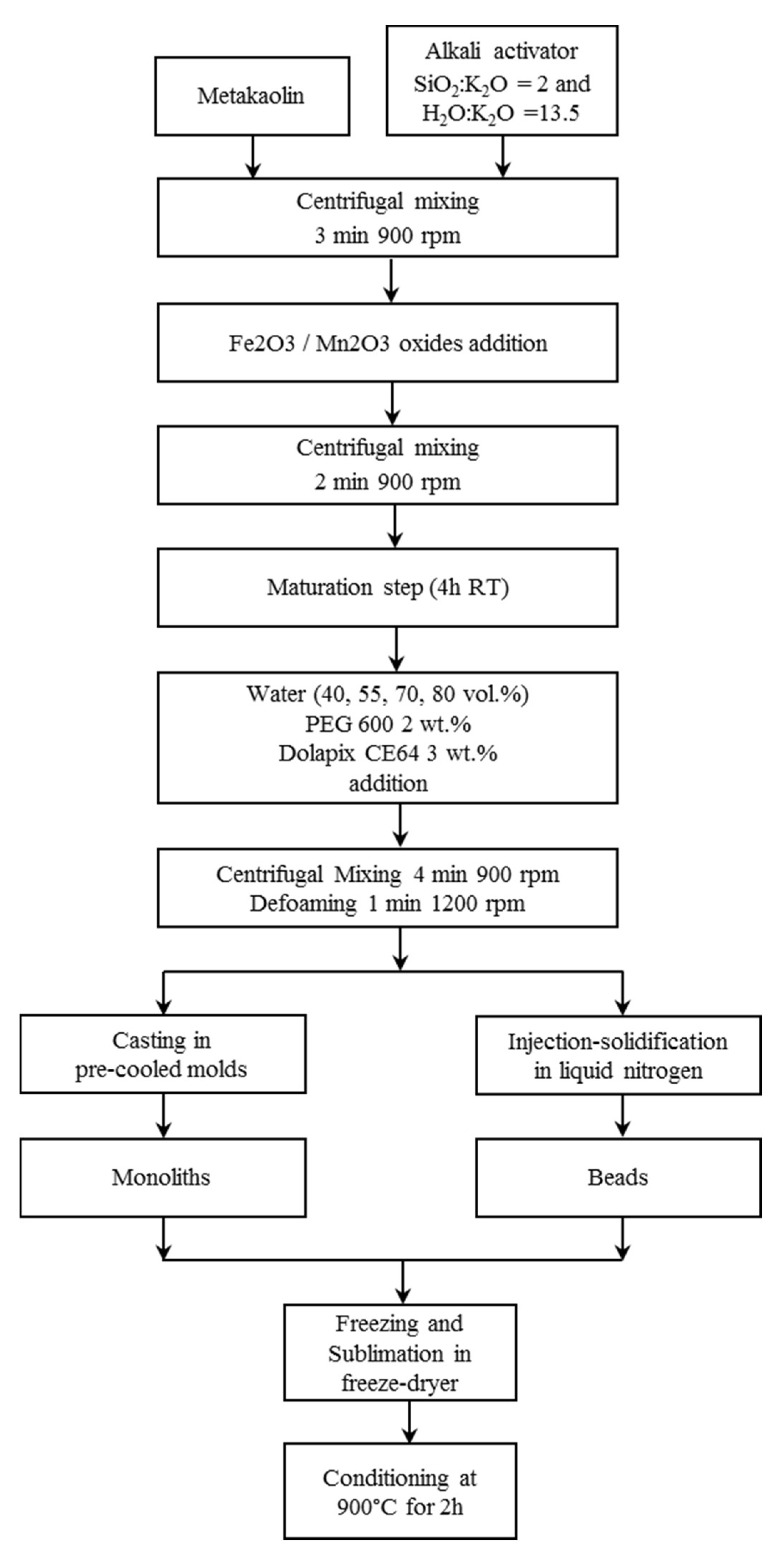
Then the metal oxides were added in equal amount to the geopolymer mixture to the extent of 51% by weight of dry solid geopolymer reactants. Mn2O3 (Sigma-Aldrich) and Fe2O3 (MRC, Toulouse, France) 325 mesh powders were used and mixed with the centrifugal mixer for 2 minutes at 900 rpm. After the preparation, the composite slurries underwent a maturation step of 4 h at room temperature, already reported in [10], in order to trigger the geopolymerization, but avoiding the complete consolidation of the slurry. Deionized water was then added to the maturated slurry in different amounts (40, 55, 70, 80 vol.%), calculated over the theoretical volume of the geopolymer solid matrix. Dispersant Dolapix CE64 (Zschimmer and Schwarz, Lahnstein, Germany) and binder Polyethylene glycol (PEG 600, Merck, Kenilworth, NJ, USA) were also added in the amount of 3 and 2 wt.% on the dry solid composite, respectively. The mixture was then mixed with the centrifugal mixer for 4 minutes at 900 rpm and a defoaming step (1 minute at 1200 rpm) was lastly added.
The prepared mixture was then cast in cylindrical plastic molds, which have been pre-cooled on the freeze dryer shelf at −40 °C, to produce monoliths with a diameter of 15 mm and a height of 16 mm. Cast slurries were frozen at −40 °C and the solidified phase was then sublimated at 10 Pa for 24 h, using a freeze-drier apparatus (Edwards Mod. MFD01, Crawley, UK). Conversely, to produce the beads, the mixture was directly dripped in a liquid N2 bath using a peristaltic pump (speed 3 rpm) with a nozzle of 0.6 mm diameter, obtaining ≈2–3 mm sized beads. The beads were then sublimated at 10 Pa for 24 h (Edwards Mod. MFD01, Crawley, UK).
Finally, the monoliths and the beads underwent a thermal treatment in a muffle furnace at 900 °C for 2 h in air, as a conditioning step in accordance to CLC process [4,5].
A flow-chart of the freeze-casting process used to produce monoliths and beads is reported in Figure 1 and the compositions and codes of the produced samples are reported in Table 1.

2.2. Characterization

The morphological and macrostructural features of the ice-templated samples were investigated by digital microscopy (3D Digital Microscope RH2000, Hirox, Japan).
The microstructural features of the composite monoliths and beads were examined by Environmental Scanning Electron Microscopy (E-SEM FEI Quanta 200, FEI Company, Hillsboro, OR, USA) and by Field Emission Gun-Scanning Electron Microscopy (FEG-SEM, ΣIGMA: Zeiss, Germany) equipped with EDS (probe X-Act, INCA Energy 300, Oxford Instruments, Abingdon, UK) used for element mapping. The samples before the observation were coated with a thin layer of gold using a turbo-pumped sputter coater (Quorum Q150T ES, Quorum Technologies Ltd., East Sussex, UK).
The percent values of sample total porosity were calculated according to the Equation (1):
Total porosity (%) = [1 − (bulk density/true density)] × 100
The bulk density of samples was determined by weight-to-volume ratio. The volume was geometrically measured by using a caliper (accuracy ± 0.05 mm). The true density, i.e., mass/volume of the solid, was determined by helium pycnometry (Multivolume pycnometer 1305 by Micrometrics).
The pore size distribution in the range 0.0058–100 µm was analyzed by mercury intrusion porosimetry (MIP, surface tension = 0.48 N/m and contact angle = 140°, Thermo Finnigan Pascal 140 and Thermo Finnigan Pascal 240), with an experimental error of 4% due to the accuracy of the instrument.
The measurements of specific surface area were conducted using a Thermo ScientificTM Surfer instrument and the specific surface area (SBET) was calculated by the Brunauer–Emmet–Teller method by means of nitrogen adsorption at 77 K. The measurements were performed on monolith pieces and on the entire beads.

3. Results and Discussion

3.1. Macro- and Microstructural Characterization: Monoliths

Ice-template composite monoliths of 15 mm diameter and 16 mm height were obtained after the freeze-casting process. After the conditioning treatment at 900 °C, an anisotropic contraction (2–4% diameter; 3–5% height) occurred because of partial densification, due to sintering for viscous flow [4]. In Figure 2 the picture of the produced monoliths is reported. Monoliths show a different macrostructure depending on the amount of additional water (vol.%) targeted for the ice-templating process. Indeed, the water amount in the starting mixture is crucial for the lamellae formation [14], since the ice-templating process involved a segregation-induced templating of a second phase. For this process the second phase is constituted by the reacting geopolymer particles embedding the Fe/Mn oxides, while water is the solidifying liquid medium which is then removed by sublimation to create the final porosity.
In general, an increase of the H2O vol.% used for the ice-templating led to a decrease of the bulk density and to an increase of the total porosity % (Table 1).
MnFe40M samples had the highest solid loading, possessing the lowest H2O content (40 vol.%) available for ice-templating. As a result, the lamellar macro-structure barely developed because of the entrapment of geopolymer particles within the growing ice crystals and the fast freezing of the liquid medium (Figure 2a). With the increase of the H2O vol.% the formation of the typical lamellar macrostructure on the top of the sample and along the longitudinal axes was favored. However, a water content that was too high, as in samples MnFe70M and MnFe80M, led to separation and sedimentation of the mixture during the freezing process.
Monoliths showed the formation of a white layer on the top, due to the migration of the silicate, and a dark layer on the bottom, due to sedimentation of the heavier Fe/Mn oxides particles. In sample MnFe70M (Figure 2c) a thinner white layer was visible, while it was particularly evident and cracked on the top surface of sample MnFe80M (Figure 2d), where the sedimentation of the oxides in a dark layer on the bottom was also observed.
Conversely, an intermediate value of water (55 vol.%), as in sample MnFe55M and as already observed for the ice-templated metakaolin-based geopolymer [10], allowed the formation of a well-developed lamellar macrostructure with the formation of an homogeneous monolith without sedimentation problems (Figure 2b). Therefore, the slurry used for MnFe55M resulted as being the most suitable for the process, and the monoliths obtained were selected and further characterized.
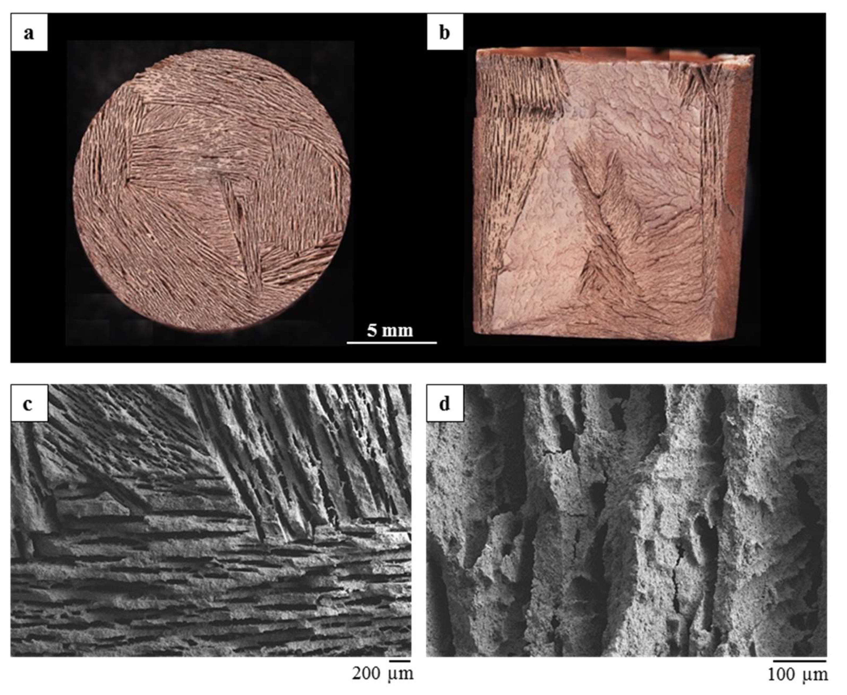
The well-developed lamellar macrostructure of MnFe55M was particularly evident in the image obtained by optical microscopy, which reports the top surface (Figure 3a) and the cross section of the monolith (Figure 3b). The top surface (Figure 3a) showed the formation of parallel lamellae, assembled in domains characterized by different orientations and width of the lamellae in the plane, as also evidenced in the SEM micrograph reported in Figure 3c. In the longitudinal cross section (Figure 3b) the formation of lamellae running from the bottom to the top of the monolith in different orientations was observed. At the bottom of the monolith, in contact with the cold lyophilizer shelf, the freezing was faster because of the high supercooling degree, thus the ice crystals had no time to massively orient and grow unidirectionally, appearing shorter and randomly distributed [14]. Afterwards, the columnar ice front was able to reject the particles and the speed of the liquid front decreased, causing the formation of ordered lamellae progressively running toward the top of the sample with an almost constant thickness.
The formation of oriented lamellae arranged in macro-domains (Figure 3c) with different thickness (50–200 µm) and lamellar pore width (30–300 µm) was evident from SEM observation. Furthermore, in some cases, protuberances and bridges between adjacent lamellae were present (Figure 3c), together with the formation of a dendritic-like pattern running in the solidification direction on the lamellae surface (Figure 3d).
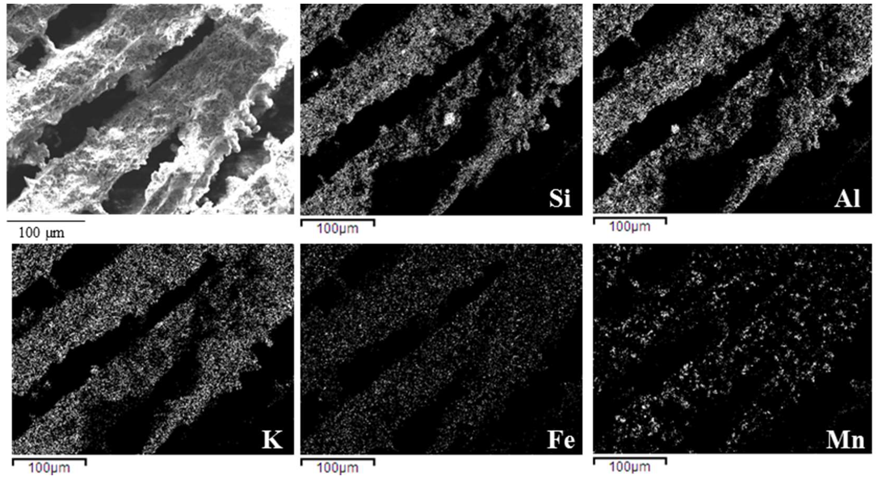
The EDS element maps of Si, Al, K, Fe, and Mn (Figure 4) showed a continuous and quite regular presence of the elements constituting the geopolymer matrix (Si, Al, K) and of the metal oxides added to produce the composites. The maps of Mn evidenced a wider dimensional range for Mn2O3 powder, compared with Fe2O3, as previously found by granulometric analysis [6], where the d0.9 (the upper limit of the dimension of the 90% of the particles) was 1.5 and 8.9 µm, respectively, for Fe2O3 and Mn2O3.

3.2. Macro- and Micro Structural Characterization: Beads

In general, the dripping of the composite mixtures into liquid N2 allowed obtainment of spherical beads of 23 mm, with the exception of the mixture conceived with the highest solid loading (MnFe40B) that was too dense and not adequate for the adopted process.
In Figure 5, a picture of the produced beads is reported. MnFe55B beads (Figure 5a) were more homogenous with a controlled diameter around 2.5 mm. With the increase of the H2O vol.%, the obtained beads were less homogeneous with a more dispersed size distribution. Indeed, for MnFe70B and MnFe80B (Figure 5b,c), the formation of bigger beads due to the coalescence of adjacent droplets was evident. It was already reported [18] that if several droplets are deposited on the interface at the same time, they move together and (if this aggregation occurs before the drops freeze) coalesce into a larger drop. This aggregation is attributed to the interfacial deformations caused by each droplet, which are well-known to cause floating bodies to aggregate, as described by the “Cheerios effect” [19].
The process adopted was optimized to avoid the “Cheerios effect” by keeping the dripped beads separated; however, the high water content in MnFe70B and MnFe80B prolonged the beads’ freezing time, so that the dripped beads tended to coalesce with the previously dripped ones, which were not entirely frozen.
As reported for MnFe80M, the high water content (80 vol.%) led to a separation of the silicate in the mixture and the resulting beads (MnFe80B, Figure 5c) showed the formation of whiter domains on their surfaces, due to the presence of residual silicate. Therefore, also in the case of the bead production, the best performing slurry for the process was MnFe55B. The beads obtained from MnFe55B formulations were, therefore, selected and further characterized.
The process parameters adopted allowed obtainment of spherical and uniform beads (Figure 5a), since the radius of the needle combined with the density of the mixtures let the beads levitate on the liquid N2 before sinking. Indeed, the drops interact with liquid N2 following the “inverse” Leidenfrost effect [18]; drops levitate because heat passes from the (relatively warm) drop to the liquid bath beneath it, and in doing so, causes the liquid to evaporate, leading to the formation of a supporting vapor layer [18]. The droplet contains only a finite amount of thermal energy, and since the evaporation of the liquid nitrogen requires the supply of latent heat to the bath, the temperature of the droplet decreases until it first freezes itself (releasing latent heat of fusion in the process), before cooling further and ultimately reaching the Leidenfrost temperature of the liquid nitrogen. At this point, film boiling ceases, the vapor layer disappears, and the droplet sinks into the bath [18].
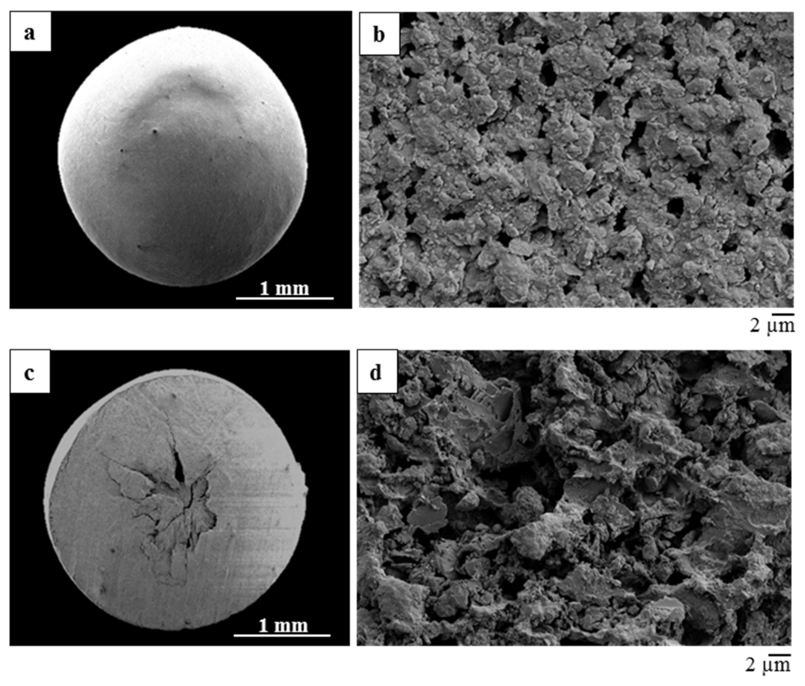
The spherical shape of the beads is evidenced in the SEM micrograph reported in Figure 6a. The microstructure of the external part of the beads was smooth and dense, with the presence of homogeneously distributed small, round pores of around 2 µm diameter (Figure 6b), firstly due to fast freezing [12]. Flat geopolymer precipitates were also observed (Figure 6c). Lamellar structures were not seen on the surface and pore inlets were round; these may be related to the “inverse” Leidenfrost effect [18], as mentioned before.
The cross section of the bead (Figure 6d) revealed the presence of a hole in the center. This was due to the formation of the porous structure that occurred in a radial way, aligning along the temperature gradient inside the bead. Indeed, the freezing direction occurred from the external part of the bead directly in contact with the liquid nitrogen vapor, towards the warmer center of the bead.
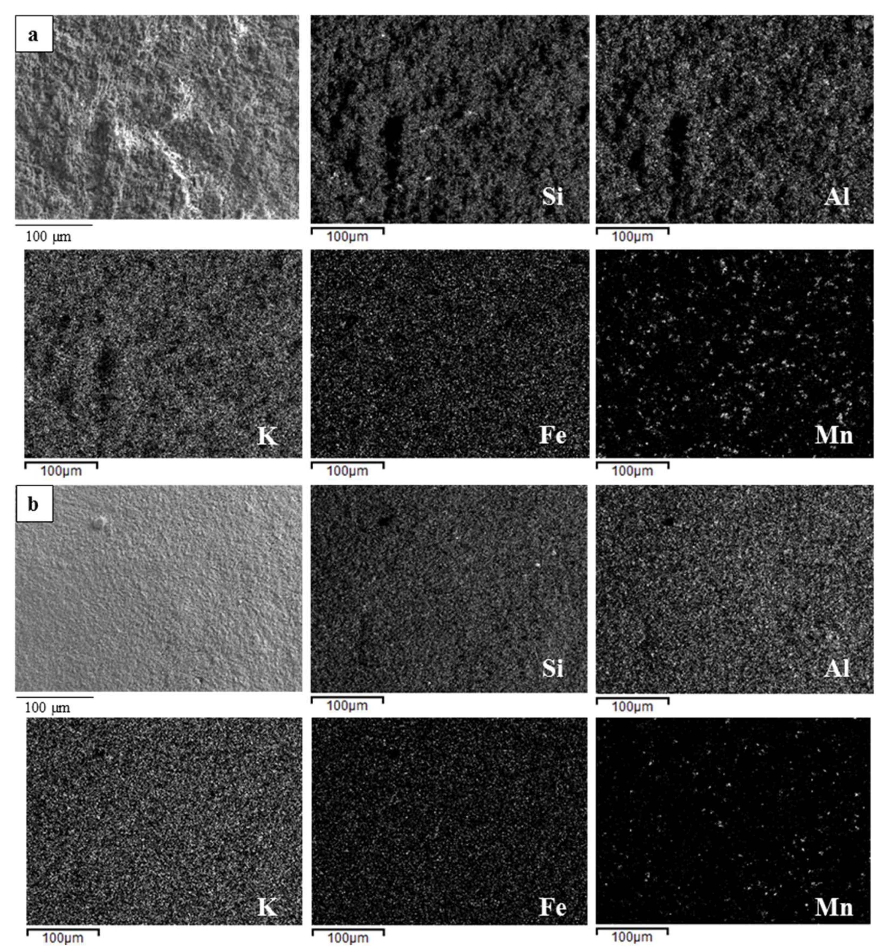
Figure 7 reports the EDS element maps of Si, Al, K, Fe, and Mn of the inner (Figure 7a) and external (Figure 7b) part of the bead. The inner part showed a continuous and quite regular presence of the elements constituting the geopolymer matrix (Si, Al, K) and of the metal oxides added to produce the composites. The external part revealed a pauperization of Mn, as the outside was richer in silicate/water, which freezes first, while the heavier and agglomerated particles of Mn2O3 [6] remained inward.

3.3. Porosity and Accessibility of the Composites Inner Volume

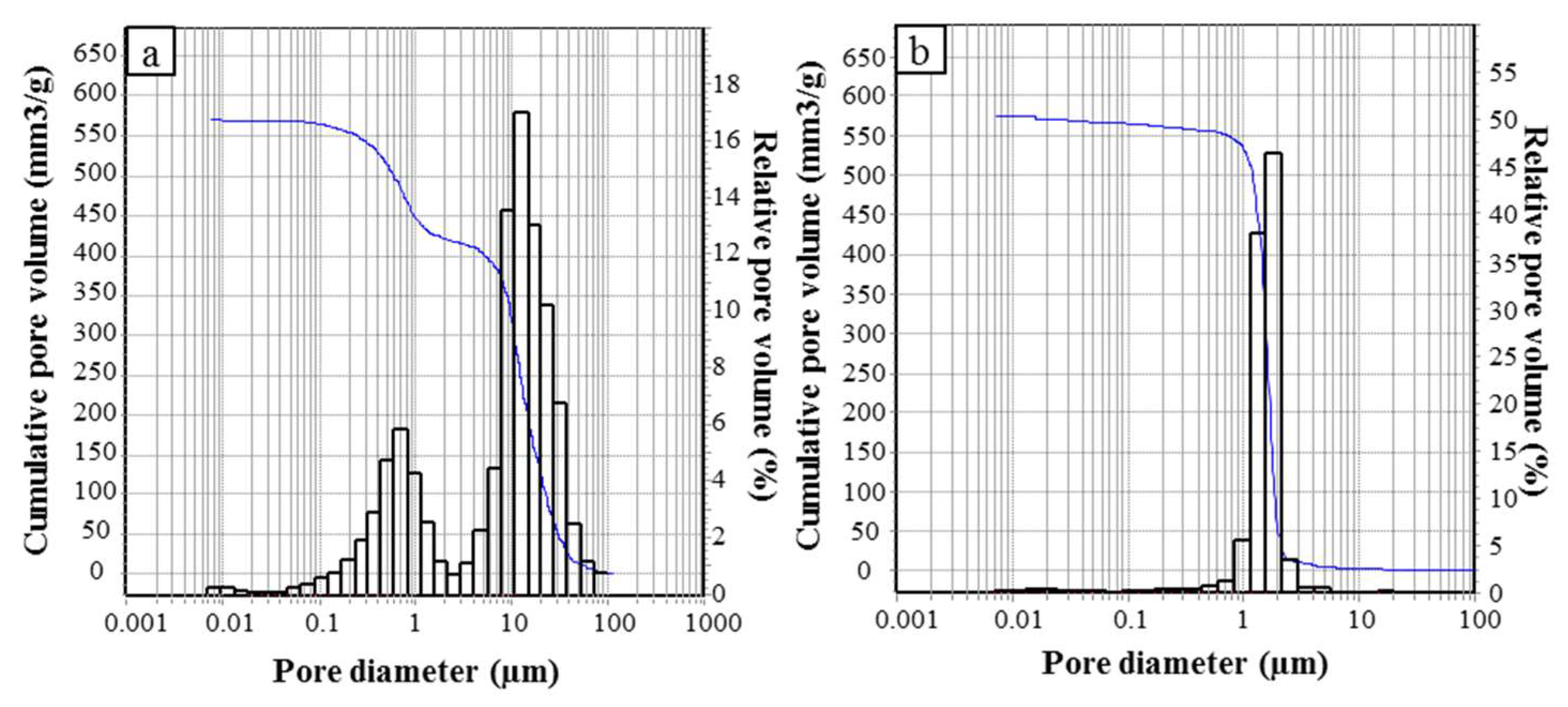
The porosity of the monoliths and beads, obtained with the best performing and selected mixture, MnFe55, was investigated through mercury intrusion porosimetry. The pore size distributions obtained for the monolith and the beads are reported in Figure 8. The results obtained account both for the intrinsic porosity of the geopolymer composite matrix and for the smallest macro-pores formed by ice-templating.
The pore size distribution of the monolith MnFe55M (Figure 8a) was bimodal, with main peaks detected at 0.7 and 12 µm. Pores ranging from 0.0058 to 1 µm were related to the intrinsic porosity of the geopolymer matrix, while pores ranging from 1 to 100 µm were attributable to the ice-templating process. Conversely, the pore size distribution of the MnFe55B beads (Figure 8b) was monomodal and centered at 1.6 µm.
The beads and the monoliths possessed similar total porosity % and total pore volume, being ≈65% and 570 mm3 g−1, respectively, as reported in Table 2. The differences in the pore size distribution could be attributed to the different shaping. Hg porosimetry was conducted on the entire beads, and therefore Hg was forced to pass into the pores present on the external part of the beads, spreading then into the inner volume (ink-bottle effect). As observed in the SEM micrograph (Figure 6b), the external surface is composed by homogeneously distributed rounded pores of around 2 µm diameter, consistent with the modal pore diameter detected by Hg porosimetry of 1.6 µm. Once the mercury is forced inside the beads, the open porosity resembles the porosity found for the material shaped in the monolith form, hence the final total porosity and the total pore volume are almost the same for the two differently shaped composites.
Laminated monoliths with thin pore widths and walls are interesting structures for improving the volumetric efficiency and reducing the cycle time. The unique directionality of the porosity can be used to optimize the species transport properties, decreasing the pressure drop, while the dense walls will ensure optimal conducting properties and mechanical reliability [12]. Conversely, particle packing with beads can enhance the mass and heat transfer. Since the permeability and mass transfer capability of the carriers are opposite, it is difficult to decide which carriers could be more advantageous from the viewpoint of a maximal mass transfer at a minimal pressure drop [20]. Furthermore, there is a substantial influence of the type of porosity on the mass transfer, not only on the total porosity %, which in this case is similar for the two carriers. Therefore, both the carriers could be suitable for a packed bed reactor configuration.
The similar microporosity is confirmed also by the values of specific surface area (Table 2) that were very similar, being 2.47 m2 g−1 for the monolith and 2.92 m2 g−1 for the beads.
The relatively low values obtained, if compared with the typical values of metakaolin-based geopolymers that come up to 100 m2 g−1, are due to the applied conditioning treatment. Indeed, sintering for viscous flow starts at 900 °C, leading to a densification and pore occlusion of the geopolymer composite material, with a consequent decrease of the specific surface area.

4. Conclusions

The freeze-casting technique, applied to geopolymer-Fe/Mn oxide composites, was successful for the production of highly porous monoliths and beads, conceived as potential oxygen carriers for CLC processes with a packed bed configuration.
In general, the simultaneous formation of geopolymer intrinsic mesoporosity and macro-porosity by ice growth, together with a final chemical consolidation, was obtained by properly combining the maturation step of the geopolymer reactive system with the water targeted for the ice-templating.
A water amount of 55 vol.% was optimal for the process and suitable for the formation of both monoliths and beads.
The monoliths showed the formation of a unidirectional lamellar porosity arranged in domains, running form the bottom to the top of the sample. The direct dripping of the mixture in liquid nitrogen lead to the formation of rounded beads with ~2.5 mm diameter.
The differently shaped materials possess a comparable porosity, albeit with a different pore size distribution, due to the development of a different macroporosity during the ice-templating.
In both cases, the process led to obtain porous and homogeneous microstructures, with well-dispersed metal oxides inside the geopolymer matrix.
Therefore, both the carriers could be suitable for a packed bed reactor configuration; studies are ongoing to further improve the process conditions and the differently shaped oxygen carriers will be tested in a lab-scale CLC plant to assess the performances in terms of CO conversion and oxygen transport ability.
Author Contributions

Conceptualization, E.L. and F.M.; methodology, E.P., V.M., and E.L.; formal analysis, E.P. and A.N.M.; investigation, E.P. and A.N.M.; writing—original draft preparation, E.P.; writing—review and editing, E.L, V.M., and A.N.M.; funding acquisition E.L, V.M., and F.M.

Funding

This research received no external funding.

Acknowledgments

The authors greatly thank A. Piancastelli for MIP analyses.

Conflicts of Interest

The authors declare no conflict of interest. The founding sponsors had no role in the design of the study; in the collection, analyses, or interpretation of data; in the writing of the manuscript, and in the decision to publish the results.

References

  1. Davidovits, J. Geopolymers Chemistry and Applications; Institut Geopolymere: Saint-Quentin, France, 2008. [Google Scholar]
  2. Kriven, W.M.; Bell, J.L.; Gordon, M. Microstructure and microchemistry of fully-reacted geopolymers and geopolymer matrix composites. Ceram. Trans. 2013, 153, 227–250. [Google Scholar]
  3. Landi, E.; Medri, V.; Papa, E.; Dedecek, J.; Klein, P.; Benito, P.; Vaccari, A. Alkali-bonded ceramics with hierarchical tailored porosity. Appl. Clay Sci. 2013, 73, 56–64. [Google Scholar] [CrossRef]
  4. Bendoni, R.; Miccio, F.; Medri, V.; Landi, E. Chemical looping combustion using geopolymer-based oxygen carriers. Chem. Eng. J. 2018, 314, 187–197. [Google Scholar] [CrossRef]
  5. Miccio, F.; Bendoni, R.; Piancastelli, A.; Medri, V.; Landi, E. Geopolymer composites for chemical looping combustion. Fuel 2018, 225, 436–442. [Google Scholar] [CrossRef]
  6. Bendoni, R.; Miccio, F.; Medri, V.; Benito, P.; Vaccari, A.; Landi, E. Geopolymer composites for the catalytic cleaning of tar in biomass-derived gas. Renew. Energy 2019, 131, 1107–1116. [Google Scholar]
  7. Rubin, E.S.; Zhai, H. The cost of carbon capture and storage for natural gas combined cycle power plants. Environ. Sci. Technol. 2012, 46, 3076–3084. [Google Scholar] [CrossRef] [PubMed]
  8. Adanez, J.; Abad, A.; Garcia-Labiano, F.; Gayan, P.; De Diego, L.F. Progress in chemical-looping combustion and reforming technologies. Prog. Energy Combust. Sci. 2012, 38, 215–282. [Google Scholar] [CrossRef]
  9. Miccio, F.; Piriou, B.; Ruoppolo, G.; Chirone, R. Biomass gasification in a catalytic fluidized reactor with beds of different materials. Chem. Eng. J. 2009, 154, 369–374. [Google Scholar] [CrossRef]
  10. Papa, E.; Medri, V.; Benito, P.; Vaccari, A.; Bugani, S.; Jaroszewicz, J.; Swieszkowski, W.; Landi, E. Synthesis of porous hierarchical geopolymer monoliths by ice-templating. Microporous Mesoporous Mater. 2015, 215, 206–214. [Google Scholar] [CrossRef]
  11. Papa, E.; Medri, V.; Benito, P.; Vaccari, A.; Bugani, S.; Jaroszewicz, J.; Landi, E. Insights into the macroporosity of freeze-cast hierarchical geopolymers. RSC Adv. 2016, 6, 24635–24644. [Google Scholar] [CrossRef]
  12. Deville, S. Freeze-casting of porous ceramics: A review of current achievements and issues. Adv. Eng. Mater. 2008, 10, 155–169. [Google Scholar] [CrossRef]
  13. Li, W.L.; Lu, K.; Walz, J.Y. Freeze casting of porous materials: Review of critical factors in microstructure evolution. Int. Mater. Rev. 2012, 57, 37–60. [Google Scholar] [CrossRef]
  14. Deville, S.; Saiz, E.; Tomsia, A.P. Ice-templated porous alumina structures. Acta Mater. 2007, 55, 1965–1974. [Google Scholar] [CrossRef] [Green Version]
  15. Mukai, S.R.; Nishihara, H.; Tamon, H. Porous microfibers and microhoneycombs synthesized by ice templating. Catal. Surv. Asia. 2006, 10, 161–171. [Google Scholar] [CrossRef] [Green Version]
  16. Noorman, S.; van Sint Annaland, M.; Kuipers, H. Packed bed reactor technology for Chemical-Looping Combustion. Ind. Eng. Chem. Res. 2007, 46, 4212–4220. [Google Scholar] [CrossRef]
  17. Hakouk, K.; Klotz, M.; Di Geronimo, E.; Ranieri, V.; Pieterse, J.A.Z.; Aranda Almansa, G.; Steele, A.M.; Thorpe, S. Implementation of novel ice-templated materials for conversion of tars from gasification product gas. Fuel Process. Technol. 2018, 181, 340–351. [Google Scholar] [CrossRef]
  18. Adda-Bedia, M.; Kumar, S.; Lechenault, F.; Moulinet, S.; Schillaci, M.; Vella, D. Inverse Leidenfrost Effect: Levitating Drops on Liquid Nitrogen. Langmuir 2016, 32, 4179–4188. [Google Scholar] [CrossRef] [PubMed]
  19. Vella, D.; Mahadevan, L. The “Cheerios effect”. Am. J. Phys. 2005, 73, 817–825. [Google Scholar] [CrossRef]
  20. Patcas, F.C.; Garrido, G.I.; Kraushaar-Czarnetzki, B. CO oxidation over structured carriers: A comparison of ceramic foams, honeycombs and beads. Chem. Eng. Sci. 2007, 62, 3984–3990. [Google Scholar] [CrossRef]
Figure 1. Flow chart of the freeze-casting process adopted to produce the composite monoliths and beads.
Ceramics 02 00014 g001
Figure 2. Pictures of the composite monoliths: (a) MnFe40M, (b) MnFe55M, (c) MnFe70M, and (d) MnFe80M.
Ceramics 02 00014 g002
Figure 3. MnFe55M monolith: digital microscope images (a,b) and SEM micrographs (c,d) of top surface (a,c) and longitudinal cross section (b,d).
Ceramics 02 00014 g003
Figure 4. EDS Elemental maps of Si, Al, K, Fe, and Mn on the lamellar microstructure of MnFe55M.
Ceramics 02 00014 g004
Figure 5. Pictures of the composite beads: (a) MnFe55B, (b) MnFe70B, and (c) MnFe80B.
Ceramics 02 00014 g005
Figure 6. SEM micrographs of MnFe55B: external part (a,b), inner part (c,d).
Ceramics 02 00014 g006
Figure 7. EDS Elemental maps of Si, Al, K, Fe, and Mn on the bead inner (a) and external (b) part.
Ceramics 02 00014 g007
Figure 8. Pore size distributions measured by Hg intrusion porosimetry of the MnFe55M (a) and MnFe55B (b).
Ceramics 02 00014 g008
Table 1. Sample code and water vol.% for the ice-templating process. Bulk, true density, and total porosity of the monoliths and tap density of the beads.
Monoliths Sample CodeH2O (vol.%)Bulk Density (g cm−3)True Density (g cm−3)Total Porosity (%)
MnFe40M401.312.8354
MnFe55M551.052.8363
MnFe70M700.752.8373
MnFe80M800.512.8182
Beads Sample CodeH2O (vol.%)Tap Density (g cm−3)
MnFe55B550.57
MnFe70B700.40
MnFe80B800.30
Table 2. Total porosity, total pore volume, and modal pore diameter measured by mercury porosimetry and specific surface area (SBET).
Sample CodeCarrier ShapePorosity by Hg Intrusion (%)Modal Pore Ø (µm)Total Pore Volume (mm3 g−1) SBET (m2 g−1)
MnFe55Mmonoliths65.0712.05572.202.47
MnFe55Bbeads62.421.61567.082.92