Article

Development of a Control System for Pressure Distribution During Gas Production in a Structurally Complex Field

1
System Analysis and Control Department, Empress Catherine II Saint Petersburg Mining University, 199106 Saint Petersburg, Russia
2
Faculty of Computer Science and Technology, Saint Petersburg Electrotechnical University “LETI”, 197022 Saint Petersburg, Russia
*
Author to whom correspondence should be addressed.
Appl. Syst. Innov. 2025, 8(2), 51; https://doi.org/10.3390/asi8020051
Submission received: 28 December 2024 / Revised: 25 March 2025 / Accepted: 7 April 2025 / Published: 10 April 2025

Abstract

:
In recent times, gas is becoming one of the most significant resources utilised worldwide. The continuous increase in demand requires an increase in the production and preparation of gas for further utilisation. Conventional sources cannot satisfy this need, so it is necessary to resort to alternative methods of obtaining raw materials; one of the most promising is the development of unconventional reservoirs. The study considers a structurally complex gas-bearing reservoir; due to the peculiarities of the structure, the use of traditional approaches to gas production causes a number of difficulties and significantly reduces efficiency. A structurally inhomogeneous reservoir is considered a distributed object; a pressure field control system is synthesised. As a result, the efficiency of the system is evaluated, and its scalability is analysed.

1. Introduction

The modern world is characterised by a constant increase in demand for energy resources, and the current volumes of extracted raw materials cannot fully satisfy the demand. In this regard, there is a tendency of continuous improvement of technologies of extraction, preparation, and transportation of hydrocarbon resources [1], but the overall impact on volumes is insignificant, as natural gas is widely used in many areas [2].
One of the most prospective alternatives is the development of unconventional fields [3,4,5]. These include hard-to-extract hydrocarbons, in particular, reservoirs with complex structures [6,7,8]. A huge amount of natural gas reserves belongs to this type of raw material and is considered one of the most promising ways to replenish the production of energy supply resources [9,10,11].
At present, the development of fields with complex geological structures is being actively carried out while using technologies that cannot fully ensure a truly high efficiency of exploitation of these deposits. Currently, the study of structurally complex reservoirs is approached from different aspects, and a number of studies are aimed at investigating the process of reservoir formation and the problems arising from the complex structure [12,13,14]. Multilayer structure and issues of fluid interaction between layers are considered [15,16,17]. A number of works are aimed at studying petrophysical [18,19,20] and lithological properties of reservoirs [21,22,23] in order to identify certain relationships [24,25,26]. In addition to traditional approaches for determining the petrophysical properties of reservoirs, new methods of automated mineralogy have recently been actively developed [27,28]. Also, during reservoir development, it is necessary to take into account high values of temperature and pressure characteristic of this type of field [29,30,31].
At present, the main part of research is aimed at studying the processes of hydrocarbon fluid movement in reservoirs, as well as general studies of reservoir properties [32,33,34]. Not much research attention is paid to the control processes during gas production in these types of reservoirs.
This paper proposes to consider a gas-producing horizon as an object with distributed parameters. Real objects in the oil and gas field are mostly distributed in space (pipelines, oil, and gas-bearing reservoirs, etc.), which makes it impossible to consider them as concentrated objects, as this will lead to large inaccuracies and inconsistencies with the actual processes [35,36,37]. The application of distributed control systems (DCS) significantly improves the system’s efficiency, and as a consequence, a favourable economic effect of DCS implementation is observed [38,39,40].
The analytical review of the research topic shows that the study of unconventional oil and gas reservoirs with complex geological structure is an urgent task all over the world. The heterogeneity of the structures causes significant difficulties in the study and development of reservoirs, which requires the development of fundamentally new approaches to their solution. The purpose of this work is to form an algorithm for controlling the dynamics of pressure distribution in a structurally complex gas condensate field, which allows for an increase in the economic efficiency of the field exploitation process. The object of the study is the Achimov deposits of the Urengoy oil and gas condensate field (OGCF).

2. Materials

The geological structure of the Urengoy OGCF includes various rocks represented by pre-Palaeozoic and Palaeozoic metamorphic rocks and platform cover sediments composed of polyfacial terrigenous sandy–clay–siltstone rocks of Palaeozoic and Mesozoic–Cenozoic ages. The paper deals with the Cretaceous system, in which it is customary to distinguish two different divisions, upper and lower, with the features and composition characteristic of each one. The study considers a part of the Lower Tier due to the fact that the Bazhenov Formation is at the base of which the Achimov Formation is formed.
From the geological point of view, the Achimov sediments are extremely heterogeneous, characterised by interlacing clayey rocks, lenticular sandstones, and siltstones (Figure 1). This complex structure explains all the difficulties encountered by specialists in the development and operation of oil and gas fields in this formation.
Achimov deposits are characterised by a high degree of layering, which is one of the most important problems in the exploitation of deposits of this type. Layers of different interlayers may consist of fine-grained sandstones and different clay formations with carbonate–clay cement. This variable structure affects the processes of hydrocarbon movement within the reservoir and its filtration. The thickness of the Achimov deposits varies from 80 to 418 m.
During the study of the Achimov formations by various methods (exploration drilling, seismic survey), scientists have characterised the structure of the Achimov formations as lenticular discontinuous [42,43]. Gas–condensate–oil deposits belonging to the Achimov strata depend on the combined lithological structure of the formation, which can be regarded as separate blocks of rock with their own capacitive-filtration properties, so the distribution of hydrocarbons also depends on the depth variations.
The gas condensate complex (GCP), on the basis of which the research object is located, is developed using the cluster method. Each cluster is formed by a number of wells from three to five units, with a maintained distance between them of up to 70 m.
Analysing the geological structure of the Achimov oil and gas-bearing strata, we can conclude that they are characterised by a complex type of structure, which creates complications in the process of their development and exploitation. Filtration-capacitance properties characteristic of Achimovka are low. Porosity values do not exceed 20%; permeability of the strata is estimated to be 10–15 m2. In addition, anomalously high temperature and pressure values (from 105 °C to 115 °C and from 59 to 61 MPa, respectively) are observed in the deposits of this type.

3. Methods

The research methodology is based on a step-by-step study of the object. The primary analysis and formalisation of the area and object of research allow for the formulation of the aims and objectives accurately. The analysis of the technological process of gas production in fields with complex geological structures is presented in the previous studies. On the basis of this analysis, it was established that the controlling influence is the underbalance on the reservoir; the controlled variables are the pressure at the wellhead and the well flow rate [44,45,46]. In this connection, we determine that the most important parameter of the system under study is pressure, namely, the pressure distribution within the reservoir [47,48,49]. With the further formalisation of the object of study, a conceptual model was developed, which allowed us to determine the list of the most significant factors in the process of gas production [50].
When developing a mathematical model of the process under study, it is necessary to determine the physical processes and phenomena characteristic of this object on the basis of the developed conceptual model. Then the known dependencies are adapted to the solution of a particular problem. This process is based on the use of differential calculus, regression analysis, and analytical and numerical methods of solving differential equations [51].
The representation of the mathematical model should satisfy the requirement that it can be implemented in a computer simulation of the investigated process. For this purpose, the mathematical model represented in the form of partial differential equations with its initial and boundary conditions must be translated into a form suitable for computer modelling. This is realised by using numerical solutions of differential equations, resulting in a discrete model that can be implemented on a computer. The control system synthesis procedure [52,53] is based on the frequency synthesis method [54] for systems with distributed parameters.
The adopted methods within the framework of this research form an integrated approach to the study of the management object, which allows for obtaining its representation in formalised and mathematical form, as well as for implementing the modelling of the processes under study.

4. Development of a Mathematical Model of Pressure Distribution in a Structurally Complex Reservoir

Prior to the development of any gas-bearing horizon, it is generally assumed that the pressure in the entire reservoir is conditionally equal. However, since the beginning of exploitation, pressure distribution has been non-uniform, and this process is influenced by many factors: development mode, production volume, properties of individual reservoir sections, heterogeneity of the structure, etc. All this suggests that the pressure in different points of the reservoir is formed as a single field distributed over space.
Proceeding from the fact that the reservoir is an object with a heterogeneous structure, its description is built using a layered model, in which each individual section (layer) may have its own properties. Let us represent the gas-bearing horizon under study as a parallelepiped (Figure 2).
Let us denote the main parameters of the modelling object. It is divided into 27 blocks in the three-dimensional domain.
Geometric dimensions of the modelled system:
x L = 210 m , y L = 210 m , z L = 120 m .
Each unit of the system has the following geometrical dimensions:
x B = 70 m , y B = 70 m , z B = 30 m .
In the framework of the study, the system is considered to be non-deformable, thus the porosity of the blocks does not change with time. The system is also considered to be isotropic.
When forming the mathematical model, the equation of pressure distribution in a gas-bearing deposit represented in three-dimensional pro-space (the equation of academician L.S. Leibenzon) was taken as a basis for the formation of the mathematical model [55]:
( ρ m ) d t = k μ 2 p x 2 + 2 p y 2 + 2 p z 2 ,
where m is the porosity of the gas-bearing formation; μ —absolute gas viscosity; ρ —gas density; p = p ( x , y , z , t ) —gas pressure at time t ; x , y , z —coordinates; x L , y L , z L —final coordinates along the axes x , y , z ; 0 < x < x L , 0 < y < y L , 0 < z < z L ; and k —permeability of the gas-bearing formation.
The Leibenzon function for a perfect gas is defined by the formula:
p = ρ a m p 2 2 p a m + C ,
where ρ a t m —gas density at atmospheric pressure and p a t m —atmospheric pressure.
Then, differentiating Equation (2) by coordinates two times, taking into account the equation of state of an ideal gas, we obtain for the left part of (1):
( ρ m ) d t = ρ a m m 0 p a m p d t ,
where m 0 = m —is the porosity of the gas-bearing reservoir at p = p 0 .
Considering this and the differentiated expression (2), substituting into (1), we obtain:
p d t = k 2 × μ × m 2 p 2 x 2 + 2 p 2 y 2 + 2 p 2 z 2 .
The Leibenzon equation [56] can be written in another form by multiplying the right and left parts by p and substituting:
p p d t = 1 2 p 2 d t .
Transform Equation (3) to the following form:
p 2 d t = k × p 0 μ × m 2 p 2 x 2 + 2 p 2 y 2 + 2 p 2 z 2 ,
where p 0 is the initial pressure of the gas-bearing reservoir.
Introduce the substitution P = p n + 1 n , where n —the polytropy exponent is equal to 1; from (4), we obtain:
P d t = k × p 0 μ × m 2 P x 2 + 2 P y 2 + 2 P z 2 .
To implement the modelling, it is necessary to determine the initial and boundary conditions of the system under study. At the zero moment of time (i.e., the beginning of gas condensate reservoir development), the pressure in the reservoir is considered to be equally dimensionally distributed over the entire reservoir area; in other words,
p ( x , y , z , 0 ) = p 0 ,
where p 0 = 60   M P a .
On the boundaries of the object, the boundary conditions of the second kind are fulfilled; in other words, the boundaries of the cluster are considered impermeable:
p ( x L , y , z , t ) x = 0 ; p ( 0 , y , z , t ) x = 0 ; p ( x , 0 , z , t ) y = 0 ; p ( x , y L , z , t ) y = 0 ; p ( x , y , 0 , t ) z = 0 ; p ( x , y , z L , t ) z = 0 ,
where t 0 .
Boundary conditions for the sides of the model blocks are given in the form of a flow equality condition. Along the Y-axis:
χ 1 ( P 1 , l y ) = χ 2 ( P 2 , l y ) , χ 2 ( P 2 , l y ) = χ 3 ( P 3 , l y ) , χ 4 ( P 4 , l y ) = χ 5 ( P 5 , l y ) , χ 5 ( P 5 , l y ) = χ 6 ( P 6 , l y ) , χ 7 ( P 7 , l y ) = χ 8 ( P 8 , l y ) , χ 8 ( P 8 , l y ) = χ 9 ( P 9 , l y ) ,
where 1 < l < 4 ; χ i = k i μ i ( m i β g + β r ) –piezoconductivity coefficient of the block; 1 < i < 9 ; β g , β r —gas and rock compressibility coefficient.
Conditions of equality of flows between blocks along the X-axis:
χ 1 ( P 1 , l x ) = χ 4 ( P 2 , l x ) , χ 4 ( P 2 , l x ) = χ 7 ( P 3 , l x ) , χ 2 ( P 4 , l x ) = χ 5 ( P 5 , l x ) , χ 5 ( P 5 , l x ) = χ 8 ( P 6 , l x ) , χ 3 ( P 7 , l x ) = χ 6 ( P 8 , l x ) , χ 6 ( P 8 , l x ) = χ 9 ( P 9 , l x ) .
Conditions of equality of flows between blocks along the Z-axis:
χ 1 ( P i , 1 x ) = χ 2 ( P i , 2 x ) , χ 2 ( P i , 2 x ) = χ 3 ( P i , 3 x ) .
Applying the finite difference method, we obtain the solution of the differential Equation (1) in numerical form:
Δ P i , j , f Δ t = k × p 0 μ × m P i 1 , j , f 2 P i , j , f + P i + 1 , j , f Δ x 2 + P i , j 1 , f 2 P i , j , f + P i , j + 1 , f Δ y 2 + + P i , j , f 1 2 P i , j , f + P i , j , f + 1 Δ z 2 ,
where i = 1 , I ¯ ; j = 1 , J ¯ ; f = 1 , F ¯ ; Δ x , Δ y , Δ z —axis sampling steps X, Y, Z; I, J, F—number of sampling points along the axes X, Y, and Z, respectively.
Initial (10) and boundary (11) conditions in discrete form:
p ( i , j , f , 0 ) = p 0 .
p ( 0 , j , f , t ) = p ( 1 , j , f , t ) , p ( I , j , f , t ) = p ( I 1 , j , f , t ) , p ( i , 0 , f , t ) = p ( i , 1 , f , t ) , p ( i , J , f , t ) = p ( i , J 1 , f , t ) , p ( i , j , 0 , t ) = p ( i , j , 1 , t ) , p ( i , j , F , t ) = p ( i , j , F 1 , t ) .
The rate of decline and distribution of reservoir pressure in a gas-producing well can be controlled by limiting the pressure in the wells. This work will analyse the downhole pressure at the bottom of the wells.
Equation (4), in combination with initial conditions (6), boundary conditions (7), and flow conditions at media boundaries (8) and (9), completely describes the gas-bearing reservoir as a control object. The obtained numerical model (11), (12), (13) is the basis for further synthesis of a distributed control system for pressure distribution during gas production in fields with complex geological structures.

5. Results

The developed mathematical model of pressure distribution in a structurally complex reservoir is implemented in the Python programming 3.12 environment. The input influence is the pressure levels at the location points of producing wells, formed in the form of selected spatial modes with certain numbers (spatial frequencies):
p ( i z , j z , f z , t ) = U ( x , y ) ,
where U ( x , y ) = A + A cos π ξ L x x cos π γ L y y ; A —input amplitude; ξ and γ —numbers of spatial modes in x and y, respectively; L x and L y —object dimensions along X and Y axes, respectively; p —target pressure; i z , j z , f z —wellbore coordinates of the z-th wellbore in the deposit.
This study considers modelling a section of a gas-bearing horizon containing nine wells. At the output of the system, we determine the level distribution in the given (control) points of the reservoir. The points at the bottom of the producing wells will be considered as control points.
Investigate the behaviour of the model when an input disturbance is applied to it. In Equation (12), assume the amplitude of the input influence A = 40 M P a . Spatial modes ξ 1 = 1 , ξ 2 = 3 and γ 1 = 1 , γ 2 = 3 . By applying influences on the model for each pair of modes, we obtain the following transient plots (Figure 3 and Figure 4).
In all graphs in this chapter, the solid blue line represents the well transient in Block 6. By analysing the transient graph of mode 1 and mode 3 shown in Figure 3 and Figure 4, we can conclude that the transfer function (TF) of the object W i ( G , s ) for each mode can be represented as an aperiodic link of the first order with a delay:
W i ( G , s ) = k i ( G ) T i ( G ) s + 1 e τ s ,
where T i ( G ) —time constant of the object by i-th mode: k i ( G ) —gain of the object by i-th mode; τ i —delay time by i-th mode; s —Laplace operator; G —generalised coordinate; i = 1 , 3 .
The gain is determined by the formula
k i ( G ) = y e q u , i x i n , i ,
where y e q u —steady-state transient value and x i n —system input.
According to the results of modal modelling of the distributed object, the following results were obtained y e q u , 1 = 46 . 7 M P a and y e q u , 3 = 43.7 M P a . The input impact is calculated by the formula:
U i ( x , y ) = A i + A i cos π ξ i L x x cos π γ i L y y .
Substituting all values into Formula (15), we obtain the values of the input influence: U 1 ( x , y ) = 48.96 M P a and U 3 ( x , y ) = 40 M P a . The obtained values are used in Formula (14), and we obtain the gain of TF:
k 1 ( G ) = 46 . 7 48.96 = 0.95 , k 3 ( G ) = 43 . 7 40 = 1.09 .
We determine the time constant T 1 ( G ) and the delay time τ 1 by approximating the transient graph (Figure 3).
According to the graph in Figure 5, determine the value of T 1 ( G ) = 8 h , τ = 1 . Thus, the TF of the object by mode 1 will take the following form:
W 1 ( G , s ) = 0.95 8 s + 1 e s .
According to the graph in Figure 6, determine the value T 3 ( G ) = 6 h , τ 3 = 1 . Thus, the TF of the object by mode 3 will take the following form:
W 3 ( G , s ) = 1.09 6 s + 1 e s .
Having obtained the TF of the object by modes 1 and 3, let us proceed to the synthesis of a distributed control system; namely, we develop a distributed high-precision controller (DHC), the TF of which has the following form [52,57]:
W ( x , s ) = E 1 n 1 1 n 1 1 n 1 2 + E 4 n 4 1 n 4 1 n 4 2 1 s + E 2 n 2 1 n 2 1 n 2 2 s ,
where E 1 , E 2 , E 4 —gain coefficients of distributed proportional, integrating and differentiating blocks; n 1 , n 2 , n 4 —weight coefficient, 2 —laplacian.
Application of DHC in this system is necessary to regulate the pressure distribution in the reservoir during field operation to the required value, which is set at the beginning of modelling. This will result in a closed-loop system for controlling the pressure field during gas production in structurally complex fields.
Assume that the phase shift introduced into the system by the controller is zero. Then, we define the cut-off points of the open-loop module.
π + Δ φ = a r c t g ( Im ( W ( G , j ω ) / Re ( W ( G , j ω ) ) ,
where W ( G , j ω ) —complex transfer coefficient of the control object.
Using Equation (21) for the selected spatial modes ( G 1 И G 3 ), we determine the cut-off frequencies ω 1 = 1.155 , ω 3 = 1.18673 . At this frequency, according to the relationship:
K ( G ) = Im ( W ( j ω ) 2 + Re ( W ( j ω ) 2 .
Define k o b , 1 = 0.1 , k o b , 3 = 0.15 . By the ratio, we find the regulator coefficient we obtain k r e g , 1 = 10 , k r e g , 3 = 6.67 .
To determine all parameters of the DHC, we calculate the values of generalised co-ordinates G 1 and G 3 based on the numbers of spatial modes:
G 1 = π i L x 2 + π j L y 2 = 0.00045 . G 3 = π i L x 2 + π j L y 2 = 0.00403 .
Define E 1 and n 1 by the system of equations
1 К o b , 1 = E 1 n 1 1 n 1 G 1 n 1 , 1 К o b , 3 = E 1 n 1 1 n 1 G 3 n 1 .
From the system (22) express n 1 , for this purpose, we divide the equations into each other:
n 1 =   1 + Δ K Δ K G 1 + G 3 Δ K 1 .
Considering that Δ K = K r e g , 3 K r e g , 1 = 6.67 10 = 0.67 , and substituting the values of G 1 and G 3 , we obtain the value of
n 1 =   1 + 0.67 0.67 0.00045 + 0.00403 0.67 1 = 0.98 .
Considering that n 1 1 , n 2 1 , n 4 1 , we assume n 1 = 1 .
Substituting n 1 into the first Equation (22), we obtain
E 1 = K r e g , 1 n 1 1 n 1 + G 1 n 1 = 22 , 341 .
Based on the equation of the inflection line, we obtain the equation at our cut-off frequencies:
log Δ ω 2 = log n 4 1 +   G 3 n 4 1 +   G 1 log n 2 1 +   G 3 n 2 1 +   G 1 .
Define Δ ω 2 = ω 3 2 ω 1 2 = 1.18673 2 1.155 2 = 1.06 . It is known from the theory of DCS that Δ ω 2 > 1 ; the value of the coefficient is assumed to be n 2 = [57].
From here, n 4 is determined by the formula
n 4 = Δ ω 2 1 +   G 3 Δ ω 2       G 1 Δ ω 2 1 = 1.06 1 + 0.00403 1.06 0.00405 1.06 1 = 1.037 .
The relationship between the parameters of the considered links and the parameter Δ is defined as follows.
lg ω 1 = lg 1 K 2 ( G 1 ) , lg ω 2 = lg 1 K 4 ( G 1 ) , Δ ( G 1 ) = lg ω 1 lg ω 2 ,
where K ( G ) = E i n i 1 n i G n i , ( i = 2 , 4 ) .
By performing simple transformations, we obtain the following result:
E 4 = ω 1 2 ( ( n 4 1 ) / n 4 + G 1 / n 4 ) 2 10 Δ 0.5 .
The coefficient E 2 is determined from the formula
E 2 = 1 / ( 10 Δ K 4 ) ,
where 10 Δ = 50 .
Substituting all values in (29) and (30), we obtain E 4 = 4.52 and E 2 = 0.13 .
Combining all values in Equation (20), we obtain the calculated TF of the regulator in the form of:
W ( x , y , s ) = 22341 2 + 4.52 2 1 s + 0.13 s .
Formula (31) is translated into discrete form for further computer modelling of the system.
In order to implement the DHC by software method, it is necessary to designate the structural schematic of the system under study, which will allow us to clearly understand the place of each element and the relationship between them. The developed structural scheme is presented in Figure 7.
The pressure at the well locations was set to 35 MPa as the set value of the output function. The graph of the transient process for each well is as follows (Figure 8).
Traditionally, the quality of a transient process is determined by calculating the values of control error, control time, and overshoot. By analysing the transient graphs in Figure 8, we can conclude that the overshoot in the system is less than 1%. The regulation time is equal:
t r e g = 8   h
The regulation error tends to zero due to the inclusion of a space-integrating link in the structure of the regulator.
As a result of the study, the following can be established:
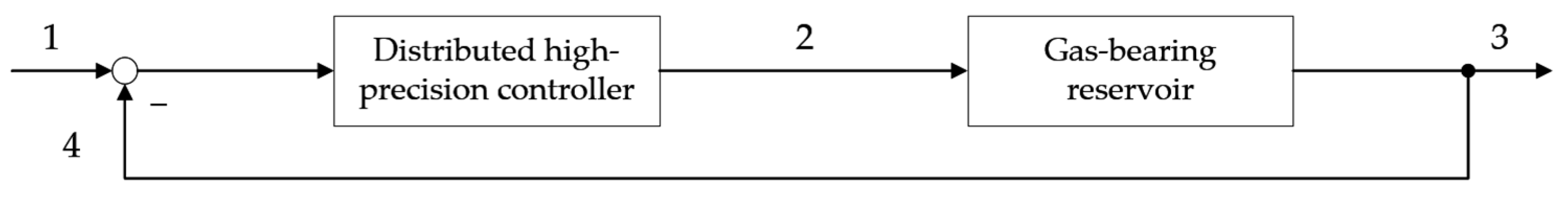
  • Gas-bearing reservoir with a complex geological structure is an object with distributed parameters since the pressure in the reservoir is distributed over the deposit (spatial coordinates), and the task of pressure field control is set;
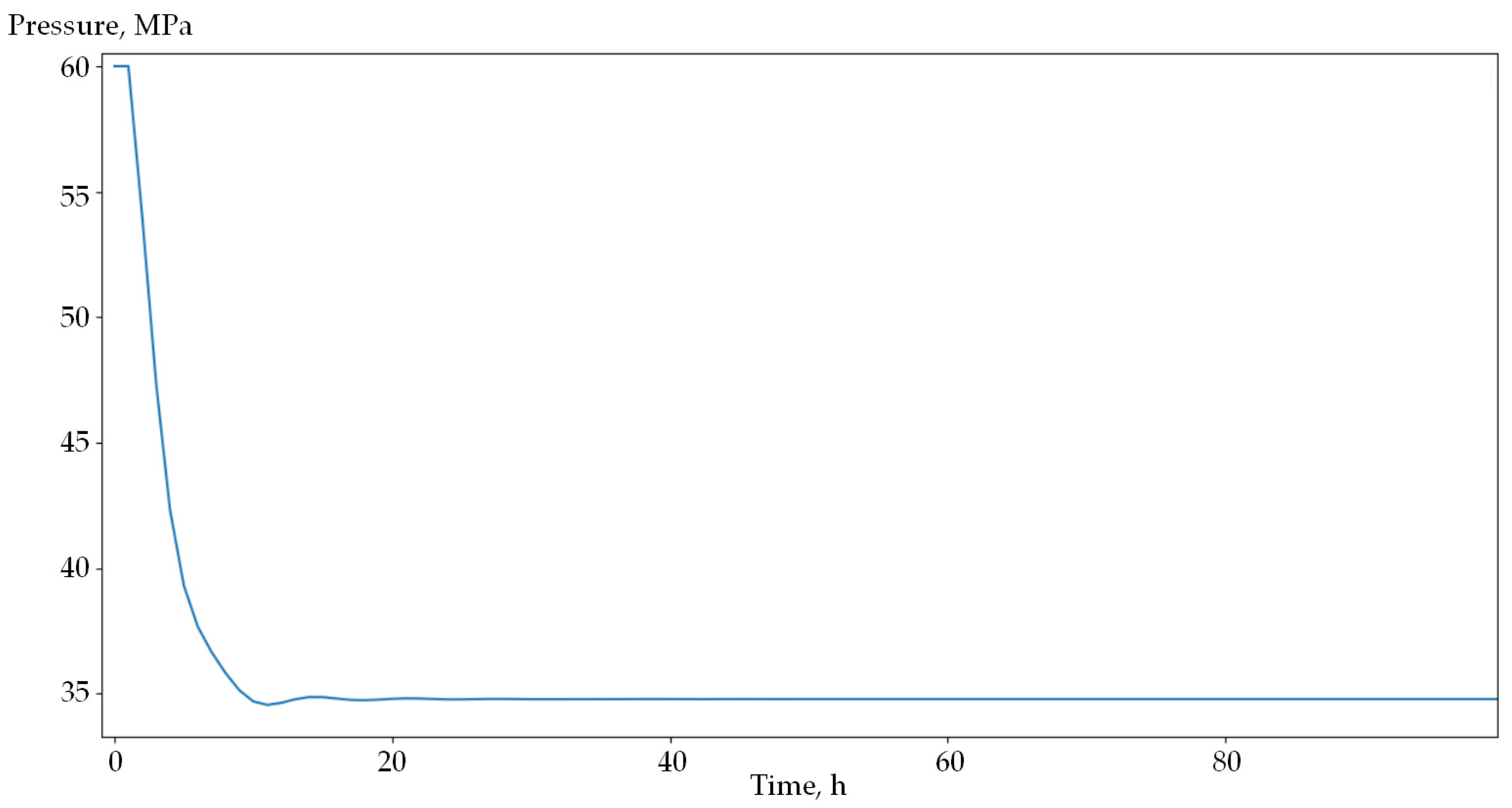
  • The synthesised pressure field control system has good quality indicators.

6. Discussion

The process of gas production in structurally complex fields has a number of peculiarities compared with the development of conventional reservoirs, which must be taken into account both in modelling the fields and in their operation [58,59,60]. Modelling a gas-bearing horizon as an object with distributed parameters in space and specified dynamic properties is proposed. This approach will make it possible to control the geometric dimensions of underbalance holes, the expansion of which leads to changes in reservoir composition and production complications, up to complete the watering of wells [61,62]. There are financial costs associated with stopping and restarting production when a well is watered out. In some cases, when a well is watered out, production cannot be restarted, and a portion of the resource will remain unextracted. At the same time, the amount of unrecovered gas increases with the growth of unevenness of pressure distribution in the reservoir. The realization of the algorithm of distributed control action formation allows for the regulation of geometric parameters of underbalance funnels at structurally complex gas fields, preventing watering and related financial costs.
The necessity to study the field as a spatially distributed object makes it necessary to apply advisory methods of controlling the processes occurring in the reservoir. For this purpose, methods of analysis and synthesis of DCS are applied. The nonlinear parabolic-type differential equation proposed by Academician Leibenzon is used as the main equation to describe the unsteady gas filtration in a porous medium. A model of the pressure distribution process based on this equation is constructed under certain assumptions. Specifically, the porosity and permeability coefficients are assumed to be constant, and the gas filtration follows the isothermal law.
A mathematical and computer model of a nine-well field control system based on the provided data has been developed, with the possibility of obtaining transient plots before and after regulation. The developed closed-loop control system belongs to distributed control systems, the main advantage of which is the possibility of realising control actions not on a specific point but on the required area at once. A conventional PID controller takes into account only the mismatch at a given point when generating a control action, while a DHC takes into account both the mismatch at a given point and mismatches at neighbouring points, which allows for improving the dynamic characteristics of the control system. Compared with multidimensional concentrated systems, distributed systems are characterised by better transient quality (less over-regulation and duration) [63]. To simulate the potential for shock wave formation in the system, additional parameters need to be incorporated into the model.
The improved algorithm of pressure field control is realized by calculating production well flow rates using Formula (31). This control algorithm can be practically implemented as a programme for a microcontroller controlling the flow rate. In this case, the initial data for the calculation of control actions are data on desired and current pressure drops in wells.
The application of distributed control systems at structurally complex gas fields affects the efficiency of the gas production system as follows:
  • Allows to regulate the geometric values of depression funnels and increases the gas and condensate recovery factor;
  • The possibility of realising control actions not on a specific point but on the required area as a whole will reduce the process of fluid backflow;
  • Allows to prevent premature watering and related financial costs.
In practice, this system can be used to analyse individual well clusters and their behaviour during operation; when it is further expanded, it will provide the results of modelling the entire field.

7. Conclusions

The paper studies the process of gas production in fields with complex geological structure and determines the main controllable variables and control actions. The possibility of implementation of distributed control systems for gas production facilities is analysed.
The following are results of the research:
  • Mathematical model of a gas-bearing reservoir as an object with distributed parameters, with given initial and boundary conditions, has been obtained;
  • A distributed system of pressure field control in a structurally complex gas field was developed;
  • It is revealed that the proposed approach will allow controlling the geometric dimensions of depression funnels;
  • The quality and performance of the synthesised system were analyzed;
  • Recommendations on the application of the proposed system in practice were formed.

Author Contributions

Conceptualisation, T.K. and P.M.; methodology, T.K. and P.M.; software, P.M.; validation, I.N.; formal analysis, P.M.; investigation, T.K. and P.M.; resources, I.N.; data curation, T.K. and P.M.; writing—original draft preparation, P.M.; writing—review and editing, T.K.; visualisation, P.M.; supervision, T.K. and P.M.; project administration, T.K.; funding acquisition, I.N. All authors have read and agreed to the published version of the manuscript.

Funding

This research received no external funding.

Data Availability Statement

The data presented in this study are available on request from the corresponding author.

Acknowledgments

The authors express their gratitude to Sergey Evgenyevich Abramkin, Technical Sciences, Department of Automation and Control Processes, St. Petersburg Electrotechnical University “LETI”, for consultations during the implementation of this work.

Conflicts of Interest

The authors declare no conflicts of interest.

References

  1. Bratskikh, D.S.; Romasheva, N.V.; Konopelko, A.Y.; Nikolaychuk, L.A. Model of Supply Chain Management in the Oil and Gas Industry Using Digital Technologies. OIJ 2024, 2024, 120–125. [Google Scholar] [CrossRef]
  2. Safiullin, R.N.; Safiullin, R.R.; Sorokin, K.V.; Kuzmin, K.A.; Rudko, V.A. Integral Assessment of Influence Mechanism of Heavy Particle Generator on Hydrocarbon Composition of Vehicles Motor Fuel. Int. J. Eng. 2024, 37, 1700–1706. [Google Scholar] [CrossRef]
  3. Litvinenko, V. The Role of Hydrocarbons in the Global Energy Agenda: The Focus on Liquefied Natural Gas. Resources 2020, 9, 59. [Google Scholar] [CrossRef]
  4. Jia, C.; Pang, X.; Song, Y. The Mechanism of Unconventional Hydrocarbon Formation: Hydrocarbon Self-Sealing and Intermolecular Forces. Pet. Explor. Dev. 2021, 48, 507–526. [Google Scholar] [CrossRef]
  5. Zhu, W.-Y.; Chen, Z.; Shang, X.-C. Multiphysical field coupling in unconventional oil and gas reservoirs. Chin. J. Eng. 2023, 45, 1045–1056. [Google Scholar] [CrossRef]
  6. Hong, L.; Jin, P.; Xiaolu, W.; Xinan, Y.; Qing, L. Analysis of Interlayer Interference and Research of Development Strategy of Multilayer Commingled Production Gas Reservoir. Energy Procedia 2012, 16, 1341–1347. [Google Scholar] [CrossRef]
  7. Jin, Z.; Zhang, J.; Tang, X. Unconventional Natural Gas Accumulation System. Nat. Gas Ind. B 2022, 9, 9–19. [Google Scholar] [CrossRef]
  8. Li, Y.; Zhou, D.-H.; Wang, W.-H.; Jiang, T.-X.; Xue, Z.-J. Development of Unconventional Gas and Technologies Adopted in China. Energy Geosci. 2020, 1, 55–68. [Google Scholar] [CrossRef]
  9. Shklyarskiy, Y.; Andreeva, I.; Sutikno, T.; Jopri, M.H. Energy Management in Hybrid Complexes Based on Wind Generation and Hydrogen Storage. Bull. Electr. Eng. Inform. 2024, 13, 1483–1494. [Google Scholar] [CrossRef]
  10. Yao, J.; Ding, Y.; Sun, H.; Fan, D.; Wang, M.; Jia, C. Productivity Analysis of Fractured Horizontal Wells in Tight Gas Reservoirs Using a Gas–Water Two-Phase Flow Model with Consideration of a Threshold Pressure Gradient. Energy Fuels 2023, 37, 8190–8198. [Google Scholar] [CrossRef]
  11. Zhukovskiy, Y.; Tsvetkov, P.; Koshenkova, A.; Skvortsov, I.; Andreeva, I.; Vorobeva, V. A Methodology for Forecasting the KPIs of a Region’s Development: Case of the Russian Arctic. Sustainability 2024, 16, 6597. [Google Scholar] [CrossRef]
  12. Prishchepa, O.; Aleksandrova, T. Study of thermodynamic processes of the Earth from the position of the genesis of hydrocarbons at great depths. J. Min. Inst. 2024, 269, 685–686. [Google Scholar]
  13. Prischepa, O.M.; Lutsky, D.S.; Kireev, S.B.; Sinitsa, N.V. Thermodynamic modelling as a basis for predicting phase states of hydrocarbon fluids at large and ultra-large depths. J. Min. Inst. 2024, 269, 815–832. [Google Scholar]
  14. Wei, M.; Zhou, J.; Duan, Y.; Long, T.; Duan, X.; Zhao, L.; Du, Y.; Hou, P. Prediction of Pressure and Temperature Profiles for Two-Phase Flow in Multilayered Gas Wells by DTS Data. Geoenergy Sci. Eng. 2024, 234, 212615. [Google Scholar] [CrossRef]
  15. Tao, X.; Okere, C.J.; Su, G.; Zheng, L. Experimental and Theoretical Evaluation of Interlayer Interference in Multi-Layer Commingled Gas Production of Tight Gas Reservoirs. J. Pet. Sci. Eng. 2022, 208, 109731. [Google Scholar] [CrossRef]
  16. Wang, C.-W.; Jia, C.-S.; Peng, X.-L.; Chen, Z.; Zhu, S.-Y.; Sun, H.-S.; Zhang, J. Effects of Wellbore Interference on Concurrent Gas Production from Multi-Layered Tight Sands: A Case Study in Eastern Ordos Basin, China. J. Pet. Sci. Eng. 2019, 179, 707–715. [Google Scholar] [CrossRef]
  17. Zhang, T.; Wang, B.-R.; Zhao, Y.-L.; Zhang, L.-H.; Qiao, X.-Y.; Zhang, L.; Guo, J.-J.; Thanh, H.V. Inter-Layer Interference for Multi-Layered Tight Gas Reservoir in the Absence and Presence of Movable Water. Pet. Sci. 2024, 21, 1751–1764. [Google Scholar] [CrossRef]
  18. Yu, Y.; Lin, L.; Zhai, C.; Chen, H.; Wang, Y.; Li, Y.; Deng, X. Impacts of Lithologic Characteristics and Diagenesis on Reservoir Quality of the 4th Member of the Upper Triassic Xujiahe Formation Tight Gas Sandstones in the Western Sichuan Basin, Southwest China. Mar. Pet. Geol. 2019, 107, 1–19. [Google Scholar] [CrossRef]
  19. Zeng, F.; Liu, B.; Zhang, C.; Zhang, G.; Gao, J.; Liu, J.; Ostadhassan, M. Accumulation and Distribution of Natural Gas Reservoir in Volcanic Active Area: A Case Study of the Cretaceous Yingcheng Formation in the Dehui Fault Depression, Songliao Basin, NE China. Geofluids 2021, 2021, e2900224. [Google Scholar] [CrossRef]
  20. Zhong, X.; Zhu, Y.; Liu, L.; Yang, H.; Li, Y.; Xie, Y.; Liu, L. The Characteristics and Influencing Factors of Permeability Stress Sensitivity of Tight Sandstone Reservoirs. J. Pet. Sci. Eng. 2020, 191, 107221. [Google Scholar] [CrossRef]
  21. Olhin, A.; Vishnyakov, A. Pore Structure and Permeability of Tight-Pore Sandstones: Quantitative Test of the Lattice–Boltzmann Method. Appl. Sci. 2023, 13, 9112. [Google Scholar] [CrossRef]
  22. Orlov, D.; Ebadi, M.; Muravleva, E.; Volkhonskiy, D.; Erofeev, A.; Savenkov, E.; Balashov, V.; Belozerov, B.; Krutko, V.; Yakimchuk, I.; et al. Different Methods of Permeability Calculation in Digital Twins of Tight Sandstones. J. Nat. Gas Sci. Eng. 2021, 87, 103750. [Google Scholar] [CrossRef]
  23. Zhao, D.; Hou, J.; Sarma, H.; Guo, W.; Liu, Y.; Xie, P.; Dou, L.; Chen, R.; Zhang, Z. Pore Throat Heterogeneity of Different Lithofacies and Diagenetic Effects in Gravelly Braided River Deposits: Implications for Understanding the Formation Process of High-Quality Reservoirs. Geoenergy Sci. Eng. 2023, 221, 111309. [Google Scholar] [CrossRef]
  24. Afagwu, C.; Alafnan, S.; Mahmoud, M.A.; Patil, S. Permeability Model for Shale and Ultra-Tight Gas Formations: Critical Insights into the Impact of Dynamic Adsorption. Energy Rep. 2021, 7, 3302–3316. [Google Scholar] [CrossRef]
  25. Ding, J.; Yan, C.; He, Y.; Wang, C. Secondary Formation Damage of Low-Pressure Layer during Commingled Production in Multilayered Tight Gas Reservoirs. Sci Rep 2019, 9, 17542. [Google Scholar] [CrossRef]
  26. Zhang, Y.; Jiang, S.; Mei, S.; Tao, Z.; Hou, S. An Experimental Investigation of Gas Permeability of a Low Permeability Sandstone under Deviatoric Loading with Loading/Unloading Cycles. Geomech. Geophys. Geo-Energy Geo-Resour. 2023, 9, 173. [Google Scholar] [CrossRef]
  27. Pszonka, J.; Godlewski, P.; Fheed, A.; Dwornik, M.; Schulz, B.; Wendorff, M. Identifica-tion and quantification of intergranular volume using SEM automated mineralogy. Mar. Pet. Geol. 2024, 162, 106708. [Google Scholar] [CrossRef]
  28. Pszonka, J.; Götze, J. Quantitative estimate of interstitial clays in sandstones using Nomarski differential interference contrast (DIC) microscopy and image analysis. J. Pet. Sci. Eng. 2018, 161, 582–589. [Google Scholar] [CrossRef]
  29. Chai, X.; Tian, L.; Dong, P.; Wang, C.; Peng, L.; Wang, H. Study on Recovery Factor and Interlayer Interference Mechanism of Multilayer Co-Production in Tight Gas Reservoir with High Heterogeneity and Multi-Pressure Systems. J. Pet. Sci. Eng. 2022, 210, 109699. [Google Scholar] [CrossRef]
  30. Gao, Y.; Jiang, R.; Xu, X.; Sun, Z.; Yuan, Z.; Ma, K.; Jiang, B.; Kang, B.; Chen, G.; Li, C. The Pressure Buildup Well Test Analysis Considering Stress Sensitivity Effect for Deepwater Composite Gas Reservoir with High Temperature and Pressure. Geofluids 2021, 2021, e5054246. [Google Scholar] [CrossRef]
  31. Zhao, Y.; Liu, X.; Zhang, L.; Tang, H.; Xiong, Y.; Guo, J.; Shan, B. Laws of Gas and Water Flow and Mechanism of Reservoir Drying in Tight Sandstone Gas Reservoirs. Nat. Gas Ind. B 2021, 8, 195–204. [Google Scholar] [CrossRef]
  32. Zhao, W.; Zhang, T.; Jia, C.; Li, X.; Wu, K.; He, M. Numerical Simulation on Natural Gas Migration and Accumulation in Sweet Spots of Tight Reservoir. J. Nat. Gas Sci. Eng. 2020, 81, 103454. [Google Scholar] [CrossRef]
  33. Chen, F.; Wang, Z.; Fu, S.; Li, A.; Zhong, J. Research on Transformation of Connate Water to Movable Water in Water-Bearing Tight Gas Reservoirs. Energies 2023, 16, 6961. [Google Scholar] [CrossRef]
  34. Bera, A.; Kumar, S.; Foroozesh, J.; Gharavi, A. Multiphysics Gas Transport in Nanoporous Unconventional Reservoirs: Challenges of Mathematical Modelling. J. Nat. Gas Sci. Eng. 2022, 103, 104649. [Google Scholar] [CrossRef]
  35. Asadulagi, M.-A.M.; Pershin, I.M.; Tsapleva, V.V. Research on Hydrolithospheric Processes Using the Results of Groundwater Inflow Testing. Water 2024, 16, 487. [Google Scholar] [CrossRef]
  36. Ilyushin, Y.; Talanov, N. Development of Methods and Models for Assessing Technical Condition of Mines and Underground Structures. Int. J. Eng. 2025, 38, 1659–1666. [Google Scholar] [CrossRef]
  37. Pervukhin, D.; Kotov, D.; Trushnikov, V. Development of a Conceptual Model for the Information and Control System of an Autonomous Underwater Vehicle for Solving Problems in the Mineral and Raw Materials Complex. Energies 2024, 17, 5916. [Google Scholar] [CrossRef]
  38. Tulyakov, T.; Afanaseva, O. Development of a Methodology for Introducing Robotic Devices for Technical Inspection of Power Lines Based on Data Mining. In Proceedings of the II International Scientific Forum on Sustainable Development and Innovation (WFSDI 2023): Conference Proceedings, Porto, Portugal, 27–28 April 2023; Institute of Digital Economics and Law LLC: Ekaterinburg, Russia, 2024; pp. 2018–2026. [Google Scholar]
  39. Boronko, E.A.; Novozhilov, I.M. Designing an Information System for Monitoring the Electromagnetic Field of a Power Plant. In Proceedings of the 2024 Conference of Young Researchers in Electrical and Electronic Engineering (ElCon), Saint Petersburg, Russia, 29–31 January 2024; pp. 331–334. [Google Scholar] [CrossRef]
  40. Romashin, D.V. Application of Artificial Intelligence to Improve the Efficiency of Monitoring and Diagnosing the Condition of Complex Technical Objects. In Proceedings of the 2024 Conference of Young Researchers in Electrical and Electronic Engineering (ElCon), Saint Petersburg, Russia, 29–31 January 2024; pp. 485–488. [Google Scholar] [CrossRef]
  41. Borodkin, V.N.; Kurchikov, A.R.; Melnikov, A.V.; Khramtsova, A.V. Formation Model and Textural Features of Rocks of the Achimov Complex in the North of Western Siberia; TyumGNGU: Tyumen, Russia, 2011; 84p. [Google Scholar]
  42. Arkhipov, V.N.; Zakharenko, V.A.; Dubrovin, A.A.V.; Starikov, M.A. Assessment of applicability of gas enhanced oil recovery methods for development of hard-to-recover reserves of objects-analogues of Achimov deposits. Expo. Oil Gas 2023, 1, 46–53. [Google Scholar] [CrossRef]
  43. Punanova, S.A. Hydrocarbon accumulations of Achimov deposits of the northern regions of Western Siberia. Expo. Oil Gas 2020, 3, 10–13. [Google Scholar] [CrossRef]
  44. Zakharov, L.A.; Martyushev, D.A.; Ponomareva, I.N. Predicting dynamic formation pressure using artificial intelligence methods. J. Min. Inst. 2022, 253, 23–32. [Google Scholar] [CrossRef]
  45. Martyushev, D.A.; Ponomareva, I.N.; Shen, W. Adaptation of transient well test results. J. Min. Inst. 2023, 264, 919–925. [Google Scholar]
  46. Abramkin, S.E.; Dushun, S.E. Implementation of Complex Control Algorithms at a Gas Production Enterprise. In Proceedings of the 2022 XXV International Conference on Soft Computing and Measurements (SCM), Saint Petersburg, Russia, 25–27 May 2022; pp. 56–59. [Google Scholar] [CrossRef]
  47. Gharavi, A.; Abbas, K.A.; Hassan, M.G.; Haddad, M.; Ghoochaninejad, H.; Alasmar, R.; Al-Saegh, S.; Yousefi, P.; Shigidi, I. Unconventional Reservoir Characterization and Formation Evaluation: A Case Study of a Tight Sandstone Reservoir in West Africa. Energies 2023, 16, 7572. [Google Scholar] [CrossRef]
  48. Lv, M.; Xue, B.; Guo, W.; Li, J.; Guan, B. Novel Calculation Method to Predict Gas–Water Two-Phase Production for the Fractured Tight-Gas Horizontal Well. J. Pet. Explor. Prod. Technol. 2024, 14, 255–269. [Google Scholar] [CrossRef]
  49. Tao, H.; Yan, L.I.U.; Jianhua, H.E.; Tairan, Y.E.; Hucheng, D.; Ruixue, L.I.; Kesai, L.I.; Jiawei, Z. Evaluation method and engineering application of in−situ stress of deep tight sandstone reservoir in the second member of Xujiahe Formation in Xiaoquan−Fenggu area, western Sichuan. Geol. China 2024, 51, 89–104. [Google Scholar] [CrossRef]
  50. Mal’Tsev, P.A.; Abramkin, S.E.; Plotnikov, A.V.; Martirosyan, K.V. A Conceptual Model of Controlled Gas Production Processes in Fields with a Complex Geological Structure. In Proceedings of the 2024 XXVII International Conference on Soft Computing and Measurements (SCM), Saint Petersburg, Russia, 22–24 May 2024; pp. 107–110. [Google Scholar] [CrossRef]
  51. Pervukhin, D.A.; Davardoost, H.; Gasimov, E.; Hawezy, A.L.J. Optimizing Multimodal Logistics in Petroleum Supply Chains Using Linear Goal Programming: A Case Study on South Pars Gas Field Development. Int. J. Eng. 2025, 38, 1909–1921. [Google Scholar] [CrossRef]
  52. Eremeeva, A.M.; Ilyushin, Y.V. Temperature Control During Storage of Raw Materials in the Process of Biodiesel Fuel Production. Inventions 2025, 10, 7. [Google Scholar] [CrossRef]
  53. Martirosyan, A.V.; Martirosyan, K.V.; Grudyaeva, E.K.; Chernyshev, A.B. Calculation of the Temperature Maximum Value Access Time at the Observation Point. In Proceedings of the 2021 IEEE Conference of Russian Young Researchers in Electrical and Electronic Engineering (ElConRus), St. Petersburg, Russia, 26–29 January 2021; pp. 1014–1018. [Google Scholar] [CrossRef]
  54. Pershin, I.M. Frequency Concept of Analysis and Synthesis of Systems with Distributed Parameters: Monograph; Ministry of Science and Higher Education of the Russian Federation, North Caucasus Federal University: Pyatigorsk, Russia, 2021; p. 171. [Google Scholar]
  55. Leibenzon, L.S. Collected Works. Volume 2. Underground Hydrogasdynamics; USSR Academy of Sciences: Moscow, Russia, 1953; 544p. [Google Scholar]
  56. Basiev, K.S.; Kochina, I.N.; Maksimov, V.M. Underground Hydromechanics: Textbook for Universities; Nedra: Moscow, Russia, 1993; p. 416. [Google Scholar]
  57. Pershin, I.M.; Tsapleva, V.V.; Malkov, A.V.; Pomelyayko, I.S. Designing a distributed well pad control system. In Proceedings of the System Synthesis and Applied Synergetics: Collection of Scientific Papers of the X All-Russian Scientific Conference, Nizhny Arkhyz Settlement, Russia, 28 September 2021; pp. 330–336. [Google Scholar] [CrossRef]
  58. Alotaibi, M.; Alotaibi, S.; Weijermars, R. Stream and Potential Functions for Transient Flow Simulations in Porous Media with Pressure-Controlled Well Systems. Fluids 2023, 8, 160. [Google Scholar] [CrossRef]
  59. Cheng, M.; Xue, W.; Guo, Z.; Hou, M.; Wang, C. Development of Large-Scale Tight Gas Sandstone Reservoirs and Recommendations for Stable Production—The Example of the Sulige Gas Field in the Ordos Basin. Sustainability 2023, 15, 9933. [Google Scholar] [CrossRef]
  60. Pan, H.; Jiang, Y.; Guo, G.; Yang, C.; Deng, H.; Zhu, X.; Zeng, Q.; Song, L.; Cao, J.; Wang, Z.; et al. Pore-Throat Structure Characteristics and Fluid Mobility Analysis of Tight Sandstone Reservoirs in Shaximiao Formation, Central Sichuan. Geol. J. 2023, 58, 4243–4256. [Google Scholar] [CrossRef]
  61. Sirota, D.D. Development of a computer model of unsteady gas filtration taking into account the inhomogeneity of the formation filtration properties. In Proceedings of the 2020 XXIII International Conference on Soft Computing and Measurements (SCM), Saint Petersburg, Russia, 27–29 May 2020; pp. 193–197. [Google Scholar]
  62. Hu, C.; Wang, F.; Liu, Y.; Zhi, J. Three-Dimensional Lattice Boltzmann Simulation of Gas-Water Transport in Tight Sandstone Porous Media: Influence of Microscopic Surface Forces. Energy Sci. Eng. 2020, 8, 1924–1940. [Google Scholar] [CrossRef]
  63. Ilyushin, Y.V.; Asadulagi, M.-A.M. Development of a Distributed Control System for the Hydrodynamic Processes of Aquifers, Taking into Account Stochastic Disturbing Factors. Water 2023, 15, 770. [Google Scholar] [CrossRef]
Figure 1. Paleogeomorphological scheme of the formation of the Achimov deposits of Trans-Western Siberia [41] (1—deep-water clay-bituminous sediments; 2—river; 3—river delta; 4—coastal lakes; 5—land; 6—coastline; 7—coastal-shallow-water zone; 8—bars of the open sea; 9—edge of the coastal-shallow-water zone; 10—planar washout; 11—channels of turbidity flows; 12—landslides; 13—sandy-silty cones of turbidity flow outlets (turbidites); 14—distal hemipelagic silts; 15—sand waves (‘riffles’)).
Asi 08 00051 g001
Figure 2. Layered model of a gas-bearing reservoir ( x L x, y L y and z L z are the geometric dimensions of the modelled system; 1–9 are the numbers of blocks).
Asi 08 00051 g002
Figure 3. Graph of the transient process by mode 1.
Asi 08 00051 g003
Figure 4. Graph of the transient process by mode 3.
Asi 08 00051 g004
Figure 5. Approximation of the time constant by mode 1 (the blue line indicates pressure dynamics; the black line denotes the approximation of the time constant T1).
Asi 08 00051 g005
Figure 6. Approximation of the time constant by mode 3 (the blue line indicates pressure dynamics; the black line denotes the approximation of the time constant T3).
Asi 08 00051 g006
Figure 7. Structural diagram of a closed-loop system (1—set pressure value; 2—controlling influence on the object; 3—desired pressure at the system output; 4—mismatch error).
Asi 08 00051 g007
Figure 8. Transients taking into account the regulating influence.
Asi 08 00051 g008
Disclaimer/Publisher’s Note: The statements, opinions and data contained in all publications are solely those of the individual author(s) and contributor(s) and not of MDPI and/or the editor(s). MDPI and/or the editor(s) disclaim responsibility for any injury to people or property resulting from any ideas, methods, instructions or products referred to in the content.

