Article

Design and Experimental Validation of a Battery/Supercapacitor Hybrid Energy Storage System Based on an Adaptive LQG Controller

by
Jhoan Alejandro Montenegro-Oviedo
1,
Carlos Andres Ramos-Paja
2,
Martha Lucia Orozco-Gutierrez
1,*,
Edinson Franco-Mejía
1 and
Sergio Ignacio Serna-Garcés
3
1
Escuela de Ingeniería Eléctrica y Electrónica, Universidad del Valle, Cali 760042, Colombia
2
Facultad de Minas, Universidad Nacional de Colombia, Medellin 050041, Colombia
3
Departamento de Electrónica y Telecomunicaciones, Instituto Tecnológico Metropolitano, Medellin 050013, Colombia
*
Author to whom correspondence should be addressed.
Appl. Syst. Innov. 2025, 8(1), 1; https://doi.org/10.3390/asi8010001
Submission received: 21 November 2024 / Revised: 17 December 2024 / Accepted: 23 December 2024 / Published: 25 December 2024

Abstract

:
Hybrid energy storage systems (HESSs) are essential for adopting sustainable energy sources. HESSs combine complementary storage technologies, such as batteries and supercapacitors, to optimize efficiency, grid stability, and demand management. This work proposes a semi-active HESS formed by a battery connected to the DC bus and a supercapacitor managed by a Sepic/Zeta converter, which has the aim of avoiding high-frequency variations in the battery current on any operation condition. The converter control structure is formed by an LQG controller, an optimal state observer, and an adaptive strategy to ensure the correct controller operation in any condition: step-up, step-down, and unitary gain. This adaptive LQG controller consists of two control loops, an internal current loop and an external voltage loop, which use only two sensors. Compared with classical PI and LQG controllers, the adaptive LQG solution exhibits a better performance in all operation modes, up to 68% better than the LQG controller and up to 84% better than the PI controller. Therefore, the control strategy proposed for this HESS provides a fast-tracking of DC-bus current, driving the high-frequency component to the supercapacitor and the low-frequency component to the battery. Thus, fast changes in the battery power are avoided, reducing the degradation. Finally, the system adaptability to changes up to 67% in the operation range are experimentally tested, and the implementation of the control system using commercial hardware is verified.

1. Introduction

Energy storage systems (ESSs) must to be efficient, reliable, and cost-effective to supply the requirements of microgrids (MGs) [1,2], electrical vehicles (EVs) [3,4,5], and renewable energy applications [6,7], among others. These requirements have stimulated the emergence of hybrid energy storage systems (HESSs) characterized by the cooperative operation of two or more energy storage technologies [8]. The main feature of an HESS is the complementary condition of the ESSs in terms of power and energy density [8]; e.g., one or several ESSs should provide energy by hours or days, while other ESSs have to provide a high amount of instantaneous power with a discharge time in the order of seconds or minutes. These characteristics allow the HESS to be used for stabilization purposes, for example, when high power and fast response are required; in this case, the HESS should include supercapacitors (SC) or flywheels, as discussed in [8]. Another application is the EV, where the HESS must have a high-energy capacity; therefore, batteries must be included [4,8,9]. Moreover, other applications could profit from HESSs: integration of sources based on renewable energy [7,10], power quality improvement [11,12,13,14,15], uninterrupted power supply (UPS), and public transport vehicles powered by electricity [16]. Some commercial products provide HESS systems encapsulated as a single device; for example, CRE New Energy Technology offers a battery–ultracapacitor hybrid energy storage unit with high peak currents [17], which is designed to be used as a battery replacement in buck-up units. The same company recently developed a new scalable hybrid supercapacitor–battery unit designed for industrial environments [18], in particular for driving motors. However, these units have a close architecture, hence it is not possible to analyze the performance in battery protection, peak current regulation, or system stability.
Three major types of HESSs have been developed: passive, semi-active, and fully active [19,20]. Passive HESSs are highly efficient and cheap since they do not include power converters, but passive HESSs are uncontrolled systems whose behavior depends on the ESS parameters. In semi-active HESSs, an ESS is connected to the DC bus, while a DC/DC bidirectional converter interfaces the DC bus with other ESSs. This configuration offers a good trade-off between cost and performance. Finally, the fully active topology decouples all ESSs from the DC bus using power converters, thus achieving the maximum benefit from the ESSs but at the expense of complex controllers; moreover, this topology is expensive and has low efficiency in contrast with the other two HESS types.
There are multiple works reported in the literature dealing with HESS controllers. For example, in [21] is reported a fully active HESS formed by a battery and an SC, which are interfaced with the DC bus using bidirectional boost converters. In that work, an equalization algorithm based on model predictive control (MPC) governs the converters, where the MPC considers the state of charge (SoC) of both battery and SC. Moreover, classical PI controllers regulate the voltage and current of the boost converters following a second-level droop control. Finally, that system is validated with simulation and experimental tests.
Another fully active HESS is reported in [22], which is formed by a battery, an SC, and a fuel cell, connected to a DC bus. This HESS is regulated using a central super-twisting sliding mode control, where the current reference is given by an energy management unit based on fuzzy logic. The primary control is applied to an unidirectional boost converter and two bidirectional boost converters, and the controller performance is verified using Matlab/Simulink and hardware-in-the-loop (HIL) emulation on a C2000 Delfino. There is no experimental validation on a real power system.
Similar to [22], the work reported in [23] proposes a fully active HESS formed by three power sources: a battery, an SC, and a PV panel array. The interface with the DC bus is performed with a boost converter and two bidirectional boost converters, which are regulated using classical PI controllers. This HESS has a power management strategy designed to reduce the dynamic stress of the battery, provide a stable DC voltage, prevent a deep battery discharge, and enhance the overall efficiency of the system. The tuning process of these PI controllers is performed with different methods: pole placement, linear matrix inequalities (LMIs), particle swarm optimization (PSO), and genetic algorithm (GA). Then, the performances of the PI controllers, under several scenarios and with different tuning methods, are compared in Matlab/Simulink only.
Simulations and experimental comparisons of the three HESS types are reported in [6]. The tested HESSs are formed by a PV panel, a battery, and an SC using bidirectional boost converters, where the primary controllers are classical PI, with reference currents obtained from a second-level power flow control.
Another HESS formed by batteries and lithium-ion capacitors (LiCs) is reported in [24], where the semi-active configuration is used. In this case, the battery is connected to a DC bus, and the LiC current is controlled by a non-specified bidirectional DC/DC converter. A power flow controller in the second level sets the battery current, which is regulated using a classical PI acting on the power converter. Finally, the validation of this HESS is carried out using an advanced vehicle simulation platform.
Similar to the previous work, in [25] is used a non-specified bidirectional DC/DC converter to form a semi-active HESS based on a battery and a supercapacitor. This HESS is controlled using a hysteresis control algorithm, where its reference is generated by an optimizer based on both fuzzy logic and model predictive controllers. Unfortunately, the dynamic performance of the controllers is not evaluated. Another hysteresis control for HESS is reported in [26], where the battery SoC and the supercapacitor SoV (state of voltage) are used to control a bidirectional boost converter. This solution reduces the battery discharge percentage and improves the system’s efficiency by stabilizing the DC bus voltage.
Typically, the HESS control strategy consists of distributing the power between the storage devices, and thus it is mainly an energy management system (EMS). A well-designed control strategy will use the complementary features of the ESS forming the HESS, allocating the low-frequency power demand to the device of high energy density. Similarly, the high-power density device must to attend the short-time peaks, i.e., the high-frequency power profile. There are multiple EMSs for HESSs reported in the literature, which can be divided into three main categories: rule-based control strategies, optimization-based control strategies, and intelligence-based control strategies [27].
In summary, the previous literature review shows that bidirectional boost converters are commonly used in HESS systems to connect the supercapacitor with the battery or DC bus [6,21,22,23,26]. This selection is based on the simplicity of the bidirectional boost topology; however, this topology introduces two major limitations: first, the supercapacitor voltage must be lower than the battery or DC bus voltage, which limits the commercial supercapacitors and batteries that can be used to form the HESS; and, second, the supercapacitor boost converter provides a discontinuous current to the battery, which introduces high-frequency current harmonics that could produce heating and damages. The literature revision also shows that classical PI controllers are widely used to regulate the supercapacitor converter [6,21,23,24], which must be designed around a particular operation condition. Therefore, such a solution makes it impossible to ensure the desired performance (and even global stability) in a wide operation range. Finally, several solutions are only tested with simulators or emulators [22,23,24,26], which prevents the evaluation of real operation conditions such as parasitic losses, bandwidth limitation, and inductor saturation, among others. This paper faces the previous drawbacks by designing a semi-active supercapacitor/battery hybrid energy storage system based on a bidirectional Sepic/Zeta DC/DC converter, which interfaces the SC and the battery/DC bus, as observed in Figure 1. This connection enables the indirect control of the battery current, thus avoiding high-frequency transients to the battery. The main contributions of the the proposed solution are:
  • The power stage (Sepic/Zeta converter) has the advantage of connecting devices to the DC bus with any voltage condition (lower, equal, or higher than the ESS voltage).
  • The Sepic side of the converter is connected to the battery/DC bus, which guarantees a continuous current (non-pulsating waveform) and prevents high-frequency transients in the battery.
  • A gain-scheduling approach is used to design the proposed LQG-FF controller, which adapts the controller parameters to the system’s operating condition (step-down/step-up or unitary conversion ratio). This real-time adjustment makes the system highly adaptive and efficient, thus it provides a robust and flexible solution with the desired transient performance.
The rest of the paper is organized as follows. Section 2 reports the power stage model, which is based on a bidirectional Sepic/Zeta converter. Then, a control-oriented model is obtained from the switched model, and it is validated against both the circuital and switched models through frequency response analysis. In Section 3, a feedforward/optimal Linear Quadratic Gaussian (LQG-FF) controller, with adaptive parameters, is proposed. This controller ensures that the high-frequency component of the load current is provided by the supercapacitor, and hence the reference current of the Sepic/Zeta converter is calculated using a high-pass filter. Such a control approach guarantees that the battery will only deal with low-frequency current components. Section 4 reports Matlab/Simulink simulations of the HESS in the three operation modes: step-up, step-down, and unitary gain; in the same way, Section 5 analyzes the results of the experimental tests for the same application cases. The conclusions are presented in Section 6.

2. Modeling of the Power Stage

This section presents the power stage of the proposed solution, providing also the mathematical model needed for the control design.

2.1. Circuital Interface

The electrical scheme of the proposed hybrid storage system, formed by a battery and a supercapacitor, is illustrated in Figure 2. This power stage was designed using the Sepic topology, which was selected to enable the energy transmission for any voltage relation between the battery and the supercapacitor. In the electrical scheme, the supercapacitor is modeled with the capacitance ( C s c ) and the parasitic resistance ( R s c ), while the battery is modeled by the series connection of the voltage source ( v b o c ) and the battery resistance ( R b ). The load connected to the hybrid source is modeled by the current source ( i d c ) and the voltage imposed to the load is named v d c . The elements of the Sepic converter are the inductors ( L 1 and L 2 ), the capacitor ( C i ), and the MOSFETs ( M 1 and M 2 ). Moreover, the electrical scheme also considers the parasitic resistances of both the MOSFETs ( R o n ) and inductors ( R L 1 , R L 2 ).
The load modeled by a current source ( i d c ) makes possible to take into account discharge (positive i d c ), charge (negative i d c ), and stand-by (null i d c ) conditions. In addition, the battery current ( i b ) is the result of the load current ( i d c ) and the Sepic current ( i s z ).
The main objective of this power interface is to control, in an indirect way, the battery current ( i b ) to avoid high-frequency transients. This process requires the measurement of both the load current and the Sepic output current ( i s z ), where the Sepic converter provides the high-frequency transients required by the load.

2.2. Control-Oriented Model

This section derives a mathematical model for the hybrid power system of Figure 2, which is aimed at supporting the controller design. The first step is to analyze the power system when the activation signal of the MOSFETs is u = 1 ( u ¯ = 0 ), thus M 1 is ON and M 2 is OFF, as illustrated in Figure 3.
The resulting differential equations for this operation condition, for both the inductors and capacitors, are:
d i L 1 d t = v s c o ( i L 1 + i L 2 ) · ( R o n + R s c ) i L 1 · R L 1 L 1
d i L 2 d t = v s c o + v c i ( i L 1 + i L 2 ) · ( R o n + R s c ) i L 2 · R L 2 + ( i d c i L 2 ) · R b v b o c L 2
d v c i d t = i L 2 C i
d v s c d t = i L 1 i L 2 C s c
The second step is to analyze the power system when the activation signal of the MOSFETs is u = 0 ( u ¯ = 1 ), thus M 1 is OFF and M 2 is ON, as illustrated in Figure 4. Then, the resulting differential equations of this new condition are given in Equations (5)–(8).
d i L 1 d t = v c i ( i L 1 + i L 2 ) · R o n i L 1 · R L 1 L 1
d i L 2 d t = ( i L 1 + i L 2 ) · R o n i L 2 · R L 2 + ( i d c i L 2 ) · R b v b o c L 2
d v c i d t = i L 1 C i
d v s c d t = 0
The switched model of this power system is obtained by combining each pair of the previous differential equations using the activation signal (u) and its complement ( u ¯ ) as follows:
d i L 1 d t = v s c · u v c i · u ¯ ( i L 1 + i L 2 ) · ( R o n + R s c · u ) i L 1 · R L 1 L 1
d i L 2 d t = ( v s c + v c i ) · u ( i L 1 + i L 2 ) · ( R o n + R s c · u ) L 2 + i L 2 · R L 2 + ( i d c i L 2 ) · R b v b o c L 2
d v c i d t = i L 1 · u ¯ i L 2 · u C i
d v s c d t = ( i L 1 i L 2 ) · u C s c
A linearized representation of the previous model is obtained to perform the adaptive controller design. This linearization process is based on the averaging method, in which all the switched differential Equations (9)–(12) are averaged within the switching period T = 1 / F , where F is the switching frequency. Taking into account that the duty cycle is d = 1 / T 0 T u d t , the averaged differential equations have u replaced by d. The linearized model is developed in small-signal conditions, where x ˜ , d ˜ , and y ˜ are the small-signal variations of the state vector, input vector, and output, respectively. Then, the model states are defined as follows:
x ˜ 1 = i ˜ L 1 x ˜ 2 = i ˜ L 2 x ˜ 3 = v ˜ c i x ˜ 4 = v ˜ s c
Based on Equation (13), the small-signal state vector is x ˜ = x ˜ 1 x ˜ 2 x ˜ 3 x ˜ 4 T . Finally, the state-space representation of the small-signal model is given in Equation (14), where A m and B m are matrices evaluated in steady-state conditions around a given operation point.
x ˜ ˙ = R o n + R s c · d e + R L 1 L 1 R o n + R s c · d e L 1 ( 1 d e ) L 1 d e L 1 R o n + R s c · d e L 2 R o n + R s c · d e + R L 2 + R b L 2 d e L 2 d e L 2 ( 1 d e ) C i d e C i 0 0 d e C s c d e C s c 0 0 A m · x ˜ + v s c + v c i e ( i L 1 e + i L 2 e ) · R s c L 1 v s c + v c i e ( i L 1 e + i L 2 e ) · R s c L 2 i L 1 e i L 2 e C i i L 1 e i L 2 e C s c B m · d ˜
This model will be used in Section 3 to develop the adaptive controller for the hybrid storage system. In order to test the model accuracy, the output of the model is defined as y ˜ = v ˜ s c :
y ˜ = 0 0 0 1 C m · x ˜
The previous output definition is used to obtain the frequency response of the state-space model, which is compared with the frequency responses of both the switched model given in (9)–(12) and a circuital simulation performed in MATLAB. Figure 5 shows the three bode diagrams, where the switched model reproduces with high accuracy the frequency response of the circuital model; however, a small phase deviation at high frequencies is caused by the proximity to the switching frequency, which introduces computation errors since the switched model is calculated with the Euler method, while the circuital model is processed with a variable simulation step. The linear model also reproduces the circuital model behavior with high accuracy, but with a small gain deviation at the resonance frequency (between 200 Hz and 300 Hz), which is caused by the linearization process around a single operation condition. In any case, the linear model provides a satisfactory frequency representation of the more complex and nonlinear models. These results put into evidence the correctness of the switched differential Equations (9)–(12), and confirms the usability of the linear model for control systems design.

3. Adaptive LQG-FF Current–Voltage Controller

The control of the proposed HESS has the main objective of avoiding high-frequency variations on the battery current ( i b ) on any operation condition, i.e., in charge and discharge modes. Moreover, the controller must guarantee the stability conditions on the overall operation range; that is, under any voltage ratio between the battery and supercapacitor (i.e., buck mode, boost mode, or unitary gain).
Therefore, the controller must to impose a fast output current ( i s z ) in the converter to provide the fast variations of the bus current ( i d c ). The compensation is performed with a disturbance rejection controller, in particular a feed-forward controller. The system model given in Equation (14) has matrices A m and B m 
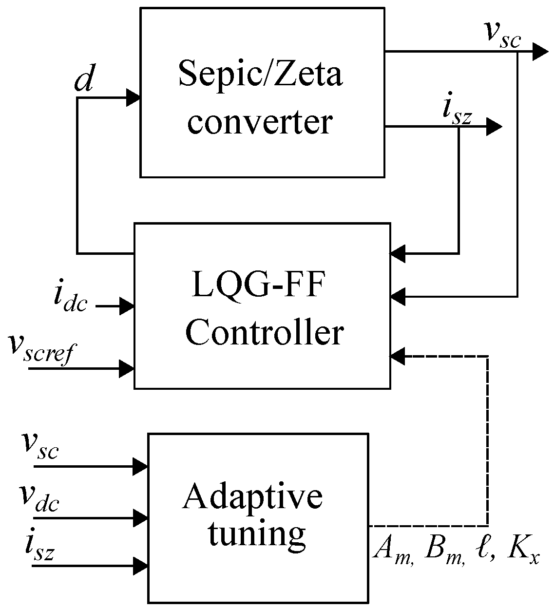
that change in function of the operation point, and hence it is a system with variable parameters. Controlling this system over a wide operation range requires an adaptive algorithm; in this paper a feed-forward/optimal Linear Quadratic Gaussian (LQG) controller, with parameters adaptation, is designed. The general structure of the control strategy is shown in Figure 6, where high-frequency components of the load current ( i d c ) are sensed and feed back through a high-pass filter (HPF) block. Moreover, this structure has an inner loop to provide the high-frequency current components, and an external loop to regulate the DC bus voltage.
The control system design is divided into three stages. First, the design of the LQG controller; second, the design of an optimal observer to estimate the states; and, third, the design of the adaptive parameters function to adjust the controller to any operation point.
First, the optimal LQG approach was selected to track the current reference (generated by the HPF), to regulate the voltage ( v s c ) and to ensure stability conditions. The target of an optimal trajectory system is to design a controller that ensures a close tracking of a specified time-varying trajectory ( z ( t ) ) [28]. For the HESS model, the anticipative input signals (d) and the non-anticipative disturbance input signals are used, which correspond to the high-frequency components of the load (bus) current ( i d c ). The control law for the optimal trajectory tracking consists of a feed-forward controller and a feedback controller, which are designed to minimize a performance index that includes penalties on the tracking errors (z) and the control energy (d):
J = 0 t f 1 2 · ( z ˜ T Q z + r d ˜ 2 ) · d t , r R > 0 , Q R 5 x 5 > 0
In the previous expression, z ˜ is the extended state vector, which includes the error integral, named x ˜ i . Then, the state feedback law (K) is defined in Equation (17), and the extended system is defined in Equation (18).
d ˜ = K · z ˜ = K x K i · x ˜ x ˜ i
z ˜ ˙ = x ˜ ˙ x ˜ ˙ i = A m 0 C m 0 A w · x ˜ x ˜ i z ˜ + B m 0 B w · d ˜
Then, the optimal value for the control signal d ˜ * is calculated using the Hamiltonian matrix [29], as given in (19).
d ˜ * = r 1 · B w T · S m · z ˜ = K · z ˜
K = r 1 · B w T · S m
Next, the S m matrix must be solved from the Riccati differential equation given in (21).
Q + A w T · S m + S m · A w S m · B w · r 1 · B w T · S m + S ˙ m = 0
In addition, to ensure null steady-state errors, integrators are added to both output current and bus voltage errors.
On the other hand, to ensure a high reference tracking speed for the current loop, a feed-forward control is added, which ensures a fast action on the control signal d in response to changes on the bus current. In this way, the supercapacitor supplies the high-frequency variations of the DC bus, while the battery supports only the frequencies below the cutoff frequency of the high-pass filter.
In addition to the current control, an external cascade loop is added to regulate the supercapacitor voltage ( v s c ). In this way, the state of charge of the supercapacitor, in steady-state, is regulated at a level that ensures the same capacity to deliver and absorb energy.

3.1. State Observer

A state observer was designed to reduce the number of sensing elements; in this application, it enables us to process the control strategy only measuring the current ( i s z ), as shown in Figure 7. In addition, the observer needs the duty cycle (d), which is known. The output of the observer is the vector of estimated states, which are the inductor currents and capacitor voltages; these were defined in Equations (13) and (14).
For the small-signal model obtained in Equations (14) and (15), and the feedback state law defined in (20) [30], the linear state observer is formalized as follows:
x ^ ˙ = A m · x ^ + B m · d · ( y y ^ ) = ( A m + · C m ) · x ^ + B m · d · y
y ^ = C m · x ^
where y corresponds to i s z , as shown in Figure 7.
In Equation (22), the observer gain vector () defines the dynamic behavior of the error estimation, ensuring the observer convergence to the system states. This observer gain () is calculated solving an optimization problem to ensure two characteristics: the best estimation of the states, and minimizing the effect of measurement noise in i s z . Similarly to the feedback state vector (K), the observer gain vector () in Equation (24) is calculated by solving the Riccati differential equation given in (25) [29]; here, S o corresponds to the optimal error covariance matrix of the state observer, and γ is a scalar to adjust the convergence speed of the observer states [31].
= S o · C m T · γ
A m · S o + S o · A m T S o · C m T · γ 1 · C m · S o + B m · B m T + S o ˙ = 0

3.2. Structure of the LQG Current–Voltage Controller

Figure 8 shows the designed control structure formed by the state observer, the state feedback, the internal current loop with feed-forward control, the filtering block (HPF), and finally the external voltage loop. In this diagram, the variables include both the stable state and small-signal responses provided by the previous dynamic model.

3.3. Adaptive Gain-Scheduling Parameters for the LQG-FF Controller

Due to the nonlinear characteristics of the Sepic converter, a method to adjust the controller parameters under any operation condition was designed. The adopted approach is named Gain-scheduling, which is a popular nonlinear technique widely used in aerospace and process control [32]. This method requires the calculation of the state feedback vector and the observer parameters, solving offline the Riccati differential equation for each operating point ( v s c and v b combinations). Subsequently, intermediate operating values are calculated through a linear function; in this way, the variation of the state feedback vector and the observer gain vector are calculated; these functions must be implemented in a real-time control device.
The complete control structure, which includes the integration of the different control blocks previously described, is shown in Figure 9. In this solution, the model parameters are adjusted depending on the operating point, thus updating matrices A m , B m , , K x ; and four signals are measured: the currents i s z and i d c , and the voltages V s c and V d c .
A reduction in the SoC of a battery decreases the terminal’s voltage [33]; similarly, the energy stored in the supercapacitor is calculated as C s c · v s c 2 / 2 , and hence the supercapacitor SoC is also reduced when the voltage is decreased. Therefore, the adaptive gain-scheduling method used in this work ensures the correct parameters for any SoC and voltage condition in the battery and supercapacitor.

3.4. Selection of the Supercapacitor

The capacitance value is calculated to avoid high variations in the supercapacitor state of charge, which depends on the energy absorbed or delivered in the different operating conditions. The current of the supercapacitor corresponds to the high-frequency component of the DC bus current, which is represented by the following equation considering a step change on the DC bus current:
i s c ( s ) = Δ i d c m a x · s s + 2 · π · f c · 1 s
In Equation (26), Δ i d c m a x represents the magnitude of the DC bus current perturbation, and f c corresponds to the cut frequency (in Hz) of the filter HPF used in the controller. The time representation of (26), obtained from the inverse Laplace transformation, is:
i s c ( t ) = Δ i d c m a x · e 2 π · f c · t
Equation (28) reports the voltage variation in the supercapacitor caused by the previous current perturbation, where t s corresponds to the stabilization time of the supercapacitor current for a unitary step perturbation in the bus current.
Δ v s c = 1 C s c 0 t s i s c ( t ) · d t
Then, solving Equation (28) leads to the minimum value of C s c needed to ensure a maximum voltage deviation ( Δ v s c ):
C s c m i n = Δ i d c m a x Δ v s c · 2 π · f c · ( 1 e 4 )
A security factor of 50 % is introduced to take into account parametric tolerances in the electronic components and parasitic losses in the cables, among other unpredicted conditions, leading to the final supercapacitor selection range:
C s c 1.5 · C s c m i n

4. Design Example and Simulation Results

This section illustrates the design process of the proposed solution, where the performance of the proposed HESS is evaluated using detailed circuital simulations. The test-bed consists of a DC microgrid connected to a 12 V battery and a supercapacitor with a rated voltage of 16 V. This proof-of-concept HESS has a rated power of 40 W, where the Sepic/Zeta converter has a switching frequency F = 40 kHz, with inductors L 1 = L 2 = 680 μ H and an intermediate capacitor C i = 330 μ F. Finally, this design example considers load (bus) current transients up to 3 A, and hence the i d c range is [ 3 , 3 ] A.
The supercapacitor design is preformed using Equations (29) and (30) with a maximum bus current change Δ i d c m a x = 6 A. Moreover, the supercapacitor is designed to ensure a maximum voltage change of 1 % and a cut frequency f c = 0.5 Hz of the HPF, which results in a minimum value of the supercapacitor equal to 34.15 F. Due to the commercial availability and cost, the supercapacitor BMOD0058E016C02 [34] is used, which has a capacitance equal to 58 F, thus fulfilling expression (30).Table 1 summarizes the parameters of this design example.
The matrices A m and B m of the space-state model are obtained offline by using Equation (14). The parameters of these matrices are calculated for different operating points resulting from variations on the supercapacitor voltage ( v s c ). Then, the K and parameters of the controller are calculated using the LQR function from Matlab 2024b® for all the space-state systems. For any other operating point, the adaptive gain-scheduling strategy determines the control parameters using a linear interpolation from the parameters previously calculated.
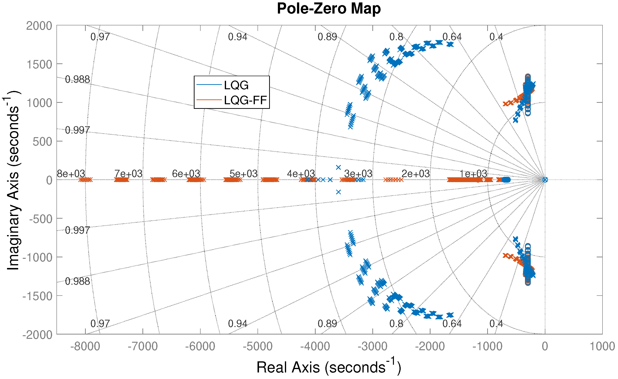
Figure 10 shows a pole-zero map to verify the close-loop stability of the system for different voltage (and SoC) conditions of both battery and supercapacitor. In this analysis, multiple operating points are simulated considering variations of 2 V for v d c and v s c , thus covering all the operation range. It is observed that the pole-zero points for all operating points are in the left side of the S-plane, which confirms the system stability.
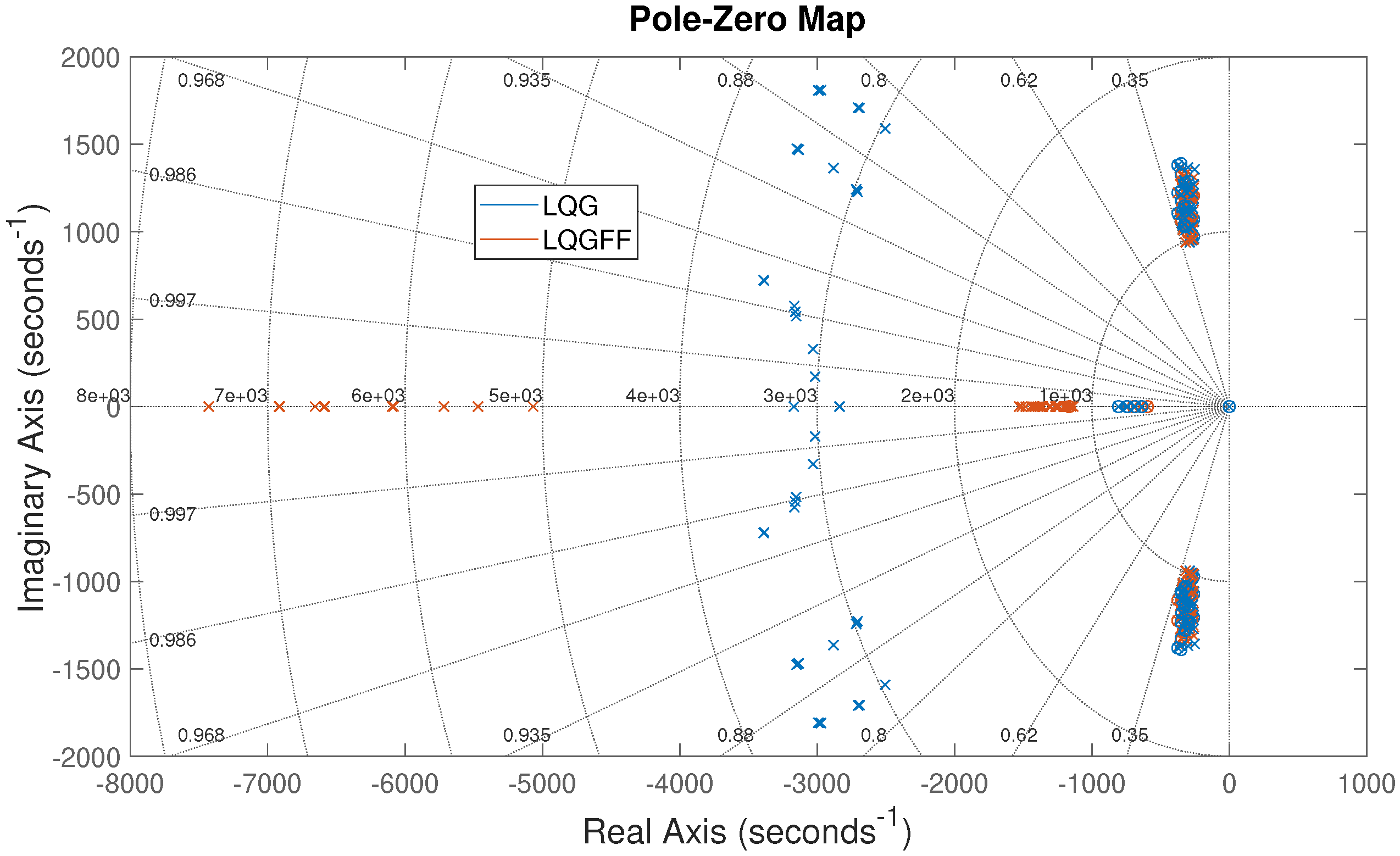
On the other hand, Figure 11 shows the pole-zero map considering parametric variations on the converter elements, e.g., due to parametric tolerances. This analysis considers a tolerance of 15 % for the inductors and 20 % for the capacitors, and the results demonstrate that tolerances in the circuit components do not represent a risk for the system stability.
Then, the performance of both the HESS and the adaptive control system are evaluated in terms of current reference tracking and capacitor voltage regulation. The HESS is implemented using detailed circuital models in Simulink® from Matlab®. The main objective of the HESS is to provide the high-frequency current perturbations of the DC bus, which could be produced by power variations among loads and sources connected to the bus. In this way, the battery only provides the low-frequency current variations. Moreover, in real operation conditions, the supercapacitor voltage could be lower, equal to, or higher than the DC bus voltage, which implies that the power converter must operate in buck mode, boost mode, or at unitary gain. The following subsections report the simulation results in these different operating conditions.

4.1. Tracking of the Current Reference

The current reference tracking evaluates the ability of the HESS to provide the high-frequency transients using the supercapacitor. In addition to the adaptive LQG-feed-forward controller (LQG-FF) proposed in this paper, this test also includes two traditional control strategies for comparison purposes: the classical PI controller widely adopted in literature for this same application, and the classical LQG controller.
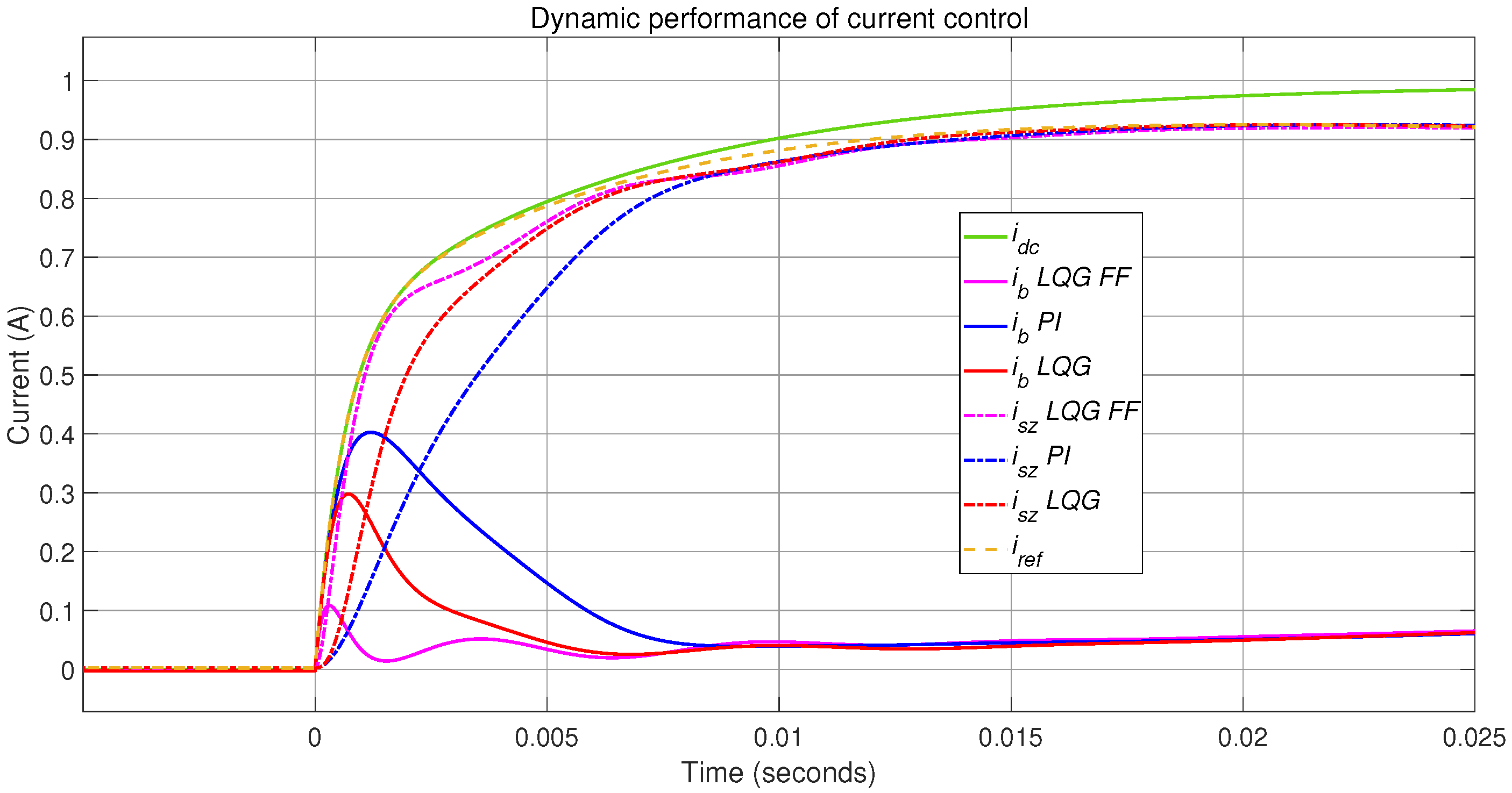
The tests consider step perturbations on the DC bus current ( i d c ) from 0 A to 1 A. In these conditions, the battery voltage ( v d c ) is equal to 12 V, and three levels of supercapacitor voltage ( v s c ) are considered: 9 V (buck mode), 12 V (unitary gain), and 15 V (boost mode). The results are shown in Figure 12 (boost mode), Figure 13 (unitary gain) and Figure 14 (buck mode). In these simulations, the proposed LQG-FF controller exhibits the faster tracking of the reference ( i r e f ) (yellow/dashed line), thus imposing an output current profile ( i s z ) (magenta/dashed line) close to the desired waveform ( i r e f ). In addition, the transitory peak occurring in the battery current (magenta/solid line) is the lowest one in comparison with the other control systems, where the classical PI controller exhibits the worst performance in terms of maximum overshoot and reference tracking. This is expected since the parameters of the proposed LQG-FF controller are adapted in real time to ensure the tracking of the high-frequency reference, and hence lower oscillations in the battery current occur. The classical controllers (PI and LQG) were designed for a particular condition in the middle of the operation range, and hence these controllers were not adapted during the transient conditions.
The Root-Mean-Square-Error (RMSE) between i r e f and i s z is calculated during the transitory response to be used as a performance indicator. The RMSE for the three controllers are shown in Table 2, where different operating points are tested. In this test, the proposed LQG-FF controller provides the best performance in the complete range of v s c , and the PI controller exhibits the worst behavior. The last two columns of the table show the error comparison between the proposed LQG-FF solution and the two classical approaches, where the LQG-FF controller provides a fraction of the error introduced by the other two solutions.
The controller’s performances for longer profiles were evaluated considering a load current that forces both charge ( i d c < 0 ) and discharge ( i d c > 0 ) conditions. The tests results are reported in Figure 15, Figure 16 and Figure 17, where the DC bus current ( i d c ) is presented in green color. The bus current starts at 0 A, and after 4 s the DC bus current is increased to 1 A, and thus the battery enters discharging mode ( i d c > 0 A) and the supercapacitor provides the fast current transient to the DC bus using i s z . At 10 s, the DC bus current is decreased to 0 A, and in this case the supercapacitor absorbs the negative current transient. At 16 s, the DC bus current is changed to 1 A, and hence the battery enters charging mode ( i d c < 0 A) and the supercapacitor absorbs the negative current transient. Finally, the test ends by driving the DC bus current to zero, which sets the battery into stand-by mode ( i d c = 0 A). For all bus current perturbations, the battery current reaches the stable condition after 1 s with null steady-stable error. In addition, the test confirm that the supercapacitor provides or absorbs the high-frequency transients, thus ensuring low stress for the battery.
The simulations demonstrate the correct behavior of both the HESS and control system, where the supercapacitor provides or absorbs the high-frequency current transients of the DC bus. The simulations also show the correct adaptability of the control system to changes on the voltages (buck, boost, unitary gain), and at different operating conditions of the battery (charge, discharge, stand-by), hence ensuring the stability of the system and avoiding the saturation of the duty cycle in the power converter.

4.2. Voltage Regulation

In any HESS, the supercapacitor is submitted to charge and discharging conditions. However, the supercapacitor charge (which is estimated from its voltage) must be limited and regulated to ensure the capability of providing and absorbing high-frequency transients. In fact, the v s c profiles reported in Figure 15, Figure 16 and Figure 17 show variations due to the bus current perturbations. This voltage variation is better observed in the simulation of Figure 18, where consecutive DC bus current perturbations are applied to demand energy from the supercapacitor: the bus current ( i d c ) starts from 3 A, increasing in 1 A each 4 s to reach 3 A. This test shows the need of a voltage controller for v s c ; otherwise, the supercapacitor voltage decreases as it delivers energy to support the positive high-frequency transients. On the other hand, if negative high-frequency transients are consecutively applied, v s c will reach an overvoltage condition, which could damage the supercapacitor.
Therefore, the external voltage loop is activated for the following tests, which consider the same persistent current profile used in the previous simulation of Figure 18. The simulations including the external voltage loop are reported in Figure 19, Figure 20 and Figure 21, where the control of the supercapacitor voltage is evaluated at operating points equal to 9 V, 12 V, and 15 V, respectively.
The new simulation results, reported in Figure 19, Figure 20 and Figure 21, show the correct regulation of the supercapacitor voltage ( v s c ) (and SoC), which in all cases exhibits a null steady-state error. The transient response in v s c has the same dynamic behavior as the duty cycle, which is forced to provide the current transient provided by the supercapacitor. Finally, the adaptive gain-scheduling strategy adjusts the controller parameters to ensure the same dynamic performance in all the operating points, and at the same time prevent the duty cycle saturation.
In conclusion, the simulations reported in this section confirm the correct operation of the proposed HESS and control system. In particular, the HESS ensures that high-frequency transients are provided by the supercapacitor, while low-frequency transients are provided by the battery, thus reducing battery stress. In addition, the supercapacitor voltage is controlled, thus regulating the SoC, to ensure the HESS capability to provide or absorb load transients.

5. Experimental Validation

This section reports the experimental implementation and validation of the proposed solution under the same conditions simulated in the previous section.

5.1. Experimental Implementation

The schematic of the HESS experimental implementation is reported in Figure 22, and the physical implementation is depicted in Figure 23. This power system uses a commercial battery operating at a nominal voltage of 12 V, and the supercapacitor is the one selected in the design process, i.e., BMOD0058E016C02 from Maxwell Technologies, rated at 16 V and 58 F. The bidirectional Sepic converter was constructed with discrete power transistors and the passive components previously reported in Table 1. Moreover, the input variables were measured using LV25P voltage sensors and L18P005D15 current sensors. Finally, the adaptive controller was implemented in a Delfino TMS320F28379D control card, which has integrated PWM modules and analog-to-digital converters.
Figure 24 depicts the complete experimental test bench, where the DC bus was emulated by using both the electronic source BK XLN6024 and the electronic load BK 8514. In addition, an oscilloscope SDS 1104X-E, with isolated probes, was used to measure both voltage and current signals. Finally, the DC bus current profiles and Delfino control card were programmed from a computer using Matlab.

5.2. Experimental Validation of the Current Reference Tracking

The performance of the proposed LQG-FF controller and the comparison techniques (classical LQG and PI) are shown in Figure 25, where the supercapacitor voltage is 9 V, and hence the HESS operates in boost mode. A step of current of 1 A is applied to the DC bus, and the converter current (magenta color trace) exhibits an adequate tracking of the reference current (yellow color trace). The PI controller shows the longest response delay in comparison with the LQG controller. In contrast, the LQG-FF controller has an improved dynamic performance over both LQG and PI; this is confirmed by the reduced overshoot in the battery current (white color trace) provided by the LQG-FF controller. This experiment also shows the stability of the proposed solution to oscillations and noise in the load current ( i d c ), since the proposed controller transfer these oscillations to the converter current by means of the reference current. Therefore, this solution operates correctly with stable load currents, as observed in Figure 12, and with noisy and oscillating load currents, as observed in Figure 25.
Figure 26 and Figure 27 report the experimental results for supercapacitor voltages equal to 12 V (unitary gain) and 15 V (buck mode) of the HESS, respectively. Similar to the previous experiment, these results confirm the improved performance of the proposed LQG-FF controller in terms of tracking speed and precision. In addition, these experiments confirm that the battery is exposed to low-frequency transients, which is observed in the battery current (white traces).
The RMSE values for the experiments are calculated using the data from the dynamic response generated by the three controllers under boost, buck, and unitary gain modes (from 7 V to 15 V). Table 3 summarizes these errors, where the lowest RMSE is provided by the proposed LQG-FF controller. In addition, the LQG controller shows better performance than the PI strategy. Similar to the simulations, these experiments show that the proposed LQG-FF solution provides only a fraction of the errors introduced by the classical approaches, which is confirmed in the last two columns of Table 3.
The performance of the HESS to longer dynamic profiles is validated using the experimental load current (green traces) reported in Figure 28, Figure 29 and Figure 30. In these experiments, the proposed LQG-FF controller correctly regulates the Sepic output current in boost ( v s c = 9 V), buck ( v s c = 15 V), and unitary gain modes ( v s c = 12 V). In the bottom, the mean value of the supercapacitor voltage is shown in cyan color. In the experiments the battery starts working in stand-by mode ( i d c = 0 A), and later the DC bus current changes to 1 A, and hence the battery changes to discharging mode. At 6 s, the battery returns to stand-by mode; a similar profile is applied to set the battery in charging mode, which means the DC bus current changes to 1 A and 6 s later it is increased to 0 A. In these experiments, the supercapacitor absorbs or delivers the high-frequency components of the DC bus current, thus reducing the dynamic demand to the battery. In addition, the stabilization time of the battery current is 1 s, which is in agreement with the simulations. Finally, the experimental HESS is stable in all the operating points and power flows, thus ensuring a safe operation and validating the previous simulation results.

5.3. Experimental Validation of the Voltage Regulation

The final experiments were conducted to validate the behavior of the external voltage loop. In this way, Figure 31a shows the HESS operation without the voltage controller, where the DC bus current stars at 3 A, increasing in steps of 1 A each 4 s, until 3 A is reached. In this first experiment, the supercapacitor voltage decreases for each DC bus current change, which is caused by the power extraction from the supercapacitor to provide each high-frequency transient. Figure 31b shows the HESS operation with the external voltage loop, where the supercapacitor voltage is successfully regulated at 9 V (boost mode) with null steady-state error.
The same load profile is used in two additional experiments, where the supercapacitor voltage is regulated at 12 V (unitary gain) and 15 V (buck mode), respectively. The results of these experiments are reported in Figure 32 and Figure 33, where the supercapacitor voltage is successfully regulated at the desired value.
The previous experiments demonstrate the correct operation of the adaptive gain-scheduling strategy under real operation conditions, thus ensuring the correct tracking of the reference current and the regulation of the supercapacitor voltage and SoC. These conditions ensure that the battery is not exposed to high-frequency transients during charging or discharging modes, but the load current is always provided by the HESS.
Finally, the satisfactory agreement between the simulated and experimental data confirms the correctness of the models used in this work to reproduce the system behavior (circuital model), to calculate the adaptive parameters (switched model), and to design the adaptive controller (linear model).

6. Conclusions

In this work a semi-active hybrid energy storage system (HESS) formed by a battery, a supercapacitor, and controlled Sepic/Zeta converter is proposed. The HESS is able to reduce the battery degradation since the supercapacitor is forced to absorb or deliver the high-frequency current perturbations present in the DC bus. Considering that batteries and supercapacitors can exhibit wide voltage variations in charging or discharging modes, it is demonstrated that the proposed control for the Sepic/Zeta converter is suitable to operate in a wide operating range, which means under different relationships between the supercapacitor and battery voltages.
On the other hand, the proposed control strategy allows fast tracking of the high-frequency bus current components due to the incorporation of a feed-forward loop. In this way, fast changes in battery power are avoided, which can reduce the degradation of the batteries in the long run. In addition, the adaptive gain-scheduling control strategy ensures the desired performance under different voltage relationships between the battery and the supercapacitor (buck, boost, Unitary Gain). Moreover, the charging, discharging, and stand-by modes of the battery are correctly managed by the HESS. An important consequence of the supercapacitor voltage regulation is that unwanted state-of-charge conditions can be avoided; in this way, the capacitor voltage can be defined in such a way that the HESS always has the same capacity to deliver or absorb energy. The evaluation of this adaptability was performed with variations up to 67% of the nominal range, obtaining much better RMSE values for the reference tracking: between 60% and 76% lower in comparison with the classical LQG controller, and between 66% and 88% lower in comparison with the classical PI controller.
The experimental results confirm the advantages of the proposed adaptive control system over classical PI and LQG strategies. In this context, the proposed feed-forward control loop increases the speed of the reference tracking, and thus considerable attenuation in high-frequency variations of the battery current is provided. These experiments were performed for a wide variation range (67% of the nominal value), achieving a much better absorption of the high-frequency components in comparison with the classical LQG (up to 68% lower RMSE) and PI (up to 84% lower RMSE) controllers.
In conclusion, the proposed solution supports the battery operation by filtering the high-frequency components of the load current to prevent damage. In addition, the operation of this solution is transparent to the energy management system interacting with the battery, and hence no modification to the microgrid management system is needed. Finally, the experimental results demonstrate the viability of implementing the proposed control strategy using commercial and low-cost processing platforms.
An additional advantage of the proposed open architecture based on the Zeta/Sepic converter is the possibility to replace the battery or the supercapacitor without replacing the other one; hence, it reduces the disposal problem in comparison with commercial closed architectures where the complete HESS device must be replaced in the case of a single ESS failure. A future work will study the replacement frequency of both the battery and supercapacitor based on the operation time of the HESS, also analyzing the disposal or repurposing options for both ESSs.
Finally, the modularity of the proposed architecture enables us to combine multiple batteries, supercapacitors, and Zeta/Sepic converters to provide the power level needed in any application, only requiring us to divide the current reference (provided by the HP filter) by the number of the supercapacitors. This improvement will be developed in a future work to increase the power range of the target applications.

Author Contributions

All authors have contributed to the complete manuscript. All authors have read and agreed to the published version of the manuscript.

Funding

This research was funded by Minciencias, Universidad del Valle, Universidad Nacional de Colombia, and Instituto Tecnológico Metropolitano under the research project “Métodos y Herramientas para el Diseño, Dimensionamiento y Control de Sistemas de Almacenamiento de Energía en sistemas eléctricos basados en fuentes renovables no convencionales, para zonas urbanas y rurales”, (Minciencias code 70634, Sicop Code C.I. 21154), which belongs to the research program “Estrategias para el desarrollo de sistemas energéticos sostenibles, confiables, eficientes y accesibles para el futuro de Colombia”, (Minciencias code 1150-852-70378, Hermes code 46771, Sicop codes C.I. 21154, 21173, 21174, ITM code RC 80740-178-2021-1).

Data Availability Statement

Data is contained within the article.

Conflicts of Interest

The authors declare no potential conflicts of interests.

Abbreviations

The following abbreviations are used in this manuscript:
ESSenergy storage system
HESShybrid ESS
SCsupercapacitor
DCdirect current
MPCmodel predictive control
SoCstate of charge
HILhardware-in-the-loop
EMSenergy management system
LQGLinear Quadratic Gaussian
LQG-FFLQG feed-forward
HPFhigh-pass filter

References

  1. Khalid, M. A Review on the Selected Applications of Battery-Supercapacitor Hybrid Energy Storage Systems for Microgrids. Energies 2019, 12, 4559. [Google Scholar] [CrossRef]
  2. Jing, W.; Lai, C.H.; Wong, M.L.D.; Wong, S.H.W.; Wong, M.L.D. Battery-supercapacitor hybrid energy storage system in standalone DC microgrids: Areview. IET Renew. Power Gener. 2017, 11, 461–469. [Google Scholar] [CrossRef]
  3. Yang, B.; Wang, J.; Zhang, X.; Wang, J.; Shu, H.; Li, S.; He, T.; Lan, C.; Yu, T. Applications of battery/supercapacitor hybrid energy storage systems for electric vehicles using perturbation observer based robust control. J. Power Sources 2020, 448, 227444. [Google Scholar] [CrossRef]
  4. Kouchachvili, L.; Yaïci, W.; Entchev, E. Hybrid battery/supercapacitor energy storage system for the electric vehicles. J. Power Sources 2018, 374, 237–248. [Google Scholar] [CrossRef]
  5. Hannan, M.A.; Hannan, M.A.; Hoque, M.M.; Mohamed, A.; Ayob, A. Review of energy storage systems for electric vehicle applications: Issues and challenges. Renew. Sustain. Energy Rev. 2017, 69, 771–789. [Google Scholar] [CrossRef]
  6. Jing, W.; Lai, C.H.; Wong, W.S.H.; Wong, M.L.D. A comprehensive study of battery-supercapacitor hybrid energy storage system for standalone PV power system in rural electrification. Appl. Energy 2018, 224, 340–356. [Google Scholar] [CrossRef]
  7. Bocklisch, T. Hybrid Energy Storage Systems for Renewable Energy Applications. Energy Procedia 2015, 73, 103–111. [Google Scholar] [CrossRef]
  8. Leon, J.I.; Dominguez, E.; Wu, L.; Marquez Alcaide, A.; Reyes, M.; Liu, J. Hybrid Energy Storage Systems: Concepts, Advantages, and Applications. IEEE Ind. Electron. Mag. 2021, 15, 74–88. [Google Scholar] [CrossRef]
  9. Song, Z.; Li, J.; Hou, J.; Hofmann, H.; Ouyang, M.; Du, J. The battery-supercapacitor hybrid energy storage system in electric vehicle applications: A case study. Energy 2018, 154, 433–441. [Google Scholar] [CrossRef]
  10. Hajiaghasi, S.; Salemnia, A.; Hamzeh, M. Hybrid energy storage system for microgrids applications: A review. J. Energy Storage 2019, 21, 543–570. [Google Scholar] [CrossRef]
  11. Tabart, Q.; Vechiu, I.; Etxeberria, A.; Bacha, S. Hybrid Energy Storage System Microgrids Integration for Power Quality Improvement Using Four-Leg Three-Level NPC Inverter and Second-Order Sliding Mode Control. IEEE Trans. Ind. Electron. 2018, 65, 424–435. [Google Scholar] [CrossRef]
  12. Li, J.; Xiong, R.; Yang, Q.; Liang, F.; Zhang, M.; Yuan, W. Design/test of a hybrid energy storage system for primary frequency control using a dynamic droop method in an isolated microgrid power system. Appl. Energy 2017, 201, 257–269. [Google Scholar] [CrossRef]
  13. Tamura, S. Economic Analysis of Hybrid Battery Energy Storage Systems Applied to Frequency Control in Power System. Electr. Eng. Jpn. 2016, 195, 24–31. [Google Scholar] [CrossRef]
  14. Lashway, C.R.; Elsayed, A.T.; Mohammed, O.A. Hybrid energy storage management in ship power systems with multiple pulsed loads. Electr. Power Syst. Res. 2016, 141, 50–62. [Google Scholar] [CrossRef]
  15. Kim, Y.; Chang, N. Design and Management of Energy-Efficient Hybrid Electrical Energy Storage Systems; Springer International Publishing: Cham, Switzerland, 2014. [Google Scholar] [CrossRef]
  16. King, C.; Vecia, G.; Thompson, I. Innovative Technologies for Light Rail and Tram: A European reference resource. 2015. Available online: https://www.polisnetwork.eu/wp-content/uploads/2019/06/induction-system-2-finalpolis.pdf (accessed on 16 December 2024).
  17. Battery-Ultracapacitor Hybrid Energy Storage Unit. Available online: https://www.cre-elec.com/battery-ultracapacitor-hybrid-energy-storage-unit-product/ (accessed on 16 December 2024).
  18. New Developed Hybrid Supercapacitor Battery. Available online: https://www.cre-elec.com/new-developed-hybrid-supercapacitor-battery-product/ (accessed on 16 December 2024).
  19. Zimmermann, T.; Keil, P.; Hofmann, M.; Horsche, M.F.; Pichlmaier, S.; Jossen, A. Review of system topologies for hybrid electrical energy storage systems. J. Energy Storage 2016, 8, 78–90. [Google Scholar] [CrossRef]
  20. Song, Z.; Hofmann, H.; Li, J.; Han, X.; Zhang, X.; Ouyang, M. A comparison study of different semi-active hybrid energy storage system topologies for electric vehicles. J. Power Sources 2015, 274, 400–411. [Google Scholar] [CrossRef]
  21. Liu, S.; Ling, R.; Feng, F. Equalization strategy for fast energy regulation of supercapacitor in hybrid energy storage system. J. Energy Storage 2023, 65, 107318. [Google Scholar] [CrossRef]
  22. Rahman, A.U.; Zehra, S.S.; Ahmad, I.; Armghan, H. Fuzzy supertwisting sliding mode-based energy management and control of hybrid energy storage system in electric vehicle considering fuel economy. J. Energy Storage 2021, 37, 102468. [Google Scholar] [CrossRef]
  23. Guentri, H.; Allaoui, T.; Mekki, M.; Denai, M. POWER management and control of A PHOTOVOLTAIC system with hybrid battery-supercapacitor energy storage BASED ON HEURISTICS METHODS. J. Energy Storage 2021, 39, 102578. [Google Scholar] [CrossRef]
  24. Beatrice, C.; Capasso, C.; Doulgeris, S.; Samaras, Z.; Veneri, O. Hybrid storage system management for hybrid electric vehicles under real operating conditions. Appl. Energy 2024, 354, 122170. [Google Scholar] [CrossRef]
  25. Song, Z.; Hofmann, H.; Li, J.; Hou, J.; Han, X.; Ouyang, M. Energy management strategies comparison for electric vehicles with hybrid energy storage system. Appl. Energy 2014, 134, 321–331. [Google Scholar] [CrossRef]
  26. Rui, X.; Hongwen, H.; Xiaowei, Z.; Yi, W. Simulation study on hybrid ultracapactior-battery power system for PHEV. In Proceedings of the 2nd International Conference on Future Computer and Communication, Wuhan, China, 21–24 May 2010; pp. 496–500. [Google Scholar] [CrossRef]
  27. Xiong, R.; Chen, H.; Wang, C.; Sun, F. Towards a smarter hybrid energy storage system based on battery and ultracapacitor—A critical review on topology and energy management. J. Clean. Prod. 2018, 202, 1228–1240. [Google Scholar] [CrossRef]
  28. Lin, C.F.; Lee, S.P. Robust missile autopilot design using a generalized singular optimalcontrol technique. J. Guid. Control. Dyn. 1985, 8, 498–507. [Google Scholar] [CrossRef]
  29. Montenegro-Oviedo, J.A.; Ramos-Paja, C.A.; Orozco-Gutierrez, M.L.; Franco-Mejía, E.; Serna-Garcés, S.I. Adaptive Controller for Bus Voltage Regulation on a DC Microgrid Using a Sepic/Zeta Battery Charger/Discharger. Mathematics 2023, 11, 793. [Google Scholar] [CrossRef]
  30. Hwang, C.K.; Huang, K.S.; Lin, K.B.; Lee, B.K. Observer base linear quadratic regulation with estimated state feedback control. In Proceedings of the International Conference on Machine Learning and Cybernetics, Qingdao, China, 11–14 July 2010; Volume 6, pp. 2802–2805. [Google Scholar] [CrossRef]
  31. Brogan, W.L. Modern Control Theory, 3rd ed.; Prentice-Hall: London, UK, 1990. [Google Scholar]
  32. Leith, D.J.; Leithead, W.E. Survey of gain-scheduling analysis and design. Int. J. Control 2000, 73, 1001–1025. [Google Scholar] [CrossRef]
  33. Yoo, M.Y.; Lee, J.H.; Lee, H.; Choi, J.H.; Huh, J.S.; Sung, W. Co-Estimating State of Charge and Capacity of Automotive Lithium-Ion Batteries Under Deep Degradation Using Multiple Estimators. Appl. Sci. 2024, 14, 9569. [Google Scholar] [CrossRef]
  34. Technologies, M. BMOD0058-E016-C02 Datasheet. [Online]. Available online: https://maxwell.com/wp-content/uploads/2021/08/3003212.2_Datasheet_BMOD0058-E016-C02.pdf (accessed on 16 December 2024).
Figure 1. Topology for semi-active HESS.
Asi 08 00001 g001
Figure 2. HESS circuital interface for bidirectional power flow.
Asi 08 00001 g002
Figure 3. HESS operation for u = 1 .
Asi 08 00001 g003
Figure 4. HESS operation for u = 0 .
Asi 08 00001 g004
Figure 5. Bode plots of the power system models.
Asi 08 00001 g005
Figure 6. General structure of the filter-based voltage–current control system.
Asi 08 00001 g006
Figure 7. State observer.
Asi 08 00001 g007
Figure 8. Structure of the LQG-FF current–voltage controller.
Asi 08 00001 g008
Figure 9. Structure of the adaptive LQG controller.
Asi 08 00001 g009
Figure 10. Pole-zero map of the adaptive LQG controller.
Asi 08 00001 g010
Figure 11. Pole-zero mapping considering parametric variations with v d c = 12 V, v s c = 12 V, and i d c = 1 A.
Asi 08 00001 g011
Figure 12. Dynamic performance of reference tracking for v s c = 9 V and v d c = 12 V (boost mode).
Asi 08 00001 g012
Figure 13. Dynamic performance of reference tracking for v s c = 12 V and v d c = 12 V (unitary gain).
Asi 08 00001 g013
Figure 14. Dynamic performance of reference tracking for v s c = 15 V and v d c = 12 V (buck mode).
Asi 08 00001 g014
Figure 15. Performance of the LQG-FF controller with v s c = 9 V and v d c = 12 V (boost mode).
Asi 08 00001 g015
Figure 16. Performance of the LQG-FF controller with v s c = 12 V and v d c = 12 V (unitary gain).
Asi 08 00001 g016
Figure 17. Performance of the LQG-FF controller with v s c = 15 V and v d c = 12 V (buck mode).
Asi 08 00001 g017
Figure 18. Performance of current control LQG-FF with v s c = 12 V and v d c = 12 V (unitary gain).
Asi 08 00001 g018
Figure 19. Performance of voltage–current control LQG-FF with v s c = 9 V and v d c = 12 V (boost mode).
Asi 08 00001 g019
Figure 20. Performance of voltage–current control LQG-FF with v s c = 12 V and v d c = 12 V (unitary gain mode).
Asi 08 00001 g020
Figure 21. Performance of voltage–current control LQG-FF with v s c = 15 V and v d c = 12 V (buck mode).
Asi 08 00001 g021
Figure 22. Scheme of the experimental HESS.
Asi 08 00001 g022
Figure 23. HESS prototype.
Asi 08 00001 g023
Figure 24. Experimental test bench.
Asi 08 00001 g024
Figure 25. Dynamic performance of current control (a) PI, (b) LQG, and (c) LQG-FF with v s c = 9 V and v d c = 12 V (boost mode). Magenta: converter current ( i s z ); yellow: reference current ( i r e f ); cyan: supercapacitor voltage ( v s c ); green: bus current ( i d c ); white: battery current ( i b ).
Asi 08 00001 g025
Figure 26. Dynamic performance of current control (a) PI, (b) LQG, and (c) LQG-FF with v s c = 12 V and v d c = 12 V (unitary gain). Magenta: converter current ( i s z ); yellow: reference current ( i r e f ); cyan: supercapacitor voltage ( v s c ); green: bus current ( i d c ); white: battery current ( i b ).
Asi 08 00001 g026
Figure 27. Dynamic performance of current control (a) PI, (b) LQG, and (c) LQG-FF with v s c = 15 V and v d c = 12 V (buck mode). Magenta: converter current ( i s z ); yellow: reference current ( i r e f ); cyan: supercapacitor voltage ( v s c ); green: bus current ( i d c ); white: battery current ( i b ).
Asi 08 00001 g027
Figure 28. Performance of the current controller LQG-FF with v s c = 9 V and v d c = 12 V (boost mode). Magenta: converter current ( i s z ); yellow: reference current ( i r e f ); cyan: supercapacitor voltage ( v s c ); green: bus current ( i d c ); white: battery current ( i b ).
Asi 08 00001 g028
Figure 29. Performance of the current controller LQG-FF with v s c = 12 V and v d c = 12 V (unitary gain). Magenta: converter current ( i s z ); yellow: reference current ( i r e f ); cyan: supercapacitor voltage ( v s c ); green: bus current ( i d c ); white: battery current ( i b ).
Asi 08 00001 g029
Figure 30. Performance of the current controller LQG-FF with v s c = 15 V and v d c = 12 V (buck mode). Magenta: converter current ( i s z ); yellow: reference current ( i r e f ); cyan: supercapacitor voltage ( v s c ); green: bus current ( i d c ); white: battery current ( i b ).
Asi 08 00001 g030
Figure 31. Operation (a) without and (b) with the voltage controller at v s c = 9 V and v d c = 12 V (boost mode). Magenta: converter current ( i s z ); yellow: reference current ( i r e f ); cyan: supercapacitor voltage ( v s c ); green: bus current ( i d c ); white: battery current ( i b ).
Asi 08 00001 g031
Figure 32. Operation (a) without and (b) with the voltage controller at v s c = 12 V and v d c = 12 V (unitary gain). Magenta: converter current ( i s z ); yellow: reference current ( i r e f ); cyan: supercapacitor voltage ( v s c ); green: bus current ( i d c ); white: battery current ( i b ).
Asi 08 00001 g032
Figure 33. Operation (a) without and (b) with the voltage controller at v s c = 15 V and v d c = 12 V (buck mode). Magenta: converter current ( i s z ); yellow: reference current ( i r e f ); cyan: supercapacitor voltage ( v s c ); green: bus current ( i d c ); white: battery current ( i b ).
Asi 08 00001 g033
Table 1. Parameters for the design example.
ParameterValue
v d c 12 V
v s c 6 16 V
F40 kHz
i d c [ 3 , 3 ] A
L 1 = L 2 680 μ H
C i 330 μ F
C s c 58 F
Table 2. Summary of dynamic performance with current control.
Test ConditionsRMSEError Comparison
v b ( V ) v sc ( V ) PILQGLQG-FFLQG-FF/PILQG-FF/LQG
70.21410.08800.028113.1%31.9%
80.18920.09140.022611.9%24.7%
90.17180.09410.022313.0%23.7%
100.15900.09650.024415.3%25.3%
12110.14920.09860.027418.3%27.8%
120.14150.10060.030921.8%30.7%
130.13530.10260.034625.6%33.7%
140.13010.10460.038529.6%36.8%
150.12580.10650.042333.6%39.7%
Table 3. Summary of the experimental dynamic performance.
Test ConditionsRMSEError Comparison
v b ( V ) v sc ( V ) PILQGLQG-FFLQG-FF/PILQG-FF/LQG
70.16450.11730.090955.3%77.5%
80.15130.11150.065543.3%58.7%
90.12420.06360.058847.3%92.5%
100.10330.06080.037736.5%62.0%
12110.10620.05740.034232.2%60.0%
120.08350.04950.032538.9%65.7%
130.10010.05010.015916.0%31.8%
140.09230.04950.032535.2%65.7%
150.09440.04990.042244.7%84.6%
Disclaimer/Publisher’s Note: The statements, opinions and data contained in all publications are solely those of the individual author(s) and contributor(s) and not of MDPI and/or the editor(s). MDPI and/or the editor(s) disclaim responsibility for any injury to people or property resulting from any ideas, methods, instructions or products referred to in the content.

