Article

Investigating the Effect of Screw Size on the Stress Level in MERO Joint for Space Frame Structures

by
Yaser Doaei
1,*,
Seyed Ehsan Aghakouchaki Hosseini
2,
Amir Momenzadeh
1 and
Ehsan Harirchian
3,*
1
Department of Civil Engineering, Asrar Institute of Higher Education, Mashhad 91895-1194, Iran
2
Department of Built Environment Engineering, School of Future Environments, Auckland University of Technology, Auckland 1010, New Zealand
3
Institute of Structural Mechanics (ISM), Bauhaus-Universität Weimar, 99423 Weimar, Germany
*
Authors to whom correspondence should be addressed.
Appl. Syst. Innov. 2021, 4(4), 84; https://doi.org/10.3390/asi4040084
Submission received: 29 August 2021 / Revised: 12 October 2021 / Accepted: 20 October 2021 / Published: 28 October 2021

Abstract

:
Space frame structures satisfy the ever-increasing requirements of societies for providing a variety of structural forms and architectural spaces with special characteristics, such as aesthetic and free-form features, population-wise capacities, and structural performance, among others. Structural behavior of these systems largely depend on the type of joints and their components which are to be considered appropriately in design and analysis. Screws comprise one of the key components of joints in these structures and play a pivotal role in the total cost of the structure, as well as the maximum stress level created in joints. The present study aims to evaluate the effect of screw size on the maximum stress generated in three MERO double-layer ball joints with diameters of 98, 110, and 132 mm as a sample numerical analysis case to pinpoint this fact. Numerical simulations were conducted using ANSYS workbench software. Based on the results, in order to achieve the maximum factor of safety (FOS), the minimum stress, and keeping the total construction cost optimal, it is recommended to use M16, M20, and M24 screws for the ball joints of diameters 98, 110, and 132 mm, respectively.

1. Introduction

The growth of human population has led to an increasing need for large spaces without the presence of middle pillars, such as community halls, passenger terminals, factory halls, sports stadiums, and recreational and cultural centers. Space frame structures are used in order to cover large spans without columns in these spaces. The term “space frame structure” refers to a structural system which is created from a large number of members (modules) connected to the standard parts, creating a lightweight system with high rigidity [1]. In other words, space frame structures are a set of repetitive components including rods and nodes, through different arrangements out which various 3D shapes can be generated [2]. The term “MERO” is derived from Mengeringhausen Rohrbauweise, which is a German term for a tubular structure [3]. In a MERO space frame structure, which was first designed and commercially marketed by the MERO Company in 1942 in Germany, the main components include ball (MERO connector), pipe, conical piece, screw or bolt, and sleeve, as shown in Figure 1 [4].
In general, the geometrical composition, applied loads, internal forces, and displacements in a space frame structure are not located in one plane. In fact, the combination of the structural geometry, applied loading, internal forces, and structural displacements are out of just one plane [2]. The main advantage of these structures is that the spherical nodes are considered as the influence line for internal forces of all members which intersect at the center of the node. Therefore, there is no eccentricity to cause bending moments for pipes which initially carry compressive and tensile axial forces [5]. The spherical node is regarded as a physical metal piece which is utilized to create stability and integrity between the members of the space structure [6]. The spherical MERO joints are made of CK45 forged steel [2]. Space frame structures using the MERO connector provide the possibility of connecting the maximum number of 18 tubular members in different directions to a single join. The MERO joint is regarded as just one of the various standard joints and includes 18 threaded holes and machining surfaces that are located at 45, 60, and 90° from each other [7].
Another component of the space frame structures is the pipe, mainly made of ST37 steel, which is used to resist axial tensile and compressive loads. The pipe head is welded to a conical metal piece, which allows for joining of pipes to the spherical joint. In space frame structures, the screw is a detachable element that under applied loads transfers its internal tensile force to the conical piece. These screws have high stiffness classes of 8.8 or 10.9 [6]. Owing to engineering considerations, a conical steel piece welded to the pipe is used at the intersection of the pipe to the MERO joint. In addition, the hexagonal pod (sleeve), which transfers the created internal compressive force to the ball, is used to tighten the screw to the MERO joint. A pin, which passes through the sleeve’s hole and the transverse hole of the screw, leads to the simultaneous rotation of the sleeve and screw which allows tightening of the screw. Sleeves are produced in two forms of grooved and holed, and are connected to the screw through a pin [6].
The stability of these structures relies considerably on the joints between pipes. Generally, the joints of space frame structures such as any other civil engineering structure can be classified into rigid, semi-rigid, and pinned [2]. Semi-rigid joints can tolerate tensile and compressive loads, as well as bending moments [8]. Thus, all the forces and moments should be considered when simulating the performance of space frame structures which use this kind of joints. In these structures, joints play a prominent role in the total cost of construction as the joints account for almost 50% of the required materials [9], while at the same time have a substantial effect on the structural behavior of the space frame.
The most important features of the space frame structures with MERO ball joints include its capability to receive various covers (paint and plating) due to the limited dimensions of structural members, and remove or displace the supports of the structure with minimal time and variations in the structure, cost, and interference with other on-site construction activities. In addition, no heavy machinery or specific equipment for installation and implementation of the structure are required and the regular execution tools of the project can be considered during the design and production phases [1].
Generally, joints considerably influence the dynamic behavior and integrity of the structure [10,11,12,13], hence their proper modeling in civil engineering structures is an important step in analysis and design of these structures. Behavior of joints is not either completely rigid or pinned. In reality, joints behave semi-rigidly as pinned joints exhibit some rotational stiffness and joints that are considered rigid always possess some flexibility [14,15,16]. In recent years, extensive research has been conducted regarding the behavior of the joints used in space frame structures [17,18,19,20,21,22], as well as other kinds of civil engineering structures in general. Some studies indicated that the joint rigidity is regarded as the most significant factor affecting the behavior of the single-layer dome structures [23,24,25,26,27]. Structural health monitoring of space frame structures is another significant achievement for monitoring any damage caused to these structural systems. Hou et al. [28] studied damage detection in both joints and structural members for space structures with semi-rigidity behavior of the connection joints. Therefore, the effect of the joint should be taken into account in structural analysis in order to achieve more accurate results. Amiri and Davoodi [29] evaluated the load-displacement relationship from a double-layer grid by applying a centralized load in real scale, and concluded that the analytical responses of the structures, regardless of the effect of the joint, significantly differ from their real responses. Considering the actual behavior of the space frame structures, the joints are influenced by a combination of axial, shear and bending moments.
Davoodi and Ebadi Jamkhaneh [30] and Ebadi Jamkhaneh et al. [31] indicated that in a ball joint, the force is transmitted differently under tension and compression. The existence of different components with different mechanical and geometrical properties which are connected by screws, discontinuities between the joint components, and the pre-stressed condition resulting from tightening of the screw and the spiral nature of the thread, exacerbates complexity of the joint behavior. As a result, in the present study, the surfaces under tensile or compressive loading were selected more precisely.
To the best knowledge of the authors, no study has been conducted on the optimal screw size for double-layer ball joints. Therefore, the present study aimed at evaluating the effect of the screw size on the maximum stress level in MERO-based joints in space frame structures. Further, the optimal screw size with the highest factor of safety (FOS) is suggested for load-bearing purposes considering the strength of the materials used for the ball joint. For the purpose of numerical simulations, the model is validated through a single-axis mode and based on accurate calculations via FEM analysis using ANSYS.

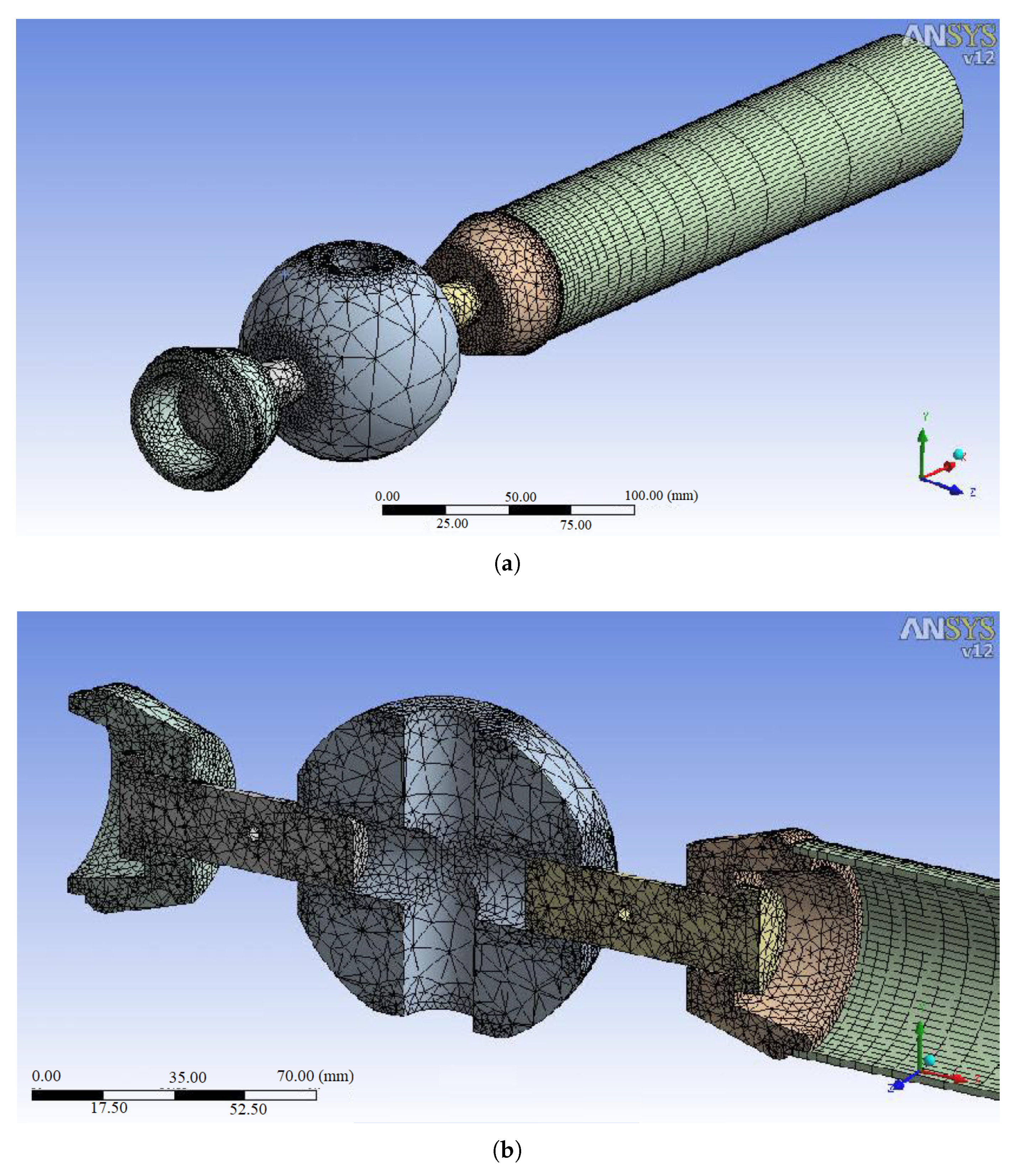
2. Geometry and Dimensions of MERO Double-Layer Joint

In double-layer joints, four screw holes are located on a base plane, which is similar to the MERO single-layer joints. In addition, four holes located in planes inclined to the center of the ball with an angle of 45° to the base plane allow for four new links to be connected to the MERO double-layer ball joint. In the present study, the outer diameter of the MERO ball joints considered in analyses are 98, 110, and 132 mm for which the distances between the caps (H) in the first layer of the ball joints were regarded as 85, 98, and 118 mm, respectively. Figure 2a,b and Figure 3a,b illustrate the dimensions and geometry of the MERO ball joint.

2.1. Grid Generation and Materials

Modeling, analysis and grid generation of the ball joint were conducted in ANSYS Workbench v.14.0. Solid-type element SOLD 45 was used for modeling the ball and grids were created carefully at the screw joint surfaces. Materials were modeled as isotropic with constant modulus of elasticity as E = 200 GPa. Further, the inflation option was activated in the holes and at least five grid layers were created near the holes in order to increase the accuracy of calculations, along with reducing the grid size. Grid generation has been shown in Figure 4a,b. Grid of the whole system modeled in ANSYS has been shown in Figure 5a,b.

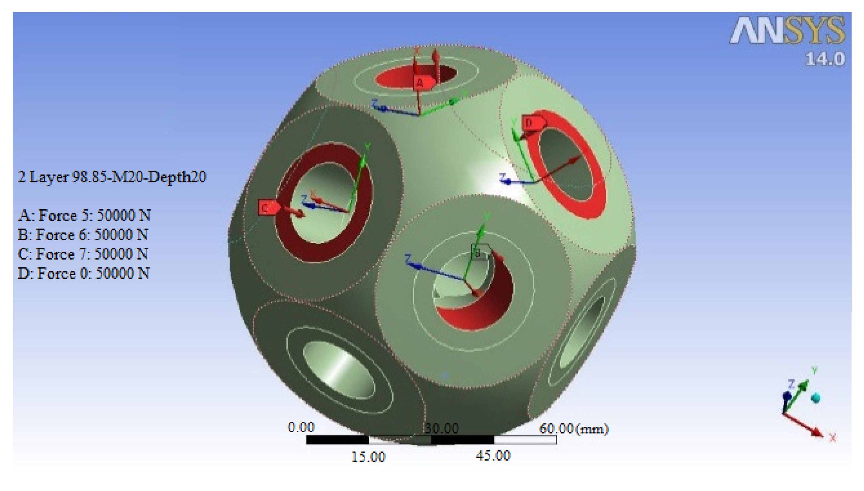
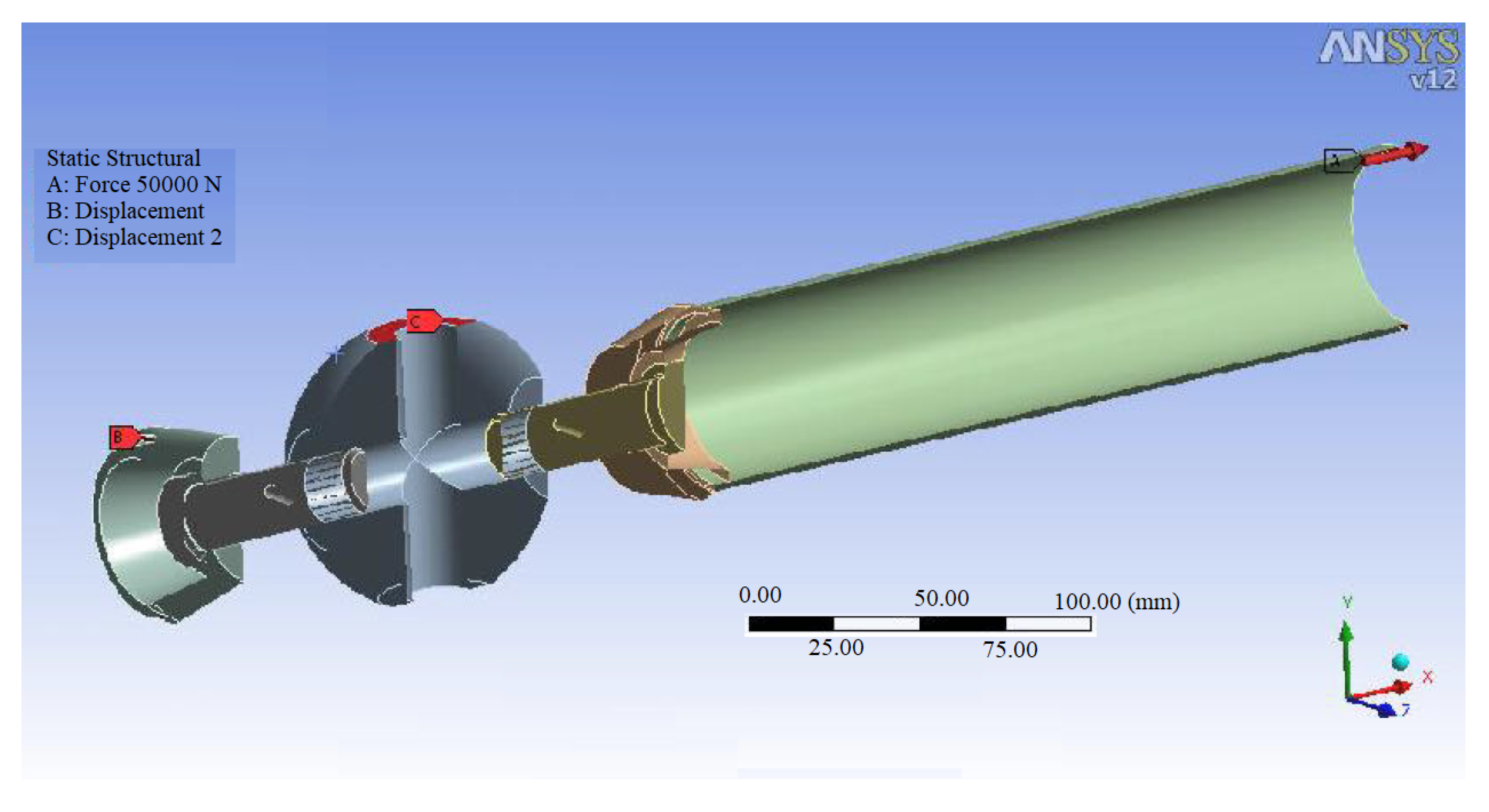
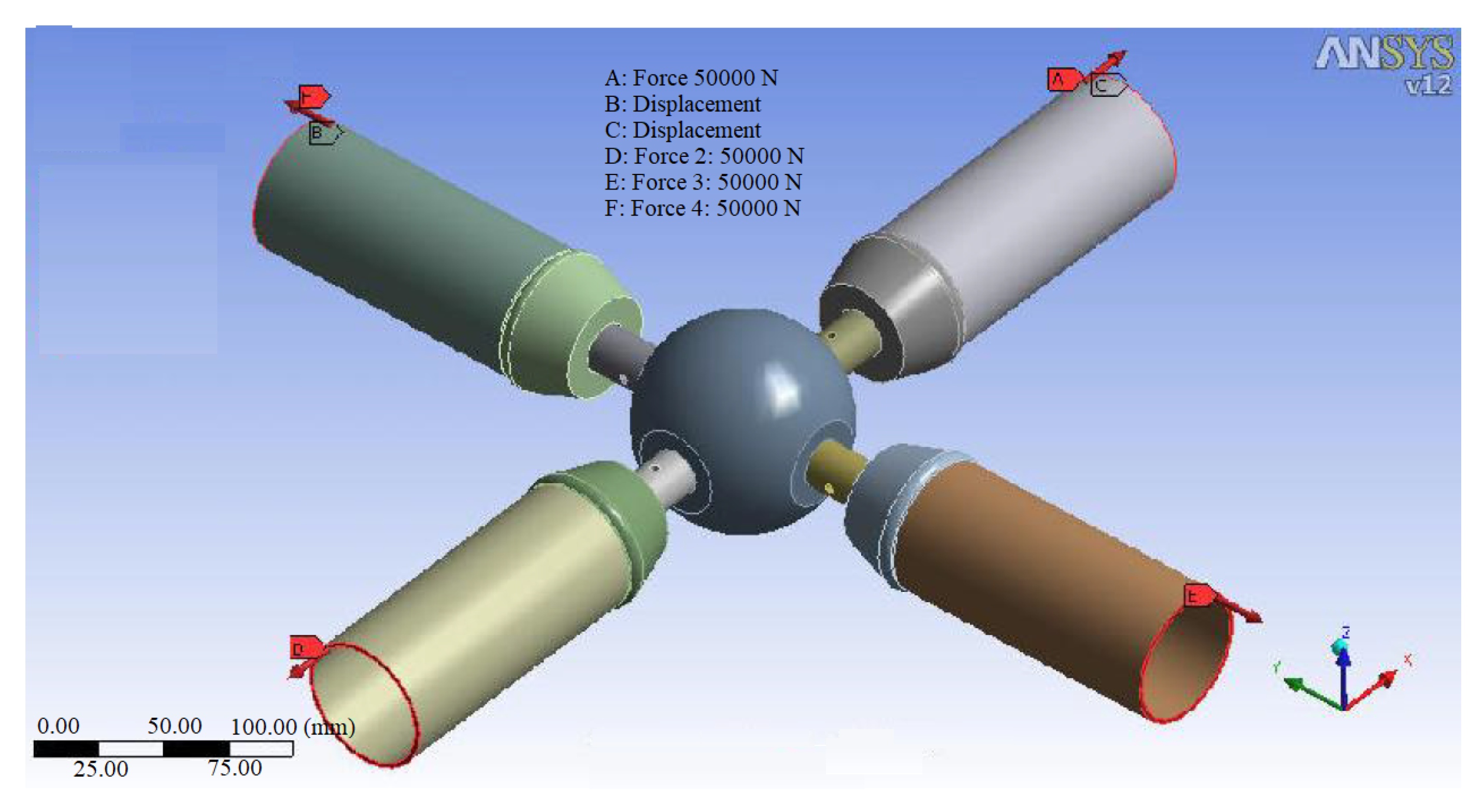
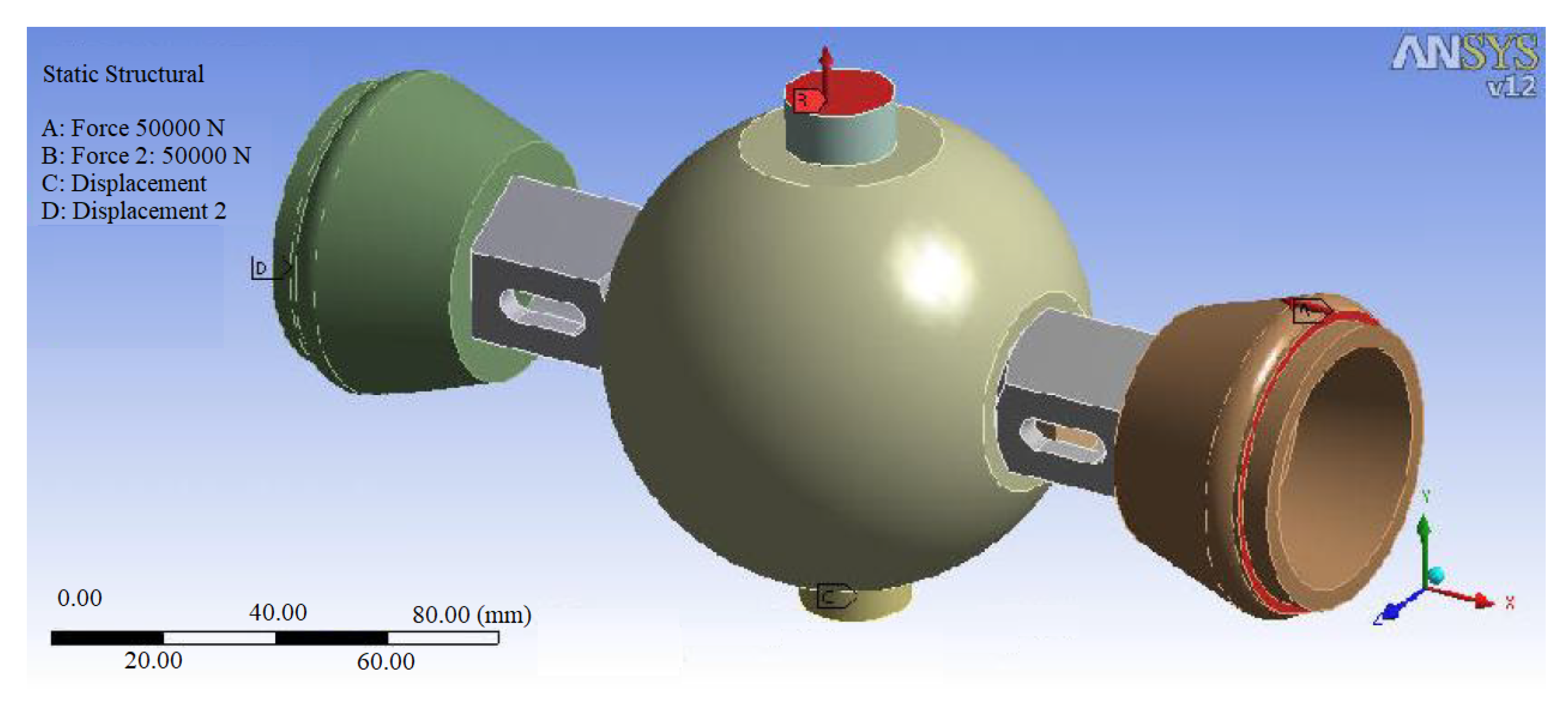
2.2. Loading and Analysis

In a MERO joint, the screws which are located in the base plane are always in tension, but inclined holes are loaded with a compression-tension pair force. The place, where forces are applied, is regarded as the most important subject in loading analysis. So, herein, to follow a practical loading condition, compressive loading has been applied to the conical piece while screws bear the tensile forces. Thus, in the tensile direction the effect of nuts and in the compressive loading direction the effect of details of screws can be neglected with a good approximation. Analyses in ANSYS were conducted through linear static analysis method and stress results presented in section 5 are Von Mises stresses generated in ball joints. Tensile forces are applied to threads of holes in the ball, whereas the location of the compressive loads is on the interface between the sleeve and the shear surface of the ball. The compressive-tensile force pair leads to a static equilibrium in the ball. Force values of 5 tons are applied to each point in the second layer of the joint. Figure 6 shows loading of the MERO joint in ANSYS. Loading of the system under a uni-axial 5 tons tensile force (red arrow) has been depicted in Figure 7, while Figure 8 and Figure 9 show the system subject to application of bi-axial and simultaneous compressive-tensile loading, respectively. No-displacement constraint in point B over the conical piece, and constraint in point C along z axis to avoid undesirable rotations are the applied boundary conditions. In modeling and simulations threads have not been modeled. Instead of modeling the threads over two surfaces of the screw and the hole, two cylindrical surfaces with permanent and complete connection (Bonded contact) are simulated which is an acceptable approximation in assembly collection simulations. Moreover, modeling details of threads, due to the specific geometrical nature of them, will result in point stress concentration and divergence of results to inexact values. To avoid this problem, grid of the threads region (crest and root) should be very fine. On the other hand, modeling such very find grids for threads will cause computational cost to increase significantly. Von Mises stress contours on the body of the screw under 5 tons tensile force have been illustrated in Figure 10a,b while the resultant stresses in the ball joint have been presented in Figure 11a,b. As can be observed in these figures, stress in two positions in the bolt has become critical which are beneath the screw head and the hole embedded in the screw.

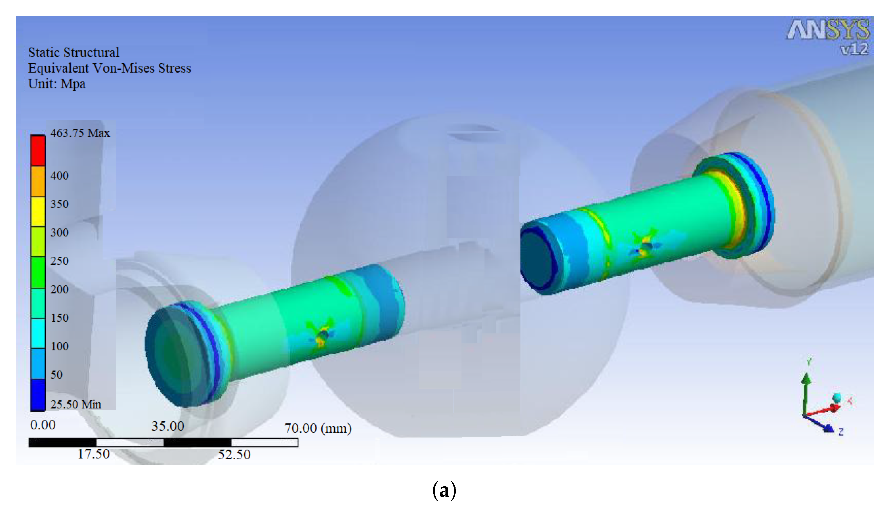
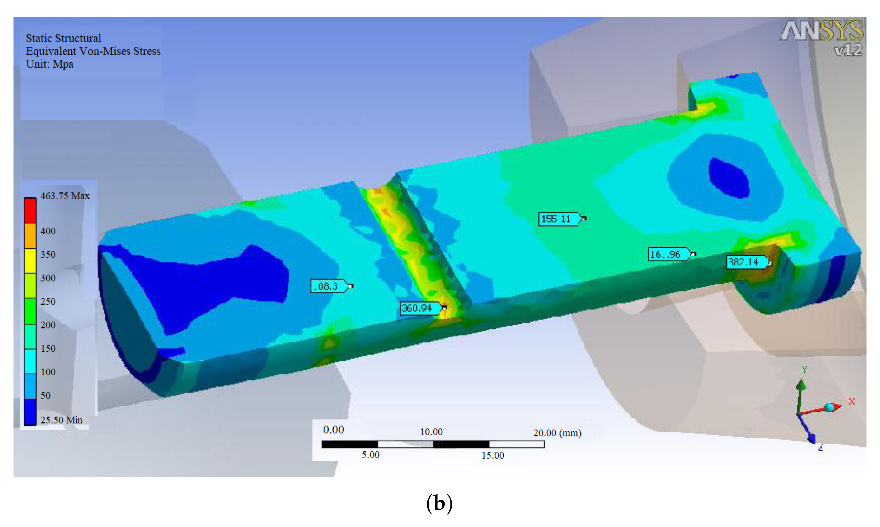
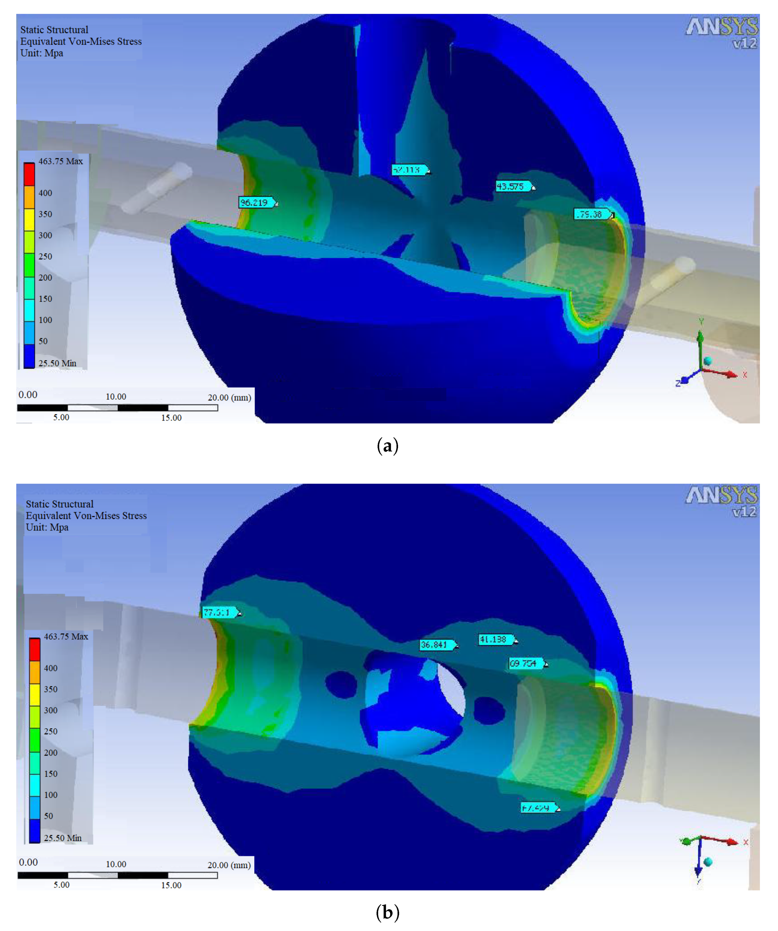
3. Results and Discussion

The present study evaluated three MERO joints with diameters of 98, 110, and 132 mm under the same tensile-compressive loading condition. In all numerical analyses, the first layer of the ball joint was loaded in one tensile force and the second layer in tow simultaneous compressive and tensile forces. All the simulations were performed in ANSYS v.14.0 software and the results were presented in three parts. In the first part, the effect of changing the screw size on the maximum stress level created in the double layer ball joint, under 8 axial tensile-compressive loads of 5 tons, was evaluated. Then, the maximum stress levels were calculated in three sizes of the ball joints for the applied loading conditions and for each screw size, in the second part. The last part was dedicated to the factor of safety (FOS) for different sizes of MERO joint, which was examined for different screw sizes under the same loading conditions. Finally, the optimal screw sizes were proposed for each MERO joint from multiple perspectives.

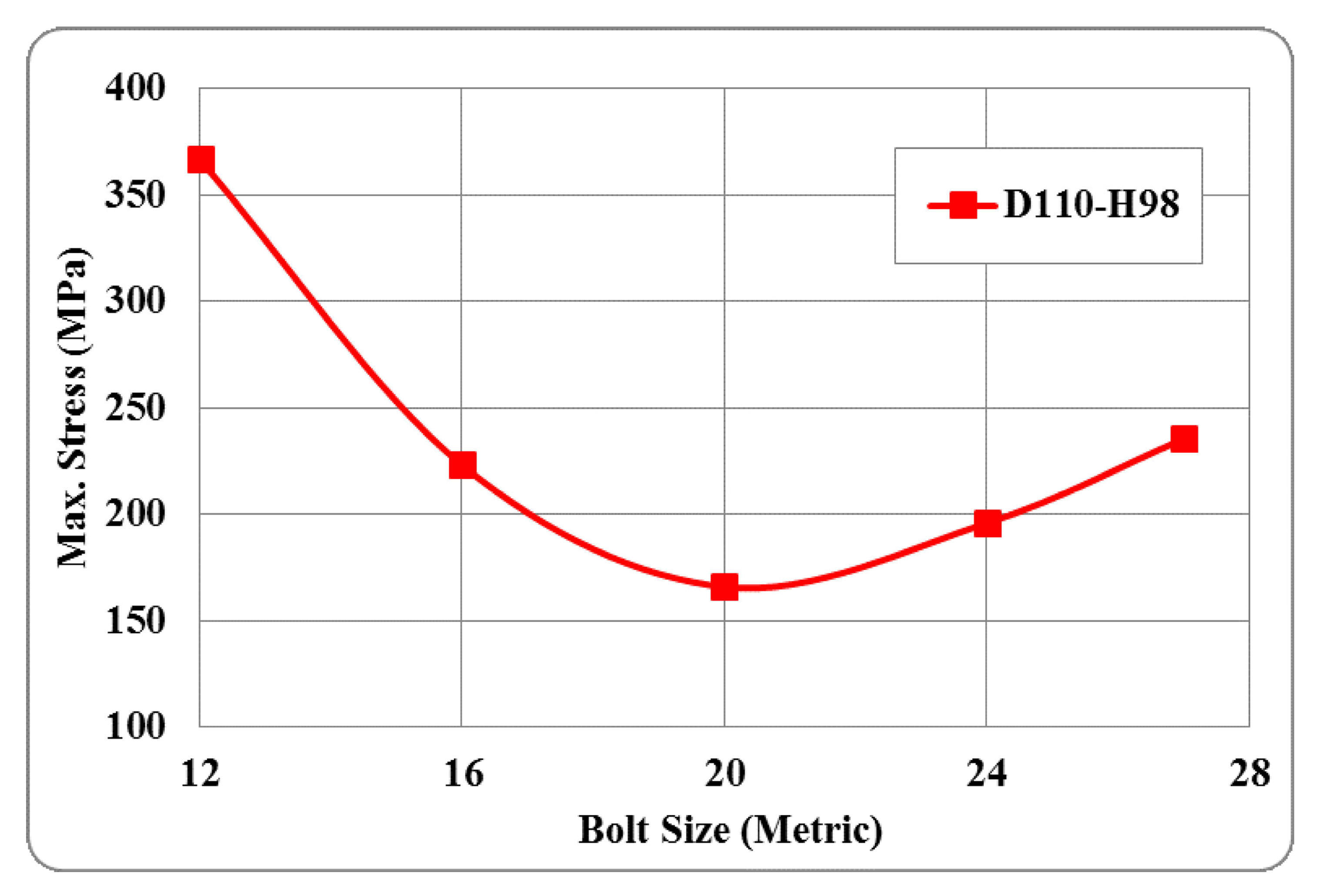
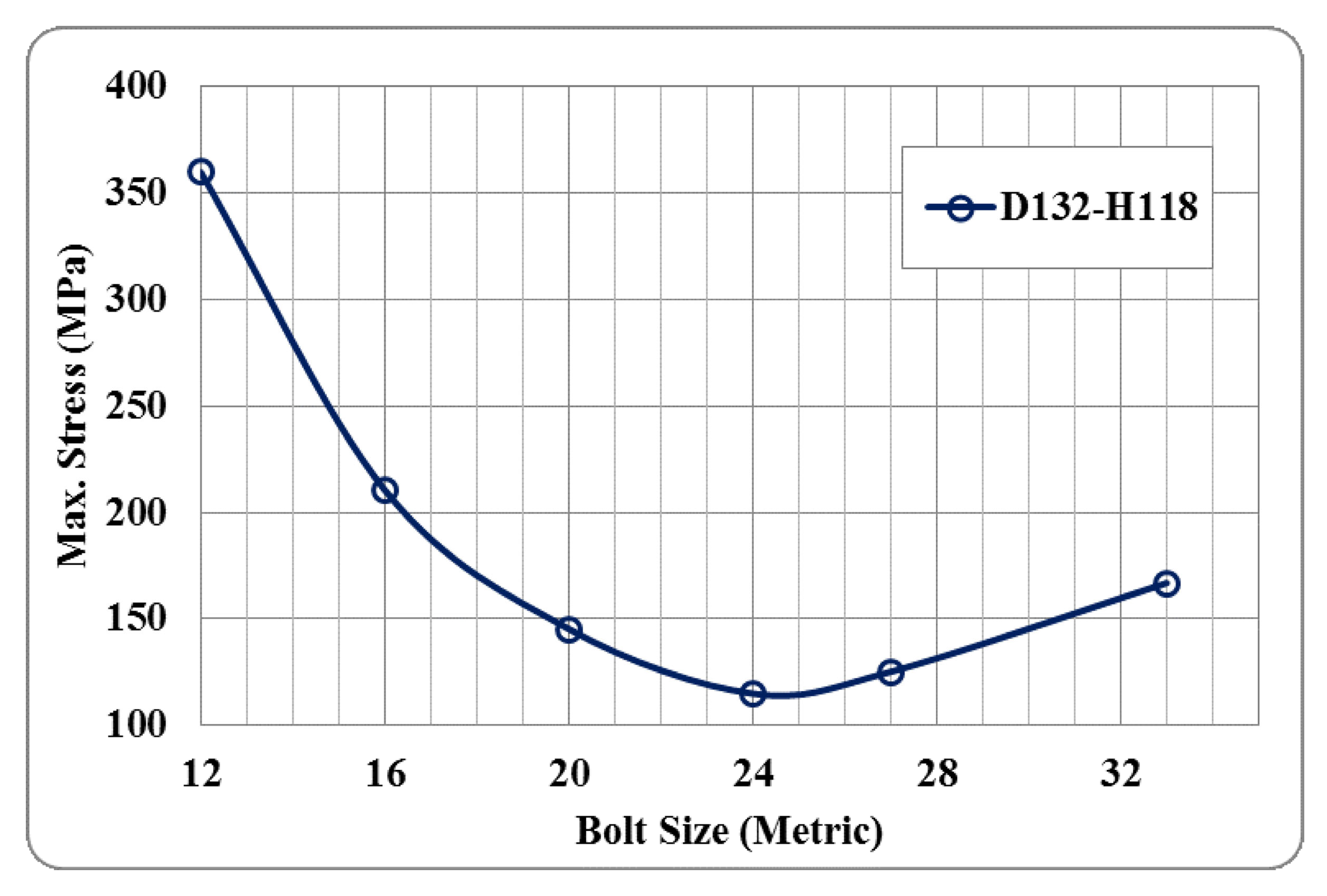
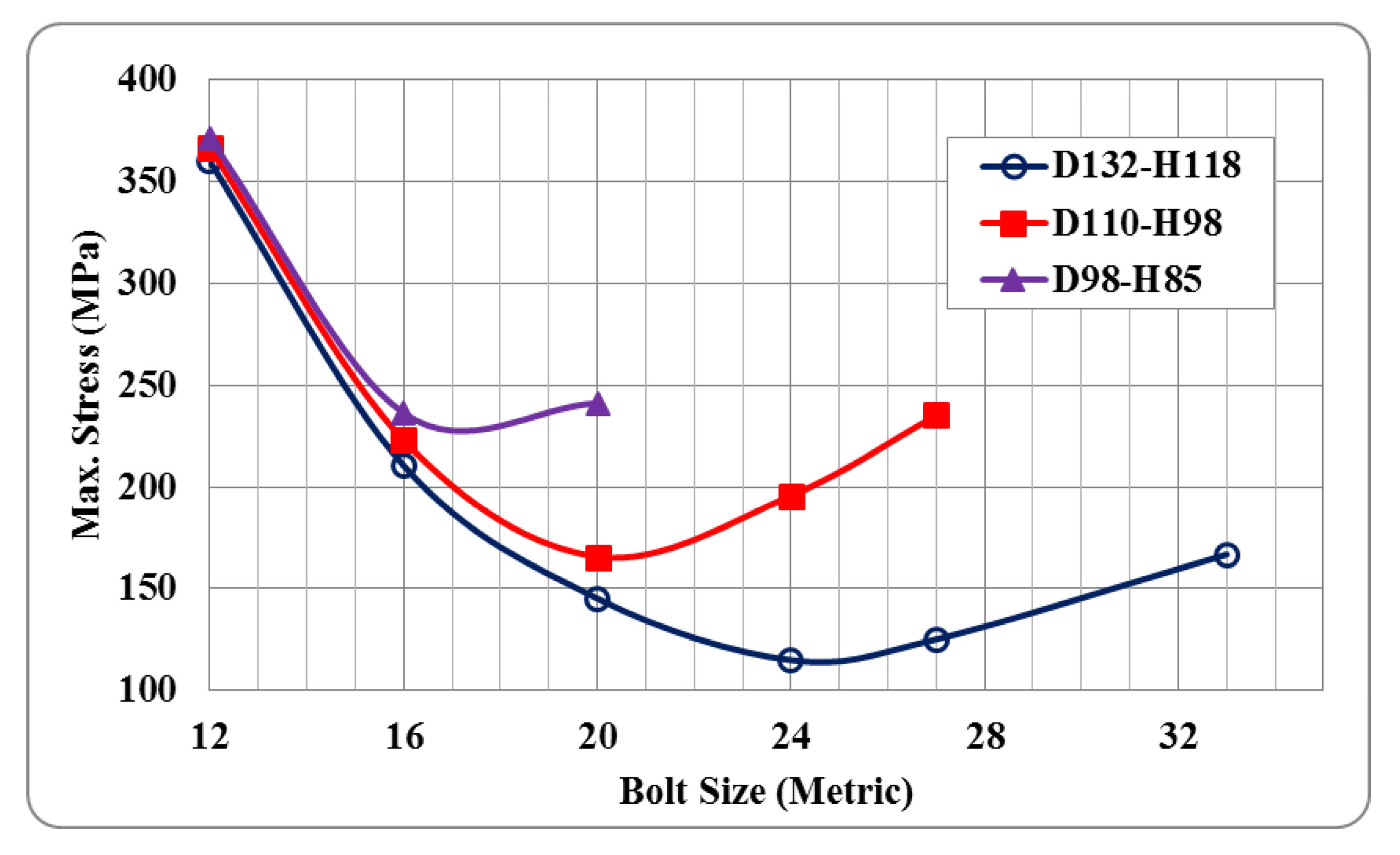
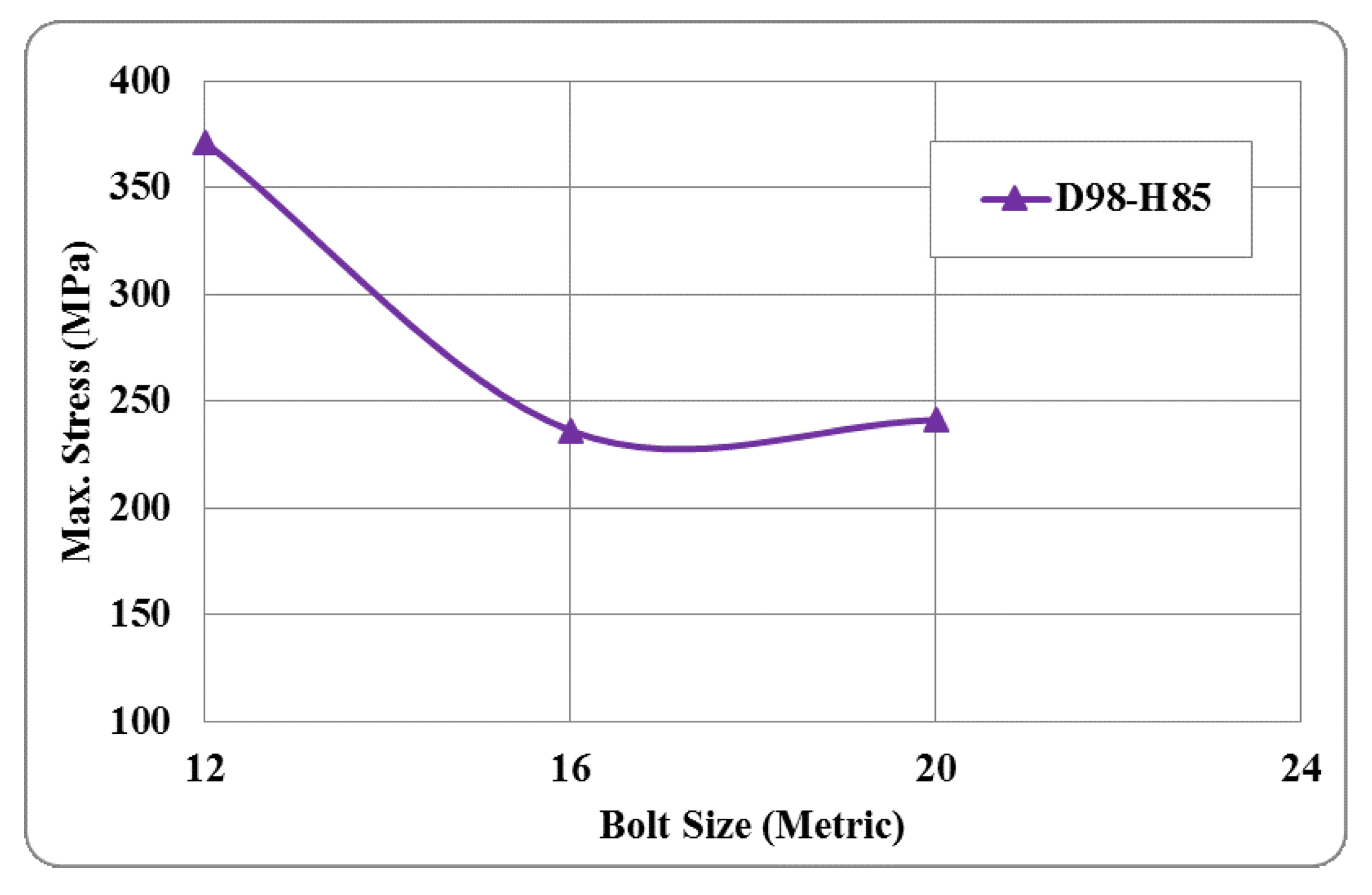
3.1. Effect of Changing the Screw Size on The Maximum Stress Level in the MERO Joint

The maximum stress levels in all three ball joints under application of four simultaneous tensile loads of 5 tons in the first layer of the ball joint and also four tensile or compressive loads of 5 tons in the second layer were calculated. Based on the geometry and dimensions of the MERO joint of diameter 98 mm, a maximum of three screw sizes of M12, M16, and M20 can be used for this joint as application of larger screws will result in their interference with each other in the joint. As shown in Figure 12, decreasing the screw size from M16 to M12 leads to a significant increase in the stress level. However, the maximum stress created in the ball joint for M16 and M20 was not substantially different. The reason is, even though increase in the screw size improves the stress distribution and decreases the stress values, interference of the stress fields overshadows these effects, hence leading to approximately a similar outcome.
Regarding the geometry of the MERO joint with the diameter of 110 mm, five screw sizes of M12, M16, M20, M24, and M27 can be used. The stress variations caused by different screw sizes in the ball joint had a parabolic behavior, the minimum value of which was obtained using the M20 screw, as illustrated in Figure 13. Decreasing or increasing the screw size significantly increased the stress level under the same load. This phenomenon can be explained as stress level in the MERO joint increases by the effects of stress concentration in smaller screw sizes, and the superposition of stress fields in larger sizes. As obvious in Figure 13, the effects of stress concentration were more significant than that of superposition of stress fields.
Moreover, regarding the geometry of MERO joint with diameter of 132 mm, six sizes of M12, M16, M20, M24, M28, and M33 for screws can be applied. Similar to the ball joint of 110 mm diameter, the stress variations due to various screw sizes indicated a parabolic behavior in the ball joint, and the minimum value which was achieved for the M24 screw, as seen in Figure 14.
Figure 15 superimposes and compares the results of the above-mentioned analyses, which indicates that a smaller ball joint will experience higher stress levels. Therefore, stronger materials should be utilized when using smaller ball joints. In addition, the parabolic behavior of the stress diagram proves that an optimal screw size can be recommended for each size of the MERO double-layer ball joint, for which the minimum stress level will be generated in the joint.

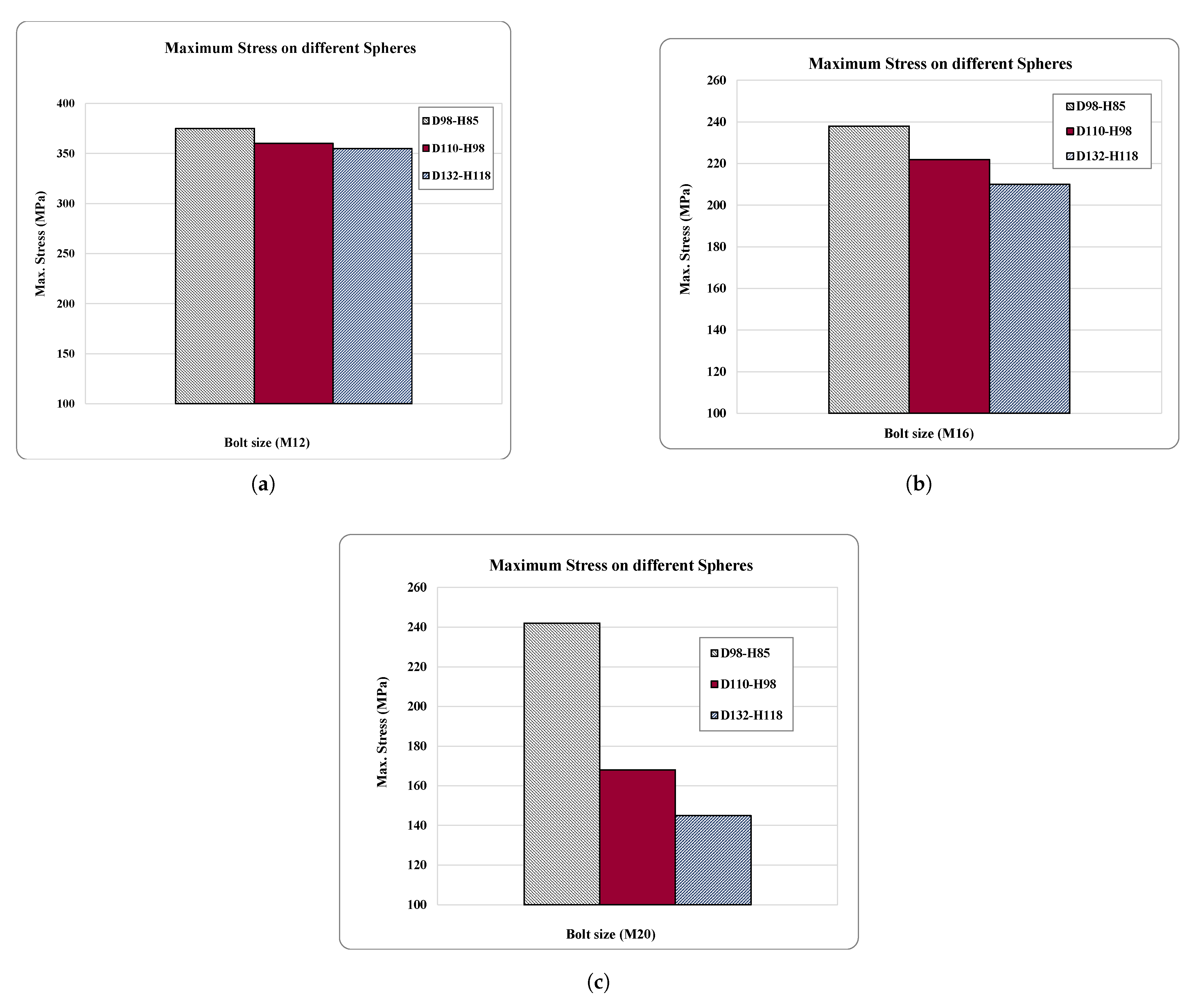
3.2. Comparing the Effect of the Ball Joint Size on the Stress Levels for Constant Screw Sizes

Effect of the ball joint sizes with diameters of 98, 110, and 132 mm for each screw size on the maximum stress level can be compared for the considered three screw sizes of M12, M16, and M20.
As depicted in Figure 16a, the maximum stress level in the ball joints for the small screw size of M12 is nearly independent of the ball joint sizes, and almost all of them should have the minimum yield strength of greater than 370 MPa, irrespective of the factor of safety. A similar conclusion can be drawn about the results acquired for M16 screw in Figure 16b which shows nearly minimal changes in stress levels.
Examining the results in Figure 16 and considering the stress levels generated in the ball joints of considered sizes for the screw size of M20 in Figure 16c, demonstrates that the influence of superposition of stress fields caused by the joint has been eliminated and the stress level has reduced by around 30% after increasing the ball diameter from 98 to 110 mm. However, increasing the diameter of the ball joint to over 110 mm, i.e., to 132 mm, does not significantly decrease the stress level, but mainly increases the weight of the ball joint and accordingly, the weight of the space frame structure, and the related costs. Thus, it is not recommended to use the M20 screw size for ball joints of diameter less than 100 mm, in terms of the stress level created in the ball joint, or for ball joints of diameter more than 110 mm in terms of the weight and the final cost of the space frame structure.

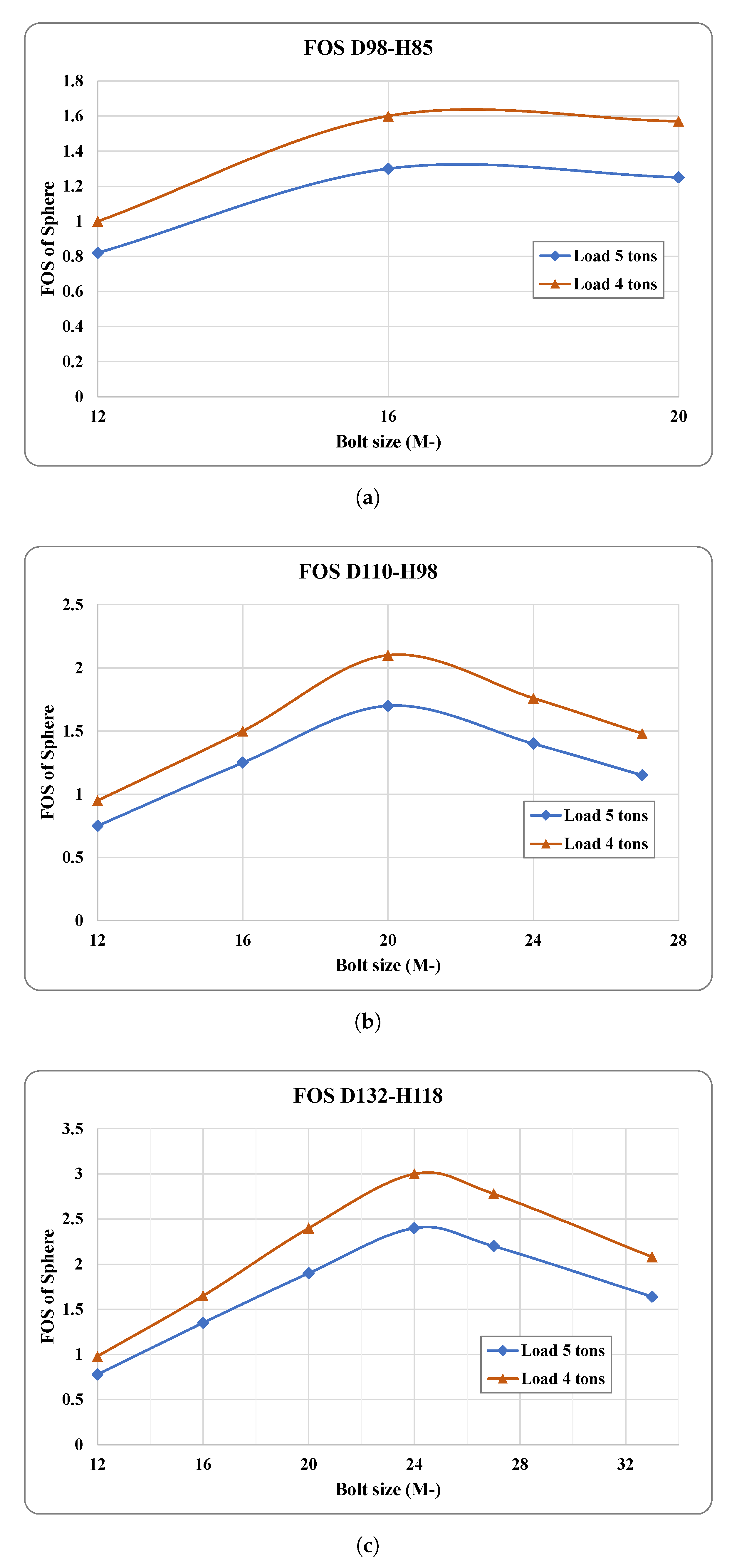
3.3. Comparing the Factor of Safety (FOS)

The above-mentioned ball joints underwent the axial loads of 4 and 5 tons, while considering the CK45 (1.1191) steel in accordance with standard DIN EN 10083-2:2006 [32] for the MERO ball joint, as well as the effects of the ball joints of three sizes on the level of stress, which had a decreasing trend with increase in diameter. Table 1 represents the effect of ball joint size on the yield stress level.
Numerical values related to the factor of safety (FOS) can be calculated through the amount of the yield stress presented in Table 1 and the results of the previous simulations. As shown in Figure 17, amounts of FOS under two loading conditions of 4 and 5 tons are compared in three separate diagrams.
As represented in Figure 17a–c the amount of the FOS is enhanced by increasing the diameter of the ball joint under the considered loading conditions and screw sizes. The highest FOS belongs to the ball joint of 132 mm for screw M24 under the axial load of 4 tons. In addition, these figures show that FOS has roughly a linear and reverse relationship with the amount of the applied load. It is noteworthy that M12 screw size is not recommended for the loads more than 4 tons, since as apparent from above figures the corresponding FOS would be very low and almost below 1 in all the cases.

4. Conclusions

In this research paper, a brief introduction and literature review on the space frame structures using MERO ball joints, their importance, applications, materials, geometries, dimensions, and their potentials and capabilities were presented. The key role of joints in space frame structures, their modeling and dynamic behavior, flexibility of the joint in simulations and their effect on the stability and integrity of the whole structure was discussed briefly by referring to the research conducted in literature. Keeping the significance of joints in mind and focusing on the screw size and its corresponding effect on the maximum stress levels created in the ball joints, factor of safety (FOS) and the final weight and cost of the space frame, analyses were conducted in ANSYS finite element (FE) software by considering screw sizes of M12 to M33, and ball joints of diameters 98, 110, and 132 mm under tensile and compressive loads of 4 and 5 tons.
Analysis results demonstrated that under the considered loading conditions, smaller ball joints will experience higher stress levels, and, thus, stronger materials should be applied for them. Furthermore, the parabolic behavior of the stress diagram proved that an optimal screw size can be recommended for each size of the MERO double-layer ball joint, for which the minimum stress level will be generated in the joint. Maximum stress level created in the ball joint for three sizes of 98, 110, and 132 mm for each of screws M12, M16, and M20 was evaluated. For screw M20 there is a sharp reduction in stress level in the ball joint from 98 to 110 mm while increasing the ball diameter more than 110 mm for this screw or the ball diameter from 98 to 132 mm for other screws does not have a significant reduction trend. So, application of screw M20 for ball joints of diameter less than 100 mm or more than 110 mm is not recommended to keep a trade-off between the optimal stress level and the final cost of the structure. Regarding the FOS, it was observed that its value is improved by the increase in the ball diameter and has a roughly linear and reverse relationship with the amount of the applied load. Results showed that screw M12 is not appropriate for loads more than 4 tons as it will result to an FOS of less than 1.
Finally, based on the obtained simulation results of the present study, it is recommended to apply the screw M16 for the ball joint of diameter 98 mm, M20 for the ball joint of diameter 110 mm, and M24 screw for the ball joint with diameter of 132 mm to simultaneously obtain the optimal values of stress level generated in the ball joint, FOS, and cost of the structure. Therefore, results of this study show that for analysis and design of space frame systems using MERO joint, a wise selection of the screw size for each appropriate MERO ball joint size for the considered structural configuration of the system in every architectural form can be adopted to obtain the best possible results in terms of the structural responses of the system and construction cost.
Moreover, according to the observed stress concentrations under applied loads under the screw head and in the location of the embedded hole in the screw below general recommendations can be drawn:
  • As far as it is possible, it is recommended to avoid embedding a hole in the body of the screw or another mechanism is utilized for rotation and bolt tightening, like press-fitting of the pin in the hole, to prohibit stress concentration in the screw.
  • A fillet is created under the screw head to decrease the stress concentration in this location.
  • In case of a fillet generation under the screw head as mentioned above, in the corresponding location over the internal surface of conical piece hole, an appropriate bevel is created to assure a complete contact between the lower surface of the screw head and the internal surface of the conical piece hole and stress concentration is decreased, simultaneously.

Author Contributions

Conceptualization, Y.D. and A.M.; methodology, A.M.; validation, Y.D. and A.M.; formal analysis, A.M.; investigation, A.M. and S.E.A.H.; resources, A.M. and Y.D.; data curation, S.E.A.H. and E.H.; writing—original draft preparation, S.E.A.H. and E.H.; writing—review and editing, S.E.A.H. and E.H.; visualization, S.E.A.H.; supervision, Y.D.; project administration, A.M. and Y.D.; All authors have read and agreed to the published version of the manuscript.

Funding

This research received no external funding.

Institutional Review Board Statement

Not applicable.

Informed Consent Statement

Not applicable.

Data Availability Statement

No data was reported.

Acknowledgments

Not applicable.

Conflicts of Interest

The authors declare no conflict of interest.

References

  1. Golabchi, M.; Golabchi, M. Fundamentals of Designing Space Frame Structures (Persian Language), 1st ed.; Pars University Press: Tehran, Iran, 2016. (In Persian) [Google Scholar]
  2. Ali, M.I.; Fan, F.; Khakina, P.N.; Ma, H. Cost-effective design of space structures joints: A review. Int. J. Struct. Constr. Eng. 2013, 7, 21–25. [Google Scholar]
  3. Subramanian, N. Principles of Space Frame Structures; Wheeler Publishing: Allahabad, India, 1983. [Google Scholar]
  4. Abdolvand, R. Dynamic Analysis and Modeling of Space Frame Structures with a Semi-Rigid System of MERO Ball Joint. 2001. Available online: https://www.tpbin.com/thesis-details/167 (accessed on 18 October 2021). (In Persian).
  5. Chilton, J. Space Grid Structures; Routledge: London, UK, 1999. [Google Scholar]
  6. Code of Practice for Skeletal Steel Space Structures Office of Deputy for Strategic Supervision Bureau of Technical Execution Systemstructure Code No. 400.2010. Available online: http://tec.mporg.ir (accessed on 18 October 2021).
  7. Arekar, V.A.; Bhavsar, B. Analytical study of MERO connector in double layer grid structure. IJLTET 2013, 2, 35–42. [Google Scholar]
  8. Ma, H.; Fan, F.; Cao, Z.; Cui, M.; Shen, S. Numerical simulation of semi-rigid joints in single-layer dome structures. J. Int. Assoc. Shell Spat. Struct. 2011, 52, 3–18. [Google Scholar]
  9. Subramanian, N. Space Structures: Principles and Practice; Multi-Science Publishing Co.: Essex, UK, 2007; Volume 2, p. 820. ISBN 0906522420. [Google Scholar]
  10. Jaspart, J.P. General report: Session on connections. J. Constr. Steel Res. 2000, 55, 69–89. [Google Scholar] [CrossRef]
  11. Nethercot, D. Frame structures: Global performance, static and stability behaviour: General report. J. Constr. Steel Res. 2000, 55, 109–124. [Google Scholar] [CrossRef]
  12. Dai, L. Finite-element model updating of the traditional beam–column joint in Tibetan heritage buildings using uniform design. Adv. Struct. Eng. 2020, 23, 1890–1901. [Google Scholar] [CrossRef]
  13. Abd-Elhady, A.; Abu-Sinna, A.; Atta, M.; Sallam, H.E.D.M. Identification of damage stages in bolted metallic joints for different joint geometries and tightening torques using statistical analysis. Adv. Struct. Eng. 2020, 23, 911–923. [Google Scholar] [CrossRef]
  14. Wong, C.; Mak, W.; Ko, J. System and parametric identification of flexible connections in steel framed structures. Eng. Struct. 1995, 17, 581–595. [Google Scholar] [CrossRef]
  15. Hadianfard, M.; Razani, R. Effects of semi-rigid behavior of connections in the reliability of steel frames. Struct. Saf. 2003, 25, 123–138. [Google Scholar] [CrossRef]
  16. Ihaddoudène, A.; Saidani, M.; Chemrouk, M. Mechanical model for the analysis of steel frames with semi rigid joints. J. Constr. Steel Res. 2009, 65, 631–640. [Google Scholar] [CrossRef]
  17. Ma, H.; Shan, Z.; Fan, F. Dynamic behaviour and seismic design method of a single-layer reticulated shell with semi-rigid joints. Thin-Walled Struct. 2017, 119, 544–557. [Google Scholar] [CrossRef]
  18. Ma, H.; Ma, Y.; Yu, Z.; Fan, F. Experimental and numerical research on gear-bolt joint for free-form grid spatial structures. Eng. Struct. 2017, 148, 522–540. [Google Scholar] [CrossRef]
  19. Feng, R.q.; Wang, X.; Chen, Y.; Cai, Q. Static performance of double-ring joints for freeform single-layer grid shells subjected to a bending moment and shear force. Thin-Walled Struct. 2018, 131, 135–150. [Google Scholar] [CrossRef]
  20. Li, H.; Taniguchi, Y. Load-carrying capacity of semi-rigid double-layer grid structures with initial crookedness of member. Eng. Struct. 2019, 184, 421–433. [Google Scholar] [CrossRef]
  21. Tsavdaridis, K.D.; Feng, R.; Liu, F. Shape optimization of assembled single-layer grid structure with semi-rigid joints. Procedia Manuf. 2020, 44, 12–19. [Google Scholar] [CrossRef]
  22. Liu, F.; Feng, R.; Tsavdaridis, K.D. Form finding of assembled lattice structure considering the effect of joint stiffness. In Structures; Elsevier: Amsterdam, The Netherlands, 2021; Volume 31, pp. 1096–1105. [Google Scholar]
  23. Kato, S.; Mutoh, I.; Shomura, M. Collapse of semi-rigidly jointed reticulated domes with initial geometric imperfections. J. Constr. Steel Res. 1998, 48, 145–168. [Google Scholar] [CrossRef]
  24. López, A.; Puente, I.; Serna, M.A. Direct evaluation of the buckling loads of semi-rigidly jointed single-layer latticed domes under symmetric loading. Eng. Struct. 2007, 29, 101–109. [Google Scholar] [CrossRef]
  25. López, A.; Puente, I.; Serna, M.A. Numerical model and experimental tests on single-layer latticed domes with semi-rigid joints. Comput. Struct. 2007, 85, 360–374. [Google Scholar] [CrossRef]
  26. Ma, H.; Fan, F.; Shen, S. Numerical parametric investigation of single-layer latticed domes with semi-rigid joints. J. Int. Assoc. Shell Spat. Struct. 2008, 49, 99–110. [Google Scholar]
  27. Fan, F.; Ma, H.h.; Cao, Z.G.; Shen, S.Z. Direct estimation of critical load for single-layer reticulated domes with semi-rigid joints. Int. J. Space Struct. 2010, 25, 15–24. [Google Scholar] [CrossRef]
  28. Hou, R.; Beck, J.L.; Zhou, X.; Xia, Y. Structural damage detection of space frame structures with semi-rigid connections. Eng. Struct. 2021, 235, 112029. [Google Scholar] [CrossRef]
  29. Amiri, J.V.; Davoodi, M. Modeling the semi-rigid behaviour of the MERO jointing system. Space Struct. 5 2002, 1, 309–316. [Google Scholar] [CrossRef]
  30. Davoodi, M.; Ebadi Jamkhaneh, M. Presenting a numerical model and investigating of MERO joint system components under combined axial and bending moment loading. In Proceedings of the 4th National Spatial Structures Conference, Tehran University, Tehran, Iran, 25–26 May 2014. (In Persian). [Google Scholar]
  31. Ebadi Jamkhaneh, M.; Davoodi, M.R.; Ebadi Jamkhaneh, J.A. Assessment of the ball joint behavior under combine loading. Modares Civ. Eng. J. 2017, 17. [Google Scholar]
  32. DIN EN 10083-2. Steels for Quenching and Tempering—Part 2: Technical Delivery Conditions for Non Alloy Steels, English Version of DIN EN 10083-2:2006-10; European Committee for Standardization: Brussels, Belgium, 2006.
Figure 1. Main components of the space frame structure.
Asi 04 00084 g001
Figure 2. The main dimensions of MERO Joint (H: The distance between two caps on the first layer of the joint). (a) View 1, (b) View 2.
Asi 04 00084 g002
Figure 3. The geometry of the MERO double-layer ball joint. (a) View 1, (b) View 2.
Asi 04 00084 g003
Figure 4. The grid of MERO joint. (a) Section, (b) Perspective2.
Asi 04 00084 g004
Figure 5. The grid of the whole system including the MERO joint, pipe, conical piece, sleeve, and the screw. (a) Perspective, (b) Section.
Asi 04 00084 g005
Figure 6. Applying a load to the MERO joint.
Asi 04 00084 g006
Figure 7. Loading of the system under a uni-axial 5 tons tensile force.
Asi 04 00084 g007
Figure 8. Loading of the system under bi-axial 5 tons tensile forces.
Asi 04 00084 g008
Figure 9. Loading of the system under simultaneous compressive-tensile 5 tons forces.
Asi 04 00084 g009
Figure 10. Von Mises stress contour over the body of the screw under a 5 tons tensile force. (a) Perspective, (b) Section.
Asi 04 00084 g010aAsi 04 00084 g010b
Figure 11. Von Mises stress contour in MERO joint ball under a 5 tons tensile force. (a) Perspective, (b) Section.
Asi 04 00084 g011
Figure 12. Effect of the screw size on the maximum stress on the ball joint with the diameter of 98 mm.
Asi 04 00084 g012
Figure 13. Effect of the screw size on the maximum stress on the ball joint with the diameter of 110 mm.
Asi 04 00084 g013
Figure 14. Effect of the screw size on the maximum stress on the ball joint with the diameter of 132 mm.
Asi 04 00084 g014
Figure 15. A comparison regarding the effect of the screw size on the maximum stress in the three MERO double-layer ball joints.
Asi 04 00084 g015
Figure 16. A comparison among the effects of the ball joint size variations on the load and constant screw size for three sizes of (a) M12, (b) M16, and (c) M20.
Asi 04 00084 g016
Figure 17. Comparing the effect of changing screw size on the factor of safety of the ball joint on the axis loads of 4 tons and 5 tons for three sizes of (a) M12, (b) M16, and (c) M20.
Asi 04 00084 g017
Table 1. Effect of the ball joint size on the yield stress level.
D (mm)Yield Stress-Normalized (MPa)
16–100305
100–250275
Publisher’s Note: MDPI stays neutral with regard to jurisdictional claims in published maps and institutional affiliations.

