1. Introduction
Recently, there are many researchers from the academic and industry sectors that have turned their attention to developing the vertical axis wind turbine (VAWT), where the main advantage of the VAWTs is capturing the wind from any direction. This is considered a significant feature in urban areas, where it is difficult to know the major direction of wind due to the presence of a high number of obstacles (natural and unnatural) and flow-directing influences. In the urban areas, a new idea has been introduced to increase the production of clean energy, by installation of the small power vertical axis wind turbines on the roof of high constructions. There is another method that encouraged to build the offshore vertical axis wind turbines with huge sizes.
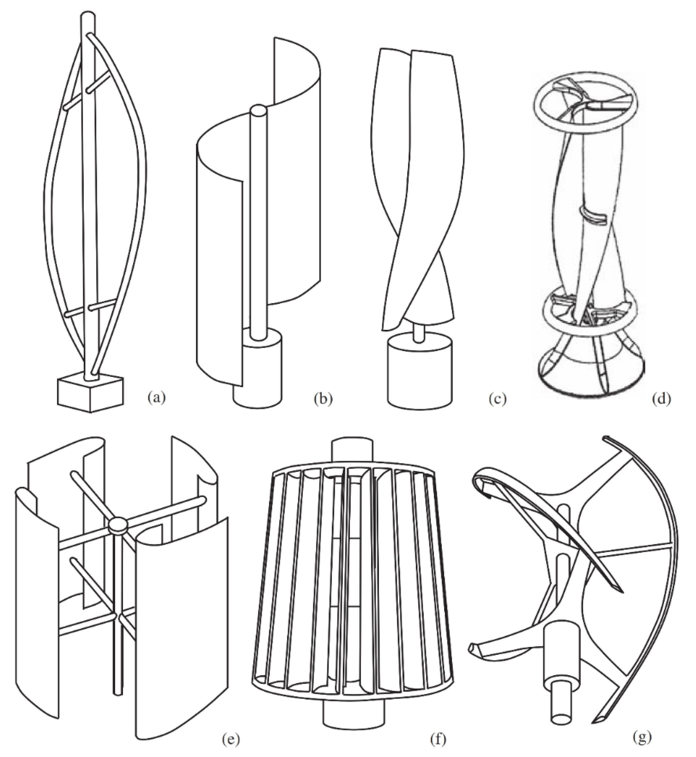
Figure 1 shows different typical vertical axis wind turbines.
On the other hand, many other problems appeared during the design and after installation of the vertical axis wind turbines such as unbalance, vibration and difficulty to expect the output power. Extensive experimental research was achieved on the axial wind turbine in the field in addition to developing specialist software that led to introducing a new model by Ion Paraschivoiu. This model was called the Double-Multiple Stream tube (DMS) model. Two parameters were adopted and used in the circular path that related to the blade and extraction of energy. These parameters were introduced by the following terms in the upstream and downstream rotor halves in relation to the rotational axes [
1]. The theoretical approach was applied using QBlade software to investigate and analyze different types of airfoils such as DU-06-W200, NACA 0018, and NACA 0021. The produced power assuming different configurations of the twist angle (ψ = 30°, 60°, 90°, and 120°) for 1 kW axial wind turbine was analyzed. The extracted energy by the wind blade when reducing the fluid velocity was also determined. Acceptable results were obtained based on the principle of Double-Multiple Stream tube model (DMS). Additionally, it has been found that reliable results can be obtained for different configurations of the axial wind turbine using blade design simulation tool, where the cost and time will be much higher when using the experimental work to obtain the same results [
2].
The main objective in the design of wind turbine is to obtain the optimal solution of the VAWT based on the new design approach to enhance the extracted power by minimizing the changes excluding the movable parts. The influences of the change in the aspect ratios as well as the aerodynamic shape using a classical Darrieus rotor with SANDIA shape was studied. NACA0018 and NACA0012 blade profiles were used to enhance the characteristics of the rotor. It was found that each shape of the aerodynamic and aspect ratio has a significant impact on the output power. These results encouraged more researchers to investigate in this area to enhance the performance and output power of the vertical axis wind turbine [
3]. Previous studies aimed to obtain the optimal design of the vertical axis wind turbine using QBlade software. It was found that the main advantage of using this software was analyzing the velocity of wind that comes from different directions with high accuracy, where the installation of generators and connecting the electrical cables for this kind of wind turbine is easier and of less cost compared with the horizontal wind turbine.
The wide range of results and the high accuracy led to making QBlade software to be a significant design tool to analyze different kinds of wind turbines [
4]. This software was used to study the effect of thickness of the airfoil blade on the behavior and performance of the vertical axis wind turbines. The results can be presented by using different kinds of plots; therefore, it can be found that the optimal design is based on the different aerodynamic governing features. Additionally, the dynamic influences on the blade section lift (propeller), coefficients of pitching moment and the drag force can be studied. It was concluded that the thicker profiles are more efficient than thinner profiles. It was shown that the VAWT of eggbeater types with thicker profiles is more suitable than thinner profiles because of the lift forces [
5]. There are other researchers [
6,
7,
8,
9,
10,
11,
12] who studied that rotating blade from a different point of view, where they investigated the stresses and vibration characteristics of a rotating blade that works under different kinds of conditions in general and especially the wind speed.
The finite element method was used to analyze the stresses and deformations for the straight blade of wind turbine (H-Darrieus) with a power rating of 2.5 kW [
13]. The 3D model of a wind turbine blade was developed using SolidWorks and computer-aided design (CAD) softwares. No structural failures were expected based on the obtained simulation of the two systems because the safety factors for both cases were high enough. It was investigated that the torsional aero-elasticity of the blade of the H-type VAWT are subjected to stall as well as post-stalling conditions under different Reynolds regimes [
14]. A model has been proposed based on the combination of the Double Multi-Stream tubes (DMST) model and the nonlinear multi-criteria Cl-α equations that are used to simulate the aerodynamics problem. The main findings demonstrated that the blade undergoes aero-elastic torsion between +7° and +12° at higher TSR values and between −4° and +19° at lower TSR values. As a result, running the blade at high TSR values is supposed to extend its lifetime. A fully automatic procedure for optimizing the VAWT cross-section airfoil has been developed and demonstrated [
15]. The goal was to increase the torque while placing traditional restrictions on the structure of wind turbines, such as tip speed ratio, power, and blade profile. The simplicity and functionality of the modular design and simulation system enabled it to be conveniently integrated with the parallel differential evolution algorithms that were used to produce an efficient blade configuration to maximize the performance of wind turbine. The effect of blade number on drag type VAWT performance was examined [
16]; 3-blade, 5-blade, and 6-blade were used to optimize the blade width for each VAWT at optimum power efficiency. Different numbers of blades were used for the turbine with the same radius and inlet wind speed. It was found that the reliability of the wind turbine and the maximum performance increased significantly.
Figure 1.
Several typical types of vertical-axis wind turbines: (
a) Darrius; (
b) Savonius; (
c) Solarwind; (
d) Helical; (
e) Noguchi; (
f) Maglev; (
g) Cochrane [
17].
Figure 1.
Several typical types of vertical-axis wind turbines: (
a) Darrius; (
b) Savonius; (
c) Solarwind; (
d) Helical; (
e) Noguchi; (
f) Maglev; (
g) Cochrane [
17].
Chen et al. [
18] presented a new model of electric load forecasting, where the fuzzy c-means clustering was used to find the clustering center. Additionally, the Least Square Support Vector Machine (LSSVM) approach was applied to simulate the optimized resultant series. The results were verified with the experimental results. It was found that the proposed GHSA-FTS-LSSVM model effectively generates more accurate predictive results.
3. Theoretical Background
The fundamental equations that were used to build the mathematical model of the VAWT will be presented with details in this section. The relative velocity of the blade can be written as follows:
where
V∞ is undisturbed air velocity,
Rw is the blade velocity at equator radius and
ω is speed of rotation for the blades.
The significant velocities when using the DMS calculation approach are:
V∞: The inflow velocity of the undisturbed freestream flow.
V: The upwind induced velocity that occurred owing to the extraction energy from blades at upstream rotor half.
Ve: Equilibrium velocity that appeared in the plane between up—and downstream rotor half, which denotes the velocity of upstream rotor disk (wake) and the inflow velocity of the downstream rotor disk.
V’: The downwind induced velocity that occurred owing to the extraction energy of blades in the downstream rotor half.
V”: The wake velocity of the complete double disk.
The first step of the calculations process is to determine these mentioned velocities, and then the parameters of extraction energy in the up-and downstream rotor half can be defined as follows:
The global tip speed ratio is the relative speed of rotation of the (VAWT):
Additionally, the simulation of the turbine enables the determination of the inflow wind profile. There are three potential options which are:
4. Power Generation Calculations
Power generated by the wind turbine is influenced at a particular time mostly by air mass elevated of the rotor blades. An increase in tip speed ratio leads to a decrease in the mass being lifted and will affect the power output. The maximum power that the turbine could capture depends on turbine design including blade airfoil, and pitch angle.
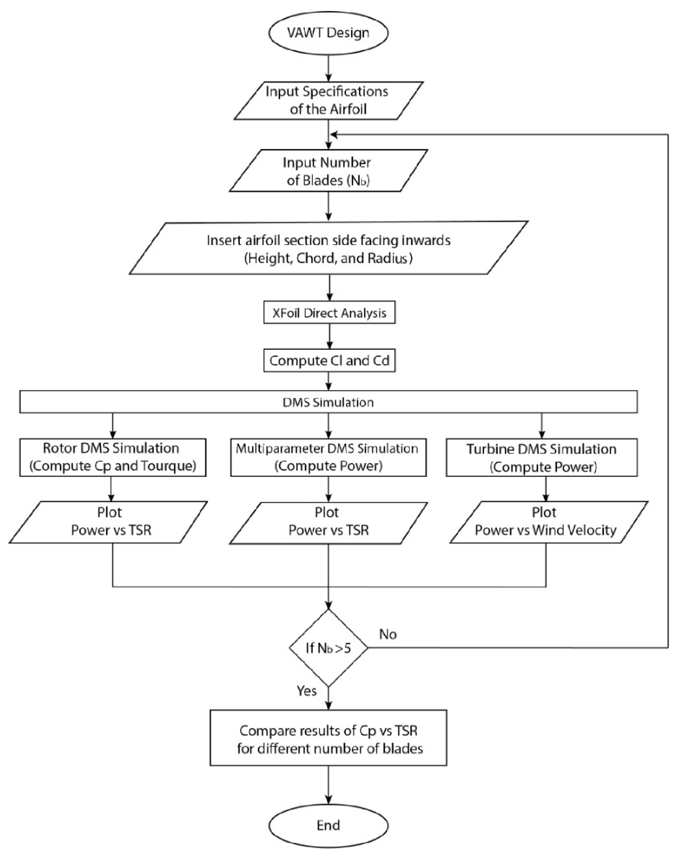
Figure 2 shows the details of the developed approach used in this research paper to analyze and optimize the vertical axial wind turbine.
The produced power by the wind turbine is determined based on the power coefficient (CP) including the tip speed ratio (λ) and pitch angle (β) parameters. The tip speed ratio λ will often adjust over time because it is determined by the turbine rotor’s angular velocity. The feedback from the turbine rotor to the ratio of tip speed can be created in a closed loop.
The available kinetic energy in the wind that can be converted to mechanical energy is not exceeding 59% of the total value (theoretically), as specified in the law of Betz, where the power extracted practically is typically less than 45% of the available energy. By considering the field swept by VAWTs, the area
A =
rl, velocity of air =
v, length of the VAWT blade =
l, density of the air =
ρ, and theoretical Betz limit
Cp = 0.59 of the output power. Then the maximum power (
P) that is available can be calculated as follows:
where
A = swept area of the rotating blades,
ρ = air density,
V = air velocity and
Cp = Power coefficient.
Rather than using an alternator or generator that is readily available, a permanent magnet generator is built according to requirement. The generator is equipped with a multi-stage and is used to maximize the output of the generator with the same size of the rotor. Each stage is composed of 12 coils and 24 magnets.
5. Results and Discussions
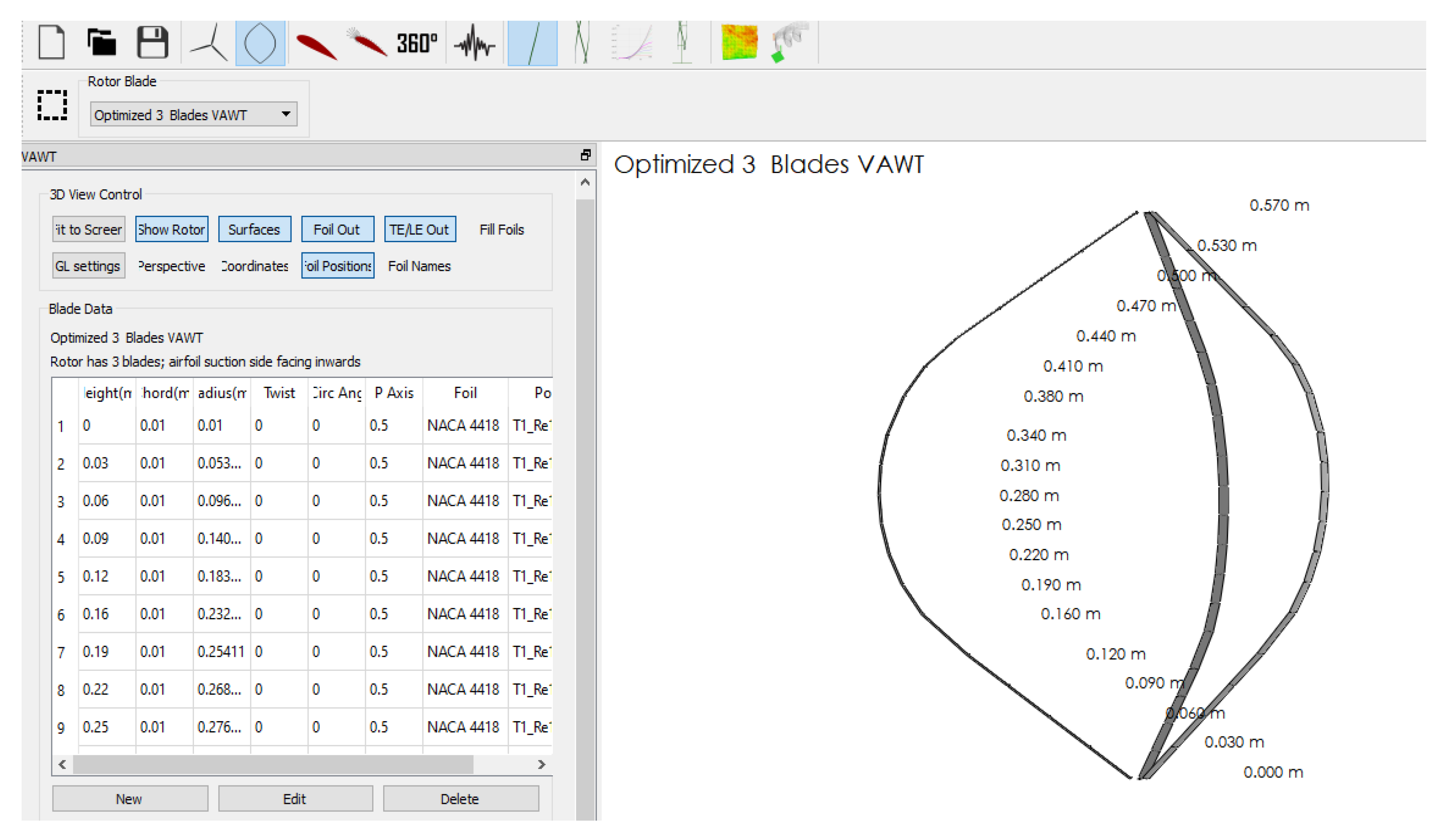
In order to obtain the model of the rotor and the design for different VAWT types, the NACA4418 for the blade was selected as shown in
Figure 3. Each blade divided to a finite number of blade sections. For each blade section, the design parameters of circumferential position, vertical position, radial position, length of the chord, and type of airfoil was introduced. All airfoil sections of straight blades have the same radius and circumferential position. In order to enhance the design of the blade of the vertical axis wind turbine and decrease the time consumption to find the results, scaling and optimization functionalities are used as illustrated in
Figure 4. These parameters are height scaling, height shifting, chord scaling, radius scaling, and twist scaling to speed up the rotor modification. The analyses were performed on the blade of the turbine within range (1 to 10 of tip speed ratio
λ). In this analysis, a constant velocity of 7 m/s was used, while the rotation of the rotor was varied concerning
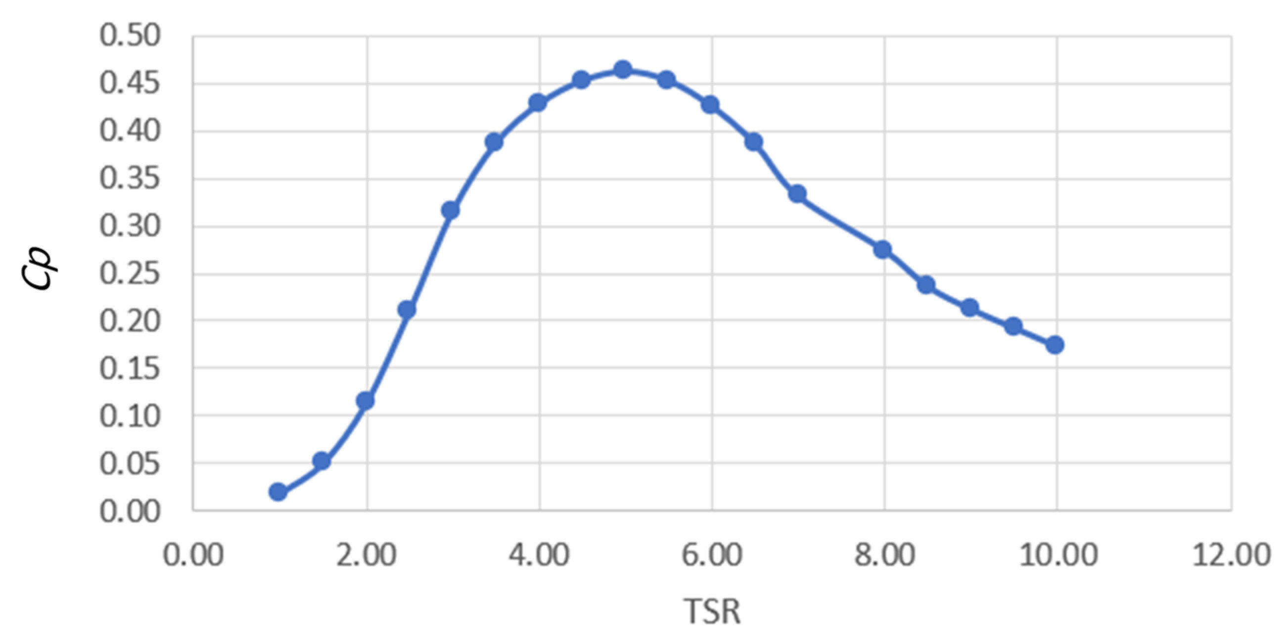
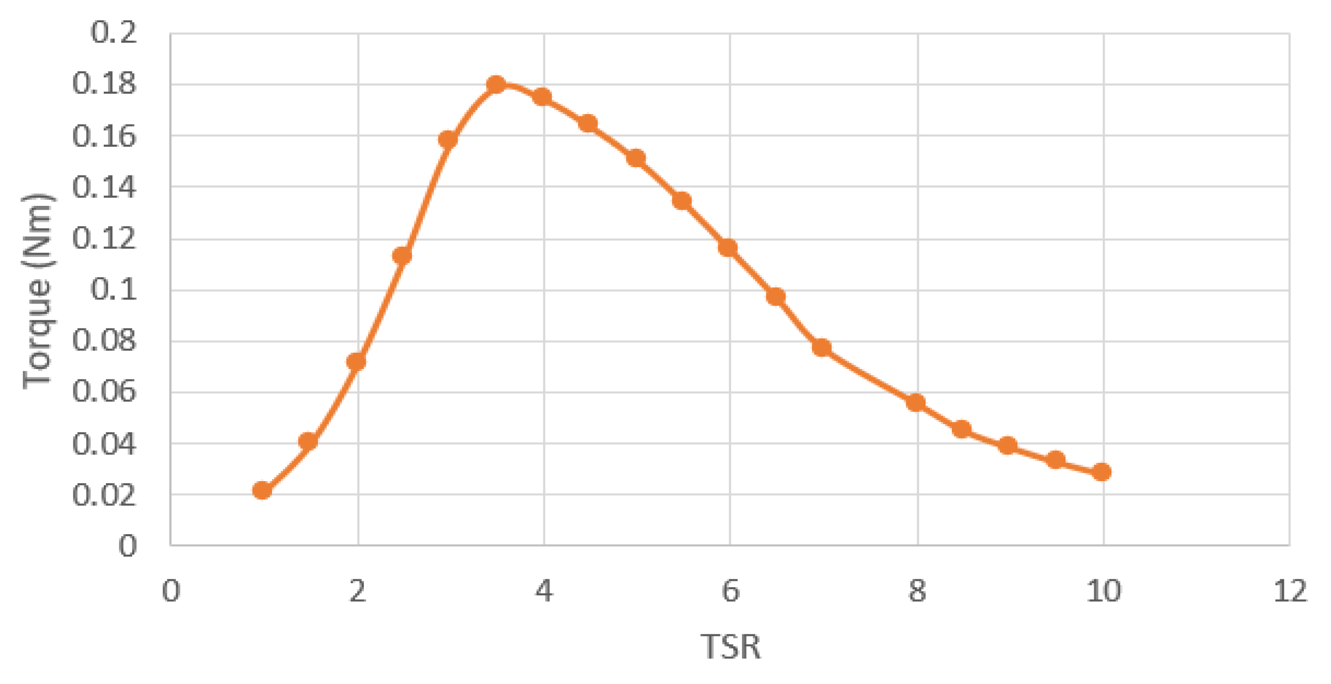
λ. As a result, the power coefficient and torque values vs. various tip speed ratios can be seen in
Figure 5 and
Figure 6, respectively. At low λ, the rotor does not spin and therefore, under such conditions, it cannot obtain power from the wind. There would be an acceptable value at the maximum power which is derived between λ = 1 and λ = 10. This would be the situation within the average speed of the rotor which is 2/3 of the wind speed in compliance with the Betz law. At the high value of λ, the rotor runs faster, and the chance to extract energy from the wind will decrease because the mass transports (wind) through the rotor will be reduced.
The optimum values of the design parameters were selected as inputs in the algorithm used in the software (DMS algorithm). During the computation process, it was assumed that the velocity of a free stream would be unified and it was used for the normalized dimensions of the rotor (height and radius).
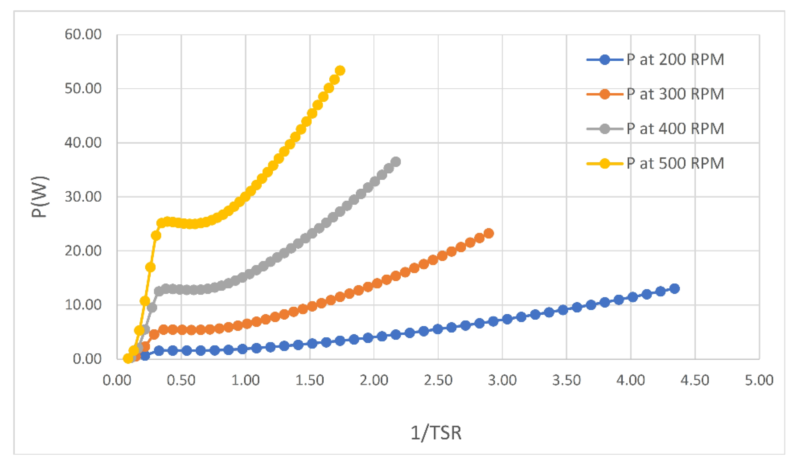
Furthermore, the graph type of DMS simulation is available to determine the multi- parameters as shown in
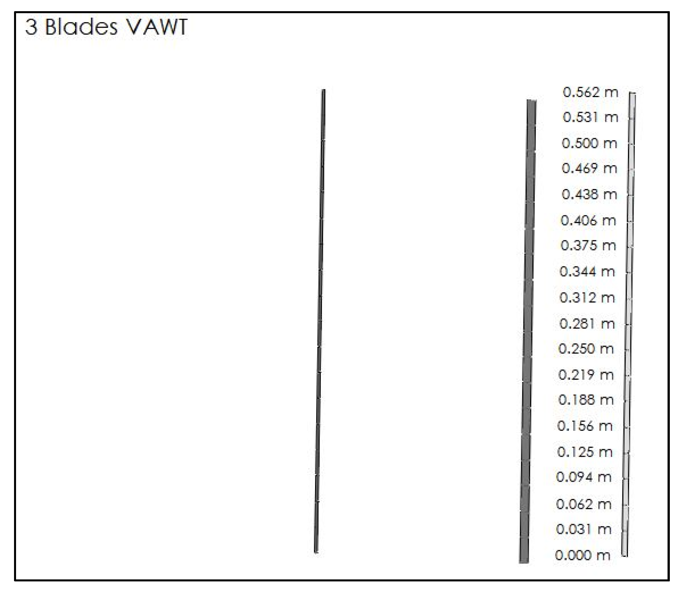
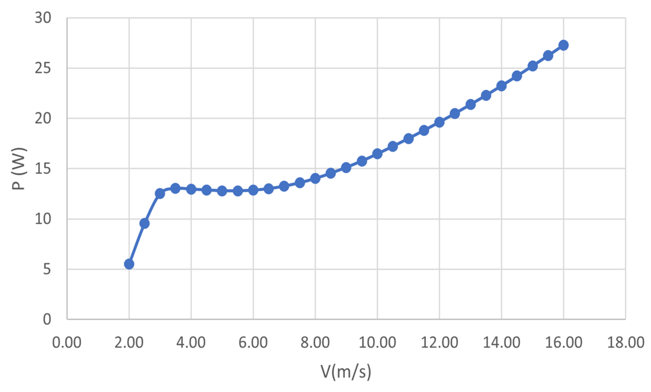
Figure 7. Power is not only dependent on the tip speed ratio but also on the rotational speed and pitch angle. For the range that started from 200 to 500 rpm with an increment of 100 of tip speed ratio TSR, four groups of results were obtained. It can be noticed that when power increased, the TSR increased, too. The power versus the wind speed was presented for 3 blades of VAWT using the simulation operation as shown in
Figure 8.
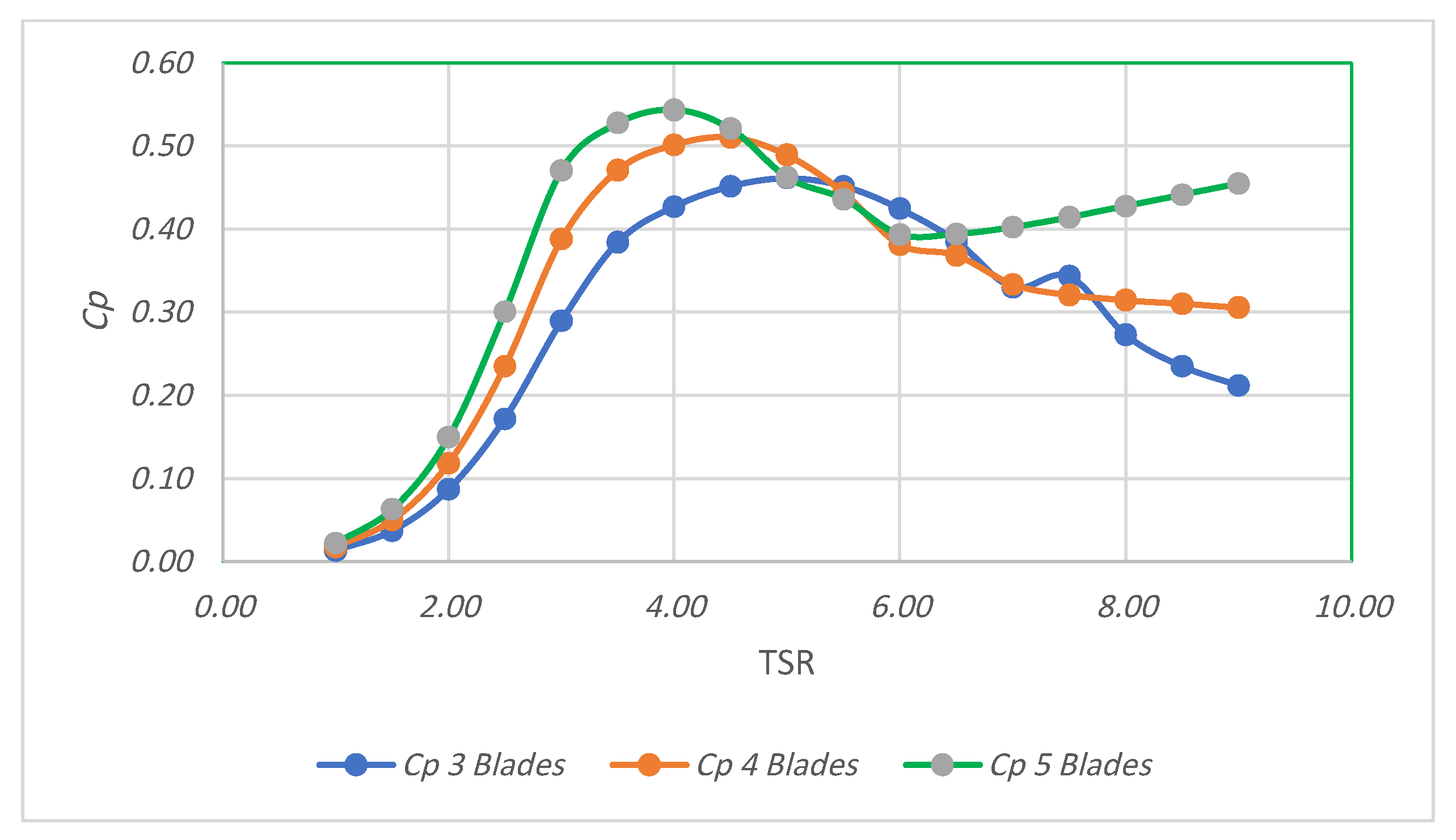
A rotor blade should be presented in the runtime database and parameters (rotor blade, cut-in and out wind speed, turbine offset, fixed and variable losses) of the wind that is to be specified to define the wind turbine. Comparisons between 3, 4, and 5 blades of VAWT rotor simulation were made as shown in
Figure 9. It was noticed that the coefficient of performance
Cp increased when the number of blades increased, too. The maximum values of
Cp were observed at TSR = 5 for the 3 blades (VAWT), and at TSR = 4.5 for the 4 blades (VAWT), while the maximum
Cp recorded for the 5 blades of VAWT was at TSR = 4. Additionally, it can be noticed that when using 5 blades, the values of
Cp (after maximum value) are decreased until TSR = 6 and then increased. While for the other cases (3 and 4 blades), the values of
Cp decreased gradually.
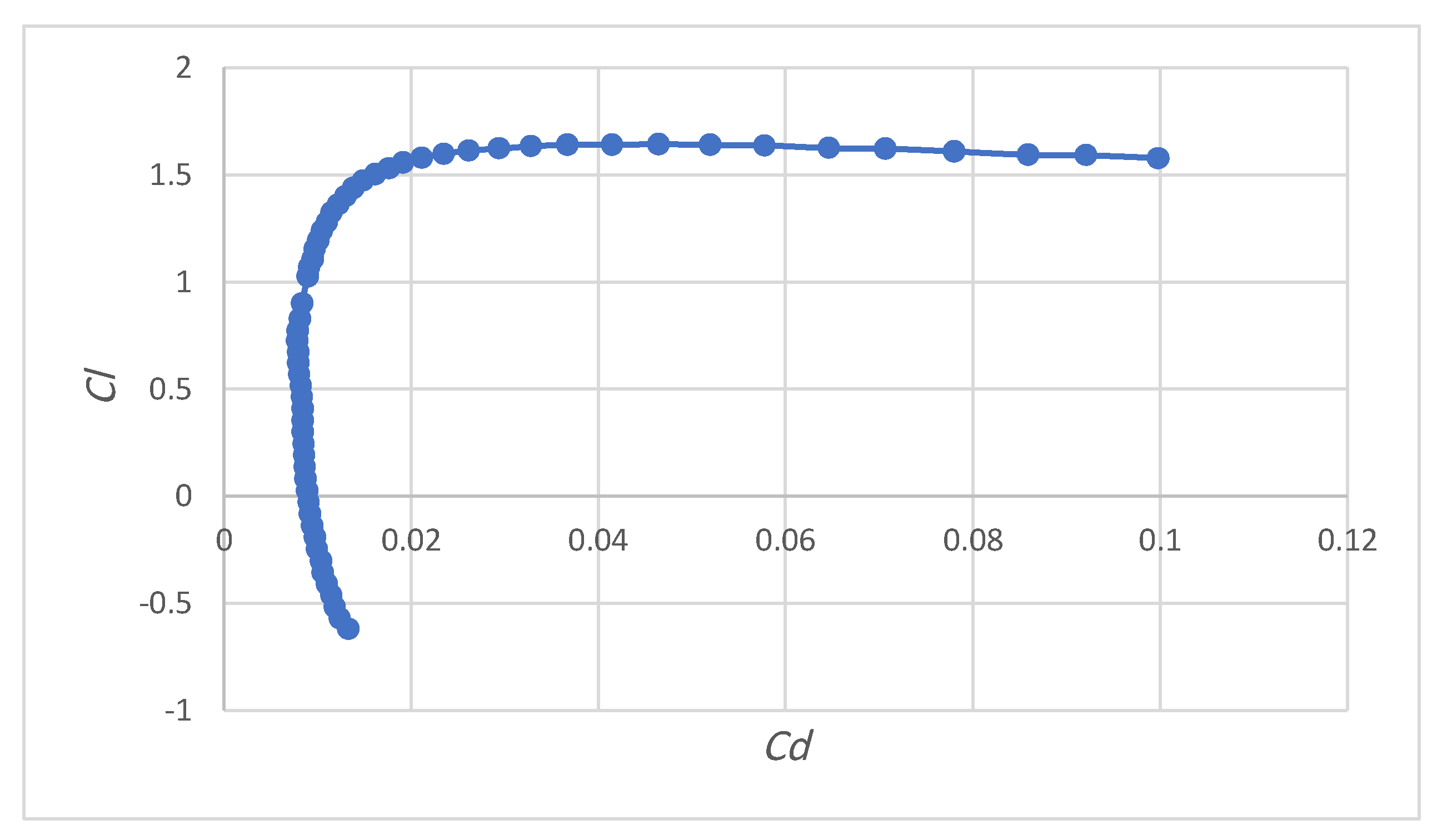
Figure 10 shows the change of lift coefficient with drag coefficient for 3 blades of VAWT using XFOIL direct analysis in QBlade.
6. Conclusions and Remarks
In this research paper, the full details were presented to obtain the optimal design to enhance the output power of the vertical axis wind turbine using QBlade software. The study focused mainly on finding the optimal values of the design parameters of VAWT blade airfoil. The helical blade is produced using the sub-module blade design and optimized using NACA4418 blade airfoil. Significant influence of the number of blades on the performance of the vertical axis wind turbine was found. It was concluded that 4 blades of turbine rotor are more efficient than the rotor turbine with 3 blades of rotor. On the other hand, the 5-blade turbine rotor showed better efficiency than the 3-blade model, but it failed for the condition of TSR greater than 9. Additionally, it was found that the power increased at the high rotational speed (500 rpm). The maximum power coefficient of the 3 blades VAWT was identified at TSR = 5.
This work is considered the first step in the project to study and analyze the vertical axis wind turbines, and it will be followed by other research that will study other types and designs of wind turbines in different promised sites.


 ,
, 


