Article

Robust Controller Decorated by Nonlinear S Function and Its Application to Water Tank

Ship Dynamic Simulation and Control Laboratory, Navigation College, Dalian Maritime University, Dalian 116026, China
*
Author to whom correspondence should be addressed.
Appl. Syst. Innov. 2021, 4(3), 64; https://doi.org/10.3390/asi4030064
Submission received: 12 July 2021 / Revised: 19 August 2021 / Accepted: 31 August 2021 / Published: 7 September 2021
(This article belongs to the Section Control and Systems Engineering)

Abstract

:
In this manuscript, a concept of modifying the results of the existing robust controller decorated by a nonlinear S function is presented to improve the system performance. A case-based study of level control of water tanks illustrates the effectiveness of nonlinear decoration in improving robustness and controlling energy-saving performance with an S-function-decorated robust controller. The performance of the controlled system was analyzed through Lyapunov stability theorem and robust control theory, and was evaluated with a performance index. By demonstrating three comparing simulations of different scenes, it testifies to the fact that the nonlinear decorated robust controller meets the requirement of improving the system performance index. Compared with the nonlinear feedback and the fuzzy control, the performance index of the system using a nonlinear decorated controller is reduced by more than 10% with satisfactory robustness. This nonlinear decorated robust controller is proven to be energy efficient, simple and clear and easy to use, valuable for extensive application.

1. Introduction

The level control of water tanks is a benchmark problem in the control field that can be used to assess the performance of a new control algorithm [1]. It is extensively used in many industrial fields. In particular, ocean vessels have a large number of liquid tanks, such as ballast tanks, oil tanks, fresh water tanks, and sludge tanks. They perform different services to guarantee safe navigation. Automatic control first originated from the needs of industrial processes. Since then, this technology has been developed for more than 70 years and has penetrated into every aspect of human life. However, in recent decades, the research on improving controller design has entered a bottleneck stage; there are hardly any new breakthroughs.
The development of control theory can be roughly divided into three stages: manual control, open-loop control and closed-loop control, and the closed-loop controls have transferred from process control to state control where the essence is still linear feedback [2]. If we use formulas to denote the closed-loop control then u = f ( e ) e (where u represents the controller output, e represents the system error). The effectiveness of control law f ( e ) is judged by whether the output will reach the set value when the system error occurs for a variety of reasons. Moreover, the conventional error feedback is linear feedback, which means e is feedback to the input of the controller either intact or filtered. Therefore, sometimes the control input is unnecessarily large. For this reason, several research studies attempted to use nonlinear feedback to replace linear feedback [3,4], that is u = f ( e ) g ( e ) ( g is a nonlinear function). Along the same lines, one can also adjust the control law output, which is called nonlinear decoration with h ( u ) = f ( e ) e (where h is a nonlinear function) [5,6]. The nonlinear-decorated control can improve system performance; therefore, the relevant research is worth to be conducted.
Reference [7] explained the four typical working conditions of water level fluctuations in surge tanks, and a cascade load regulation method for optimal attenuation of water level fluctuation under superposition conditions was proposed. Reference [8] discussed the design of PLC-based fractional-order controller for volume control of industry water tank; the purpose was to verify the stability and robustness of fractional-order discrete PID-feedback-loop for different approximation methods and approximation orders. Reference [9] introduced the improved smith predictor and the improved inverse calculation method to design the controller of the conical tank level process and compared the energy utilization and performance of the actuator in a nonlinear process with traditional PI controller. In order to stabilize the well water level, Dariusz also designed another PI controller [10]. The principle and algorithm of dynamic matrix predictive control are described in [11]. Through the experimental analysis of different models of single, double and triple tanks, a classical double tank model was proposed, which was shown to have great efficiency improvement in the control process compared to the conventional model.
In addition, Reference [12], using nonlinear ordinary differential equations described two mathematical models in order to research the adaptive control of nonlinear systems. Nonlinear robust controllers have also been widely used in other fields. However, all of the references mentioned above were in-depth studies based on different opinions and achieved some results about water tank control on the basis of distinctive control methods. Yet, there is little research based on the orientation of energy efficiency, leading to some prospective potential in this aspect.
On the basis of the references [13,14], the contributions of this paper are mainly twofold: (1) the condition of robust controller solution in reference [14] is reproved by using H theory, and the condition of robust performance is relaxed from 0 T 1 1 to T 1 > 0 ; (2) the nonlinear feedback based on the arctangent function in [13] is changed to the nonlinear decoration based on S function and the control performance is further improved.

2. Mathematical Model

Reference [15] puts forward one special case of concise robust control which is known as PID control. Undoubtedly, simplicity, reliability and obvious physical meaning are the typical features of PID control with extensive application in industrial control engineering. As a result, in order to reach better self-adaption, robustness, accuracy, and easier to regulate parameters, the typical PID control has been improved and modified into different modes gradually, e.g., self-adaptive PID control, self-tuning PID control, gain scheduling PID control, robustness PID control, etc., [15,16,17].
According to references [18,19], designing a controller using robust control theory has received more attention to, and it will be better to use the closed-loop gain shaping method to maintain the robustness of controllers [19,20,21,22].

2.1. Mathematic Model and Calculation of Parameters

If the controlled plant G can be shown as the second-order strictly appropriate plant of (1):
G = b 0 a 2 s 2 + a 1 s + a 0
Then, the robust controller K can be designed according to the closed-loop gain shaping algorithm as (2) [2].
K = a 2 s 2 + a 1 s + a 0 b 0 T 1 s = a 1 b 0 T 1 + a 0 b 0 T 1 s + a 2 s b 0 T 1
where 1 / T 1 is the frequency of system bandwidth.

2.2. Application of Robust Control in the Level Control of Water Tank

2.2.1. Mathematic Model of Water Tank

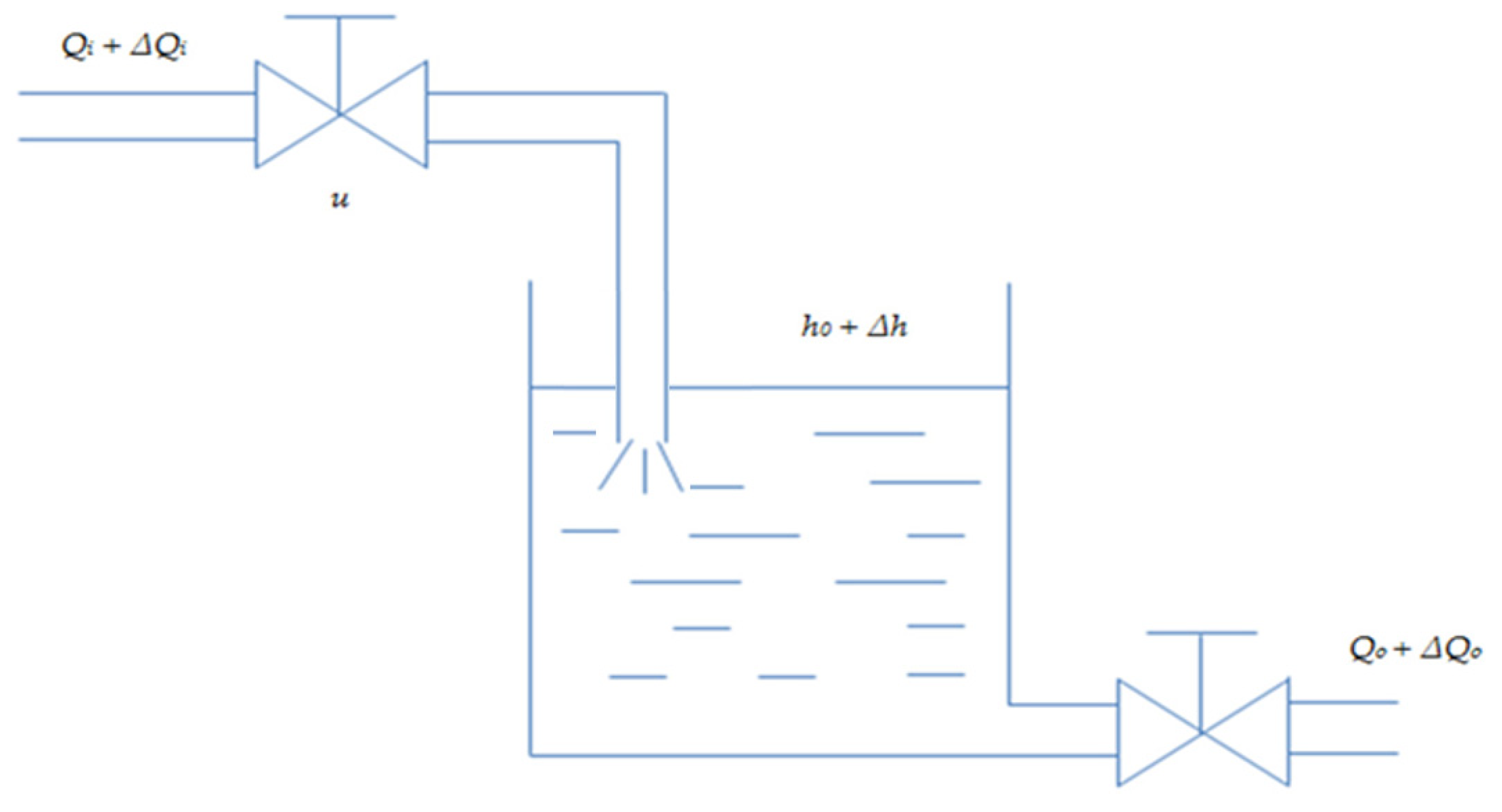
Figure 1 shows a simplified physical model; the switch sign indicates the water pump. In a single tank system (Figure 1), Q i indicates the steady-state value of input water flux, and Δ Q i means the increment of input water flux. Q o indicates the steady-state value of output water flux, and Δ Q o means the increment of output water flux. h means the height of water level, and h o means the steady-state value of water level, Δ h is the increment of the water level. u is the opening value of the adjustable input valve. A is the cross sectional area, R is the water resistance at the output valve, and V is the water volume in the tank. According to the correlation of material balance, the initial tank balance is displayed as: Q o = Q i ,   h = h o . When the adjustable input valve has an increment Δ u , the actual water level will change correspondingly. Thus, the output water flux will change, which is mainly caused by the variety of water levels while keeping the other output valves unchanged.
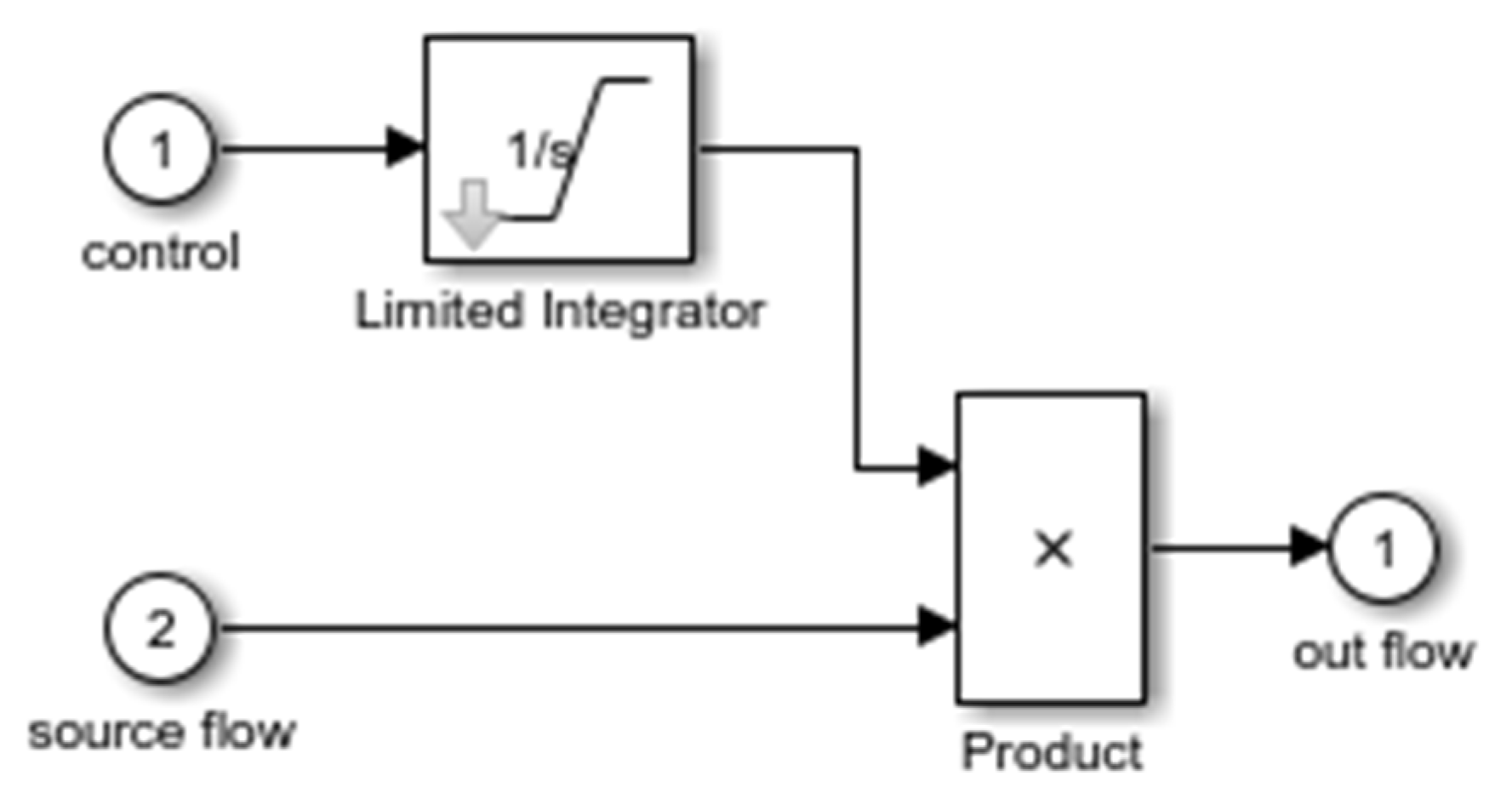
In this manuscript, the tank model is a first-order inertial system, and the tank inlet control valve model is equivalent to an integral, as shown in (Figure 2 and Figure 3)
The difference between the input and output water flux is
Δ Q i Δ Q o = d V d t = A d Δ h d t
In Formula (3), Δ Q i is caused by Δ u , then
Δ Q i = K u Δ u
where K u is the constant of water flow of valve.
The output water flow is relevant with the height of the water level, A 0 is the cross-sectional area of the output pipe, shown as
Q o = A o 2 g h
The above formula can be further linearized at the balance point ( h o , Q o ) , then
R = Δ h Δ Q o
We can substitute the Formulas (4) and (6) into (3), and adopt Laplace transformation to obtain the transfer function for a single water tank
G ( s ) = H ( s ) Q i ( s ) = K 0 s ( T 0 s + 1 )
where K 0 = K u R ,   T 0 = R A . The linear model of (7) is used to design the controller and the nonlinear model of (3)~(5) is used as the simulative model to test the robustness of the designed controller.
If we assume the parameters of a water tank are: the height of the tank is 2   m , the area of the tank base is 1   m 2 , the sectional area of the pipe is 0.05   m 2 , the initial water level is 0.5   m , and the max inlet ratio of water intake is 0.5   m 3 / s . Then, the formula of water level and inlet ratio is
G ( s ) = H ( s ) Q i ( s ) = K 0 s ( T 0 s + 1 ) = 0.8 s ( 2 s + 1 )
where H represents the water level in the tank, and Q i represents the input flux ratio.
Formula (7) can also be shown as
T 0 H ¨ + H ˙ = K 0 Q i
If taking the disturbance term into consideration (interference is used to prove the stability of the system.), then Formula (9) can be improved as
T 0 H ¨ + H ˙ = K 0 Q i + w
where the w is limited disturbance term, and also w ρ .

2.2.2. Controller Design Based on the Closed-Loop-Gain Algorithm

According to Formula (7), the closed-loop gain algorithm was used in the controller design (as Figure 4). If 1 / T 1 = 1   rad / s , all parameters of robust controller can be obtained as k p = 1 0.8 ,   k i = 0 ,   k d = 2 0.8 . This study emphasizes on the application of the nonlinear S function 1 e 2 u 1 + e 2 u in modifying the output of the controller mathematically and experimentally. The new PD controller, improved by the S function, which is proved by its result in improving the controller performance.

3. Controller Design

In this study, the Lyapunov stability theory was applied to launch the stability analysis of the water tank feedback controller, which is designed based on the closed-loop-gain algorithm.
First, the state variable of the control system is interpreted as X = [ x 1 x 2 ] T ,
{ x 1 = e x 2 = x ˙ 1 = H ˙
Based on Formula (11), the inlet ratio of the water tank control system can be expressed as (12). At the same time, the parameters’ values are a 1 = 1 ,   a 0 = 0 ,   a 2 = 2 ,   b = 0.8 . Combine with (2).
Q i = K e = 1 K 0 T 1 e + T 0 K 0 T 1 e ˙
By combining Formulas (8) and (12), we obtain:
T 0 H ¨ + H ˙ = K 0 ( 1 K 0 T 1 e + T 0 K 0 T 1 e ˙ ) + w
Then, by rearranging Formulas (11) and (13), the state equation of the controlled system can be written as
X ˙ = A X + b w
For Formula (14), the Lyapunov function of the system is interpreted as
V ( x ) = X T P X
where P represents a positive definite real symmetric matrix, and P = P T .
Ignoring the external disturbance term w , then
V ˙ ( x ) = X T P A X + ( A X ) T P X = X T ( P A + A T P ) X
According to the Lyapunov stability theory, the following function is needed to ensure the stability of the system at origin, for any interpreted positive definite real symmetric matrix.
A T P + P A = Q
Define positive definite real symmetric matrix, and make positive definite real symmetric matrix P as
P = [ P 11 P 12 P 12 P 22 ]
Putting Formulas (14) and (18) into Formula (17), to obtain
[ 0 1 T 0 T 1 1 T 1 + T 0 T 0 T 1 ] [ P 11 P 12 P 12 P 22 ] + [ P 11 P 12 P 12 P 22 ] [ 0 1 1 T 0 T 1 T 1 + T 0 T 0 T 1 ] = [ 1 0 0 1 ]
To expand Formula (19) and obtain the solutions as
{ P 11 = ( T 1 + T 0 ) 2 + ( 1 + T 0 T 1 ) 2 ( T 0 + T 1 ) P 12 = T 0 T 1 2 P 22 = T 0 T 1 ( 1 + T 0 T 1 ) 2 ( T 0 + T 1 )
The following functions have to be met for maintaining the positive definiteness of matrix P
{ P 11 > 0 P 11 P 22 P 12 2 > 0
By solving Function (21), we obtain
{ T 1 > 3 T 0 + 5 T 0 2 4 2 T 0 T 1 > 0
Thus, in the case of T 0 > 0.8 = 0.9 , if T 1 > 0 is ensured, then the controller will keep the balanced state at the origin.
For the purpose of verifying the robustness of the controller proposed by this study against external distraction, the external distraction term w is considered in Formula (9), and then the formula of Lyapunov function as shown in Formula (10), is [14]
V ˙ ( x ) = x 1 2 x 2 2 T 1 w x 1 k w x 2
where k = T 1 ( 1 + T 0 T 1 ) / ( T 1 + T 0 ) .
According to Young’s inequality, we can obtain
{ w T x 1 T 1 2 x 1 2 + w 2 4 k w x 2 k 2 x 2 2 + w 2 4
Then, ω is a bounded interference term and ω ρ .
V ˙ ( x ) = ( 1 T 1 2 ) x 1 2 ( 1 T 1 2 ) x 2 2 + w 2 2 ( 1 T 1 2 ) x 1 2 ( 1 k 2 ) x 2 2 + ρ 2 2
To define a = max ( T 1 , k ) , then
V ˙ ( x ) ( 1 a 2 ) X T X + ρ 2 2
Formula (26), indicated that when state variable of the system X > ρ / 2 ( 1 a 2 ) , then V ˙ ( x ) < 0 .
For further discussing the robustness for the external distraction, L 2 which is the performance index of gain robust is interpreted as
0 t X 2 d t μ 1 0 t w 2 ( t ) d t + μ 2
where μ 1 and μ 2 are positive and small, and the following theorem is obtained.
Theorem: in the controller design for the water tank level control system, as shown in Formula (14) by applying the closed-loop gain algorithm, and the parameter T 1 of controller satisfying the condition of 0 < T 1 1 , the state variable of the system X > ρ / 2 ( 1 a 2 ) ensures the whole controller uniform ultimate boundness and also achieves the performance index of gain robust L 2 , which is related to the controller parameter T 1 .
This theorem can be proved by integrating Formula (26) from t = 0 to t = t 0 , to obtain
V ( t 0 ) + ( 1 a 2 ) 0 t 0 X T X d t 1 2 0 t 0 w ( t ) T w ( t ) d t V ( 0 )
On the basis of the definition of, Formula (28) can be derived as
0 t 0 X 2 d t 1 2 ( 1 a 2 ) 0 t 0 w 2 ( t ) d t + 1 1 a 2 ε
After discussing the bounds of a as shown in Formula (29), a can be stated as [22]
a = { T 1 , T 0 1 T 1 ( 1 + T 0 T 1 ) T 1 + T 0 ,   0 < T 0 < 1
The formula 1 a 2 > 0 is a requisite, for the purpose of keeping the negative definite of Formula (26), and then the range of controller parameters is derived according to Formula (30)
0 < T 1 1
To summarize, based on the result of the Formula (27) about the performance index of gain robust and Formula (29), when the state variable of water tank control system satisfies the requirement of X > ρ / 2 ( 1 a 2 ) , if the parameter T 1 of the controller of closed-loop gain control law can meet 0 < T 1 1 , then the water tank control system shown in Formula (14) will obtain the performance index of gain robust L 2 , as shown in Formula (27), which is 1 / 2 ( 1 a 2 ) related to the parameter of controller parameter T 1 .
If the S function is applied to decorate the output ( u ) of the existing controller, then
K = 1 e γ u 1 + e γ u
Based on the Taylor series expansion, the Formula (33) can be obtain
e γ u 1 γ u
Then
1 e γ u 1 + e γ u γ u 2 γ u
When u is not too large, then
1 e γ u 1 + e γ u 0.5 γ u
When γ = 1.5 , the above derivation is still valid.
The above proof is based on the reference [14] using the L 2 gain robustness performance index. In the actual simulation, it is found that the requirement 0 < T 1 < 1 is conservative and the H robust theorem is used to re-prove.
According to Formulas (11) and (14), if the output matrix C = [ 0 1 ] is added, the sensitivity function S = C ( s I A ) 1 B of the system can be obtained, followed by the complementary sensitivity function T of the system.
T = 1 S = T 0 T 1 s 2 + ( T 0 + T 1 ) s + 1 T 1 ( T 0 s + 1 ) ( T 1 s + 1 )
According to the system robustness theorem, Formula (37) can be obtained as
T w ρ
Derivable
T 1
According to Formula (36), if you want to satisfy Formula (38), the damping coefficient of a second-order oscillation system requiring a complementary sensitivity function is greater than or equal to 1.
T 0 + T 1 2 T 0 T 1 1
Therefore,
T 0 2 + T 1 2 2 T 0 T 1 0
According to Young’s inequality, it can be obtained that
2 T 0 T 1 T 1 2 + ( 2 T 0 ) 2 4 = T 1 2 + T 0 2
Therefore, Formula (39) is automatically satisfied; hence under the condition that the state variables of water tank level control system satisfy X > ρ / 2 ( 1 a 2 ) , as long as T 1 > 0 and T 0 > 0 , the robustness of the designed controller can be guaranteed, which is more relaxed than the original condition, and also consistent with the simulation results.

4. Simulation Experiments and Results

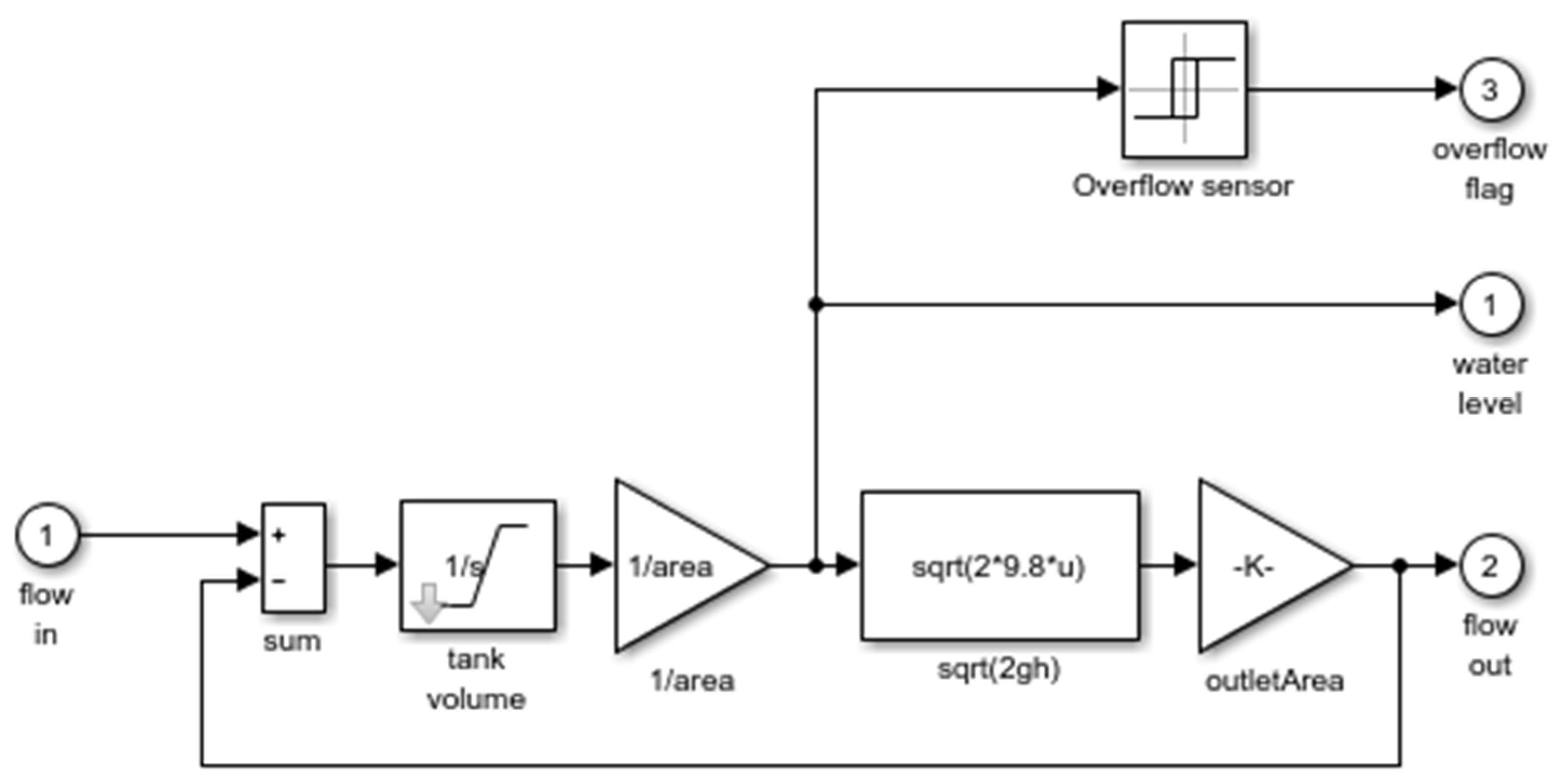
The Simulink toolbox of MATLAB (2016b) was used for the simulation experiment, and its diagrammatic drawing is shown in Figure 5. Compared with the fuzzy controller proposed in reference [18], the robust control proposed in reference [17] has better robust stability and simplicity. However, the improved PD controller proposed in this study is a kind of S function nonlinear decorated control, aiming to achieve energy-saving performance based on the two controllers mentioned above.
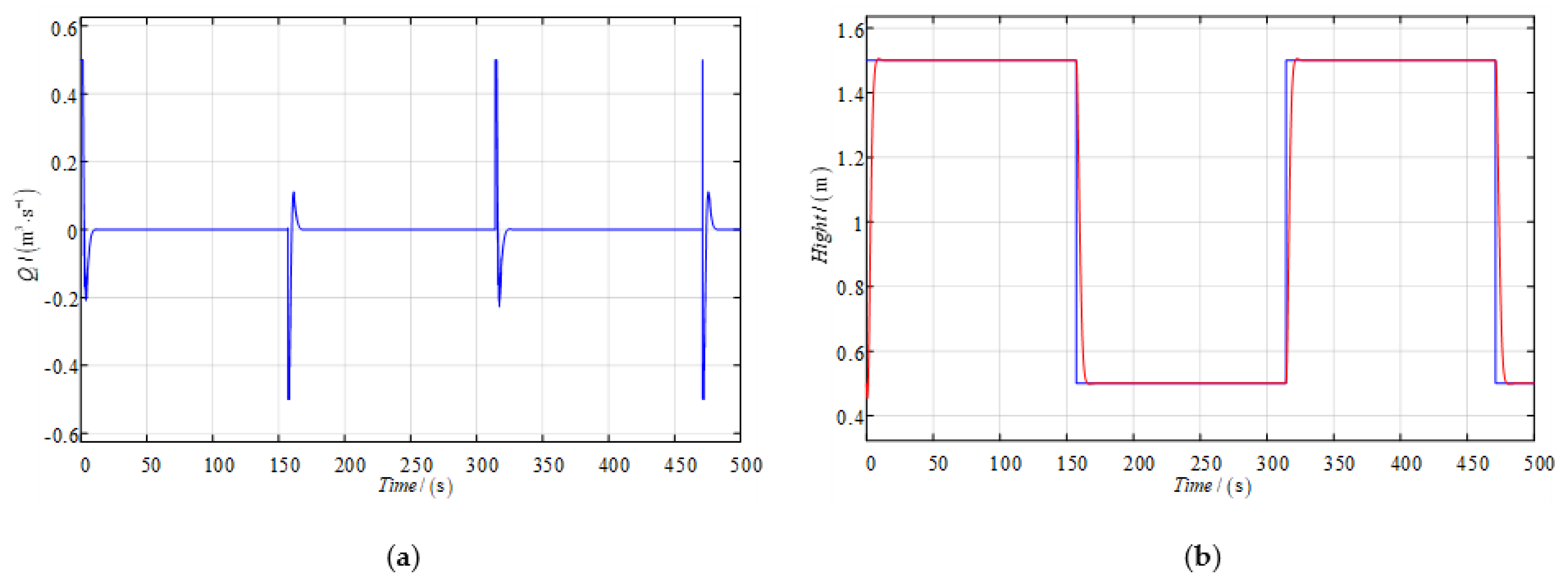
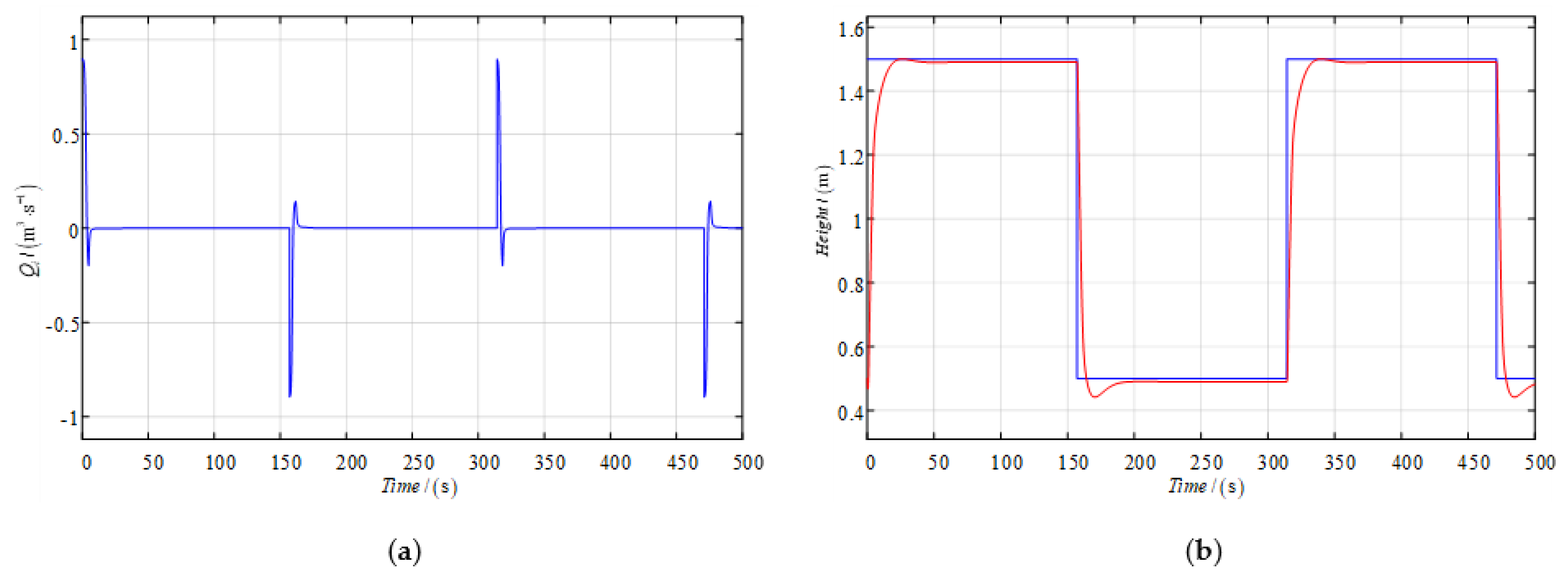
The input signal is a square wave with amplitude changing from 0.5   m to 1.5   m . The Formula (2) in this study was applied to design a PD controller. When the max inlet ratio of the tank is ensured at 0.5   m 3 / s due to the effect of nonlinear decorated robust PD control, the mean control input is 0.0273   m 3 / s . The simulation results are displayed in Figure 6. There are no overshoot and quick tracking achieved. Considering the complicated nonlinear model that is used in the simulation experiments while the controller is designed according to the simplified linear model, the system robustness is also guaranteed. (In Figure 6b, the blue line represents the set level and the red line represents the simulated level).
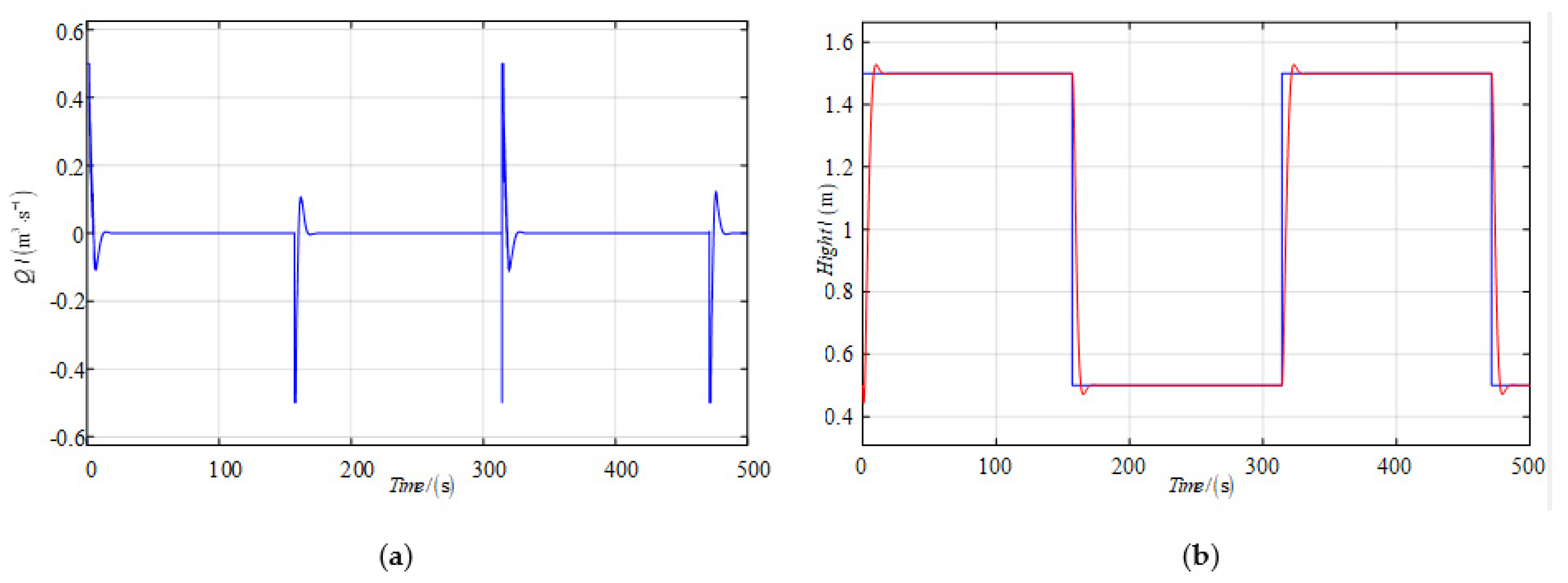
As displayed in Figure 7, which shows the effect of nonlinear feedback, its mean control input is 0.0302   m 3 / s . The control input of the improved algorithm is reduced by 9.6%, compared to the nonlinear-decorated control and the nonlinear feedback control. The purpose of saving energy by applying the S-function-decorated control is then obtained.
The mean control input of nonlinear decorated robust control is 0.0349   m 3 / s if the inlet ratio is decreased from 0.5   m 3 / s to 0.4   m 3 / s , as shown in Figure 8. The control output of the level is almost unchanged with satisfactory robustness.
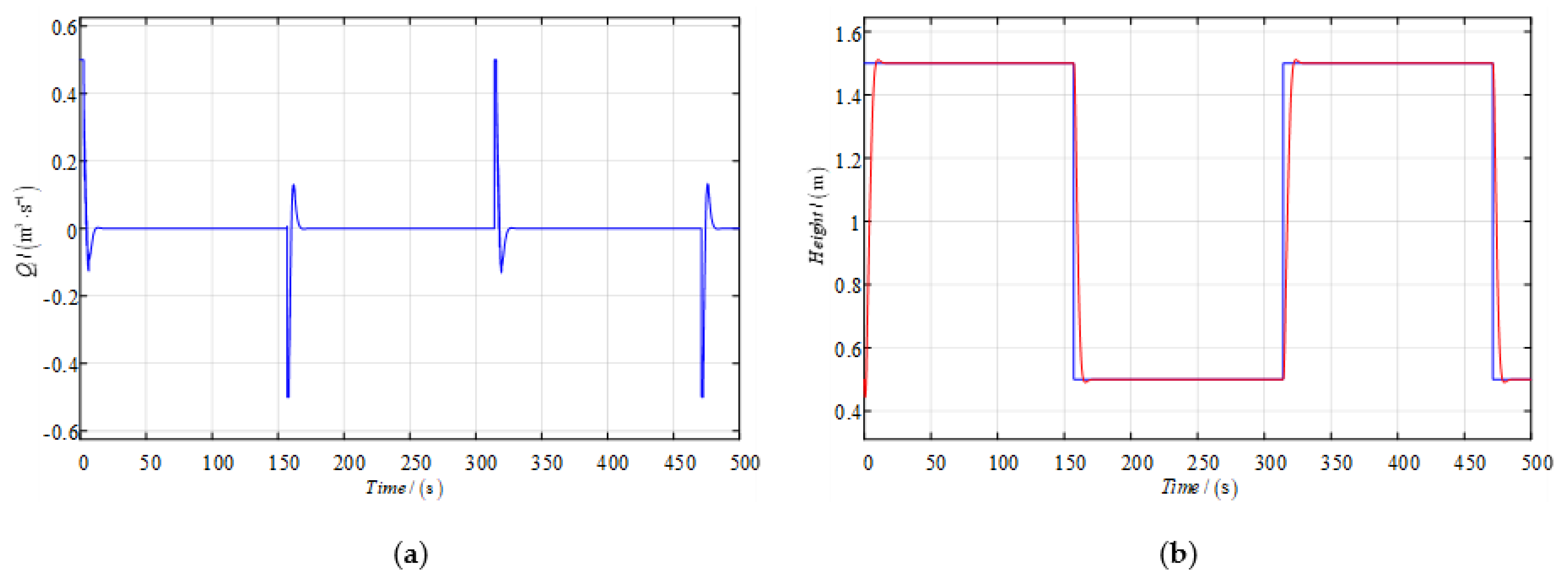
The effect of nonlinear feedback is shown in Figure 9, its mean control input is 0.0365   m 3 / s when the inlet ratio is reduced from 0.5   m 3 / s to 0.4   m 3 / s . Compared with the nonlinear-decorated control and the nonlinear feedback control with a limited inlet ratio, the control input of the improved algorithm is reduced by 4.4%.
The performance of linear feedback fuzzy control is displayed in Figure 10, the mean control input is 0.0369   m 3 / s , and the effect of linear feedback fuzzy control is displayed in Figure 11 when the limit of inlet ratio is 0.4   m 3 / s , with the mean control input as 0.0421   m 3 / s . The mean control input of nonlinear-decorated robust control is reduced by 26.1%, compared with the linear feedback fuzzy control. The purpose of energy-saving is met. Further, the fuzzy control has a slight overshoot.
The comprehensive control performance index J of (42) is used to evaluate the above three kinds of control algorithms.
J = ( Q i 2 + Δ H 2 ) d t
J is a function that controls input energy and output error, and the smaller the value is, the better. Table 1 presents a quantitative comparison of the control simulation results mentioned above, and studies the efficiency of the proposed algorithm. It is worth nothing that the response performance specification J of the nonlinear-decorated robust method is decreased by 13.0% and 26.3%, respectively, in contrast to the nonlinear feedback and the fuzzy controller. When the model has some perturbation (the max inlet ratio is changed), the control performance is also satisfactory with good robustness.
5. Conclusions

Through comparing experiments, the control algorithm resulting in the nonlinear decorated robust control has the best system performance index, which can reduce the system performance index up to 13.0% and 26.3%, respectively, compared with the nonlinear feedback and the fuzzy control. The improved controller presented in this study is based on the robust controller proposed in reference [15], when properly preserving its notable robust stability and concision. The most important advantage of the improved edition is its remarkable energy-saving competence. This achievement results from the introduction of the S function to nonlinear-decorated-control to achieve the energy-saving target. The modification method analyzed in this study can be applied to other cases in the engineering industry on a larger scale.

Author Contributions

Conceptualization, X.Z. and C.S.; methodology, X.Z.; software, C.S.; validation, C.S. Both authors have read and agreed to the published version of the manuscript.

Funding

This work is partially supported by the National Science Foundation of China (Grant No.51679024), the Fundamental Research Funds for the Central University (Grant No.3132016315), and the University 111 Project of China (Grant No. B08046).

Conflicts of Interest

The authors declare no conflict of interest.

References

  1. Mystkowski, A.; Kierdelewicz, A. Fractional-Order Water Level Control Based on PLC: Hardware-in-the-Loop Simulation and Experimental Validation. Energies 2018, 11, 2928. [Google Scholar] [CrossRef] [Green Version]
  2. Zhang, X.K.; Jin, Y.C. Control System Modeling and Numerical Simulation, 2nd ed.; Dalian Maritime University Press: Dalian, China, 2013. [Google Scholar]
  3. Zhang, Q.; Zhang, X.-K.; Im, N.-K. Ship nonlinear-feedback course keeping algorithm based on MMG model driven by bipolar sigmoid function for berthing. Int. J. Nav. Arch. Ocean Eng. 2017, 9, 525–536. [Google Scholar] [CrossRef]
  4. Zhang, X.; Yang, G.; Zhang, Q.; Zhang, G.; Zhang, Y. Improved Concise Backstepping Control of Course Keeping for Ships Using Nonlinear Feedback Technique. J. Navig. 2017, 70, 1401–1414. [Google Scholar] [CrossRef]
  5. Song, C.; Zhang, X.; Zhang, G. Nonlinear Identification for 4 DOF Ship Maneuvering Modeling Via Full-Scale Trial Data. IEEE Trans. Ind. Electron. 2021, 99, 1. [Google Scholar] [CrossRef]
  6. Zhang, X.; Han, X.; Guan, W.; Zhang, G. Improvement of integrator backstepping control for ships with concise robust control and nonlinear decoration. Ocean Eng. 2019, 189, 106349. [Google Scholar] [CrossRef]
  7. Guo, W.; Wang, B.; Yang, J.; Xue, Y. Optimal control of water level oscillations in surge tank of hydropower station with long headrace tunnel under combined operating conditions. Appl. Math. Model. 2017, 47, 260–275. [Google Scholar] [CrossRef]
  8. Arkadiusz, M.; Argyrios, Z. Plc-based discrete fractional-order control design for an industrial-oriented water tank volume system with input delay. Fract. Calc. Appl. Anal. 2018, 21, 1005–1026. [Google Scholar]
  9. SarathYadav, E.; Indiran, T. Comparative approach toward modified smith predictor and back calculation design for conical tank level process control. In Lecture Notes in Mechanical Engineering; Springer: Singapore, 2017; pp. 569–577. [Google Scholar]
  10. Dariusz, B. Water level control of a small hydropower plant with a surge tank. J. Hydraul Res. 2017, 55, 284–291. [Google Scholar]
  11. Zhong, X.; Peng, L.X.; Yi, C.; Zhang, J. The research on intelligent prediction algorithm for water level control of tank. J. Nonlinear Convex A 2009, 20, 1271–1281. [Google Scholar]
  12. Jiri, V.; Petr, D. Simulation of Adaptive LQ Control of Nonlinear Process. Stud. Inf. Contro 2012, 20, 215–324. [Google Scholar]
  13. Zhao, J.; Zhang, X. Inverse Tangent Functional Nonlinear Feedback Control and Its Application to Water Tank Level Control. Processes 2020, 8, 347. [Google Scholar] [CrossRef] [Green Version]
  14. Guan, W.; Zhou, Q.H.; Ren, Z.H.; Teng, B. The USV concise robust course control based on planning and control scheme. J. Harbin Eng. Univ. 2019, 40, 1801–1808. [Google Scholar]
  15. Zhang, X.K. Ship Motion Concise Robust Control; Science Press: Beijing, China, 2012. [Google Scholar]
  16. Zhang, X.K.; Jin, Y.C.; Zhang, X.-K.; Jin, Y.-C. Robust PID controller based on closed-loop gain shaping algorithm and its application. In Proceedings of the 2009 International Conference on Machine Learning and Cybernetics, Baoding, China, 12–15 July 2009. [Google Scholar]
  17. Zhang, X.K.; Jia, X.L. Robust PID Algorithm based on Closed-loop Gain Shaping and its application on level control. Shipbuild. China 2000, 41, 35–38. [Google Scholar]
  18. Zhang, X.; Zhang, Q.; Ren, H.X.; Yang, G.P. Linear Reduction of Backstepping Algorithm Based on Nonlinear Decoration for Ship Course-keeping Control System. Ocean. Eng. 2018, 147, 1–8. [Google Scholar] [CrossRef]
  19. Shi, S.; Cong, S.; Zhang, Z. A design method for robust PID controller based on structured singular value. J. Shanghai Jiao Tong Univ. 1995, 25, 1–5. [Google Scholar]
  20. Ning, X.; Zhang, Y.; Wang, Z. Robust Adaptive Control for a Class of T-S Fuzzy Nonlinear Systems with Discontinuous Multiple Uncertainties and Abruptly Changing Actuator Faults. Complexity 2020, 2020, 8863073. [Google Scholar] [CrossRef]
  21. Zhao, Y.; Niu, B.; Jiang, X.; Zhao, P.; Wang, H.; Yang, D. Partial-State-Constrained Adaptive Intelligent Tracking Control of Nonlinear Nonstrict-Feedback Systems with Unmoulded Dynamics and Its Application. Complexity 2020, 2020, 8835454. [Google Scholar] [CrossRef]
  22. Zhang, G.; Zhang, X. Concise Robust Adaptive Path-Following Control of Underactuated Ships Using DSC and MLP. IEEE J. Ocean. Eng. 2014, 39, 685–694. [Google Scholar] [CrossRef]
Figure 1. Single water tank. Adapted with permission from [13].
Asi 04 00064 g001
Figure 2. Model of Inlet Control Valve for Water Tank. Adapted with permission from [18].
Asi 04 00064 g002
Figure 3. Tank model.
Asi 04 00064 g003
Figure 4. Standard feedback control system.
Asi 04 00064 g004
Figure 5. Simulation diagram of fuzzy controller and nonlinear robust controller decorated by S function.
Asi 04 00064 g005
Figure 6. Simulation results of nonlinear decorated robust controller: (a) represents the control input curve (b) represents the water level curve.
Asi 04 00064 g006
Figure 7. Simulation results of nonlinear feedback (0.5): (a) represents the control input curve (b) represents the water level curve.
Asi 04 00064 g007
Figure 8. Simulation results of nonlinear decorated robust control: (a) represents the control input curve (b) represents the water level curve.
Asi 04 00064 g008
Figure 9. Simulation results of nonlinear feedback (0.4): (a) represents the control input curve (b) represents the water level curve.
Asi 04 00064 g009
Figure 10. Simulation results of feedback fuzzy control: (a) represents the control input curve (b) represents the water level curve.
Asi 04 00064 g010
Figure 11. Limited inflow rate feedback fuzzy control simulation results: (a) represents the control input curve (b) represents the water level curve.
Asi 04 00064 g011
Table 1. Comparison of the Closed Loop Performance.
Maximum   Inflow   Rate   Is   0.5   m 3 / s Maximum   Inflow   Rate   Is   0.4   m 3 / s
Nonlinear decorated robust algorithm412.7534.3
Nonlinear feedback [13]474.6608.9
Fuzzy control algorithm560.1648.9
Variable rate to the nonlinear feedback (%) [13]13.0%12.3%
Variable rate to the fuzzy control algorithm (%)26.3%17.7%
Publisher’s Note: MDPI stays neutral with regard to jurisdictional claims in published maps and institutional affiliations.