Abstract
This work determines the coded control of a sectional electroelastic engine at the elastic–inertial load for nanomechatronics systems. The expressions of the mechanical and adjustment characteristics of a sectional electroelastic engine are obtained using the equations of the electroelasticity and the mechanical load. A sectional electroelastic engine is applied for coded control of nanodisplacement as a digital-to-analog converter. The transfer function and the transient characteristics of a sectional electroelastic engine at elastic–inertial load are received for nanomechatronics systems.
1. Introduction
The application of a multilayer electroelastic engine, a compound electroelastic engine, and a sectional electroelastic engine on the piezoelectric effect or the electrostriction effect are promising for nanomanipulators in nanotechnology [1,2,3]. To increase the range of the displacement, a multilayer electroelastic engine and a sectional electroelastic engine are used [4,5]. A multilayer electroelastic engine has lower control voltage, making it safer to use. Its piezolayers can be combined into sections [6]. A multilayer sectional electroelastic engine is used in nanotechnology and nanobiomedicine, adaptive optics, interferometers and laser research [7]. A sectional electroelastic engine solves tasks of precise nanopositioning adjustment for nanotechnology, adaptive optics, antennas and nanomechatronics systems [7,8,9].
This work uses the separation of an electroelastic engine into several sections to achieve more precise control and two-level voltage switching. The piezolayers are connected in parallel in each section. The number of piezolayers in a section is equal to 2 in the power of 0, 1, 2, 3, 4, and so on. A sectional electroelastic engine operates as a digital-to-analog converter. The tasks of providing the accuracy and speed of the control system using a nanopositioning sectional electroelastic engine with the coded control are topical. Studies of the mechanical and adjustment characteristics of a nanopositioning sectional electroelastic engine with the coded control are relevant for nanotechnology. In the scanning probe microscope and the gene manipulator, a sectional electroelastic engine is applied for the scanner and the nanomanipulator [7,10].
For nanomechatronics systems, the mechanical and adjustment characteristics of a sectional electroelastic engine are obtained. The transfer function and the transient response of a sectional electroelastic engine at elastic–inertial load are received.
2. Mechanical and Adjustment Characteristics of a Sectional Electroelastic Engine
Let us consider the mechanical and adjustment characteristics in the static of a sectional electroelastic engine for nanomechatronics systems at the transverse, longitudinal and shift piezoeffects. The piezolayers in a sectional electroelastic engine are connected in parallel in each section of a sectional electroelastic engine.
The control voltage is supplied to each section via the multiplexer. Several sections are connected via the multiplexer two-level control voltage in the forms 0 or U. In terms of statics, each section is deformed, and the movement of the section takes a minimum value at 0 voltage or a maximum value at U voltage.
A sectional electroelastic engine is used as a digital-to-analog converter-engine for nanodisplacement. The number of the piezolayers in the section is equal to the power of 2. To calculate the deformation of a sectional electroelastic engine, using the equations of the electroelasticity and the mechanical load is necessary. A sectional electroelastic engine consists of N sections with all n layers.
For a sectional electroelastic engine, the equation of the electroelasticity [10,11,12,13,14,15,16,17,18,19,20,21,22,23,24,25,26,27,28,29] has the form of the inverse piezoelectric effect
where , , , , and are the relative deformation, the coefficient of electroelasticity, the electric field strength, the elastic compliance with and the mechanical tension, respectively, with the indices , .
The mechanical characteristic of a sectional electroelastic engine has the form
where Δl, F, U, and are the deformation, the force, the voltage and the binary code for the k section, respectively.
The adjustment characteristic of a sectional electroelastic engine at elastic load has the form
where is the rigidity of the load.
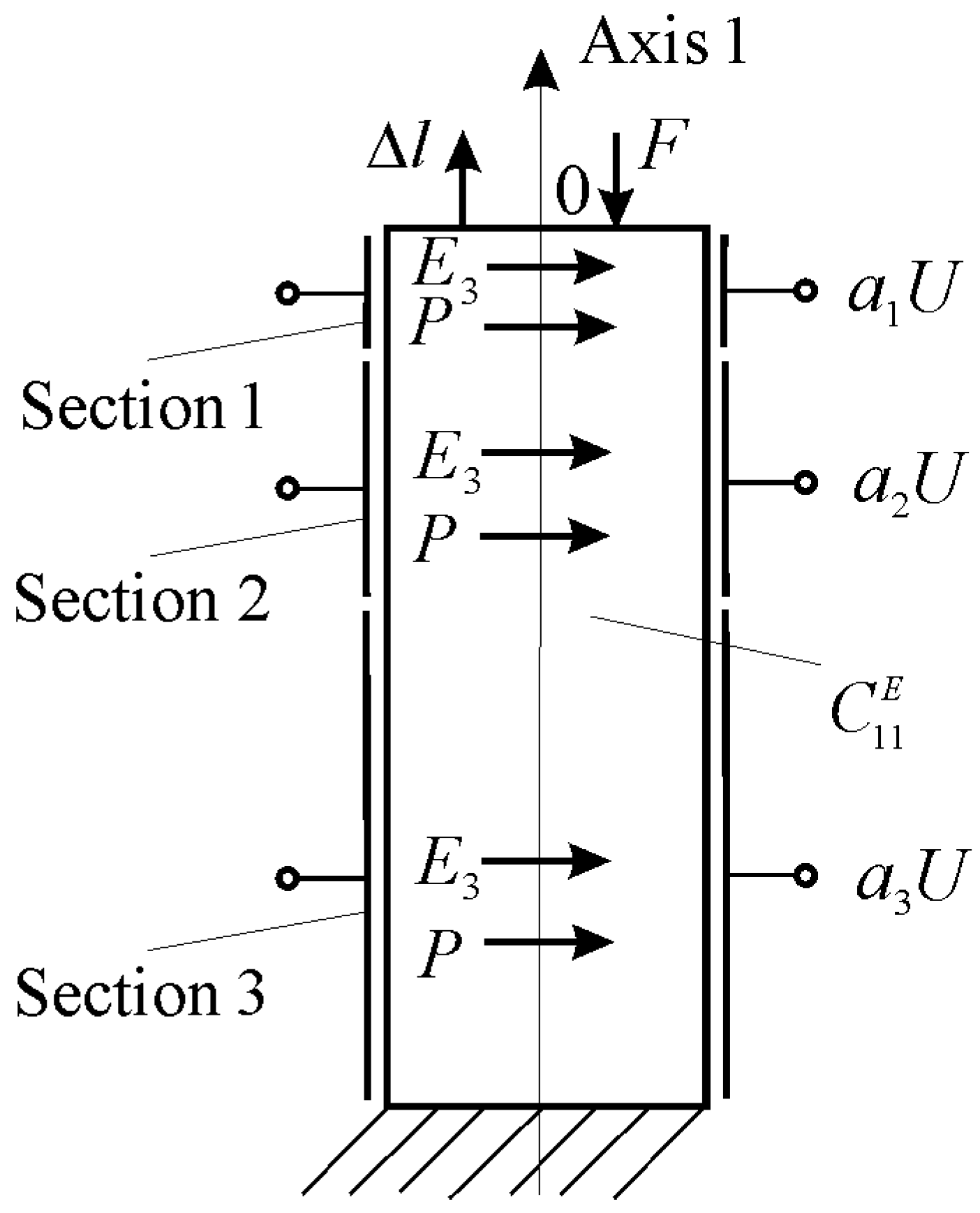
For a sectional piezoelectric engine at the transverse piezoeffect on Figure 1, the equation of the electroelasticity [6,7,8,9,10,11,12,13,14,15] has the form
where , , , , and are the relative deformation along axis 1, the transverse piezomodule, the electric field strength along axis 3 on Figure 1, the elastic compliance with and the mechanical tension along axis 1, respectively.

Figure 1.
Sectional transverse piezoelectric engine for nanomechatronics systems.
The displacement of the first section, a sectional piezoelectric engine at the transverse piezoeffect, has the form
where is the length of the first section engine and is the thickness.
The displacement of the k section, a sectional piezoelectric engine at the transverse piezoeffect for from (5), has the form
The displacement of a sectional piezoelectric engine at the transverse piezoeffect on Figure 1 for from (6) is obtained in the form
where is the binary code for the k section engine and is the length of a sectional piezoelectric engine.
The mechanical characteristic of a sectional piezoelectric engine has the form
where and are the maximum displacement of a sectional piezoelectric engine at and the maximum force at , respectively.
The mechanical characteristic of a sectional piezoelectric engine at the transverse piezoeffect has the form
consequently
where is the rigidity of a sectional piezoelectric engine at the transverse piezoeffect and is the length of a sectional transverse piezoelectric engine.
The maximum displacement and the maximum force at the transverse piezoeffect from the mechanical characteristic (8) have the form
For a sectional transverse piezoelectric engine from ceramic PZT at = 0.2 nm/V, = 1, and = 100 V for = 1, = 0, = 0; = 1, = 1, = 0; and = 1, = 1, = 1, the maximum displacements of a sectional piezoelectric engine are obtained: = 20 nm; = 60 nm; and = 140 nm.
The adjustment characteristic of a sectional piezoelectric engine at the transverse piezoeffect and elastic load has the form
consequently
The displacement of the first section engine at the elastic load has the form
where and are the rigidity of the load and a sectional piezoelectric engine, respectively.
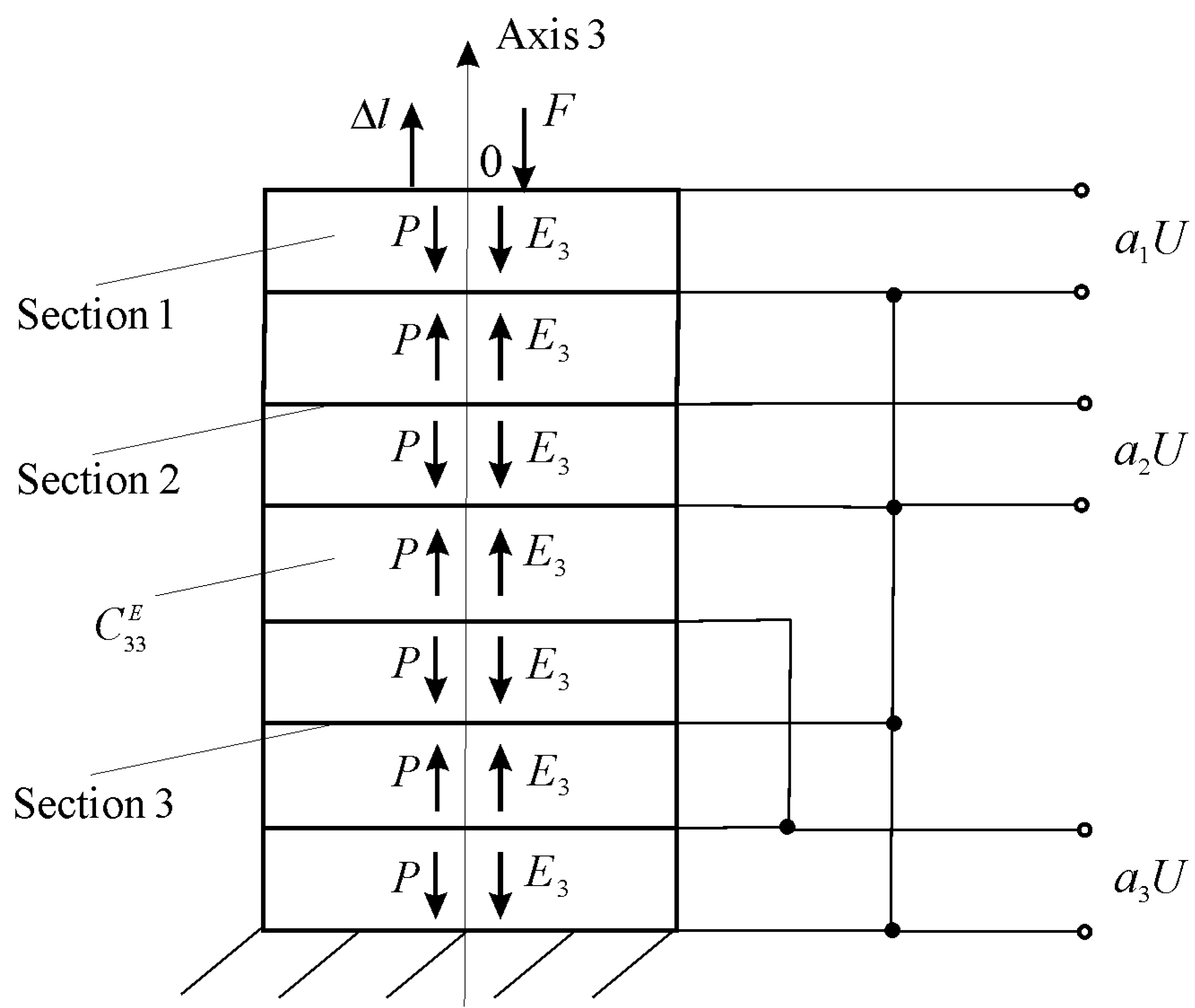
For a sectional piezoelectric engine at the longitudinal piezoeffect, the equation of the electroelasticity [6,7,8,9,10,11,12,13,14,15,28] has the form
where , , , and are the relative deformation along axis 3, the longitudinal piezomodule, the electric field strength along axis 3 on Figure 2, the elastic compliance with and the mechanical tension along axis 3, respectively.
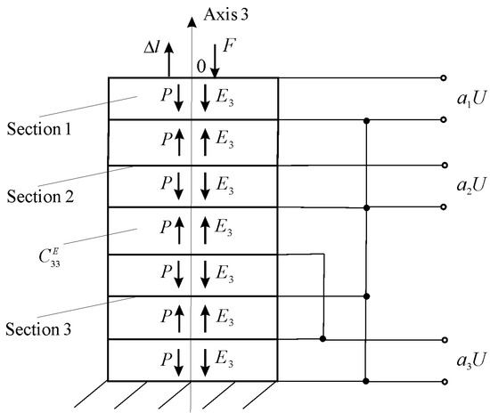
Figure 2.
Sectional longitudinal piezoelectric engine for nanomechatronics systems.
For the mechanical characteristic (8) of a sectional piezoelectric engine at the longitudinal piezoeffect, the maximum displacement and the maximum force are obtained in the form
where is the rigidity of a sectional piezoelectric engine at the longitudinal piezoeffect.
For a sectional longitudinal piezoelectric engine from ceramic PZT at = 0.4 nm/V, = 1, = 8 × 10⁸ N/m, and = 100 V for = 1, = 0, = 0; = 1, = 1, = 0; and = 1, = 1, = 1, the maximum displacements and the maximum forces of a sectional piezoelectric engine on Figure 3 are obtained (a) = 40 nm, = 32 N; (b) = 120 nm, = 96 N; and (c) = 280 nm, = 224 N.
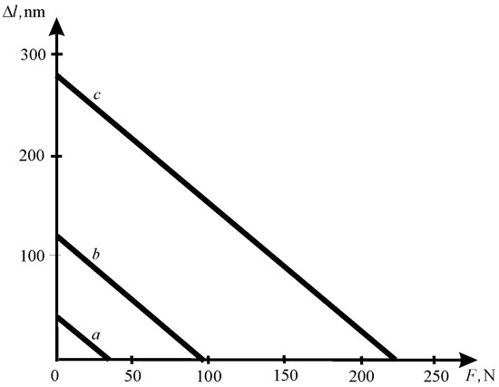
Figure 3.
Mechanical characteristic of sectional longitudinal piezoelectric engine.
The adjustment characteristic of a sectional piezoelectric engine at the longitudinal piezoeffect and elastic load has the form
consequently
where is the rigidity of a sectional piezoelectric engine at the longitudinal piezoeffect.
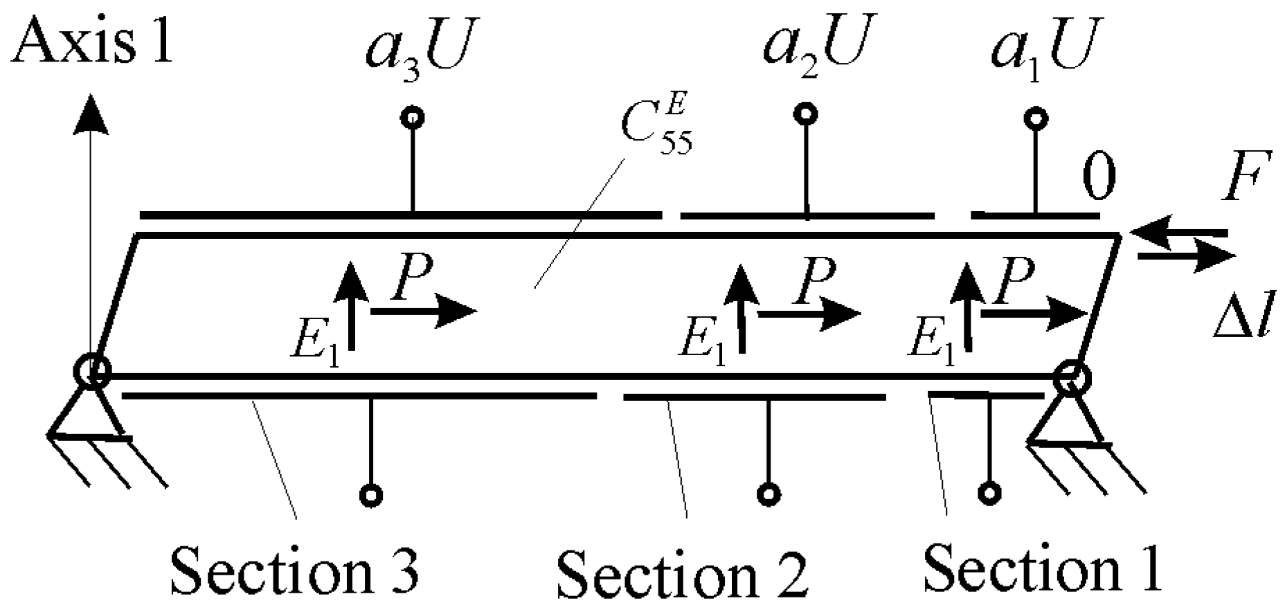
For a sectional piezoelectric engine at the shift piezoeffect, the equation of the electroelasticity [6,7,8,9,10,11,12,13,14,15] has the form
where , , , , and are the relative deformation along axis 5, the shift piezomodule, the electric field strength along axis 1 on Figure 4, the elastic compliance with and the mechanical shift tension along axis 5, respectively.
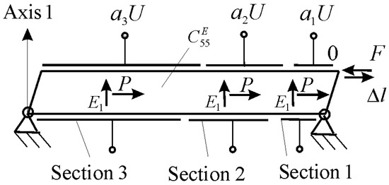
Figure 4.
Sectional shift piezoelectric engine for nanomechatronics systems.
The maximum displacement and the maximum force at the shift piezoeffect from the mechanical characteristic (8) have the form
where is the rigidity of a sectional piezoelectric engine at the shift piezoeffect.
For a sectional shift piezoelectric engine from ceramic PZT at = 0.5 nm/V, = 1, and = 100 V for = 1, = 0, = 0; = 1, = 1, =0; and = 1, = 1, = 1 the maximum displacements of a sectional piezoelectric engine are received: = 50 nm; = 150 nm; and = 350 nm.
The adjustment characteristic of a sectional piezoelectric engine at the shift piezoeffect and elastic load has the form
consequently
For the mechanical characteristic (8) of a sectional electroelastic engine, the maximum displacement and the maximum force are received in the form
where is the rigidity of a sectional electroelastic engine and is the length of a sectional electroelastic engine.
The adjustment characteristic of a sectional electroelastic engine with the N sections at elastic load is obtained in the form
consequently
where is the transfer coefficient on the voltage of a sectional electroelastic engine, is the deformation of the first section engine and c is the decimal code. In the work, the mechanical and adjustment characteristics of a sectional electroelastic engine are obtained.
3. Transient Characteristic of a Sectional Electroelastic Engine at Elastic–Inertial Load
Let us consider the dynamic characteristics of a sectional electroelastic engine for nanomechatronics systems. The transfer function of an electroelastic engine is determined under elastic–inertial load. The ordinary linear differential equation second order of an electroelastic engine [8,9,10,19,20,21,22,23,24,25,26,27] has the form
where , , , , , and are the Laplace transform of the displacement of an electroelastic engine, the coordinate, the Laplace operator, the wave propagation coefficient, the speed of sound at and the attenuation coefficient, respectively. The solution to this differential equation has the form
where , are the coefficients.
The coefficients are determined from the boundary conditions
The coefficients and have the form
The solution to the ordinary differential equation for an electroelastic engine has the form
With one fixed face of an electroelastic engine at , the equation of the displacement has the form
consequently
From the equation of the electroelasticity (1) for elastic–inertial load of an electroelastic engine the Laplace transform of the relative deformation at has the following form
where , are the mass and the rigidity of the load, respectively, whence
Therefore, the transfer function on the electric field strength of an electroelastic engine has the form
consequently
where is the rigidity of an electroelastic engine.
The transfer function on voltage of an electroelastic engine has the form
At elastic–inertial load for —where and are the masses of the load and the engine, respectively, with the approximation of the hyperbolic cotangent by two terms of the power series—the transfer function on the voltage for the lumped parameters of an electroelastic engine has the form
where is the time constant and is the coefficient attenuation for an electroelastic engine.
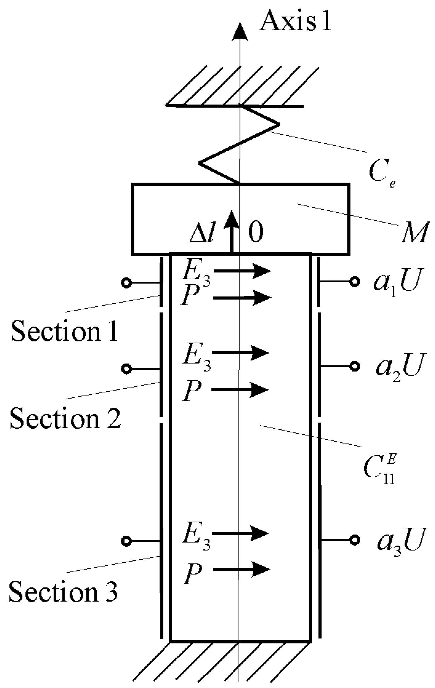
Therefore, the transfer function on the voltage for the lumped parameters of a sectional electroelastic engine at elastic–inertial load for on Figure 5 for nanomechatronics systems has the form
where and are the masses of the load and the sectional electroelastic engine, respectively; and are the Laplace transforms of the displacement and the voltage, respectively; and , , and are the transfer coefficient on the voltage, the time constant and the coefficient attenuation for a sectional electroelastic engine, respectively.
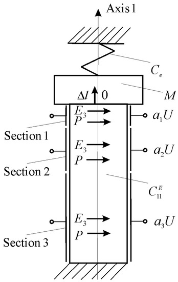
Figure 5.
Sectional transverse piezoelectric engine at elastic–inertial load.
The transient characteristic for the displacement of a sectional electroelastic engine at elastic–inertial load for nanomechatronics systems from (51) is obtained in the form
where , , , and are the time, the amplitude displacement, the amplitude voltage, the natural oscillation frequency, and the initial phase of oscillation, respectively. At = 1.1 nm/V, = 100 V, = 4 kg, = 2 × 10⁷ N/m, and = 0.5 × 10⁷ N/m for a sectional transverse piezoelectric engine from ceramic PZT, = 110 nm and = 0.4 × 10⁻³ s are obtained. The theoretical and practical parameters of a sectional piezoelectric engine are coincidences with an error of 10%.
Therefore, the transfer function and the transient characteristic of a sectional electroelastic engine at elastic–inertial load are received for nanomechatronics systems.
4. Results and Discussion
In this work, the static and dynamic characteristics of a multilayer sectional electroelastic engine for nanomechatronics systems are obtained. The transfer function of a sectional electroelastic engine is determined under elastic–inertial load.
In space equipments including the Space Interferometer Mission are increasingly seeking to use a multilayer piezoelectric stack engines for precision positioning to accuracies of the order of fractions of a nanometer. The effective piezoelectric constant is determined by summing the displacement for each element of the stack and is found in the form
where n is the number layers of a multilayer piezoelectric stack engine and is the longitudinal piezomodule. Therefore, a low voltage of about 60 V is used to control a multilayer piezoelectric stack engine for driving these precision mechanisms. For control, layers can be combined into sections [6].
Multilayer structures have been introduced in the piezoelectric engine because of the following advantages: much lower engine voltage, making them safer to use, and miniaturization of engine for nanomechatronics systems. The piezolayers of multilayer structure can be combined into sections. Splitting into sections allows to use sections independently in the piezoelectric engine. The voltage of about 100 V is applied to a piezolayer [7]. A multilayer sectional piezoelectric engine solves tasks of precise nanopositioning adjustment for nanomechatronics systems in nanotechnology [7,29].
In this study, we obtained a generalized mechanical and adjustment characteristics of a multilayer sectional electroelastic engine for nanomechatronics systems using the equations of the electroelasticity and the mechanical load. For the transverse, longitudinal, and shift piezoeffects, the mechanical and adjustment characteristics of a sectional electroelastic engine are obtained. In nanomechatronics systems, a sectional electroelastic engine is used for coded control as a digital-to-analog converter. The transfer function and the transient characteristic of a sectional electroelastic engine at elastic–inertial load are received for nanotechnology equipment.
5. Conclusions
The mechanical and adjustment characteristics of a sectional electroelastic engine for nanomechatronics systems are determined in this study. A sectional electroelastic engine is used as a digital-to-analog converter-engine for nanodisplacement. The dynamic characteristics of a sectional electroelastic engine at elastic–inertial load are obtained. The transfer function and the transfer coefficient of a sectional electroelastic engine at elastic–inertial load for nanomechatronics systems are determined.
For the transverse, longitudinal, and shift piezoeffects, the mechanical and adjustment characteristics of a sectional electroelastic engine are received for precise nanopositioning adjustment in nanotechnology, adaptive optics, and antennas. The expression of the transient characteristic for the displacement of a sectional electroelastic engine at elastic–inertial load is obtained for nanomechatronics systems.
Funding
This research received no external funding.
Institutional Review Board Statement
Not applicable.
Informed Consent Statement
Not applicable.
Data Availability Statement
Not applicable.
Conflicts of Interest
The authors declare no conflict of interest.
References
- Schultz, J.; Ueda, J.; Asada, H. Cellular Actuators; Butterworth-Heinemann Publisher: Oxford, UK, 2017; p. 382. [Google Scholar]
- Afonin, S.M. Absolute stability conditions for a system controlling the deformation of an elecromagnetoelastic transduser. Dokl. Math. 2006, 74, 943–948. [Google Scholar] [CrossRef]
- Zhou, S.; Yao, Z. Design and optimization of a modal-independent linear ultrasonic motor. IEEE Trans. Ultrason. Ferroelectr. Freq. Control 2014, 61, 535–546. [Google Scholar] [CrossRef] [PubMed]
- Uchino, K. Piezoelectric Actuator and Ultrasonic Motors; Kluwer Academic Publishers: Boston, MA, USA, 1997; p. 347. [Google Scholar]
- Ueda, J.; Secord, T.; Asada, H.H. Large effective-strain piezoelectric actuators using nested cellular architecture with exponential strain amplification mechanisms. IEEE/ASME Trans. Mechatron. 2010, 15, 770–782. [Google Scholar] [CrossRef]
- Sherrit, S.; Jones, C.; Aldrich, J.; Blodget, C.; Bao, X.; Badescu, M.; Bar-Cohen, Y. Multilayer piezoelectric stack actuator characterization. Proc. SPIE—Int. Soc. Opt. Eng. 2008, 6929, 692909. [Google Scholar] [CrossRef]
- Uchino, K. Multilayer technologies for piezoceramic materials. In Advanced Piezoelectric Materials: Science and Technology; Uchino, K., Ed.; Woodhead Publishing in Materials: Cambridge, UK, 2017; Chapter 11; pp. 423–451. [Google Scholar] [CrossRef]
- Afonin, S.M. Block diagrams of a multilayer piezoelectric motor for nano- and microdisplacements based on the transverse piezoeffect. J. Comput. Syst. Sci. Int. 2015, 54, 424–439. [Google Scholar] [CrossRef]
- Afonin, S.M. Structural parametric model of a piezoelectric nanodisplacement transduser. Dokl. Phys. 2008, 53, 137–143. [Google Scholar] [CrossRef]
- Afonin, S.M. Solution of the wave equation for the control of an elecromagnetoelastic transduser. Dokl. Math. 2006, 73, 307–313. [Google Scholar] [CrossRef]
- Cady, W.G. Piezoelectricity: An Introduction to the Theory and Applications of Electromechancial Phenomena in Crystals; McGraw-Hill Book Company: New York, NY, USA; London, UK, 1946; p. 80. [Google Scholar]
- Mason, W.P. Methods and devices. In Physical Acoustics: Principles and Methods; Mason, W., Ed.; Academic Press: New York, NY, USA, 1964; Volume 1, Part A; p. 515. [Google Scholar]
- Zwillinger, D. Handbook of Differential Equations; Academic Press: Boston, MA, USA, 1989; p. 673. [Google Scholar]
- Afonin, S.M. Structural-parametric model and transfer functions of electroelastic actuator for nano- and microdisplacement. In Piezoelectrics and Nanomaterials: Fundamentals, Developments and Applications; Parinov, I.A., Ed.; Nova Science: New York, NY, USA, 2015; Chapter 9; pp. 225–242. [Google Scholar]
- Afonin, S.M. A structural-parametric model of electroelastic actuator for nano- and microdisplacement of mechatronic system. In Advances in Nanotechnology; Bartul, Z., Trenor, J., Eds.; Nova Science: New York, NY, USA, 2017; Volume 19, Chapter 8; pp. 259–284. [Google Scholar]
- Afonin, S.M. Nano- and micro-scale piezomotors. Russ. Eng. Res. 2012, 32, 519–522. [Google Scholar] [CrossRef]
- Afonin, S.M. Elastic compliances and mechanical and adjusting characteristics of composite piezoelectric transducers. Mech. Solids 2007, 42, 43–49. [Google Scholar] [CrossRef]
- Afonin, S.M. Static and dynamic characteristics of a multi-layer electroelastic solid. Mech. Solids 2009, 44, 935–950. [Google Scholar] [CrossRef]
- Afonin, S.M. Static and dynamic characteristics of multilayered electromagnetoelastic transducer of nano- and micrometric movements. J. Comput. Syst. Sci. Int. 2010, 49, 73–85. [Google Scholar] [CrossRef]
- Afonin, S.M. Structural-parametric model electromagnetoelastic actuator nanodisplacement for mechatronics. Int. J. Phys. 2017, 5, 9–15. [Google Scholar] [CrossRef]
- Afonin, S.M. Structural-parametric model multilayer electromagnetoelastic actuator for nanomechatronics. Int. J. Phys. 2019, 7, 50–57. [Google Scholar] [CrossRef] [Green Version]
- Afonin, S.M. Structural-parametric model of electromagnetoelastic actuator for nanomechanics. Actuators 2018, 7, 6. [Google Scholar] [CrossRef] [Green Version]
- Afonin, S.M. Structural-parametric model and diagram of a multilayer electromagnetoelastic actuator for nanomechanics. Actuators 2019, 8, 52. [Google Scholar] [CrossRef] [Green Version]
- Afonin, S.M. A block diagram of electromagnetoelastic actuator nanodisplacement for communications systems. Trans. Netw. Commun. 2018, 6, 1–9. [Google Scholar] [CrossRef]
- Afonin, S.M. Decision matrix equation and block diagram of multilayer electromagnetoelastic actuator micro and nanodisplacement for communications systems. Trans. Netw. Commun. 2019, 7, 11–21. [Google Scholar] [CrossRef]
- Afonin, S.M. Condition absolute stability control system of electromagnetoelastic actuator for communication equipment. Trans. Netw. Commun. 2020, 8, 8–15. [Google Scholar] [CrossRef]
- Afonin, S.M. A Block diagram of electromagnetoelastic actuator for control systems in nanoscience and nanotechnology. Trans. Mach. Learn. Artif. Intell. 2020, 8, 23–33. [Google Scholar] [CrossRef]
- Afonin, S.M. Optimal control of a multilayer electroelastic engine with a longitudinal piezoeffect for nanomechatronics systems. Appl. Syst. Innov. 2020, 3, 53. [Google Scholar] [CrossRef]
- Bhushan, B. Springer Handbook of Nanotechnology; Springer: Berlin, Germany; New York, NY, USA, 2004; p. 1222. [Google Scholar]

Publisher’s Note: MDPI stays neutral with regard to jurisdictional claims in published maps and institutional affiliations. |
© 2021 by the author. Licensee MDPI, Basel, Switzerland. This article is an open access article distributed under the terms and conditions of the Creative Commons Attribution (CC BY) license (https://creativecommons.org/licenses/by/4.0/).