1. Introduction
Offshore structures such as pipelines, risers, and umbilicals require regular inspection and monitoring to assess their integrity, which will lead to improvements in safety and environmental protection and potentially increase their operational lifetime. With health and safety requirements becoming more stringent, the regular inspection of structures is becoming an essential element as part of preventive maintenance (PM). Offshore structures have to withstand harsh operating environments: cyclic wave loading, wind loading, corrosion, accidental damage, and marine growth [
1]. Damage occurring during installation, in service, and due to aging can pose significant hazards to people, assets, and the environment. To prevent catastrophic failures, these structures must be inspected, repaired, and, if necessary, removed on a periodic basis. Inspection or repair in the said environment is not easy and is associated with high safety requirements. These processes are usually carried out by trained divers, or the equipment for inspection or repair is deployed using remotely operated vehicles (ROVs). The procedures to be carried out by human divers are associated with human safety and limited to certain depths under water. The use of ROVs is very expensive and suffers from stability problems in the operating environment. Hence, robotic and automated systems are being investigated for deployment and for carrying out the required tasks under these extreme conditions for diagnostics of structural faults.
Depending on the type of structure and needs of the inspection method adopted, various robotic systems have been developed that vary in terms of complexity and method of deployment. A brief review on robotic systems for inspection was provided in [
2] and in frameworks for in-process robotic inspection systems [
3,
4]. The design and development of a robotic automated system for such an extreme environment requires the consideration of various factors such as materials, minimum human intervention, weight, ruggedized structure and enclosures, reliability, umbilical size, and safety. There is vast literature on the development of distributed control systems and on utilizing communication technologies to provide control methods—[
5,
6,
7,
8], to mention a few. However, due to the very nature of the operational environment, the use of hydraulic systems that are controlled remotely has been a norm in the subsea industry, and the use of electric drive and control systems using fieldbus technology in subsea applications is relatively recent.
As outlined by Rokne [
9], the transition from hydraulic to electric actuators and control systems in subsea applications is important in cases where high precision and tight dynamic control over the actuators are required. The importance of fieldbus technology is also emphasized for “control in the field” to have superior control for benefits of higher throughput and Health and Safety Executive (HSE) benefits in offshore, high-risk environments [
10]. This is also an essential step forward in developing autonomous systems in harsh environments.
With the identification of digitalization and improved controllability, detailed studies were carried out on various fieldbus systems in order to develop standard communication and protocol systems for subsea equipment by Subsea Instrumentation Interface Standardisation (SIIS), and Controlled Area Network (CAN) was identified as one of the most robust in terms of fault tolerance with multidrop systems [
11]. A further case study was carried out [
12] for oil and gas applications to apply CAN Open protocols with sensing systems in subsea equipment, which showed similar results to [
11] with regard to the limitations of the network when applied to a subsea environment as compared to land-based systems. The work presented here is application focused towards actuator control with fieldbus technology for the inspection of subsea structures in harsh environments. The work in this paper is a contribution towards fully enclosed actuators with on-board local control units including feedback and communication to the main controller. This was developed with consideration for the operating environment and, at the same time, maintaining an overall simple configuration as compared to hydraulic or electro-hydraulic systems which are controlled remotely from the topside and have limited dynamic control capabilities.
The present work describes the topology adopted for developing a distributed control system configured using a combination of fieldbuses to automate the inspection of underwater structures. With this hardware, it is possible to power and control the actuators underwater using a simple umbilical cable consisting of only a power line and a twisted pair for communication signals. This has the advantage of easing cable management and greatly reduces the drag for underwater operations at greater depths. For underwater units, the CAN bus interface was chosen as it is more robust and fault tolerant as compared to other fieldbus networks, as suggested in [
11] and [
12]. For the topside units, a combination of RS 485- and CAN-based communication was used considering the wide range of actuator and sensor availability for land-based systems.
Section 2 describes the main requirements for the system developed and an overview of the robotic structure and the overall system structure and components.
Section 3 details the control system hardware which is based on a fieldbus to implement distributed control and also details the design of the subsea actuators to keep the underwater units and the wiring to a minimum.
Section 4 provides an overview of the testing of the system in shallow waters at an underwater testing facility to prove the core functionality of the system. Conclusions of the work carried out here are summarized in
Section 5.
2. Robotic System
The design of a robotic system depends on the type of structure to be examined, inspection method, payload, other control mechanisms required to use the inspection device (e.g., fixed or scanning type), and environmental loads.
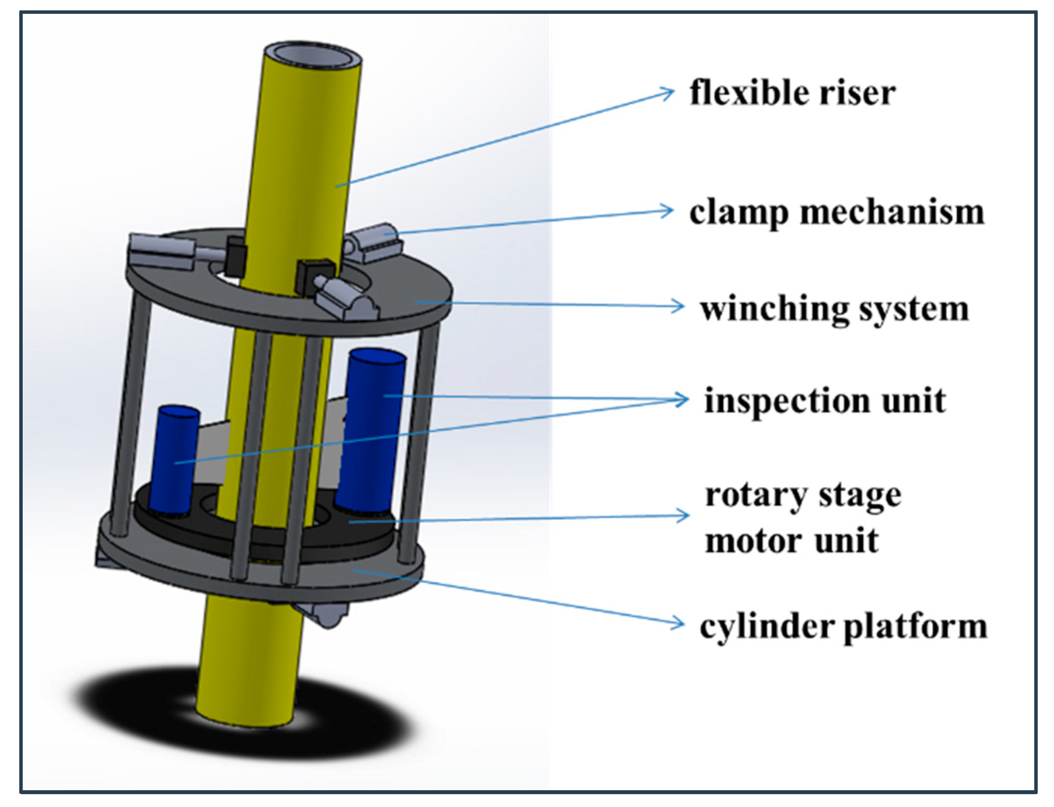
Figure 1 shows a 3-d model of such a system for the inspection of risers or pipelines. It includes a rotary scanning mechanism as the inspection device requires full 360-degree access to the structure.
To provide stability during scanning, a gripping mechanism was developed using a combination of linear actuators that grasp the structure during scanning. Other sensing devices included in the design are the vision camera and robot positioning sensor. To deploy and monitor the robotic system, the topside unit includes the deployment mechanism; sensors to monitor system parameters such as temperature, humidity, and gas detection; and a power supply.
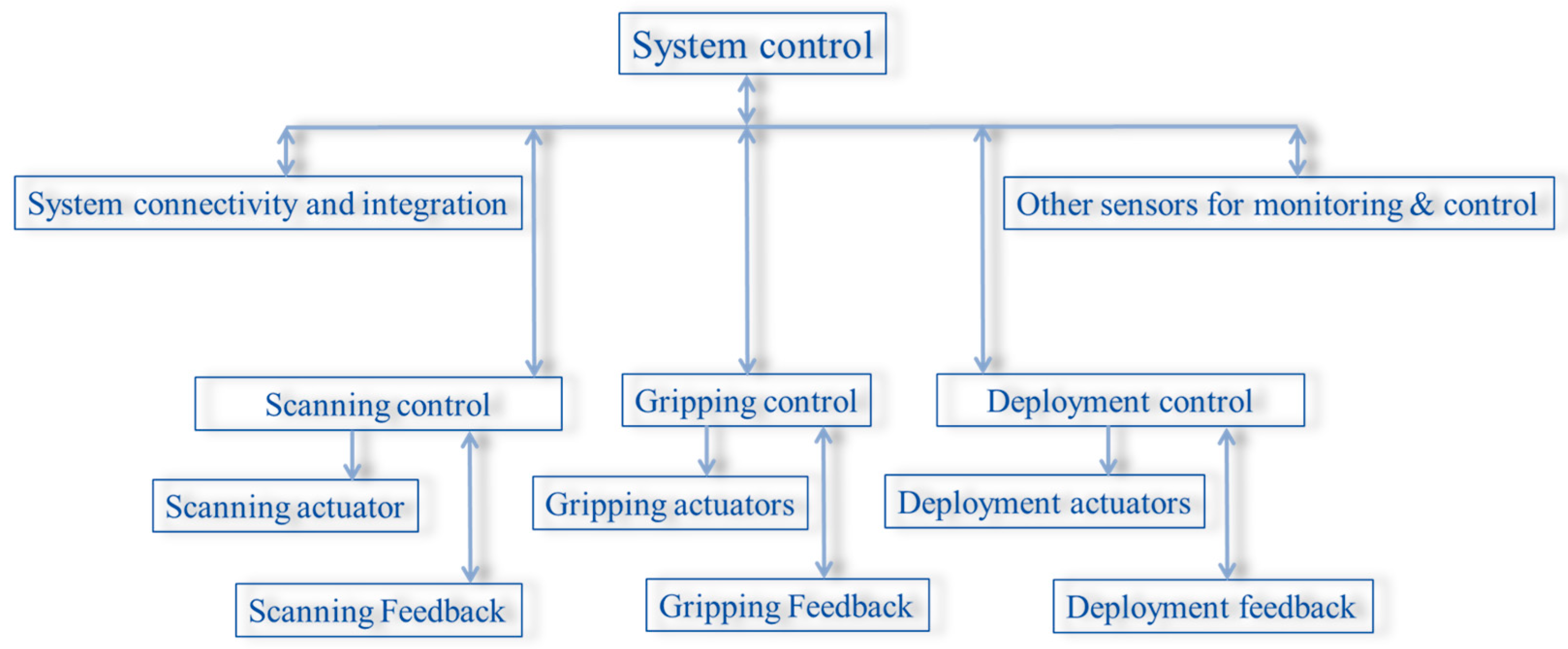
Figure 2 shows the system configuration involving various components of the system. The system consists of multiple actuators and sensors which are located at different places. The connectivity among these and the real-time monitoring and control of each are especially important.
Various design configurations for controlling the system are possible. There could be a powerful centralized controller that can access all the devices, implement the control algorithms, and drive the actuation systems as required. However, the distances involved in the positioning of subunits can introduce latencies in the implementation of real-time control of the actuators and also need a large number of wiring connections between all devices and the centralized controller. With advancements in the communication technologies and the design of integrated devices, there has been a shift from centralized to distributed control, and this concept has been used to address the above issues. The distributed control system configuration used was a combination of fieldbuses considering the performance and safety requirements and associated costs to achieve the required functionality of the system in real time.
3. Control Hardware Architecture Using Fieldbus
The development of fieldbus technology has facilitated the replacement of point-to-point communication and driven the development of efficient distributed systems. This is because it has simplified the hardware connectivity between devices and equipment. The aim of introducing fieldbus technology was to provide an industry standard for establishing communication among devices for easier configurability and interoperability from different vendors. However, a number of fieldbus standards have been established over time, and for industrial process fieldbus applications alone, ten different buses have been accepted by the International Electrotechnical Commission (IEC), starting with a basic analog 4–20 mA bus through to digital buses, i.e., profibus, interbus, Modbus, Controlled Area Network (CAN), devicenet, and Ethernet, to name a few.
Among the wide range of bus standards there exist great differences and incompatibilities that restrict the interoperability of the devices [
13]. Hence, selection of the right fieldbus type and devices is very important for designing the control system hardware and highly depends on the application. Specific parameters of concern to the design include data rate, noise immunity, bus faults, allowable length of transmission, number of network nodes allowed, cost, ease of adding additional nodes, and reliability. The present design was carried out with a combination of CAN bus and RS-485. This choice was mainly based on the easy availability of the devices based on RS-485 and the in-built bus arbitration and safety features for the CAN bus. Both standards include differential signaling that provides noise immunity in the industrial environment.
RS-485 is a half-duplex multidrop bus. However, it is not a protocol. It defines the physical layer of the transmission, and only one device at a time can send a message [
14]. This implies that the data transmission protocol, addressing scheme, and data collision avoidance implementation have to be done at the protocol or application software level.
The CAN bus was originally developed for the automotive industry during the 1980s by the Bosch Company for monitoring and controlling [
15]. CAN not only provides that physical layer definition but also incorporates mechanisms for addressing, failure detection, packet formation, and bus arbitration. The network management component of the CAN software can be used for configuration of the communication device parameters. During running operation, it also monitors and analyzes the network to provide diagnostic information of the communication network that provides transmission failure detection and automatic repetition of message transmission.
3.1. Layered Structure of the Communication Bus
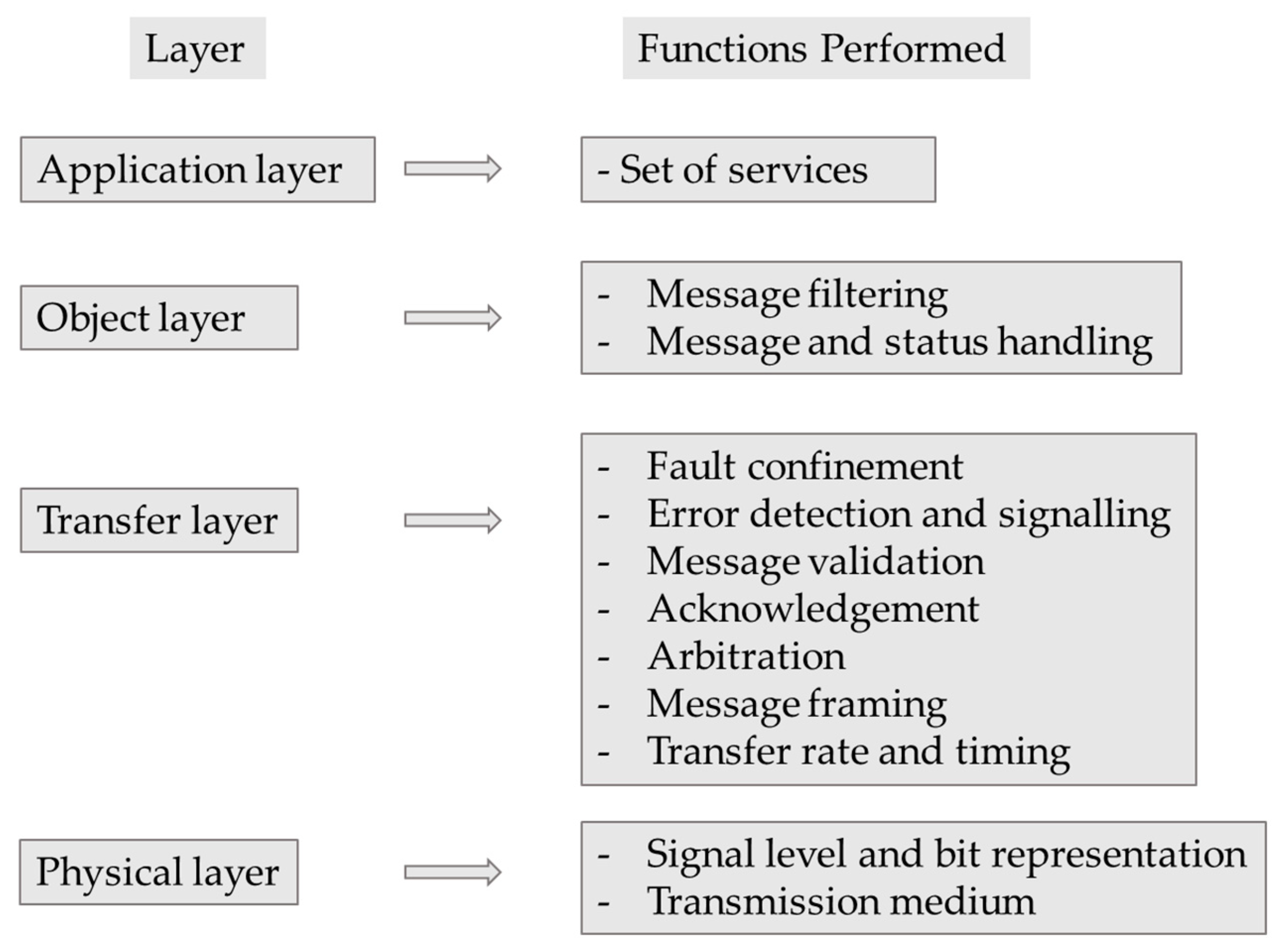
RS-485 in itself defines only the physical layer, and protocols are implemented in software that can be developed for a particular application. The CAN protocol defines the data link layer and part of the physical layer in the Open System Interconnection (OSI) model, as shown in
Figure 3.
The physical layer of the OSI model defines the medium and method of transmission. The data for CAN are usually transferred over a differentially driven pair of wires and are bit-synchronized. The signal is encoded in non-return-to-zero (NRZ) format.
The transfer layer represents the core of the protocol that defines the message forming. This layer contains the fault tolerance, error handling, and arbitration implementation of the protocol. The object layer carries out the message filtering based on the device ID and status and message handling.
3.2. Typical Signal Flow Configuration
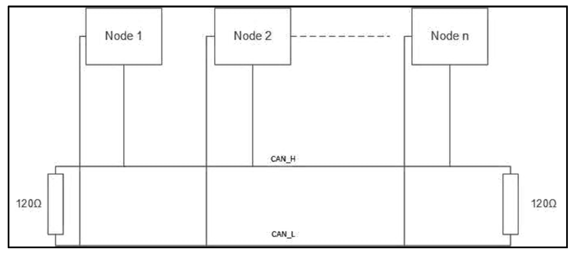
In the case of RS-485, the devices connected on the bus are identified by the device ID, and only one device can communicate at one time. In the CAN bus, the connected devices on the bus are the nodes and identified by node identifiers. It is also a half-duplex bus; however, multiple devices can send or receive the signals, and the transmission on the physical layer is taken care of by the node controllers. Hence, a node in a CAN network essentially consists of a CAN transceiver and CAN controller. A typical CAN bus signal flow configuration is shown in
Figure 4.
As shown, each device in the system is considered a separate node. As the CAN bus is a broadcast type of bus, i.e., all nodes can hear any transmission of data on the bus, each node is specified by its specific address, known as the node ID, to differentiate between the messages. When the communication packet is sent over the bus, it is sent either as a broadcast ID or specific node ID. The CAN controller of each device is configured with its ID and a local filter to respond to the messages only for that device. Similarly, when the message is transmitted to the remote controller, the controller identifies the device sending the message and processes the information accordingly.
As the CAN controller verifies the cyclic redundancy check (CRC) at the receiving end, which contains a 15-bit checksum for transmission error detection, the application software does not need to incorporate additional verification of the checksum at the application level. It receives only the valid packets of data, and the data with an invalid checksum are discarded.
3.3. Transmission Rate
The data rates that can be transmitted over a serial bus vary with distance. For RS-485, data bit rates up to 10 Mbps can be achieved, and for a CAN bus, 1 Mbps can be achieved. Each CAN bus packet can carry 8 data bytes. The total frame length for an 8 data byte packet is 111 bits. For a baud rate of 1 Mbps, the maximum speed achievable is 9009 frames/s. However, the bus speed decreases as the transmission distance increases due to delayed transmission and line capacitances. A conservative rule of thumb for bus lengths over 100 m is derived from the product of the baud rate in Mbps and the bus length in meters, which should be less than or equal to 50 [
16].
From the above, the baud rates achievable for different bus lengths are as in
Table 1.
3.4. Hardware Configuration
Due to the extreme operational environment, the design of such a system needs to consider various aspects such as reliable control, rugged enclosures for electronics, long-distance communication, and health and safety. The present robotic system consists of both underwater and topside control units. To realize the required functionality and suitability to operate in the said environment, the design of the robotic control hardware utilized the benefits of advanced technologies. For example, a standard electric motor that previously had no in-built monitoring features or real-time measurements can now have integrated driving and control electronics and a number of on-board measurements such as temperatures, flux, runtime errors, current draw, motor speed, and other useful data. In the system presented, a number of underwater motors were used to implement the gripper and scanning actuators.
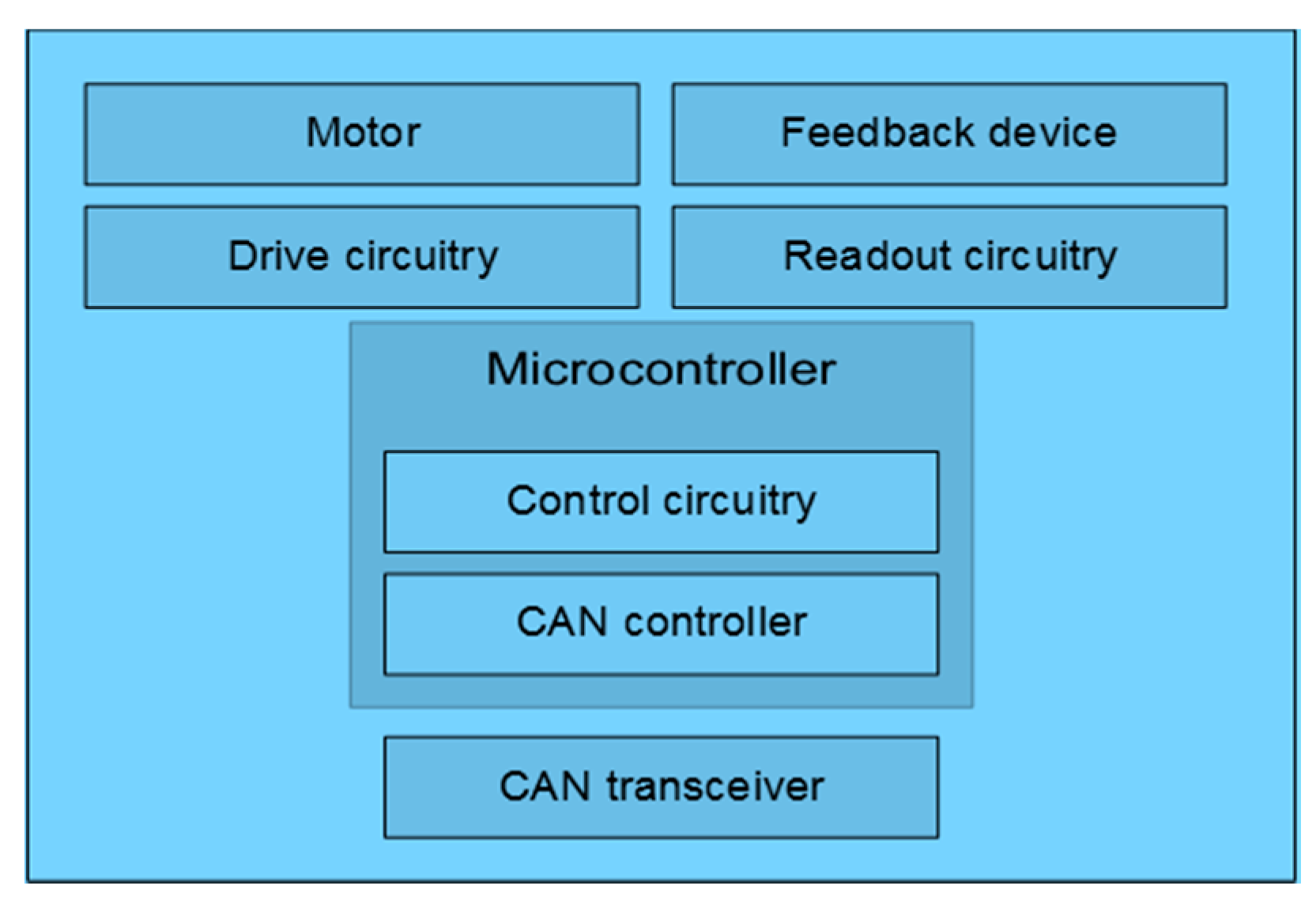
Due to higher manufacturing costs in developing underwater units, the control hardware was designed in such a way as to keep the number of underwater units and the interconnections to a minimum. The underwater units were connected to the topside controllers using an umbilical. As the length of the umbilical increases, not only do the size and weight increase but so does the drag force on the whole system from water currents. Hence, the other consideration in the design is to minimize the size of the umbilical; this was achieved by using a multidrop serial bus and using devices with equal power supply requirements. To ensure communication reliability and no congestion of data, the CAN bus is preferred over RS-485 for underwater units considering the criticality of system operation. Each actuator drive and control unit consisted of a motor, motor driver, feedback device, controller, CAN controller, and CAN transceiver, as shown in
Figure 5.
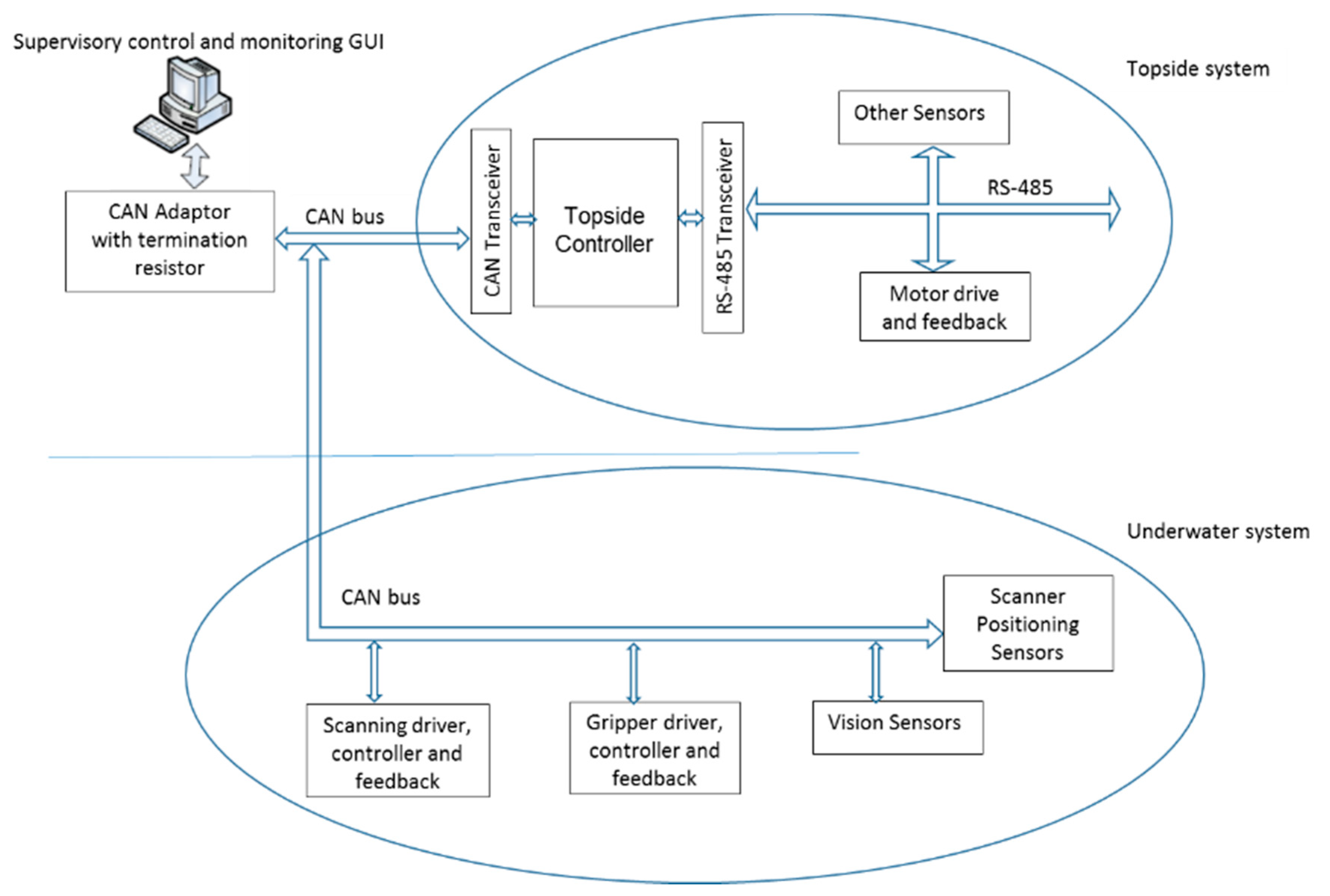
For the topside units, the individual control units’ connections were based on RS-485, which is a very common interface available on many devices. The topside units were controlled by an ARM-based microcontroller data acquisition board. This board was connected to the system supervisory controller using the same CAN bus as the underwater communication bus. The system hardware configuration is presented in
Figure 6.
Based on the data rates from
Table 1 and assuming a maximum cable length less than 200 m, a 0.25 Mbps baud rate was selected to allow a maximum speed of 2193 frames/s, which was adequate for the information required from the actuators to be passed on to the remote controller and vice versa.
The supervisory control software was implemented in Visual Studio to control the topside and underwater units. API functions for the CAN bus were used to monitor the CAN bus itself, for commanding individual units, and for getting feedback and updated status of the devices. Safety features were implemented in the control software to meet all industry standard requirements that are an essential element for the systems to be deployed in the subject environment. A system with limited capability was developed and underwent field trials to prove the core concept of the system. Based on successful trials, it is being implemented with enhanced capability in terms of automated control implementation to facilitate the system to work in different operational modes and with error handling.
4. Underwater Testing
The developed robotic scanner system was tested in a shallow subsea location for the inspection of a flexible riser. Prior to the seawater trials, the system was subjected to several laboratory-based trials to verify the functionality.
The robotic scanner system was managed from the control room on the surface through an umbilical link to power the subsea actuator units and the communication link, allowing the system to precisely control the scans at very low speeds required by the inspection system and allowing real-time monitoring and updates of system parameters.
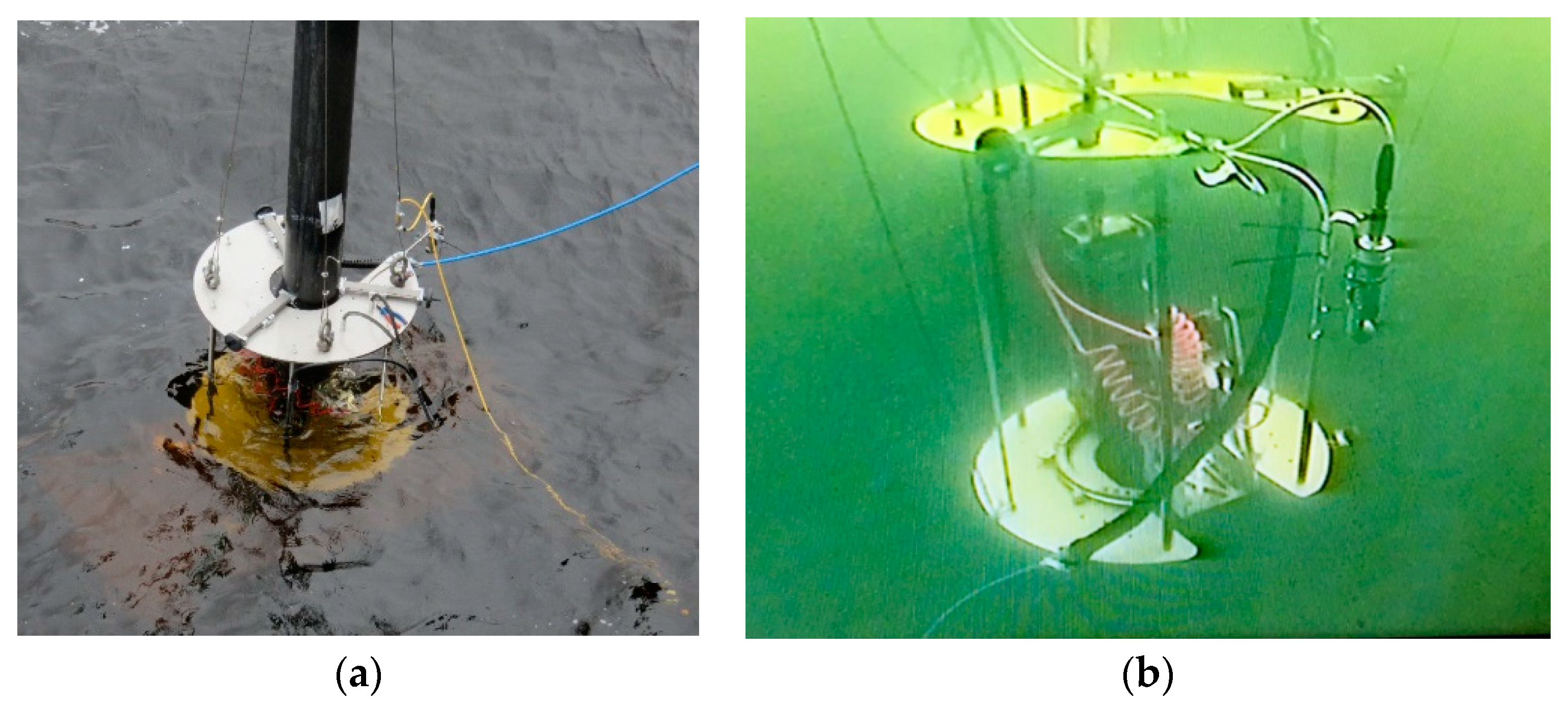
Figure 7 shows the snapshots from the underwater testing.
The core functionality of the system was proven during the sea trials. This included satisfactory results from the inspection system at precisely controlled scanning speeds ranging from 0.03 to 1 rpm as was required by the inspection system. The supervisory control system performed without failures in functionality or loss of data transmission at 200 Mbps. The system therefore proved its potential for enhanced capability in monitoring and control of the actuators. The parameters that were used in the tests to command, monitor, and update the system status are listed in
Table 2.
The parameters were significant for control of the actuator and for the user to monitor the health status and updates of the motion parameters during runtime. A set of improvements were recognized to make the system better for use in harsh environments, such as physical ruggedization by incorporating safety measures on power inputs, alarming indicators, and a hardened peli-case for the topside unit. This also included safety measures, system operational modes, and indication of the operational mode during runtime to be implemented in the supervisory control.


