1. Introduction
Mobile robot motion control problems have attracted considerable interest from researchers. The environments where the robot moves may vary from static or dynamic obstacles. In such an uncertain environment without prior information about the robot, target and obstacle, the basic aim is to safely move the robot without colliding with obstacles and reach the target point. The problem is the design of a safe and efficient algorithm that will guide robots to the target. The control system of these robots includes a set of algorithms. Recently, various methodologies have been utilized for mobile robot navigation [
1,
2,
3]. These are, artificial potential fields (APF) [
4,
5,
6], vision-based gaze guided control (GGC) [
7,
8,
9,
10,
11,
12,
13,
14,
15], fuzzy logic control [
12,
16,
17,
18], vector field histogram (VFH) [
19,
20], rapidly-exploring random trees [
21,
22], and obstacle avoidance and path planning [
23] algorithms. The fuzzy logic controller is one of the efficient techniques, which tends to be used actually for steering control in unpredictable environments [
3,
24,
25]. Fuzzy logic can smoothly be concerted to handle various types of linear and nonlinear systems like the human model perception process in uncertainty [
26]. Motion control of a mobile robot in an unstructured dynamic or static environment is usually characterized by a number of uncertainties that characterize real-world environments. To have exact and complete for prior knowledge of these environments is not possible. As the membership sets of the type-2 fuzzy systems are fuzzy, they offer a stronger solution to the type-1 fuzziness to represent and address uncertainty types. Type-1 fuzzy control cannot handle such kind of uncertainties. For this reason, the type-2 fuzzy system [
24,
27] is preferred to handle uncertainties and increase performance of the control navigation system that was introduced by Zadeh [
28,
29]. Type-2 fuzzy sets theory has been further developed by Mendel and Karnik [
24,
30,
31]. Theoretical background computational methods of IT2FIS and its design principles were developed for type reduction [
32,
33,
34,
35].
In the paper, a gaze guided robot control system, based on eye gaze using the type-2 fuzzy controller, is presented. It aimed to determine the robot’s direction based on the target location and create wheel speeds based on gaze direction and demonstrate how gaze could be used for automatic control of a mobile robot. That means to obtain a model of the robot moving towards the objects by looking directly at the object of interest in the real world. The interaction methods are expected to benefit users with mobility in their daily works. The intent of gaze direction amplitudes and the angle variables are applied for designing the motion control system’s input. The input variables are image coordinates in 2D image space of the scene monitored by the overhead camera. Eye movements identified such as looking up, down in
y (eye width) coordinates and left and right in
x (eye height) coordinates values were mapped to the mobile robot steering commands. The approximate width (X) and height (Y) of the eye was taken into account for the inputs. Gaze combination control is a benefit from effective hands-free input parameter of remote vehicles control. Gaze-based robot control work done in this regard is relatively scarce. Combining different types of technology with eye based systems [
36,
37,
38,
39,
40] integration can be useful for disabled, elderly and patients peoples that especially with neuro-motor disabilities. They can remotely control a moving platform [
11,
12,
41,
42] with these technologies in complex daily tasks [
14,
43]. A wheelchair is a good substitute, for example Reference [
44]. It’s orientation commands are created by a wheelchair mounted eye movement tracking system [
45,
46,
47].
The proposed gaze guided robot control (GGC) system consist of an EV3 robotic platform. It is highly customizable and provides advanced LabVIEW programming features [
48,
49]. In this platform, two high-resolution cameras are used. The first camera is mounted on the robot moving platform for transmitting a live video to the user screen. The second camera is used to identify the user’s eye movement and translate this gaze direction to the host system to calculate the robot’s steering control by using soft computing technique. The goal is to process to robot’s movements where the user is looking at the display screen. To make the robot move around in the vibrant environment under the visibility of an overhead camera, it is focused on the remote settings with a 2D gaze guided driving system such as forward, backward, left and right.
This paper is organized as follows.
Section 2 represents the procedure of the gaze guided system including a vision system of gaze tracking, the control system of the type-2 fuzzy mechanism and its application and experimental platform. The experimental design and results of the proposed methods are given in
Section 3.
Section 4 includes the discussion. Finally,
Section 5 concludes the paper and recommendation for future works.
2. Method of Gaze Guided System
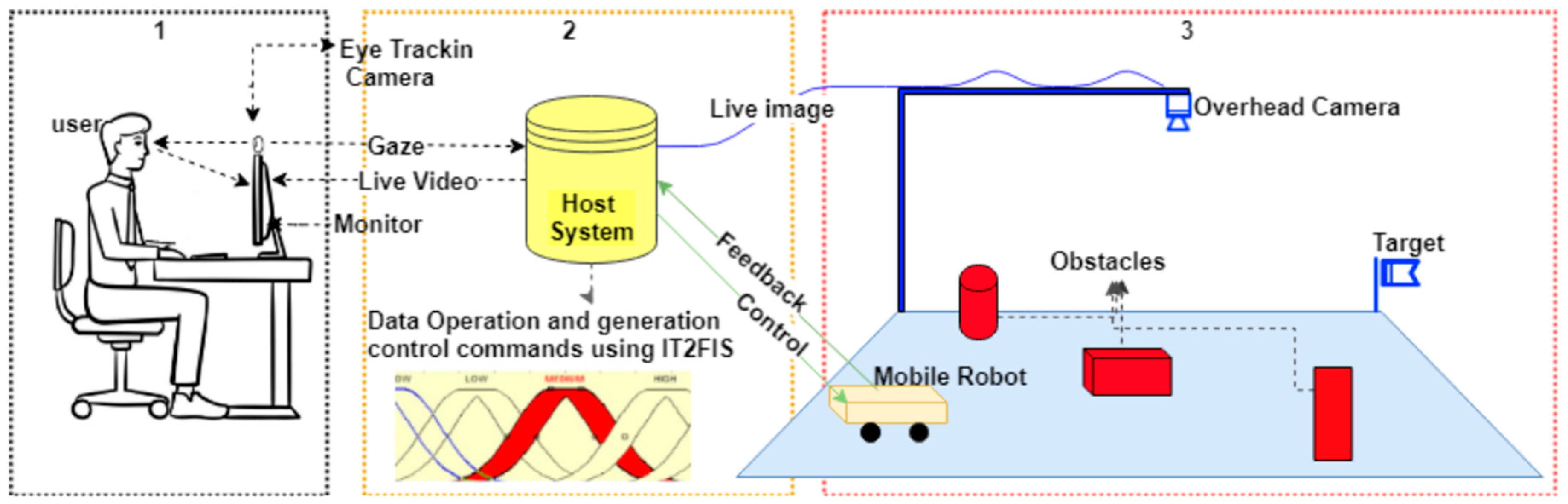
The intention of the system’s architecture is to achieve an influential integration of eye tracking technology with practical GGC system. The overall concept of gaze guided robot control system can be demonstrated in
Figure 1. In this structure, it is illustrated how different physical elements can be attached and communicate. The system architecture is divided into three parts. The first part is (user side) the user inferences, which are related to the eye tracking subsystem and the eye movement translation into robotic platform commands (1), the second part (host-IT2FIS) is data processing and command execution (2), the third part (robot side) is a robot moving environment under the visibility of an overhead camera. This framework includes four parts: an eye tracking system which can track user’s eyes, an overhead camera system that supplies the video feedback to the user, a wheeled mobile robot and the host computer system which is accountable for collecting the gaze data and commentate it into robot motion commands. The mobile robot used in this platform has an ARM9-based processor at 300 MHz Linux-based operating system. Detailed properties can be viewed in [
50]. A well-developed programming interface based LabVIEW programming language allows us to transmit movement information, depending on the direction of the gaze, to the robotic platform via Bluetooth. The image acquisition camera [
51] is able to provide live video with a resolution of 480 × 640 at 30 fps. The overhead camera height from the floor is approximation 2 m. The system software principally consists of two parts: the vision detection (eye tracking, robot tracking) and motion control algorithm. Sub-titles and details of the system are given below.
2.1. Eye-Gaze Tracking GGC System
The GGC control system architecture is shown in
Figure 1. In the first block (1), a user sitting in a chair and watches the live video from an overhead camera. The movement of the robot is monitored on this screen. Wherever the robot is required to move, the user looks at that side. The visual attention on that side is extracted from gaze data. To perform the robot navigation, the visual attention is converted from image space to 2D Cartesian space and produces control commands from this coordinate system. The point of gaze as the user observes the video frames is utilized for robot motion control inputs. The direction and speed are regulated by distance from the center point of the eye as seen in
Figure 2. X-axis regulates steering and y-axis regulates robot speed.
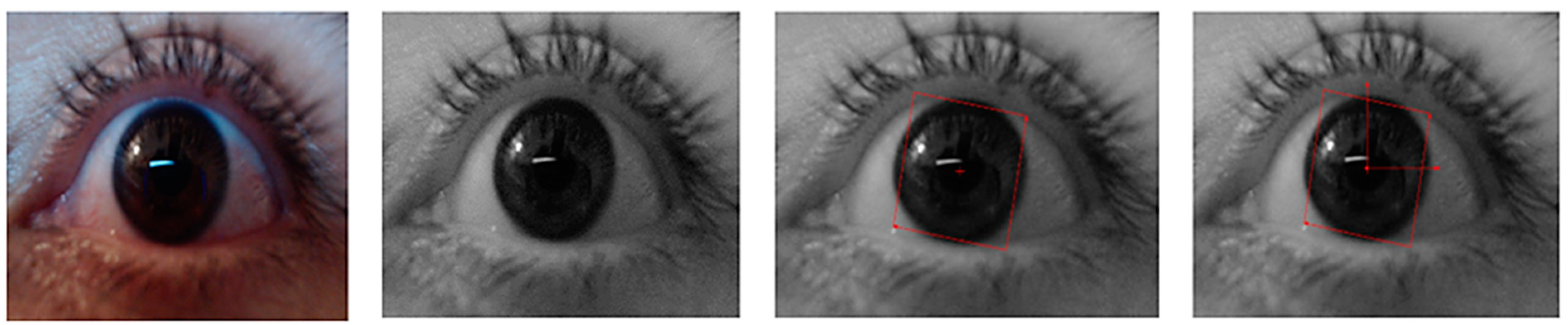
A high-resolution webcam [
51] is used to track eyes where the user is looking. It is a video-based remote eye tracking system. A shape adapted mean shift algorithm [
52] is utilized which is asymmetric and anisotropic kernels for object tracking which is process the image and calculates the point of gaze coordinates (see
Figure 3).
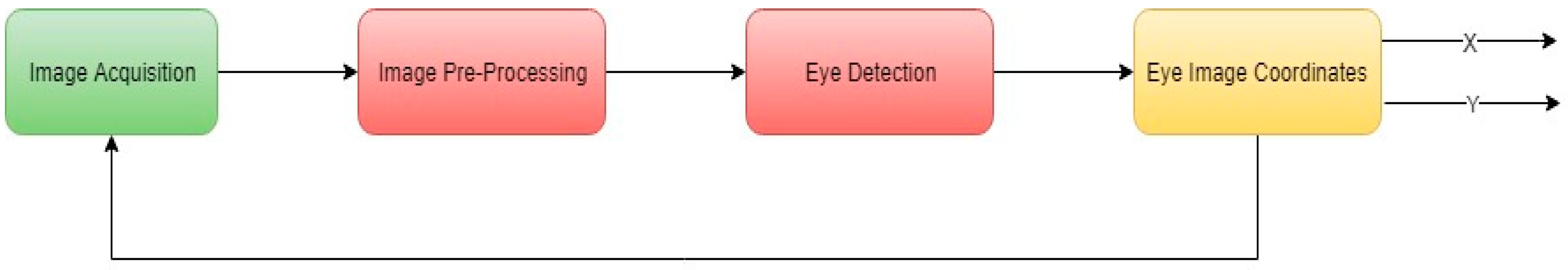
A series of raw image continuously capture in image acquisition step (see
Figure 4). The image tackled in this step is important in order to get the relevant Region of interest (ROI). The algorithms have been implemented using NI Vision Builder programming tools. The images are sent to the NI Vision system for machine vision and image processing applications. Image pre-processing makes easier to extract ROI. The analysis has purposed the removal of uninterested information to reduce the processing area. The original image is transformed into a grayscale and masked image that does not need to detect an eye feature point. A morphological operation has been applied for increasing the detection accuracy. A shape adapted mean shift algorithm has been applied which provides angular as well as a linear offset in object shapes.
This algorithm allows tracking eye templates with changing shapes and size and a built-in function using the NI vision assistant. The tracking template position is well-considered as the reference and its coordinates are taken into account. In the final image analysis, the eye coordinate system is obtained (see
Figure 5).
2.2. Overhead Camera System-Robot Tracking
In
Figure 1 (3. robot side), the graphical representation of an overhead camera based robot tracking field is shown. The environment where the robot moves is characterized by static obstacles. Gaze-based collision-free motion control of the robot in such a static environment is important. Environment model is captured by an overhead camera and sent to the NI vision system then the mobile robot on the field is tracked by a standardized vision system. The center of the moving robot area is accepted as (0,0). Horizontal (x) and vertical (y) axes represent the robot direction and wheel velocity. The information of the robot motion control environment is received by the host computer, and the robot tracking algorithm is executed. The robot’s position is continuously tracked and updated considering the acquired information from the sequentially captured images. Decision strategy is improved in the host system for plans the robot motion and corresponding velocity commands. The host computer regulates the rotational velocities of wheels and sends these commands to the robot. An experiment image shown in
Figure 6 has captured by the overhead camera and this image is sent to the NI vision system and user monitor.
The robot steering control command is produced by eye gaze movement as explained before. After defining the eye gaze coordinates, the output signal calculated for robot motor speeds by using type-2 fuzzy control sent via Bluetooth.
2.3. Interval Type2 Fuzzy Control System
The design and theoretical basis of a type-2 fuzzy model for mobile robot motion control has been presented in this section. This is planned to supply the basic thoughts needed to explain the algorithm using gaze input variables and rule base to determine the value of the output system. Fuzzy type-2 has been verified to be a powerful tool for controlling a complex system because of its robustness for controlling nonlinear systems with characteristic and uncertainties [
33,
53]. The concept of the type-2 fuzzy set was proposed by Zadeh [
28,
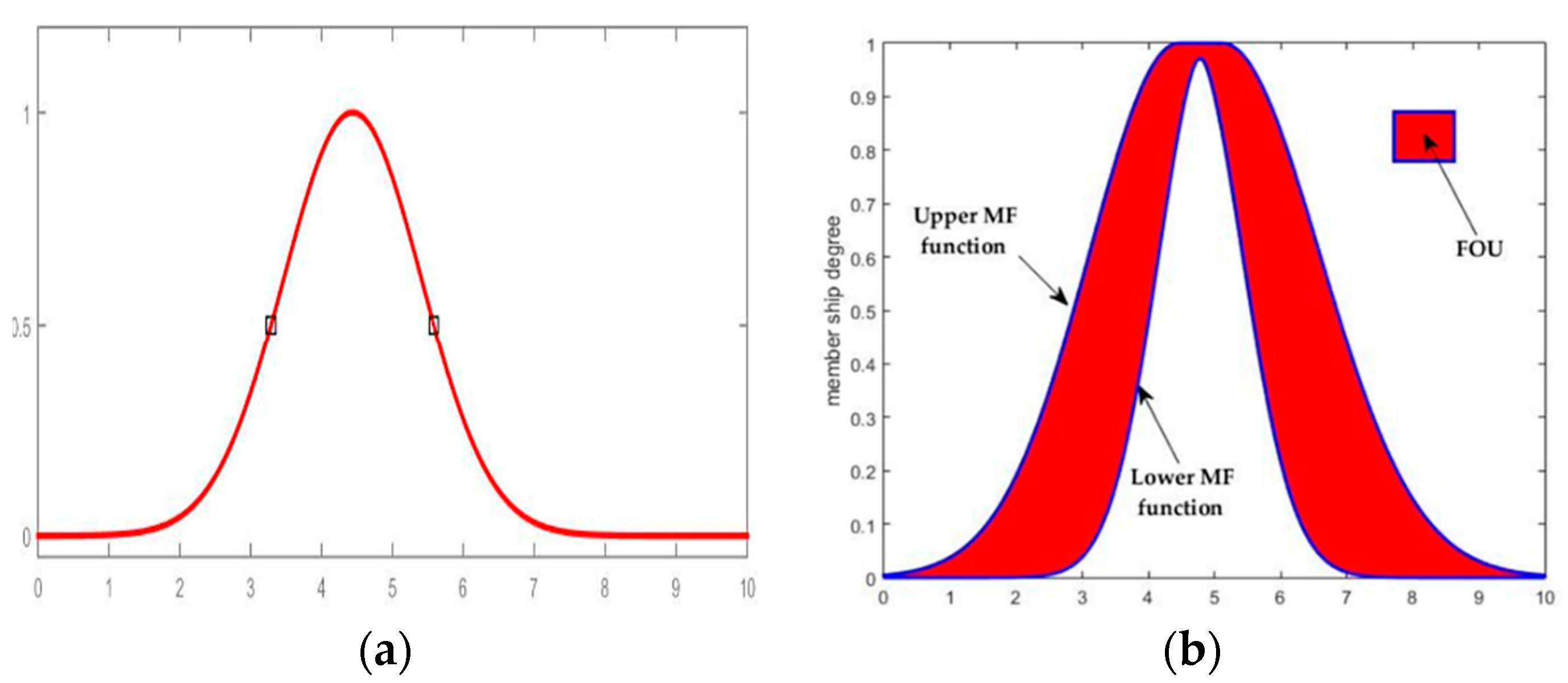
54] as an extension of type-1 fuzzy logic. It is able to model uncertainties in a much better way for control application. The appearance of uncertainties in nonlinear system control using the highest and lowest value of the parameter extending type-1 (
Figure 7a) fuzzy to type-2. (
Figure 7b). Uncertainty is a characteristic of information, which may be incomplete, inaccurate, undefined, and inconsistent and so on. These are represented by a region called a footprint of uncertainty (FOU) that is a limited region of upper and lower type-1 membership function.
An interval type-2 fuzzy set denoted by
, it is expressed in (1) or (2).
Hence,
,
it is considered as interval type-2 membership function as shown in
Figure 8.
where
donate the union of all acceptable
and
. An IT2FIS can be explained in terms of an upper membership function
and a lower membership function
.
is just the interval
,
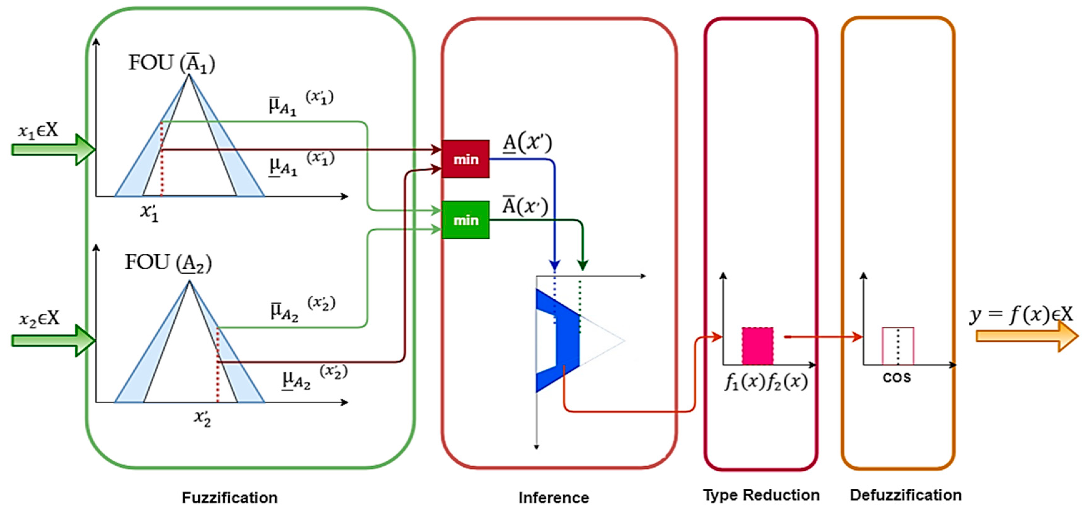
. A type-2 FIS is characterized by IF-THEN rules, where the antecedent and consequent sets are of type-2. The fundamental block used for designing the type-2 controller is the same as used with type-1. As shown in
Figure 8, A type-2 FLS includes a fuzzifier, a rule base, a fuzzy inference engine, and an output complement. The output processor includes a type-reducer and defuzzifier; it produces a type-1 fuzzy set output (from the type-reducer) or a crisp number (from the defuzzifier) [
53]. Type reducer is added because of its association with the nature of the membership grade of the elements [
35].
2.3.1. Fuzzifier
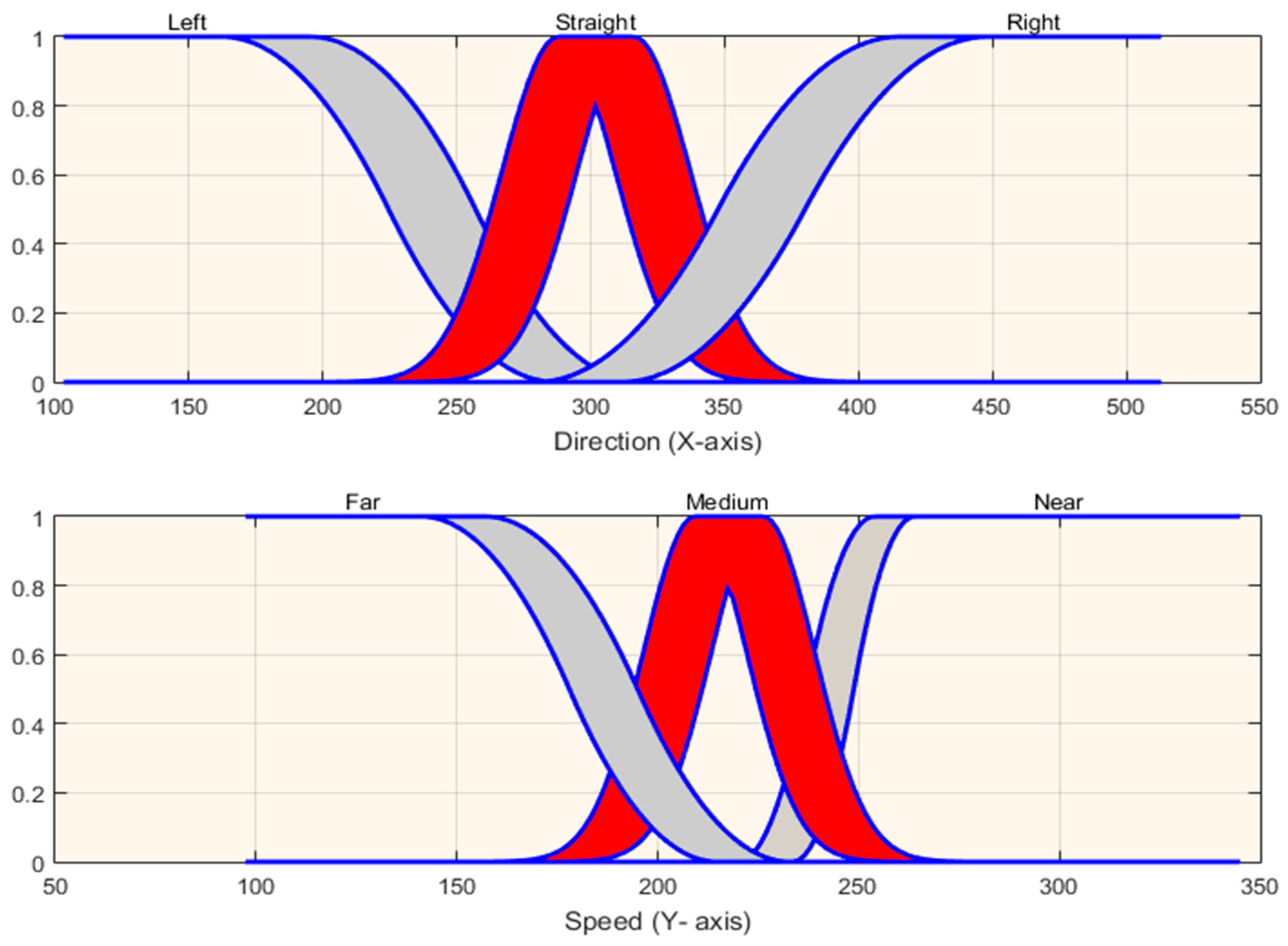
In this case, the inputs of the fuzzy sets are described. There are two inputs parameter used in the proposed system. These are named robot direction and robot speed respectively. The width (X) and height (Y) of the eye was taken into account for the input membership functions’ values range (see
Figure 9). As mentioned before, X-axis is representing the robot direction and Y-axis is representing the robot speed which is used to determine the two crisp inputs variables.
Table 1 shows the width and height information of the eye. These data are taken into account for the input function. In this table, it is illustrated that the eyes’ start and end coordinate space in 2D is used for arranging the membership function. The membership functions consist of one or several type-2 fuzzy sets. A numerical vector
of fuzzifier maps into a type-2 set
. Type-2 fuzzy singleton is considered. In a singleton fuzzification, the inputs are crisp values on nonzero membership. We contemplate three fuzzy membership functions for the robot direction with labels
,
,
. These are indicating left, straight, and right respectively as illustrated in
Figure 10. We worked using Gaussian and sigmoidal membership functions. A Gaussian type-2 fuzzy set is one in which the membership grade of every domain point is a Gaussian type-1 set contained in [0,1]. These functions are unable to specify asymmetric and archive smoothness membership function which are important in certain applications. The sigmoidal membership function, which is either open left, right asymmetric closed, it is appropriate for representing concepts such as very large” or very negative”. In the same method, we contemplate three membership functions for robot speed with labels
,
,
, these are indicating near, medium, far respectively as illustrated in
Figure 10. The variable range of functions is not infinite (see
Figure 10).
The output fuzzy controllers are the left and right velocities of the wheel speed. The linguistic variables are implemented with tree membership function. For both right and left wheel speed, these are labeled as
,
,
—slow, medium and fast respectively. It is illustrated in
Figure 11.
2.3.2. Fuzzy Inference Engine
The inference engine combines rules and gives an outline from input to output type-2 fuzzy sets.
Figure 8 shows a graphical representation of the relationship between input and output. It is necessary to compute the intersection and union of type-2 sets and implement compositions of type-2 relations. The desired behavior is defined by a set of linguistic rules. It is necessary to set the rules adequately for the desired result. For instance, a type-2 fuzzy logic with
p inputs (
) and one output
with
rules have the following form.
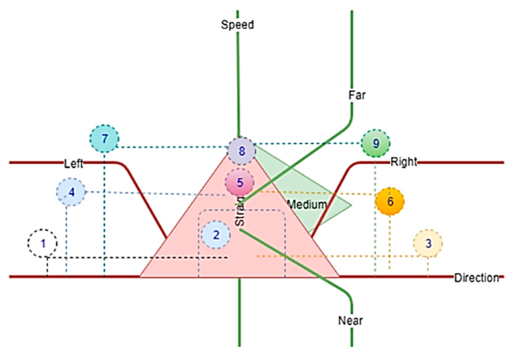
The knowledge bases related to the robot wheels speed are reported in
Table 2. The approximate locations of the rules formed in the knowledge base in the coordinate plane are shown in
Figure 12.
In this experiment, we used type-2 fuzzy sets and minimum t-norm operation. The rule firing strength
for crisp input vector is given by type-1 fuzzy set.
where
The graphical representation of the rules of the system is shown in
Figure 12. These are composed of input and output linguistic variables. Nine inference rules are designed to determine how the mobile robot should be steered and velocity. In each rule, a logic and operation is used to deduce the output. In
Table 2 we present the rule set whose format is established as follows:
Rule 1: IF Direction (X) is left and speed (Y) is medium, then left wheel speed (Lws) is small and right wheel speed is medium.
2.3.3. Type Reducer
Type reducer creates a type-1 fuzzy set output which is then transformed into a crisp output through the defuzzifier that combines the outputs sets to acquire a single output using one of the existing type reduction methods. Type reducer was proposed by Karnik and Mende [
32,
34,
55]. In our experiments, we used the center of sets (cos) type reduction method. The expression of this method can be written in the following Equation (6).
The consequent set of the interval type-2 determined by two endpoints (
). If the values of
and
which are associated with
are donated
and
, respectively, and the values of
and
which are associated with
are donated
and
respectively, these points are given in Equations (7) and (8).
where
and
are the output of IT2FIS, which can be used to verify data (training or testing) contained in the output of the fuzzy system.
2.3.4. Defuzzifier
The interval fuzzy set
variables obtained from type reducer are defuzzified and the average of
and
are used to defuzzify the output of an interval singleton type-2 fuzzy logic system. The equation is written as
3. Experiments and Results
In this paper, we focused on intelligent vision-based gaze guided robot control systems. The evaluation and validation of this method were tested with several experiments. The experiments were performed under an overhead camera image and using type-2 fuzzy control system. The aim is to make strategic planning and implement remote control of the robot on the base of gaze coordinates where user looking for. The experiments included two stages; evaluation and determination of gaze coordination and using this information as input command effectively for robot control. In our proposed method, we have designed an interface system where the user looks at the experimental field view from the overhead camera on the computer monitor. The eye gaze tracker is calibrated based on real-world eye viewing fields. The human eye view field is an essential factor in getting the coordination system. The closed eye situation is also identified by the computer program and is used to stop the robot. Then the gaze coordinates are utilized to control the robot remotely. It aims to directly control the robot after calibration of the gaze tracker. The robot direction and speed are modulated linearly by the distance from the center of the gaze coordinate. In the eye horizontal plane, the x-axis represents the movement of the eye gaze coordinate and the vertical plane coordinate system represents the mobile robot wheel speed input variables. In order to determine robot steering, this coordinate system is considered. Commands for robot motion control are extracted and updated for every 250 ms continuously.
The simulation results show the ability of the type-2 fuzzy logic controller to simultaneously determine human intention from the combined viewpoint and eye gaze. Nevertheless, the proposed method is powerful to determine robot speed, orientation, and obstacle avoidance. In
Figure 13, the simulation of the robot’s initial and goal points is illustrated and robot motion data on this behavior is also shown in
Table 3.
The outcomes of the experiment and simulation are illustrated graphically and plotted separately to elucidate the effect of gaze based on the fuzzy type-2 rule set in
Figure 14,
Figure 15,
Figure 16,
Figure 17,
Figure 18 and
Figure 19. In
Table 3, it can be seen that robot wheel speeds are change according to the gaze coordinates. In this table, there are only a few examples. The details of these data are shown graphically below in
Figure 15,
Figure 17, and
Figure 18. Various scenarios were performed to test the proposed method in a real environment. The experimental setup is shown in
Figure 14 and
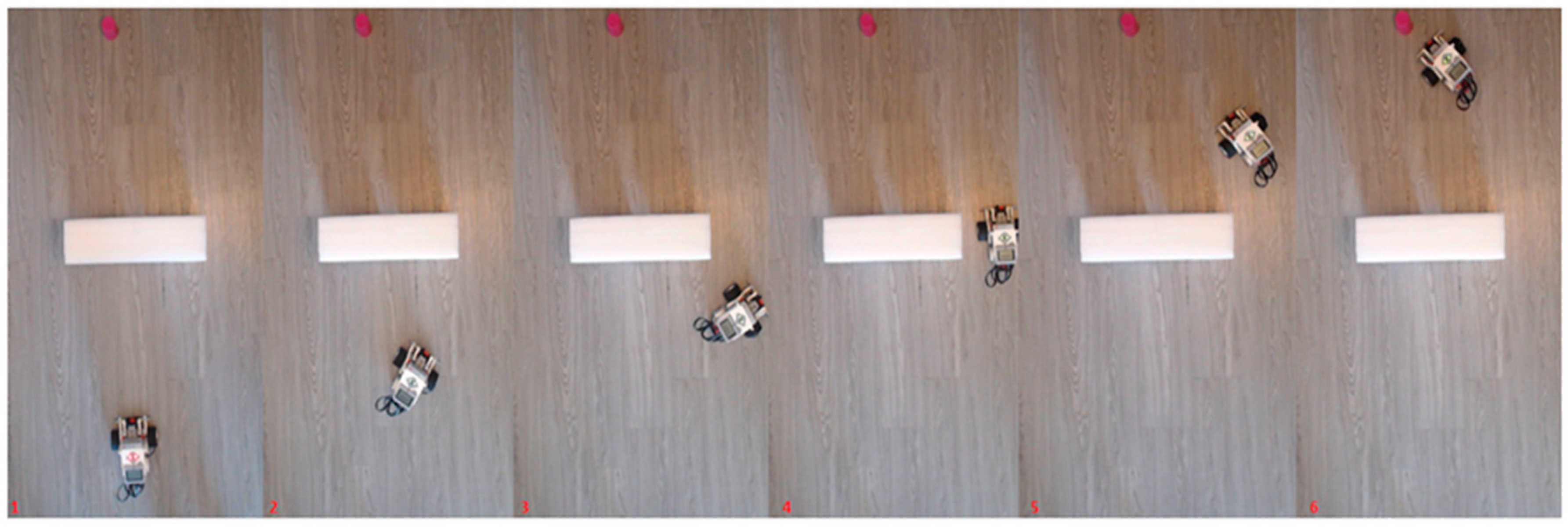
Figure 16. The adaptability, robustness, accuracy and efficiency of the proposed methods can be observed from these experimental results. The real experimental environment is shown in
Figure 14 and
Figure 16. It includes the robot, obstacle and target token. Here are six different frames obtained from the experimental environment. The eye gaze data coordinates, robot path coordinates, and robot wheel speed are stored during the movement of the robot and this data is graphically illustrated. The affection of the relationship between robot speed and gaze point is illustrated in
Figure 18. The effectiveness of the fuzzy rules and suitability of the fuzzy controller on collision-free behavior is shown in
Figure 19.
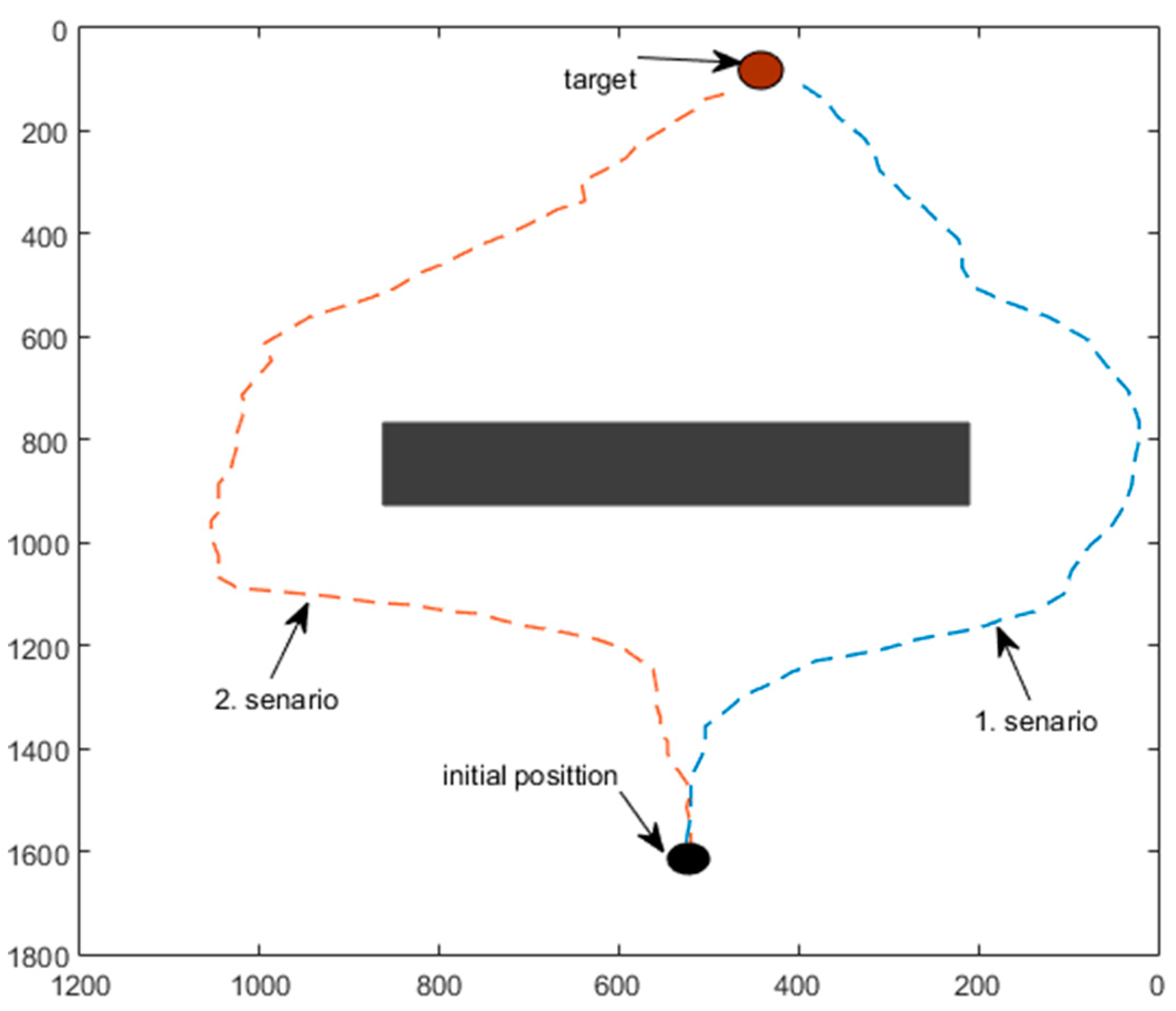
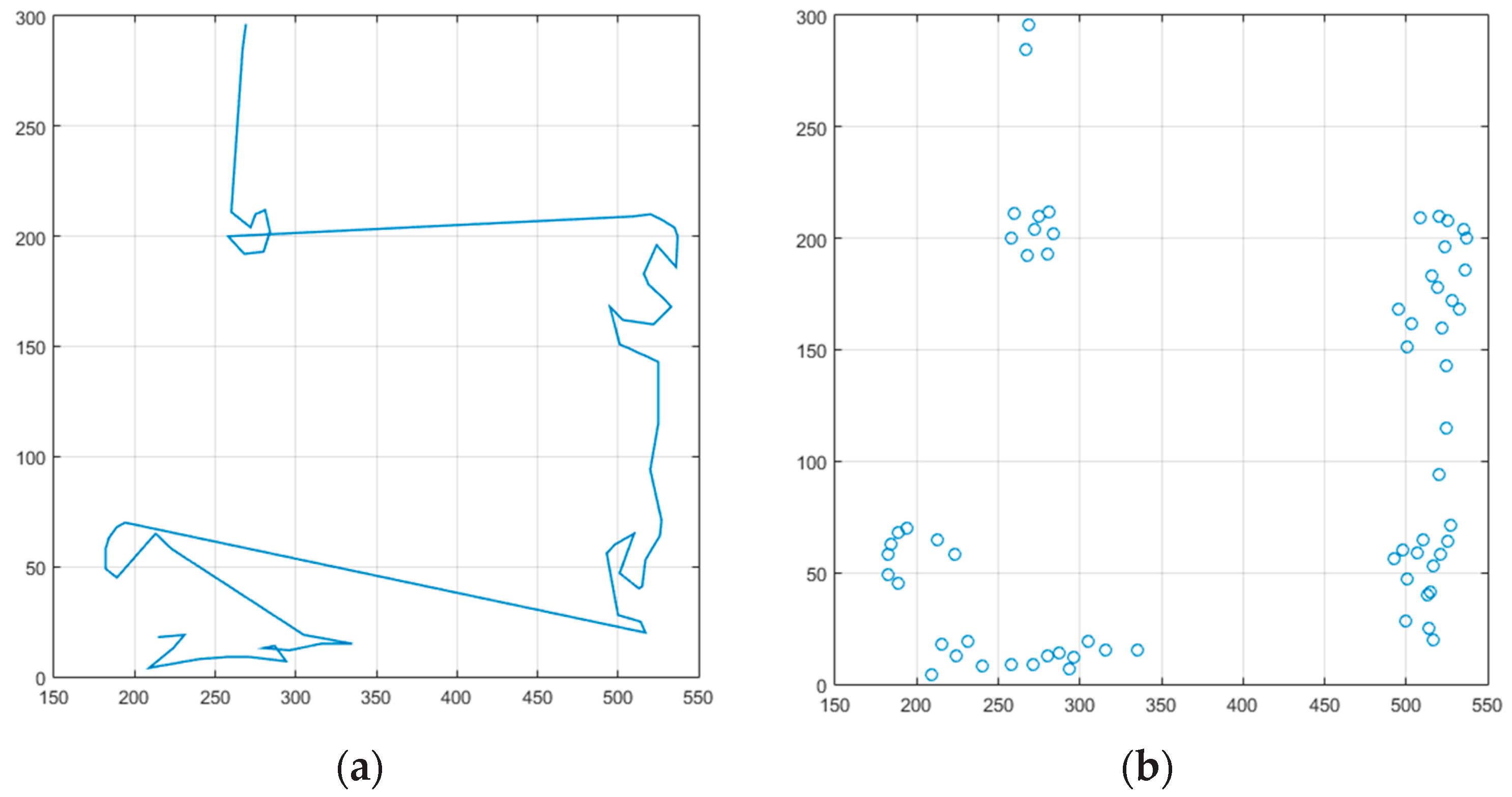
In the first scenario (see
Figure 14), the robot navigates in an uncomplicated environment with one obstacle. Throughout its motion to the target, the mobile robot encounters an obstacle. In this situation, the robot is moving smoothly and without colliding. The real experimentation of this scenario is illustrated in
Figure 14. The eye gaze coordination for this scenario is shown in
Figure 15.
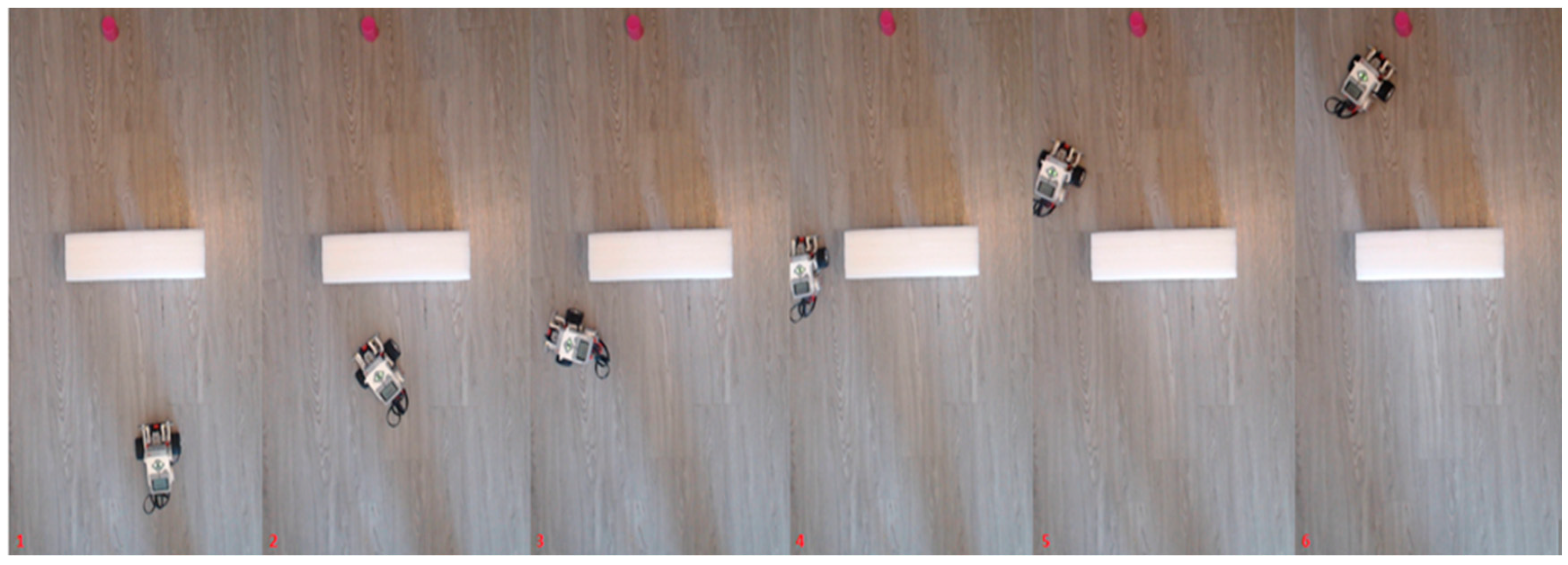
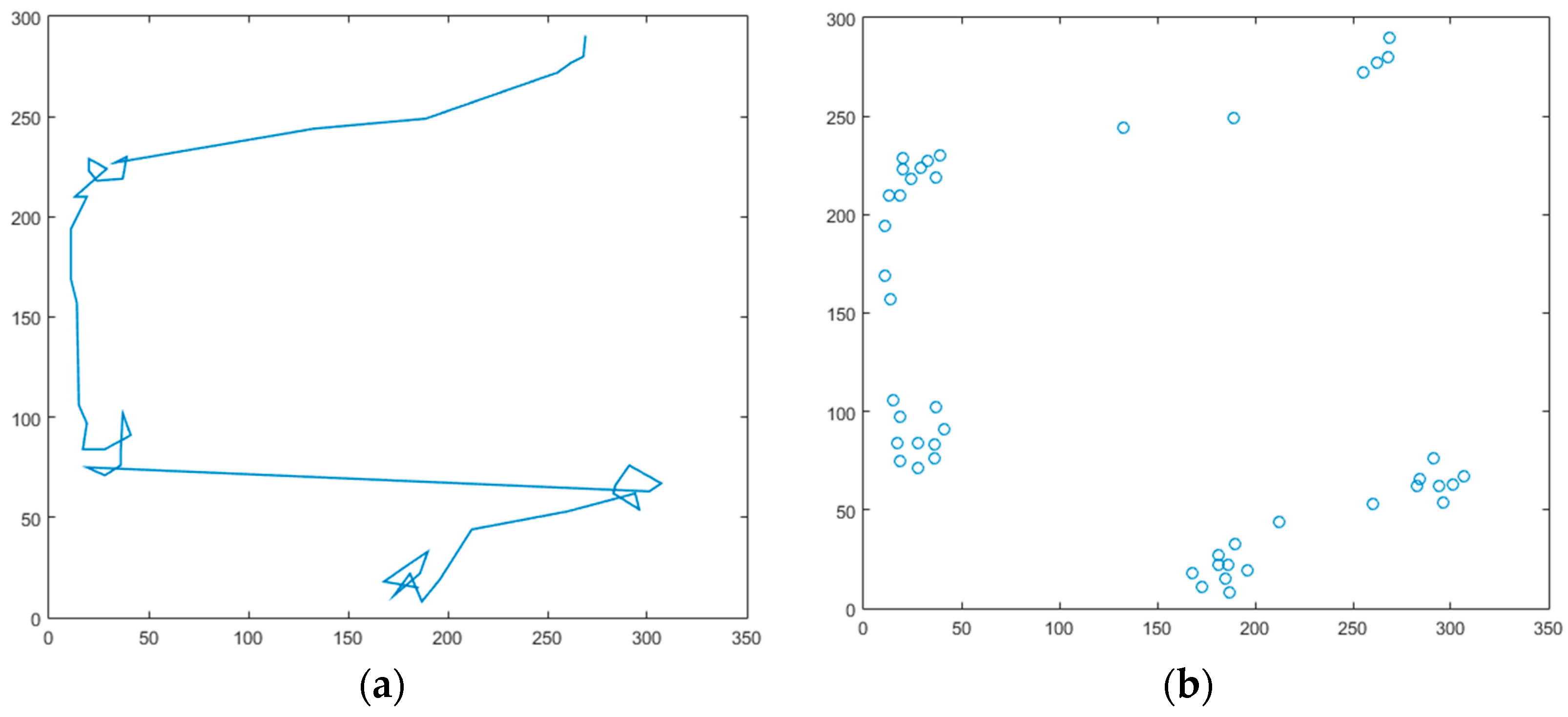
In the second scenario, the user has directed the robot to the left side with the eye movements. It was seen that the mobile robot behaved similarly to its first scenario. The real experimental results are shown in
Figure 16. The plot of this scenario is shown in
Figure 17. The objective of this driving is to confirm the efficacy of the method in different cases. As can be seen from this case, the mobile robot navigates successfully around the obstacles without collision and reach the target.
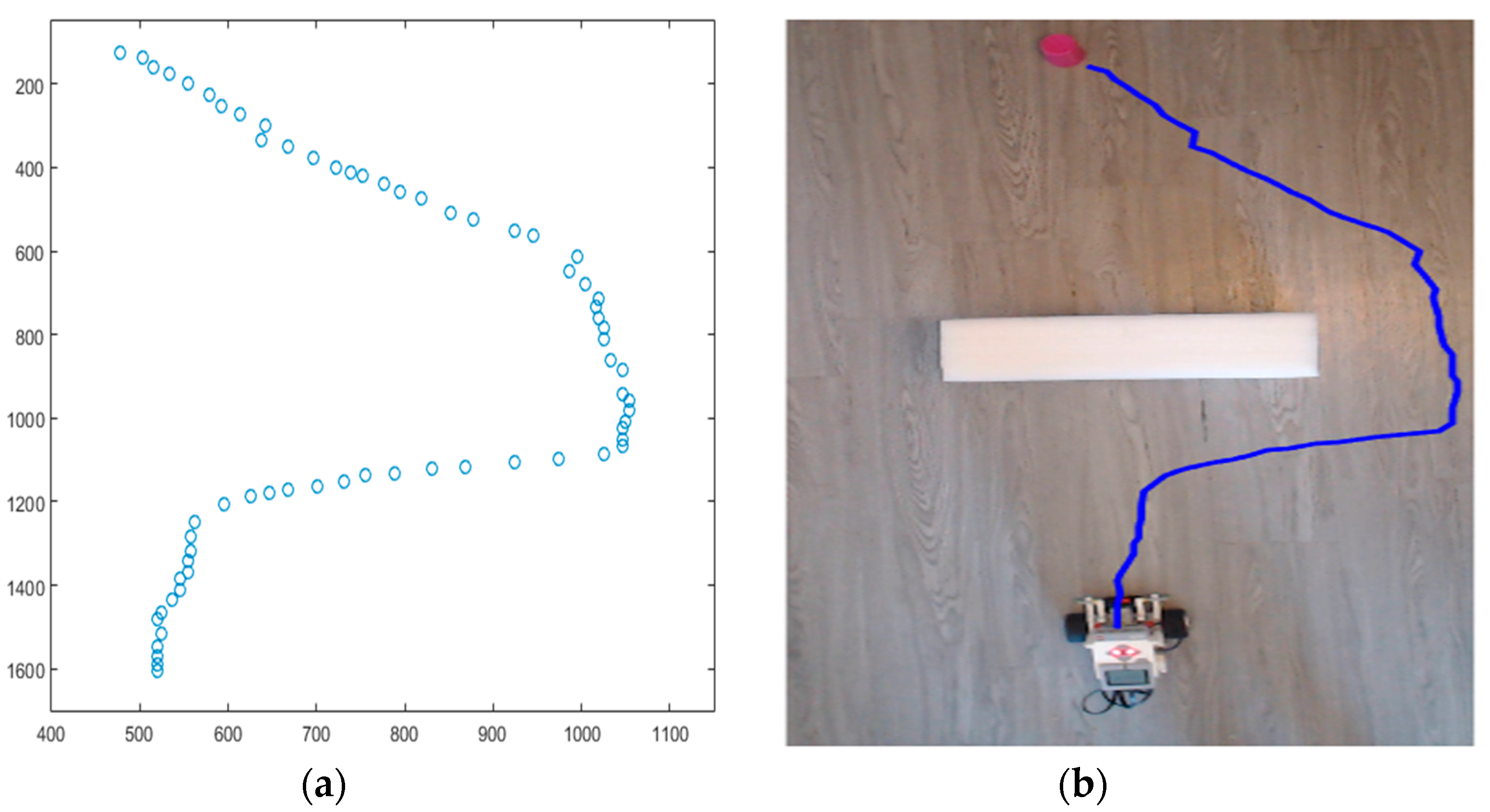
The robot wheel speed for the two scenarios is shown in
Figure 18. And, the Robot trajectory from the experiment of
Figure 14 is shown in
Figure 19.
4. Discussion
From the experiments, the human gaze has been evidenced to be an encouraging modality for GGC. Our proposed method was expanded to explore motion control by straight-gaze input to perform hands-free control of the mobile robot. The gaze-based control system has good potential for future work. We think that this technology has a significant function in facilitating the life of a disabled person. The gaze-based control system is still in its infancy and its function and features need to be further developed in order to be implemented in more complex situations. The use of an eye-based interaction modality can reduce both physical and mental burden. The main aim will be to increase the usability of the system by increasing the learning and ease-of-use by considering the overall efficiency. A low-cost eye-tracking device used in our experiments is crucial in the stability. The user’s head must be stable and the eye tracker must snapshot the eye frame in certain positions. Although this situation is difficult to set-up, it is preferred because it is inexpensive and robust in the gaze position for motion control commands. The profoundly accurate eye trackers are able to present control of vehicles that are as good in term of speed and error as mouse control. It is clear that the differentiation between our model and controlling a wheelchair-based gaze guide drive is using overhead camera images. This type of motion control could be profitable in remote control situations like hazardous, poisonous places where the hands are needed for other tasks. A signification limitation of the current work is that the surveillance system is managed from a fixed location. The correct determination of gaze width and height positions (start and end) is important for the designed controller. When the eyes are closed, the engines are driven to zero and thus the robot is stopped. For this purpose, the sub-program has been audited without choosing the rule base. This is considered as the mobile robot’s go-to-goal behavior. For this reason, the behavior of robot retraction has not been taken into account. This choice was made for the purpose of feasibility in testing a novel idea for socially assistive robots. It is our expectation that a new idea is implemented for target audiences who need socially assisted robots.
The proposed method was implemented for an indoor experiment. As the work accomplished in this paper progressed, many ideas came to mind, which could be discussed in future research, such as outdoor experiments and investigations on how the gaze based control of devices and how it compares with traditional methods such as omnidirectional wheels. These wheels are troublesome individuals compared to the traditional ones. Lastly, our proposed method may sub serve as a simple, secure and affordable method for future gaze guided vehicle control prototypes.
5. Conclusions
In this paper, we proposed a vision-based gaze guide mobile robot control. Application of gaze interaction, wearable, and mobile technology has mainly been conducted on controlling the movement of robots. Users were enabled to control the robot remotely and hands-free by using their eyes to specify the target where they want the robot to move to. A central processing unit executes data communication between the user and the robotic platform. This continuously monitors the state of the robot through visual feedback and send commands to control the motion of the robot. Our experiments include an overhead camera, an eye tracking device, a differential drive mobile robot, vision and IT2FIS tools. This controller produces the required wheel velocity commands to drive the mobile robot to its destination along a smooth path. To achieve this requirement, our methodology incorporates two basic behaviors, map generation and go-to-goal behavior. Go-to-goal behavior, based on an IT2FIS, is more smooth and uniform to progress handling data in uncertainties to produce a better performance. The algorithms are implemented in an indoor environment with the presence of obstacles. Furthermore, the IT2FIS controller was strongly used to control a real-time mobile robot using exact gaze data obtained from human users using an eye tracking system. The differential drive mobile robot (EV3) was successfully commanded by the user’s gaze. This method of interaction is available to most people, including those with disabilities and the elderly, who undermine motor ability. Thus, I would like to express that this technology needs to be developed in order to be able to be used in many fields. This system can also be an alternative or supplement to a conventional control interface such as a mouse or joystick, etc. The results from the proposed technique have been illustrated via simulation and experiments. It is indicated that the intelligent vision-based gaze guided robot control (GGC) system is applicable and the IT2FIS can successfully infer operator intent, modulate speed and direction accordingly. The experimental results obtained are very adequate and verify the efficacy of the proposed approach.


