Article

Development of Lift Control System Algorithm and P-M-E Analysis in the Workplace

by
Inikuro Afa Michael
Department of Computer Engineering, Taras Shevchenko National University of Kyiv, 01033 Kyiv, Ukraine
Appl. Syst. Innov. 2018, 1(4), 38; https://doi.org/10.3390/asi1040038
Submission received: 4 September 2018 / Revised: 7 October 2018 / Accepted: 10 October 2018 / Published: 12 October 2018

Abstract

:
Lifts play an important role in human transportation in multi-storage buildings, which experience continuous improvements to their architecture and structure. As a result of these improvements, the development of efficient lift systems with more programs is required to meet these changes. In this work, a lift control system based on a programmable logic controller (PLC) is introduced, elucidating the development of the lift control algorithm and network based on a dispatching algorithm that utilizes a fuzzy system and exploits the traffic situation and condition. The PLC language ladder logic is implemented to facilitate a reduction in the average waiting time of passengers and the power consumption. Ladder diagrams for different scenarios are compared. The analysis of personnel-machine-environment (P-M-E) system conditions was conducted, examining numerous physical factors that could pose health and safety threats to workers. The present study opens doors for future lift systems studies based on PLC and the estimation of a safe workplace for machines and operators.

1. Introduction

Lifts are essential motor-powered vertical media of transportation in residential, commercial and industrial buildings that play a huge role in the movement of people around these environments. Nowadays, as a result of tremendous development in the structural and architectural engineering in multi-storage buildings, lifts have become inevitable and a key requirement for human transportation [1]. Lifts are used in almost all the multi-storage buildings of metropolitan areas and hence, it is important to replace the traditional relay logic controlled lifts with more programmable technology based lifts for better efficiency, such as PLC [2,3].
These relay controlled systems have several limitations, such as a high fault ratio, difficulty in replacing flawed parts of the automated system and highly complex circuitry. Another drawback is the difficulty in providing fault tolerance using relay logic. PLC serves as a more enhanced replacement for designing modern lift control systems to circumvent these shortcomings and improve the troubleshooting of the system by allowing for easy monitoring of the inputs and outputs via human-machine interaction (HMI) devices, such as the HMI–LED indicator, better operational speed, reliability and relatively lower costs compared to other programmable control systems [4,5,6,7,8]. PLC has been successfully demonstrated in several control studies, including lift control systems [9,10,11,12,13,14].
When designing lifts with PLC, the dispatching algorithm is one of the most important aspects in the control system and therefore, an efficient algorithm can reduce the average waiting time of passengers to a remarkable average of 25 s or less and also reduce the power consumption of the lift system. Six main types of dispatching algorithms are generally implemented, which are namely: (i) Collective up—CU; (ii) Collective down—CD; (iii) Selective up—SU; (iv) Selective down—SD; (v) Selective-collective up—SCU; and (vi) Collective-selective down—CSD algorithms [5]. The choice of the preferred algorithm is selected on a specific instance based on the traffic amount and percentage.
To achieve an efficient control system, the algorithm employs a fuzzy scheme to improve control based on logical reasoning and implementing systems through programmed expert knowledge. The concept of a fuzzy control system was first introduced by L.A. Zadeh as he introduced the concept of linguistic variables that serve as fuzzy sets (i.e., input variables in the fuzzy control) [15,16]. The fuzzy system is normally divided into four main parts, which are namely fuzzy knowledge rules, fuzzifier, fuzzy inference engine and the defuzzifier. This is done to transfer the input signal into linguistic terms and the inference makes the calculations and decision to prioritize certain lift assignment. Furthermore, the output information is converted by the defuzzifier into a single signal that serves as the control instructions [17]. The concept of fuzzy control and fuzzy logic has been extended to lift control and group control systems. The early to mid 1990s led to a boom in the implementation of fuzzy logic in lift systems [18,19,20,21,22]. Kim et al. [23,24] demonstrated a design based on a fuzzy control model that identifies traffic patterns and implements the traffic patterns and traffic mode based on information, such as traffic percentage, time, area-weight and other linguistic terms. Dewen et al. further demonstrated a fuzzy logic in group supervisory control, which demonstrates an optimum lift vehicle assignment with control devices [25].
Recent studies have introduced novel approaches for applying fuzzy logic in order to improve the expert prediction of lift control as compared to the old methods to increase efficiency in lift systems and energy optimization [26,27,28]. Jamaludin et al. further extended conventional fuzzy lift systems by introducing a self-tuning mechanism to adapt the control system to the continually changing traffic with better precision [29,30]. Some recent studies have demonstrated a lift system that employs fuzzy control systems and PLC. PLC is shown to be fast and adaptable to multiple inputs and outputs to meet traffic demands, which makes it suitable for this present study [31,32]. Other benefits of using PLC in this type of design is that it can be incorporated in more complex applications and can be easily adapted to other systems, such as the control of automated machinery systems, including cranes and robotic arm manipulator [33,34].
P-M-E refers to the optimal relationship between personnel (people in the work place and responsible for the operation of machine), machine (the computer and other control systems) and the environment (the prescribed work conditions for personnel–machine interaction). Even though fuzzy logic systems are very intelligent, they still lack the full mastery of the entire system, especially relating to installation, troubleshooting and maintenance. As a result, lifts can be considered to be a purely personnel-machine-environment system. Therefore, they require operators to oversee the optimal functioning. Sometimes, depending on the number of operators required, the conditions of the workplace change. Hence, the need for this analysis is to achieve a safe, highly efficient and cost effective system and work environment for the operators [35,36]. Lifts are considered to be vital assets in corporate buildings and as a result, its maintenance is paramount.
In this paper, the development of the lift control network is briefly introduced in Section 2, with the development of the control algorithm explained; the fuzzy control system described based on its input variables, fuzzification, fuzzy inference and defuzzification processes; and the PLC tasks illustrated. The ladder logic diagram is introduced and compared for different scenarios in Section 2.2. Finally, the analysis of the P-M-E system in the workplace is discussed in Section 3. The present study presents a simplified lift control system using a PLC algorithm based on fuzzy logic scheme that can be easily implemented and adapted to other control system designs.

2. Control Network Development

The lift system controller design operates with division zoning technique and a fuzzy control system for the efficient computing of fitting values Fp for a quicker lift hall-call. These fitting values computation is based on numerous lift performance conditions, such as the waiting time of the passengers, load capacity and distance between floor hall-calls. The controller implements a fuzzy system in traffic pattern recognition, while the division zoning scheme helps in tailoring the controller according to the patterns from the fuzzy system [23,24,37].
The fuzzy system used in this work is divided into three main parts: (i) fuzzification; (ii) fuzzy inference; and (iii) defuzzification. The fuzzifier helps to classify the traffic patterns by converting the signal into a set of fuzzy variables. The signal is translated into five linguistic terms, which are namely very large (VL), large (L), medium (M), small (S) and very small (VS). The traffic patterns are received in terms of the number of passengers going in different directions, which is namely upwards (UP) or downwards (DN), and also in the case of steady state traffic. The priority is given to the direction with higher traffic, i.e., if UP = VL and DN < VL (L, M, S, VS), Fp = High Priority is thus assigned to UP.
Once the traffic direction is identified, the input information is passed to the fuzzy inference engine along with extra linguistic variables, such as (a) waiting time (WT); (b) space availability in lifts (SA); and (iii) distance between the elevators and distance of hall-calls floors and destination floors (Dist). The inference engine serves as the fuzzy decision block, which calculates the entire Fp to set the priority for the number of lifts (N) based on a rule sets (Fp = High, Medium or Low) as shown in Table 1.
This means that for a smaller loading, closer proximity of lifts, shorter waiting times and higher number of passengers waiting, the priority is assigned to a lift with highest combined Fp. These details are sent to the defuzzifier, which generates a single output based on the total priority assigned. This is conducted on the number of lifts (N) and the traffic mode is subsequently set.
The defuzzification process employs the center of gravity method, which assigns the priority according to the total fitting values for 1 to N lifts. The lift with the highest total priority fitting value is assigned as the main preference and the information is passed as a single real traffic output. This output value serves as control instructions for responding to lifts according to the traffic data and hall-call assignment.
In this section, we will look at the development of the lift control algorithm and the programming languages used.

2.1. Development of Lift Control Algorithm
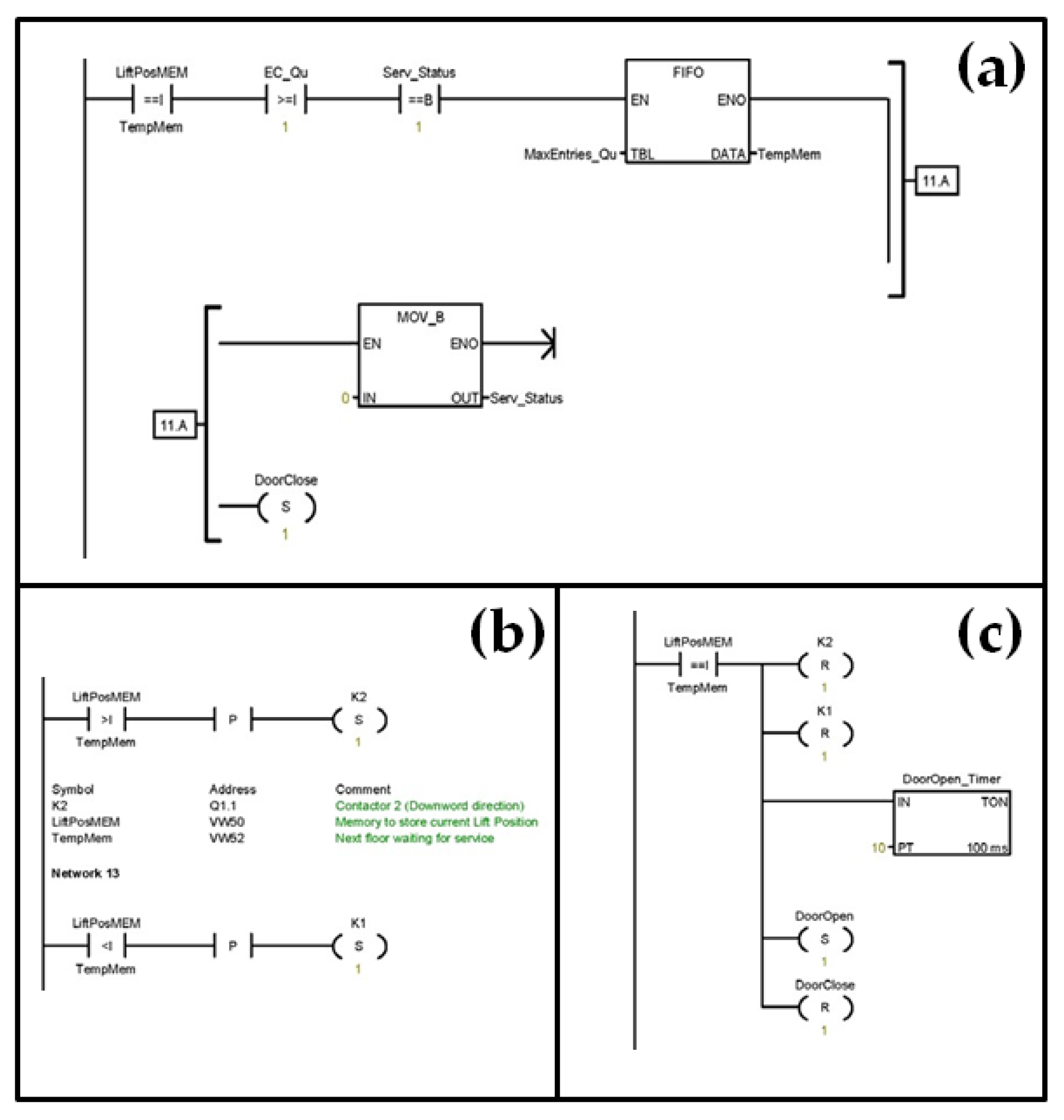
As stated previously, the algorithm employed is used to control the lift system through the division zoning and a fuzzy system. This takes into account the fact that the division zones represent lifts in the building, which are dependent on the hall-call requests. The present algorithm is comprised of three phases: (i) the identification in phase 1; (ii) the response in phase 2; and (iii) the execution in phase 3.
In phase 1, the algorithm assigns zones with the aid of a fuzzy traffic controller, which was similarly described in the work of Patiño-Forero et al. [31], that identifies if a lift is free or not by analyzing information, such as the occupation and capacity of the lift on the floor from which the hall-call was made. Furthermore, it also utilizes the information related to whether this call was intended to go upwards or downwards.
Phase 2 is only initiated in a case of a free lift. In this case, the fuzzy system fitting value calculations for quick hall responses are initiated by the algorithm. Once the lift is considered to be occupied, phase 3 commences, in which the algorithm executes the inputted information from the hall-call until the lift is free again. The lift control algorithm employs an open platform communication (OPC) between the fuzzy control system and the PLC, which is suitable for the reception of data from devices, such as HMI devices. The flowchart for the algorithm design is shown in Figure 1.
The main task of the design is related to the logic that is essential for controlling the movement of the lift between the floors of the building. The main conditions are stated as follows. (1) There must be upward and/or downward button(s) to make a hall-call. If there is no call, the lift retains its current position. In the cases of multiple calls from different floors, the response is made based on the time order of when the call was made. (2) The door of the lifts will have a programmed door that opens and closes automatically on every floor of the building.
PLC programming languages that are generally used in lift control system design include the follows: (i) Structure text (ST); (ii) Instruction list (IL); (iii) Function block diagram (FBD); (iv) Sequence function chart (SFC); and (v) Ladder (logic) diagrams (LL/LD). Ladder logic is a graphical programming language that is extracted from the circuitry evolution of the relay control wiring [13]. In this present work, the ladder logic, which is the most commonly used language to program the PLC, was employed.

2.2. Ladder Logic

The ladder logic network is established based on the pre-selected PLC prerequisites, such as the input signal from the hall-call. Some of the ladders that are responsible for tracking the status of different pushes are described in Figure 2 and Figure 3.
Ladder diagrams are interpreted from left to right and from top to bottom. The rungs, which are also referred to as networks, have several control elements with a single output coil. Table 2 describes the logic input information from the ground floor as illustrated in network 1 of Figure 2a.
It is important to take a look at the ladders tracking the touch sensors. We can see that from Figure 2, the normal open contact here is responsible for receiving and storing the information received from the touch sensor. After this, the second symbol stores the position of the lift. The information is sent to the counter for processing and the position of the lift is stored in the counter ready for execution.
The ladder diagram in Figure 3a is responsible for combining and storing all the conditions received (i.e., ladders for checking all required conditions). Based on the results of this condition, the output (i.e., motor drive) is driven by the ladder seen in Figure 3b. The motor executes its action from the output received from the other ladders. The examples of the conditions include: next floor waiting for service, the current lift position and next destination, etc.
The door of the lift is also automated based on the movement of the lift, which means that when the lift is in motion, the door of the lift will be closed and will remain open for the rest of the time. The ladder to achieve this goal is shown in Figure 3c.

3. P-M-E System Analysis in the Workplace

Labor protection is important for creating a workplace with safe and healthy labor terms. The major labor protection terms are examined in order to reduce the influence of any dangerous work environment factors on workers [38,39]. Therefore, P-M-E system analysis is done as described in Figure 4, showing the relationship of personnel (P), machine (M) and environment (E).
The important part of this project was conducted in the workplace of a small lab with dimensions of 8 m × 6 m × 4 m. Accordingly, the area of the room is equal to 48 m2. The area of the windows was 3 m × 2 m = 6 m2. The workplace has double-sided windows and a door, which allows for an amount of air entrance for ventilation. The width of the evacuation exit is equal to 2 m × 0.8 m = 1.6 m2. In the workplace, there are five people (p = 5) working on different projects and they all use computers to operate particular functions for these projects. An equipment in the workplace feeds from the three-phase, four-wire electric system with the dead earthed neutral, as shown in Figure 5. This has a tension of 380/220 V and a working tension of 220 V. Furthermore, the working frequency was 50 Hz.
With regards to the normal terms of labor, the volume of workplace should not be less than 20 m3 and area of 6 m2 forone operator of the PC. In this present study, we ran the following calculations: the area (A) of working place = 8 m × 6 m = 48 m2 and the volume (V) = 8 m × 6 m × 4 m = 192 m3. At present, the area/no. of people = 192/5 = 10.6 m2 and volume/People = 192/5 = 41 m3. Hence, the volume and area on one operator of the working place are in accordance to the terms of labor [40,41].
Task 1.
Calculation of current passing through the body of man at a unipolar and bipolar touch.
In this variant, a man touches two phase wires (biphasic touch). In this case, a current flowing through the human body can be calculated using this formula:
I people = V linear R people  
where Vlinear is the linear voltage = 380 V; Rpeople is the resistance of people = 1.4; and Ipeople: current of people = unknown. To calculate the value of current, we use the following formula:
I people = 380 1.4 × 10 3 = 0.27   A
This current (271 mA) with 50-Hz frequency causes cardiac arrest without fibrillation. If the effect of the current last 1 to 2 s and causes no damage to the heart, a person usually resumes normal activity on their own after the power failure.
Task 2.
Calculation of crossing of send-offs and cables for the economy of density current.
The formula for its calculation is given as:
S ec = I max J ec
where Imax is the current line during the normal work of network with a SI unit of A; and Jec is the economical current density with a SI unit of A/mm2, which is determined depending on the material and time of usage of the maximal loading. In the case of bare copper conductors with current, S ec = 9 3.0 = 3   mm 2 . Anything less than 3 mm2 can cause electrocution due to the high current flowing through the copper wire, which increases the heat and causes the wire to change to heated red color.
Task 3.
Estimation of shut-down ability of devices maximal current defense.
The short circuit current, Ish is calculated as I sh = V ph Z ph 0 , where Vph is the phase tension with a SI unit of V; and Zph-0 is an impedance of loop a «phase-zero» with a SI unit of Ω.
The device of maximal current defense is provided by the reliable disconnection of users of electric power from the network if a condition is executed, which is calculated as:
I nom I sh E ^
where Inom is the nominal current of the fusible insertion of safety device. The current electromagnetic insertion of circuit breaker on short-circuit has a SI unit of A. Furthermore, E ^ is a coefficient of multiples of current (according to NPAOP 40.1-1.21-98 [42] for fuse E ^ = 3 or for the electromagnetic breaker, E ^ = 1.4 or 1.25).
For a fuse:
V ph = 220   v ;   Z ph 0   =   20   Ω ;   I sh = V ph Z ph 0 = 220 20 = 11 V Ω
  I nom I sh E ^ = 11 3 = 3.66
I nom 3.66
Another important task is the calculation of the necessary amount and types of fire-extinguishers. For safety purposes, the computer room should be provided with these types of denotation of fire extinguisher: (i) BBk-1,4, BBk-2 Carbon-dioxide and (ii) BBk-3,5, BBk-5 Carbon-dioxide. Fire safety is an important condition of security of the personnel, property, society and state from fires. In addition to the provision of fire extinguishers, alarm systems are installed for the detection of fire by initiating audiovisual signals as hazard warnings.

4. Conclusions

In this paper, the development of the lift control system algorithm is discussed. It is shown that the network development is based on the traffic patterns and the zoning division using the fuzzy lift control system. The ladder logics for understanding the evolution of the electrical circuitry of the PLC controlled lift system are discussed and compared.
The personnel-machine-environment system analysis is conducted to ensure not only the safety of workers but also the smooth operation of the machine and the workplace. The present study provides an insight for future studies that should focus on the implementation of lift control systems and creating an excellent working environment for their efficient operation.

Funding

This research received no external funding.

Acknowledgments

The author acknowledges the support of the research technicians of the Faculty of Computer Engineering of the Kharkov National University of Radio-electronics and the regular research visits hosted.

Conflicts of Interest

The author declares no conflict of interest.

References

  1. Cooper, D.A.; Inglis, J.; Barney, G. Elevator and Escalator Micropedia, 6th ed.; GBA Publications: Sedbergh, UK, 2009; ISBN 978-0952569688. [Google Scholar]
  2. Allen-Bradley. Converting Relays to Programmable Controllers; Rockwell Automation Publication: Wilwaukee, WI, USA, 2001; ISBN 1761-WP001A-EN-P. [Google Scholar]
  3. Erickson, K.T. Programmable Logic Controllers: An Emphasis on Design and Application, 2nd ed.; Dogwood Valley Press LLC: Rolla, MO, USA, 2011; ISBN 978-0-9766259-2-6. [Google Scholar]
  4. All about Circuits—Programmable Logic Controller (PLC). Available online: https://www.allaboutcircuits.com/textbook/digital/chpt-6/programmable-logic-controllers-plc/ (accessed on 3 September 2018).
  5. Blikoontech—S7 200 PLC Based Elevator Control System. Available online: https://www.blikoontech.com/s7-200-plc-based-elevator-control-system/ (accessed on 3 September 2018).
  6. Zhang, J.; He, J.; Hu, F. Design of elevator group control simulation test bed based on PC-PLC. J. Changchun Univ. Sci. Technol. 2009, 32, 105–108. [Google Scholar]
  7. Liu, X. Development of elevator monitor system based on the Fieldbus. J. Electr. Electron. Educ. 2008, 30. Available online: http://en.cnki.com.cn/Article_en/CJFDTOTAL-DQDZ200801022.htm (accessed on 3 October 2018).
  8. Koshti, K.M.; Joshi, S.M. Design of Human machine interface for PLC based automation system. IFAC Proc. Vol. 2007, 40, 343–346. [Google Scholar] [CrossRef]
  9. Sharma, S.; Ladakhi, T.Y.; Tiwary, A.P.; Pradhan, B.B.; Phipon, R. Application of PLC for elevator control system. In Proceedings of the International Symposium on Devices MEMS, Intelligent Systems & Communication, Gangtok, India, 12–14 April 2011; pp. 4–7. [Google Scholar]
  10. Zheng, S.; Liu, F. The design of elevator control system based on PLC and configuration. In Advances in Computer Science, Intelligent System and Environment; Jin, D., Lin, S., Eds.; Springer: Berlin/Heidelberg, Germnay, 2011. [Google Scholar]
  11. Singh, G.; Agarwal, A.; Jarial, R.K.; Agarwal, V.; Mondal, M. PLC controlled elevator system. In Proceedings of the 2013 Students Conference on Engineering and Systems (SCES), Allahabad, India, 12–14 April 2013; pp. 1–5. [Google Scholar]
  12. Yang, X.; Yang, X.; Zhu, Q.; Xu, H. Design and practice of an Elevator control system based on PLC. In Proceedings of the IEEE Workshop on Power Electronics and Intelligent Transportation System, Guangzhou, China, 2–3 August 2008. [Google Scholar]
  13. Ron Carter, S.B.; Selvaraj, A. Design and implementation of PLC based elevator. Int. J. Comp. Appl. 2013, 63, 4–10. [Google Scholar]
  14. Tharani, K.; Gupta, S.; Puri, A.; Khera, R.; Kumar, A. PLC based multi-floor elevator control system. Int. J. Robot. Autom. 2015, 4, 202–208. [Google Scholar]
  15. Zadeh, L.A. Fuzzy sets. Inf. Control 1965, 8, 338–353. [Google Scholar] [CrossRef] [Green Version]
  16. Zadeh, L.A. Outline of a new approach to the analysis of complex systems and decision processes. IEEE Trans. Syst. Man Cybern. 1973, 1, 28–44. [Google Scholar] [CrossRef]
  17. Sharma, D. Designing and Modeling Fuzzy control systems. Int. J. Comp. Appl. 2011, 16, 46–53. [Google Scholar] [CrossRef]
  18. Aoki, H.; Sasaki, K. Group supervisory control system assisted by artificial intelligence. Elev. World 1990, 2, 70–80. [Google Scholar]
  19. Tobita, T.; Fujino, A.; Inaba, H.; Yoneda, K.; Ueshima, T. An elevator characterized group supervisor control system. In Proceedings of the International Conference on Industrial Electronics, Control and Instrumentation, Kobe, Japan, 28 October–1 November 1991; pp. 1972–1976. [Google Scholar]
  20. Umeda, Y.; Uetani, K.; Ujihara, H.; Tsuji, S. Fuzzy theory and intelligent options. Elev. World 1989, 7, 86–91. [Google Scholar]
  21. Nakai, S.; Kubo, S.; Imasaki, N.; Yoshitsuku, T.; Kiji, J.; Endo, T. Elevator group control system with fuzzy neural network model. In Proceedings of the 4th IEEE International Conference on Fuzzy Systems, Yokohama, Japan, 20–24 March 1995; pp. 37–38. [Google Scholar]
  22. Powell, B.A.; Sirag, D.J. Fuzzy logic—A new way of thinking about complexities of dispatching elevators. Elev. World 1993, 9, 78–84. [Google Scholar]
  23. Kim, C.; Seong, K.A.; Lee-Kwang, H.; Kim, J.O.; Lim, Y.B. A fuzzy approach to elevator group control system. IEEE Trans. Syst. Man Cybern. 1995, 25, 985–990. [Google Scholar]
  24. Kim, C.; Seong, K.A.; Lee-Kwang, H.; Kim, J.O. Design and implementation of a fuzzy elevator group control system. IEEE Trans. Syst. Man, Cybern. Part A Syst. Hum. 1998, 28, 277–287. [Google Scholar]
  25. Dewen, Z.; Hui, Q.; Tao, Z.; Guanghui, S.; Lili, W. The fuzzy logic inference decision system of elevator group supervisory control. IFAC Proc. 1998, 31, 117–120. [Google Scholar] [CrossRef]
  26. Kim, H.M. A design for elevator group controller of building using adaptive dual fuzzy algorithm. KSME Int. J. 2001, 15, 1664–1675. [Google Scholar] [CrossRef]
  27. Onuoha, J.C.; Odii, J.N. Improving the efficiencies of elevator systems using fuzzy logic. Comput. Inf. Syst. Dev. Inform. 2012, 3, 29–34. [Google Scholar]
  28. Fernández, J.; Cortés, P.; Gaudix, J.; Muñuzuri, J. Logic Elevator Group Control System for energy optimization. Int. J. Inf. Technol. Decis. Mak. 2013, 12, 591–617. [Google Scholar] [CrossRef]
  29. Rahim, N.A.; Ping, H.W.; Jamaludin, J. A novel self-tuning scheme for fuzzy logic elevator group controller. IEICE Electron. Express 2010, 7, 892–898. [Google Scholar] [CrossRef] [Green Version]
  30. Jamaludin, J.; Rahim, N.A.; Ping, H.W. An elevator group control system with a self-tuning fuzzy logic group controller. IEEE Trans. Ind. Electron. 2010, 57, 4188–4198. [Google Scholar] [CrossRef]
  31. Patiño-Forero, A.A.; Muñoz, D.M.; Caribé de Carvalho, G.; Llanos, C.H. Modeling of an elevator group control system using programmable logic control and destination control system. ABCM Symp. Ser. Mechatron. 2010, 4, 433–441. [Google Scholar]
  32. Coşkum, Y.M.; Karali, M. The realization of a control algorithm and its PLC based program able to authorize four different ranks of priority to elevator uses. Int. J. Appl. Math. Electron. Comp. 2013, 4, 416–420. [Google Scholar]
  33. Tafreshi, S.A.; Klamroth-Marganska, V.; Nussbaumer, S.; Riener, R. Real-time closed-loop control of human heart rate and blood pressure. IEEE Trans. Biomed. Eng. 2015, 62, 1434–1442. [Google Scholar] [CrossRef] [PubMed]
  34. Škulavík, T. PLC-Based Fuzzy Control System for a Robotic Manipulator. Ph.D. Thesis, Slovak University of Technology, Bratislava, Slovak, 2013. [Google Scholar]
  35. Song, X.; Xie, Z. Application of man-machine-environment system engineering in coal mines safety management. Proc. Eng. 2014, 84, 87–92. [Google Scholar]
  36. Kosuge, K.; Fujisawa, Y.; Fukuda, T. Control of mechanical system with man-machine interaction. In Proceedings of the IEEE/RSJ International Conference on Intelligent Robots and Systems, Raleigh, NC, USA, 7–10 July 1992; pp. 87–92. [Google Scholar]
  37. Lee, C.C. Fuzzy logic in control systems: Fuzzy logic controller—Part I. IEEE Trans. Syst. Man Cybern. 1990, 20, 404–418. [Google Scholar] [CrossRef]
  38. Liu, L.; Sun, X.; Song, K. Analysis on the man-machine-environment collaborative teaching method for mining engineering major. Int. J. Emerg. Technol. Learn. 2016, 11, 42–46. [Google Scholar] [CrossRef]
  39. Tyosuojelu.fi—Machinery and Tools. Available online: http://www.tyosuojelu.fi/web/en/working-conditions/machinery-and-tools (accessed on 3 October 2018).
  40. Real Commercial—How Much Office Space Business Needs. Available online: https://www.realcommercial.com.au/news/much-office-space-business-need (accessed on 3 October 2018).
  41. Standard NEN 1824:2010—Ergonomics—Ergonomic Requirements for the Surface of (Workplaces in) Administration and Office Spaces; ICS-CODE13.180-91.040.20; Nederlands Normalisatie-Instituut: Delft, Netherlands, 2010.
  42. UTEM-Group. Accreditation of Training Center at UTEM for Training on Labor Protection. Available online: www.utem-group.com/en/news/accreditation-of-training-center-at-utem-for-training-on-labor-protection (accessed on 3 October 2018).
Figure 1. Flowchart representing the algorithm execution in different phases.
Asi 01 00038 g001
Figure 2. Ladder diagrams for: (a) Reception and storage of information from touch sensor on the ground and first floor represented as networks 1 and 2; and (b) Storage of information related to the current position of the lift.
Asi 01 00038 g002
Figure 3. Ladder diagrams for: (a) Combining, storing and checking all required conditions; (b) Driving the conditions in the output; and (c) Automated movement of the doors of the lift.
Asi 01 00038 g003
Figure 4. The general structure of the P-M-E system with descriptions in Table 3.
Asi 01 00038 g004
Figure 5. The body of a man at a unipolar and bipolar touch.
Asi 01 00038 g005
Table 1. Fuzzy knowledge rules for waiting time (WT), space availability (SA) and distance (Dist).
IFTHEN (Fp)
WT = Short High
WT = MediumMedium
WT = LongLow
SA = LargeHigh
SA = MediumMedium
SA = SmallLow
Dist = LessHigh
Dist = MediumMedium
Dist = HighLow
Table 2. Logic input information from the ground floor as seen in Figure 2.
SymbolAddressComment
indcatr_GndQ0.0indicator of ground floor request
Max Entries_QuVWOmaximum no. of entries in the queue/starting address of table
Req_Gnd_Floor10.0request coming from ground floor
Table 3. List of connections in the general system of P-M-E shown in Figure 4.
Number of ConnectionDirectionsComment
1P1-M1Influence of personnel on management
2M1-P1State information machine processed by personnel
3M1-TWInfluence of machine on the goal of work
4TW-P3Influence of the goal of work on the psycho-physiological state of personnel
5P3-P1Influence of the state of organism of personnel on quality of his work
6M2-P3Personnel under the influence of dangerous production factors
7M3…M7-EInfluence of machine on an environment
8E-P3…P7Influence of environment on the state of organism of personnel
9E-M1Influence of environment on the machine
10P1-M2Influence of personnel on the emergency state of machine
11P2-EInfluence of personnel as a biological object on an environment
12P3-P2Influence of the psycho-physiological state on the intensity of exchange of matters between an organism, environment and physiology of personnel
13M1-M2Necessary information for making emergency influence
M2-M1Managing emergency influences
AThe system of external control A- P1Managing information about technological process from the external control of the system

