Indoor Autonomous Vehicle Navigation—A Feasibility Study Based on Infrared Technology


Abstract
:1. Introduction
2. Methods
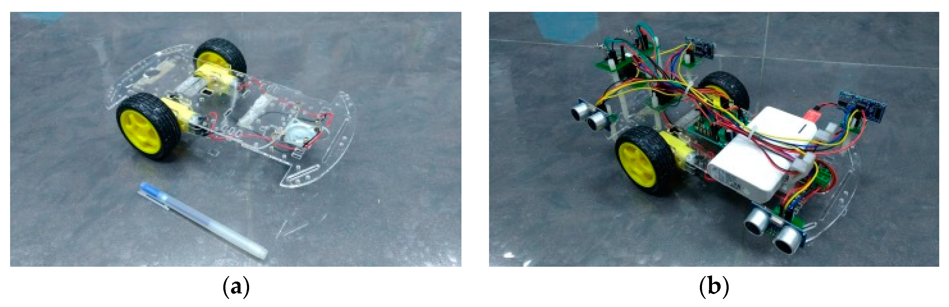
2.1. Mechanical
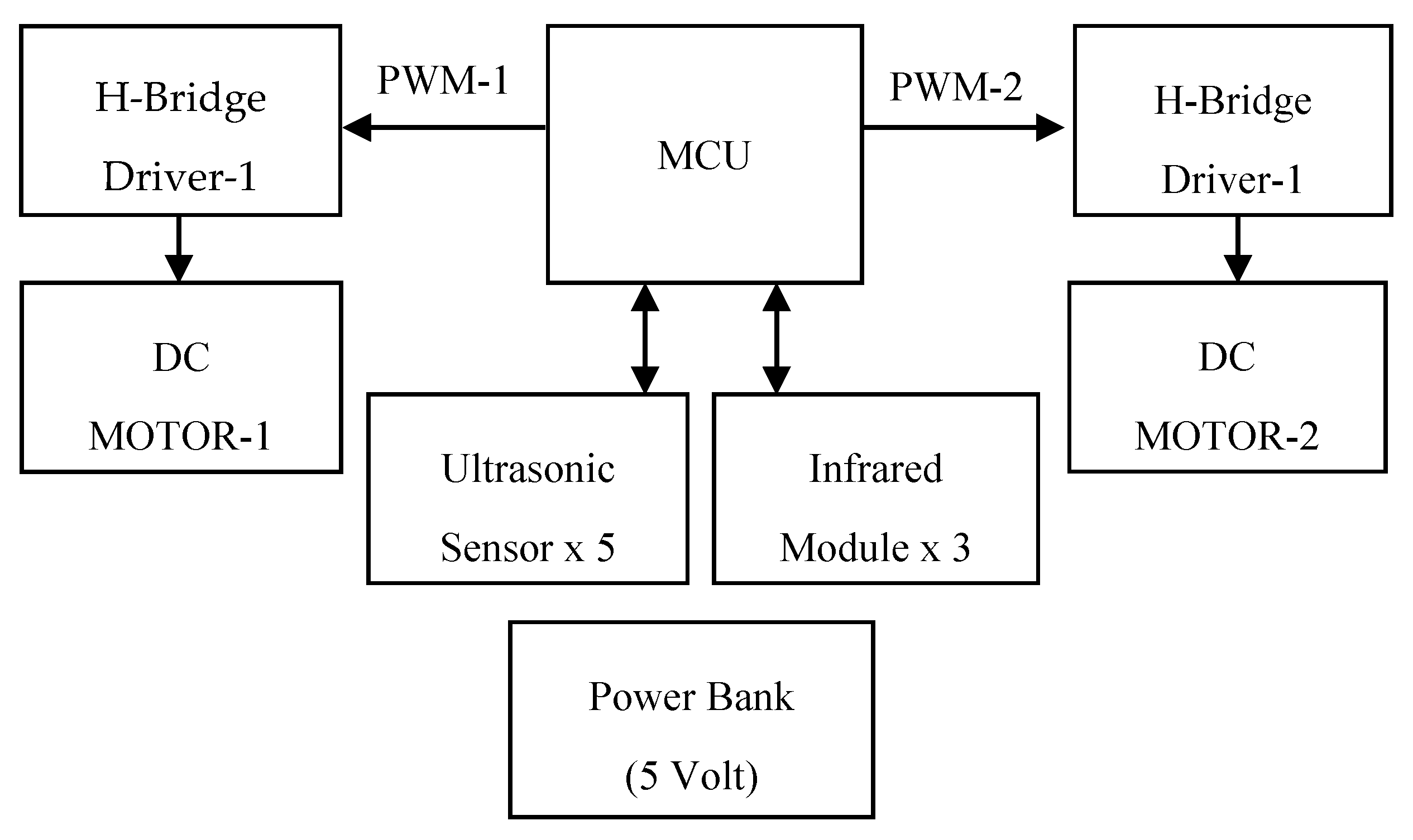
2.2. Electronic
2.2.1. Motion Control
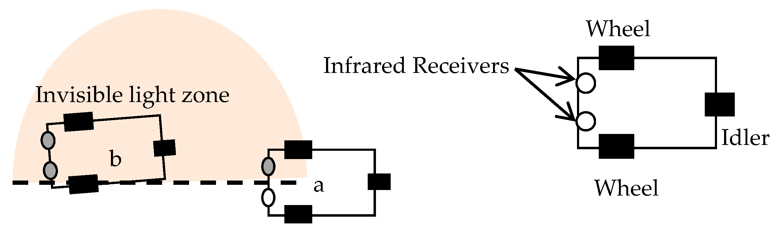
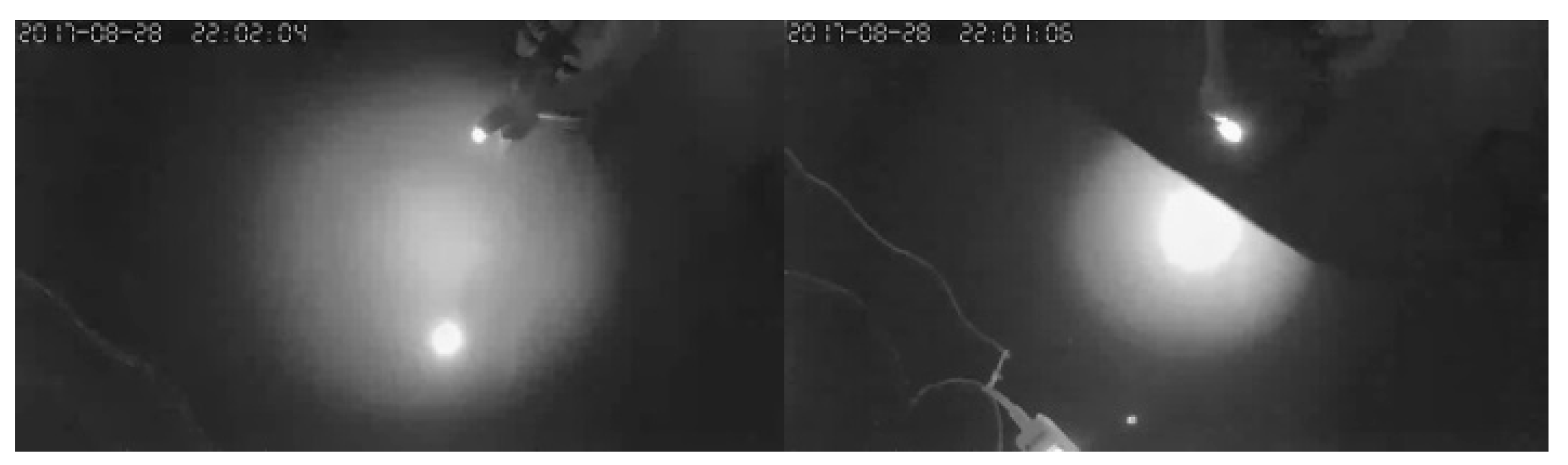
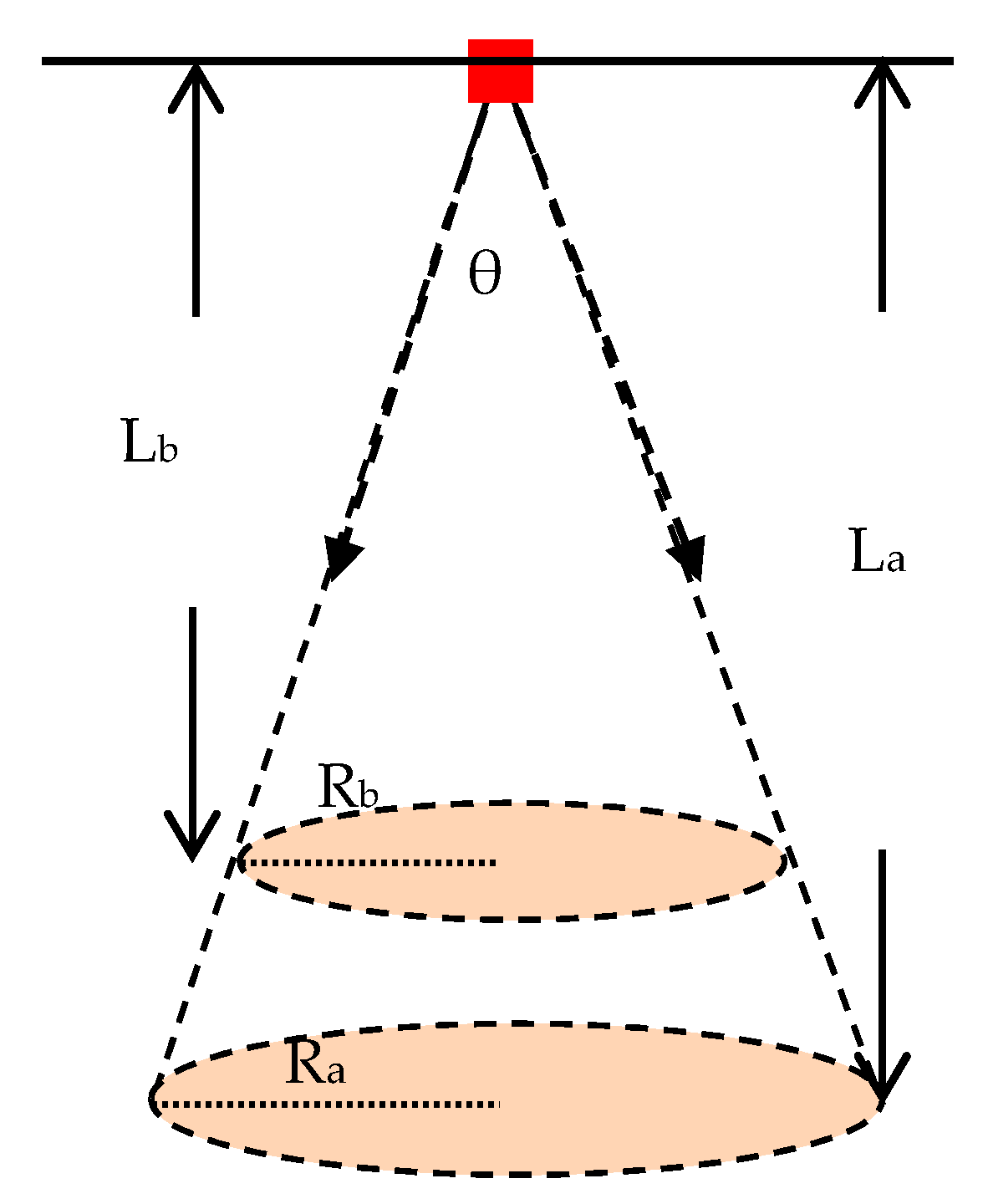
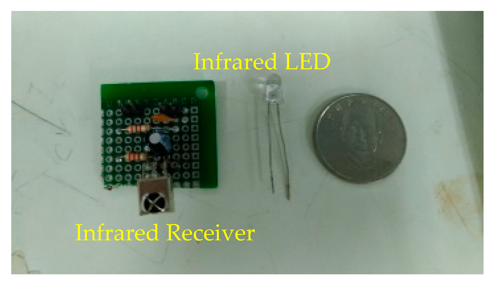
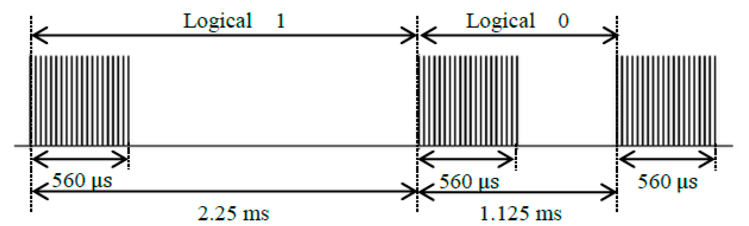
2.2.2. Infrared Module
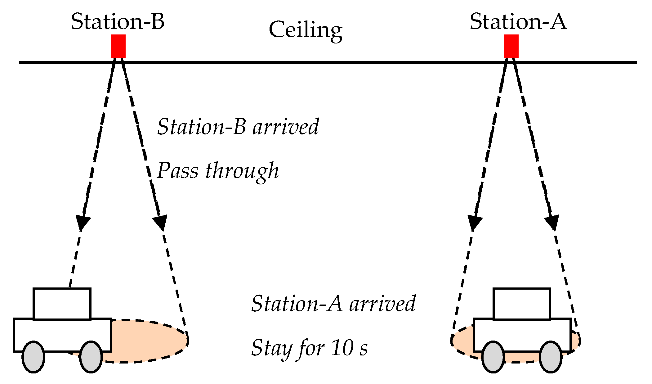
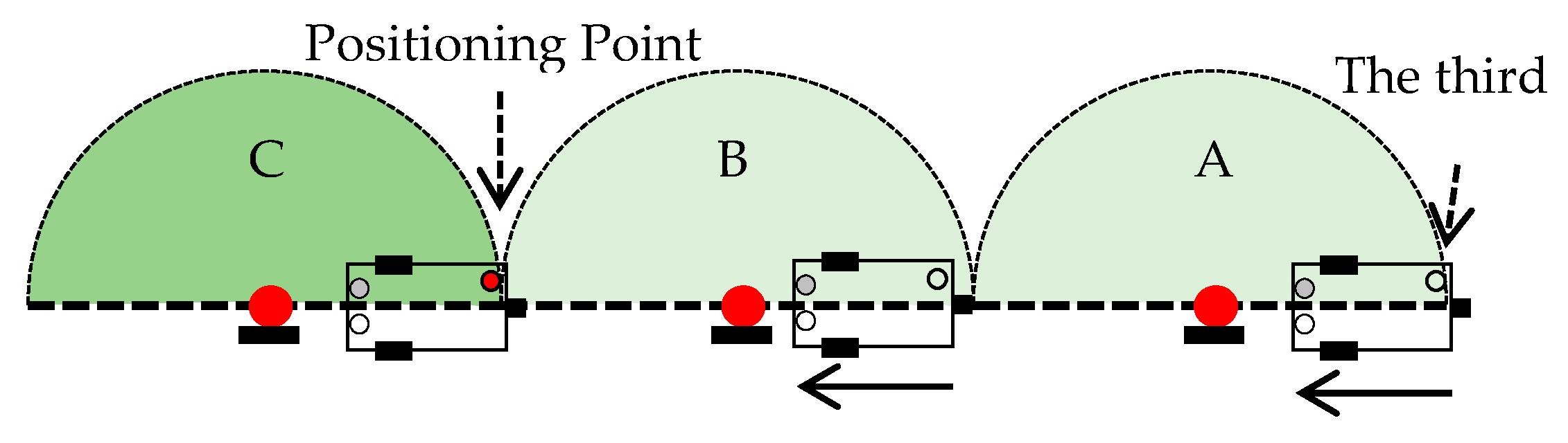
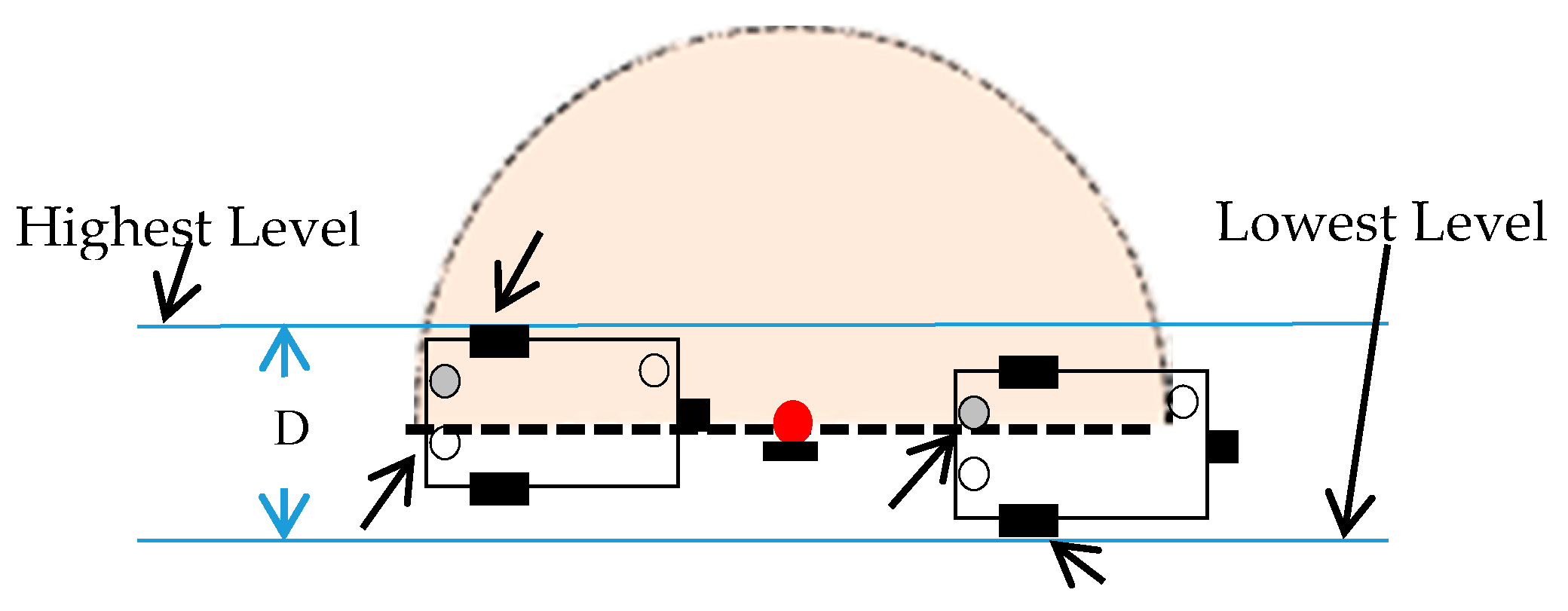
2.2.3. Positioning
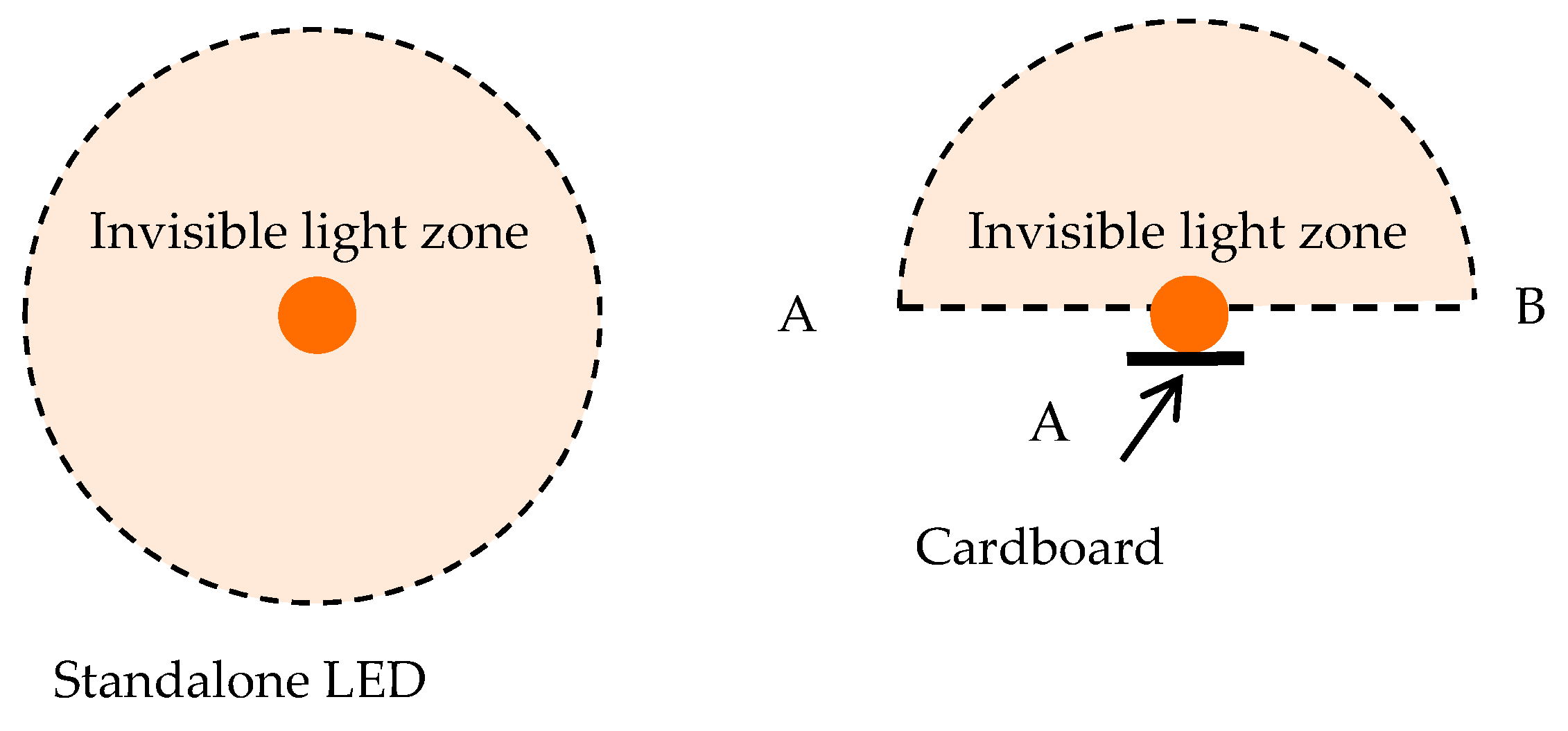
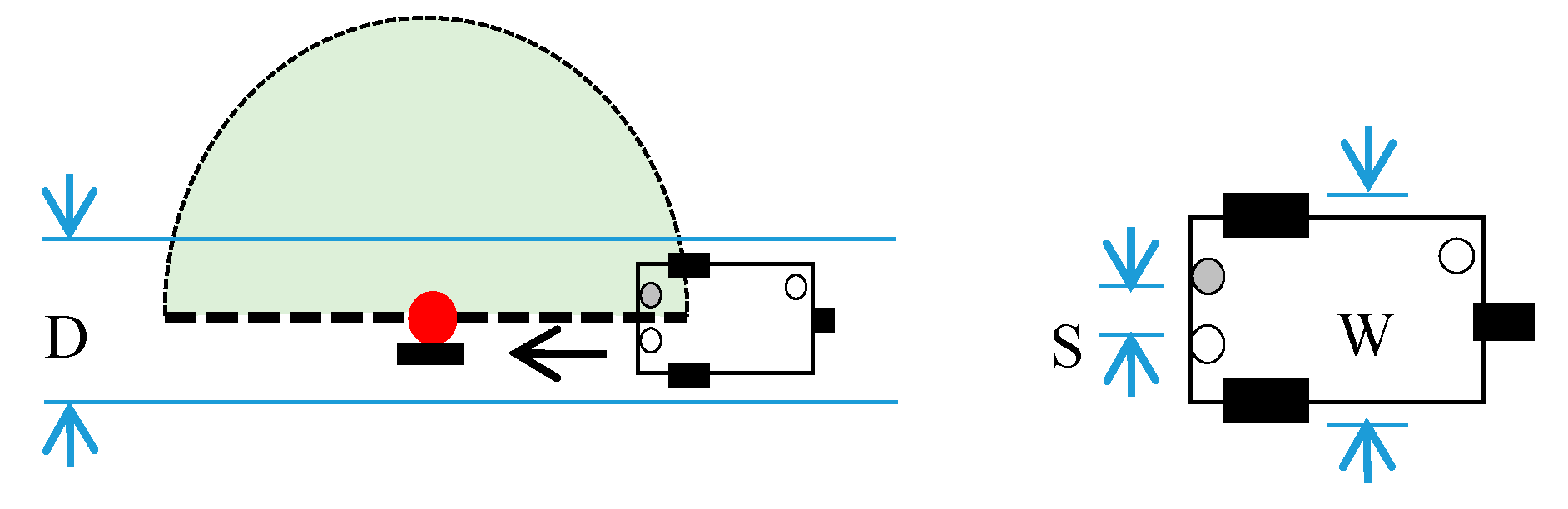
2.2.4. Invisible Route
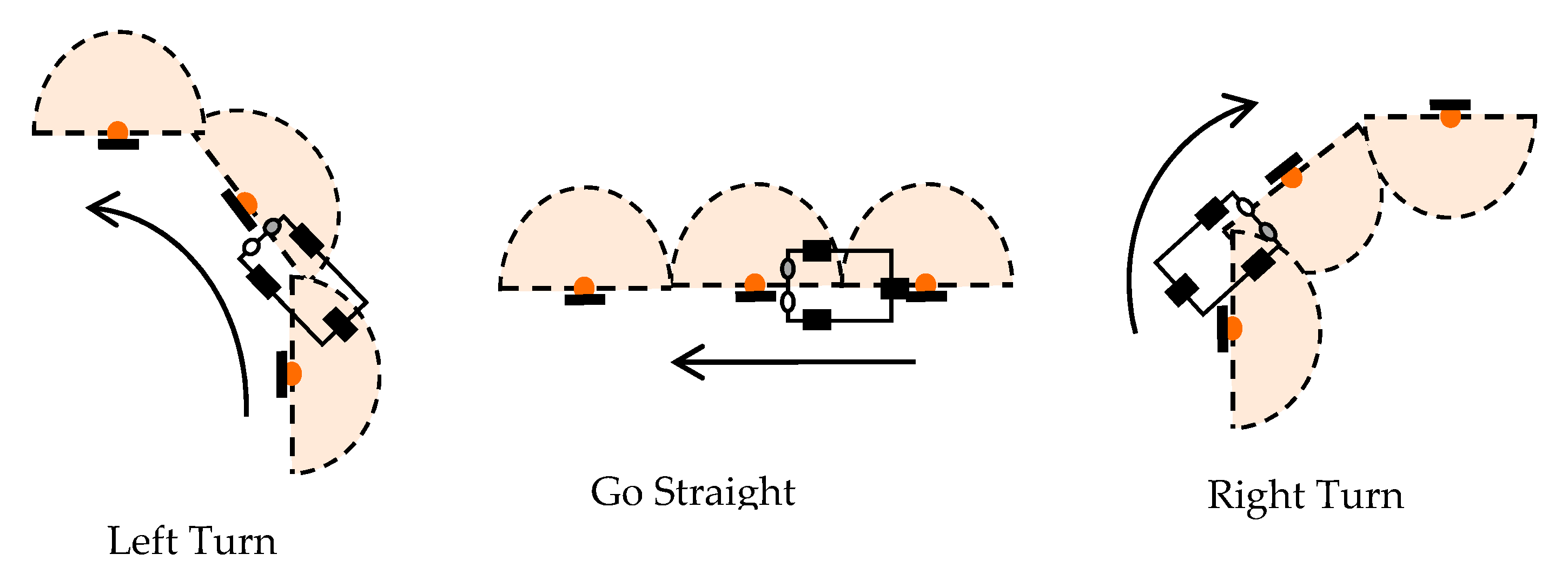
2.2.5. Path Planning
3. Results and Discussion
3.1. Experimental setups
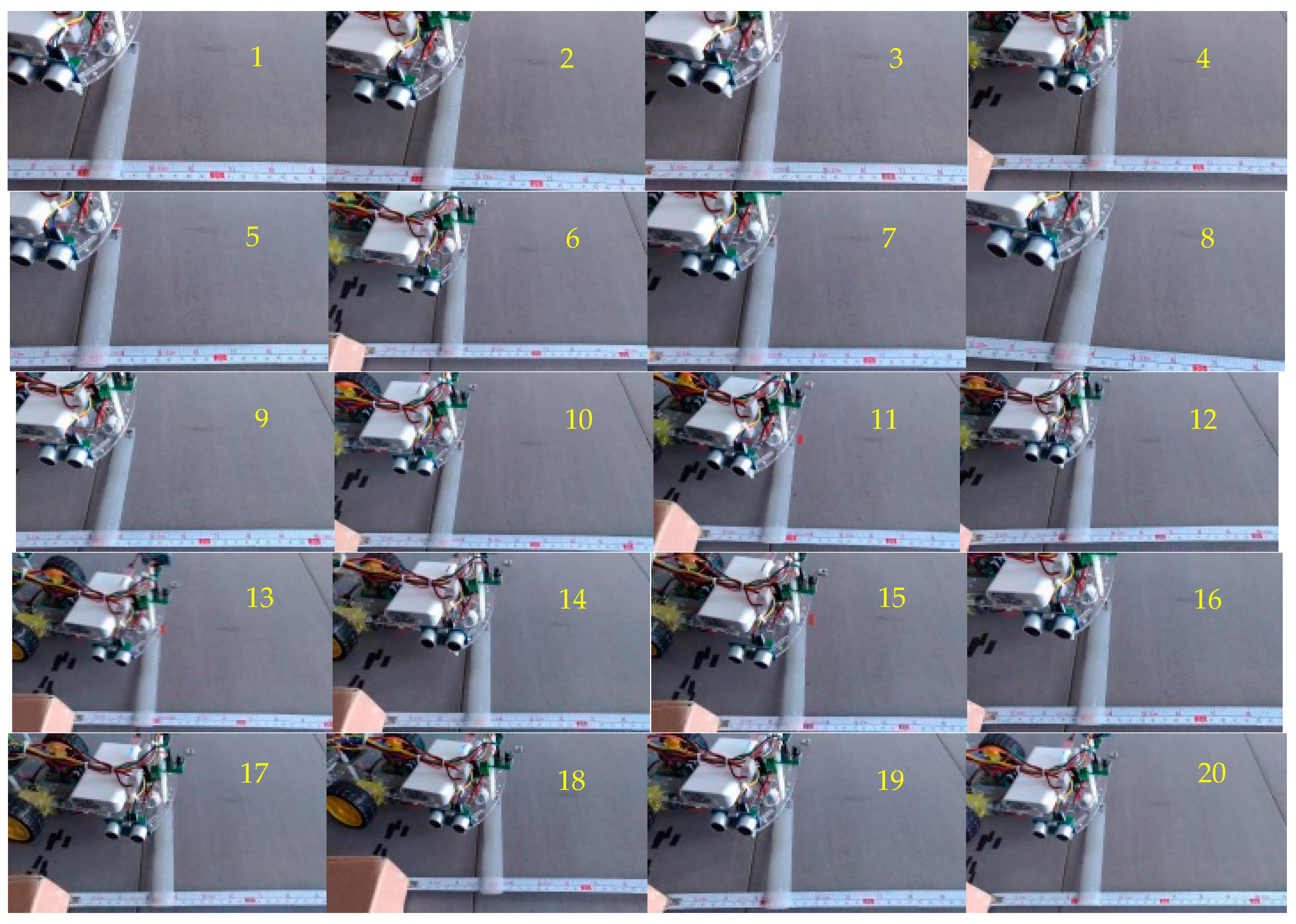
3.2. The Accuracy of Positioning
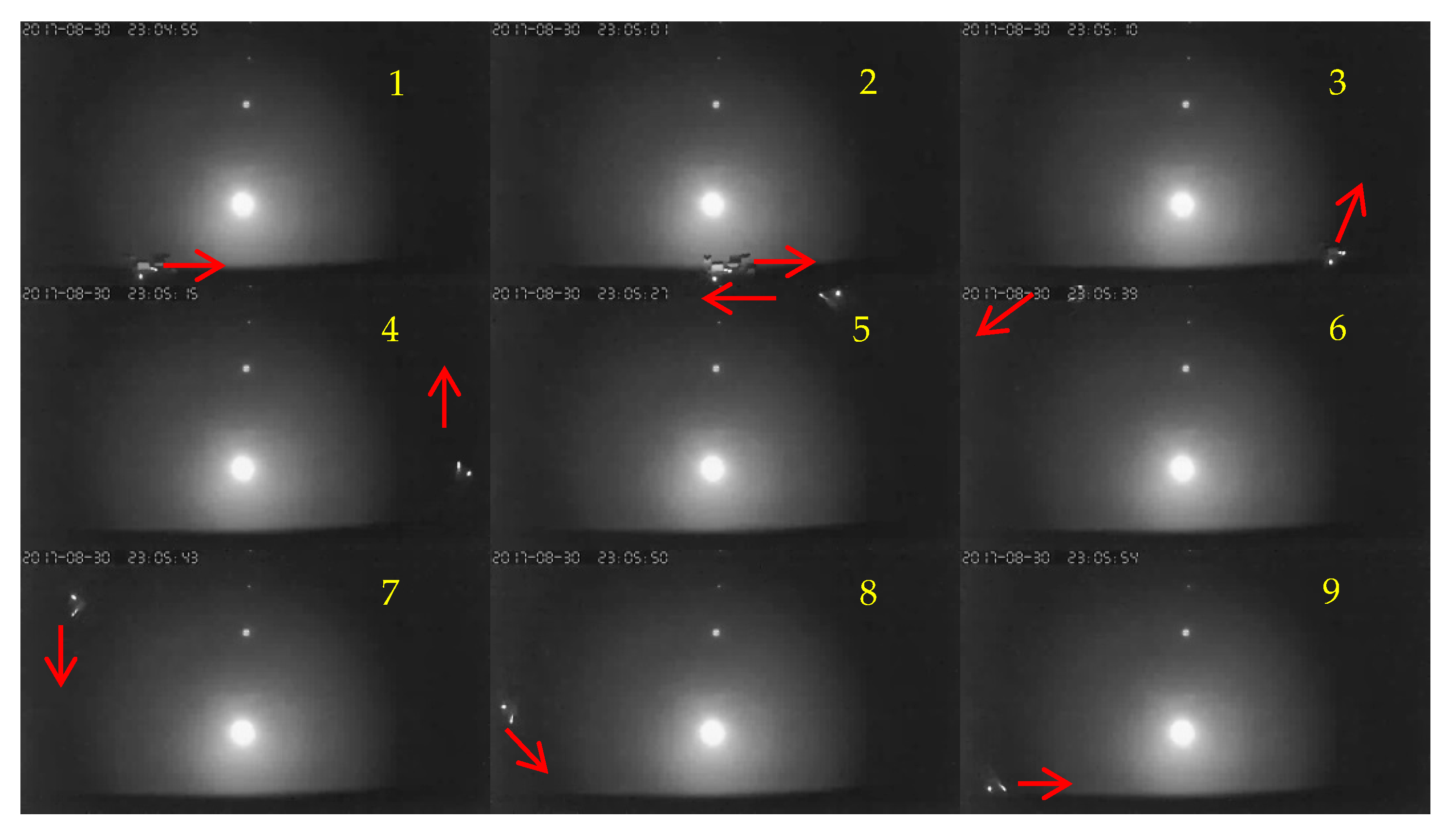
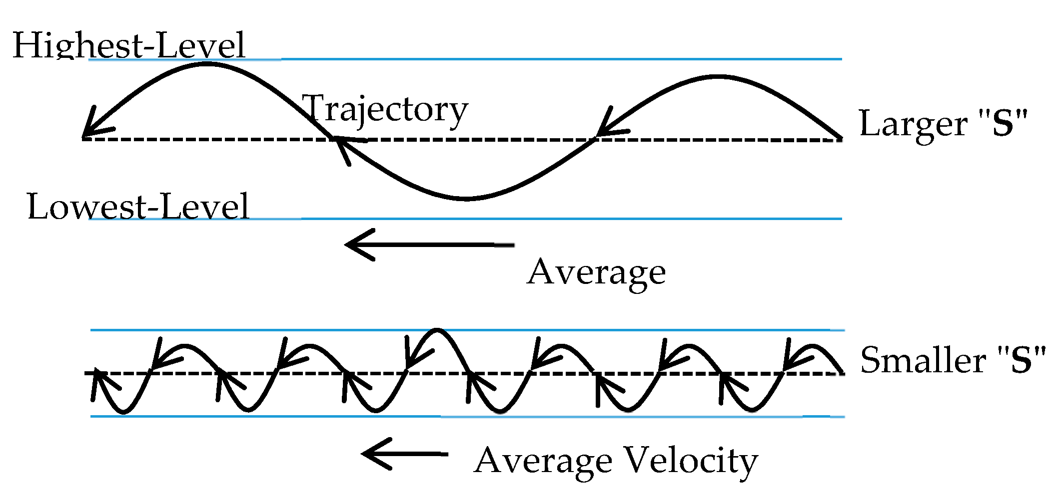
3.3. Trajectory Analysis of Path
4. Conclusions
Supplementary Materials
Conflicts of Interest
References
- Liu, R.; Koch, A.; Zell, A. Path following with passive UHF RFID received signal strength in unknown environments. In Proceedings of the Intelligent Robots and Systems (IROS), Vilamoura, Portugal, 7–12 October 2012. [Google Scholar]
- Liu, R.; Yuen, C.; Do, T.N.; Tan, U.X. Fusing Similarity-based Sequence and Dead Reckoning for Indoor Positioning without Training. IEEE Sens. J. 2017, 17, 4197–4207. [Google Scholar] [CrossRef]
- Liu, R.; Yuen, C.; Do, T.N.; Jiao, D.; Liu, X.; Tan, U.X. Cooperative Relative Positioning of Mobile Users by Fusing IMU Intertial and UWB Ranging Information. In Proceedings of the IEEE International Conference on Robotics and Automation (ICRA 2017), Singapore, 29 May–3 June 2017; pp. 5623–5629. [Google Scholar]
- Ting, S.L.; Kwok, S.K.; Tsang, A.H.C.; Ho, G.T.S. The Study on Using Passive RFID Tags for Indoor Positioning. Int. J. Eng. Bus. Manag. 2011, 3, 9–15. [Google Scholar] [CrossRef]
- Weekly, K.; Zou, H.; Xie, L.; Jia, Q.S.; Bayen, A.M. Indoor occupant positioning system using active RFID deployment and particle filters. In Proceedings of the 2014 IEEE International Conference on Distributed Computing in Sensor Systems, Marina Del Rey, CA, USA, 26–28 May 2014. [Google Scholar]
- Zhao, Y.; Dong, L.; Wang, J.; Hu, B.; Fu, Y. Implementing indoor positioning system via ZigBee devices. In Proceedings of the 42nd Asilomar Conference on Signals, Systems and Computers, Pacific Grove, CA, USA, 26–29 October 2008. [Google Scholar]
- Yang, C.; Shao, H.R. WiFi-based indoor positioning. IEEE Commun. Mag. 2015, 53, 150–157. [Google Scholar] [CrossRef]
- Marvelmind Robotics. Precise (±2 cm) Indoor GPS: For Autonomous Robots, Copters and VR. 2017. Available online: https://marvelmind.com/.
- Run, R.-S.; Yen, J.-C.; Tsai, C.-Y. A Low Cost Implementation of GPS Guided Driverless Cars. In Proceedings of the 5th IEEE Conference on Industrial Electronics and Applications (ICIEA2010), Taichung, Taiwan, 15–17 June 2010. [Google Scholar]
- Run, R.-S.; Chang, Y.-C.; Cheng, F.-C. A Straightforward Approach of Automatic Parking System-“Training-Recording-Play Back”. In Proceedings of the 2012 IEEE International Symposium on Circuits & Systems (ISCAS), Seoul, Korea, 20–23 May 2012. [Google Scholar]


| No. | 1 | 2 | 3 | 4 | 5 | 6 | 7 | 8 | 9 | 10 | 11 | 12 | 13 | 14 | 15 | 16 | 17 | 18 | 19 | 20 |
|---|---|---|---|---|---|---|---|---|---|---|---|---|---|---|---|---|---|---|---|---|
| Offset (mm) | +4 | +5 | −15 | −5 | −15 | −7 | −15 | −7 | −6 | −16 | −30 | +2 | −25 | −14 | −29 | −9 | −5 | −13 | 0 | +2 |
| No. | 1 | 2 | 3 | 4 | 5 | 6 | 7 | 8 | 9 | 10 | 11 | 12 | 13 | 14 | 15 | 16 | 17 | 18 | 19 | 20 |
|---|---|---|---|---|---|---|---|---|---|---|---|---|---|---|---|---|---|---|---|---|
| Left (mm) | 94 | 95 | 96 | 96 | 95 | 96 | 95 | 96 | 94 | 94 | 93 | 94 | 94 | 94 | 95 | 94 | 94 | 95 | 94 | 96 |
| Right (mm) | 265 | 267 | 268 | 267 | 266 | 266 | 266 | 265 | 264 | 265 | 263 | 263 | 263 | 264 | 265 | 265 | 265 | 266 | 264 | 265 |
© 2018 by the authors. Licensee MDPI, Basel, Switzerland. This article is an open access article distributed under the terms and conditions of the Creative Commons Attribution (CC BY) license (http://creativecommons.org/licenses/by/4.0/).
Share and Cite
Run, R.-S.; Xiao, Z.-Y. Indoor Autonomous Vehicle Navigation—A Feasibility Study Based on Infrared Technology. Appl. Syst. Innov. 2018, 1, 4. https://doi.org/10.3390/asi1010004
Run R-S, Xiao Z-Y. Indoor Autonomous Vehicle Navigation—A Feasibility Study Based on Infrared Technology. Applied System Innovation. 2018; 1(1):4. https://doi.org/10.3390/asi1010004
Chicago/Turabian StyleRun, Ray-Shine, and Zhi-Yu Xiao. 2018. "Indoor Autonomous Vehicle Navigation—A Feasibility Study Based on Infrared Technology" Applied System Innovation 1, no. 1: 4. https://doi.org/10.3390/asi1010004
APA StyleRun, R.-S., & Xiao, Z.-Y. (2018). Indoor Autonomous Vehicle Navigation—A Feasibility Study Based on Infrared Technology. Applied System Innovation, 1(1), 4. https://doi.org/10.3390/asi1010004