Article

Polyhedral Oligomeric Silsesquioxane Films for Liquid Crystal Alignment

1
Institute of Photonic System, College of Photonics, National Chiao Tung University, Tainan 711, Taiwan
2
Institute of Imaging and Biomedical Photonics, College of Photonics, National Chiao Tung University, Tainan 711, Taiwan
*
Author to whom correspondence should be addressed.
Colloids Interfaces 2018, 2(1), 9; https://doi.org/10.3390/colloids2010009
Submission received: 1 February 2018 / Revised: 26 February 2018 / Accepted: 28 February 2018 / Published: 1 March 2018

Abstract

:
Polyhedral oligomeric silsesquioxanes (POSSs) with nano-size cage structures have been conventionally incorporated into polymers to improve the polymers’ physical properties. In this work, POSS films formed by using POSS nanomaterials with different thermal treatments have been implemented as liquid crystal (LC) alignment films instead of using conventional polyimide alignment films adopted in the LC displays industry. The homeotropic alignment of LCs anchored on POSS films was observed. The morphology and surface energy of POSS films were measured to study their effects on LC orientation anchored on the POSS films.

1. Introduction

The technique of controlling liquid crystal (LC) molecules is crucial for liquid crystal devices (LCDs) in that a uniform LC alignment can be obtained and the performance of LCDs can be improved. The alignment mechanisms of LC molecules on surfaces have been attracting great interest for fundamental research and industrial applications. The approach for producing homogeneous (planar) and homeotropic (vertical) alignment using polyimide (PI) films is well established in the LCD industry. In recent years, nanoparticle-doped LCDs have been widely investigated in efforts to change the electro-optical properties [1]. Spontaneous homeotropic alignment of LCs was observed by adding polyhedral oligomeric silsesquioxane (POSS) nanomaterials in the LC layer [2,3]. The developed technique of POSS-induced homeotropic alignment has been shown to have many applications in LCDs, such as flexible LCDs [4], the pretilt angle control and stabilization of LCs [5,6] and dual LC alignment [7,8]. POSSs are silica-based nanocomposites with nano-size cage structures. As shown in Figure 1, each POSS contains reactive functional groups for polymerization and nonreactive functional groups for solubility in the different polymer systems [9]. POSS nanomaterials have been widely incorporated into different molecules to change those molecules’ physical and chemical properties in efforts to produce different functional materials [10,11,12,13,14,15,16].
Instead of doping a specific type of POSS in the LC layer, as done in our previous works [2,3], POSS nanomaterials with various polar functional groups, employing different thermal treatments for producing POSS films, were applied as LC alignment films in this work. Our developed PI-less technique, applied to generate homeotropic alignment, is based on doping POSS nanomaterials in the LC layer [2,3]. However, the dispersion of POSS nanomaterials in the LC layer is not easy to control, and POSS aggregation is easily formed in the LC layer; therefore, some scattering is produced around the POSS aggregation, which reduces the contrast of LCDs. The aggregation issue may be overcome by complicated chemical synthesis, such as using cyanobiphenyl monosubstituted POSS giant molecules [13]; but the proposed method in this work presents an alternative. The influences of the POSS functional group and the morphology of the POSS alignment film on the properties of LC alignment were investigated. Compared with PI films, which require a high temperature process (~220 °C), POSS films, due to the low temperature process of fabricating POSS alignment films (≤130 °C), can be used more feasibly to align LC in flexible LCDs, as they use plastic substrates, such as those made of polyethylene terephthalate (PET), that have a low glass transition temperature.

2. Materials and Methods

POSS nanomaterials, aminoethyl-aminopropylisobutyl-POSS (POSS A), trans-cyclohexanediolisobutyl-POSS (POSS B), and 1,2-propanediolisobutyl-POSS (POSS C), were all purchased from Sigma-Aldrich (St. Louis, MO, USA) and used in the experiment without further treatment and purification. Their chemical structures and properties are shown in Figure 2 and listed in Table 1, respectively [17]. They all have the same cage structure but have different functional groups. To prepare the POSS alignment films, POSS nanomaterials were mixed with 1-butanol solvent at 0.8 wt % to form a mixture using an ultrasonic cleaner for 2 h. The mixture was then spread across an ITO glass substrate by spinning at ~1000 rpm for 20 s, and the ITO glass was then spun at a higher speed at ~3000 rpm for 10 s. Two manufacturing processes were applied to obtain the POSS alignment films. In Process I, the mixture was spin-coated onto a cleaned ITO glass substrate and baked at 80 °C for 2 min by a hot plate to evaporate the solvent. In Process II, the POSS film produced by Process I was further baked at 130 °C in an oven, which is above the melting point of POSS, for 2 h. The as-prepared POSS films were not buffed as are conventional PI alignment films. The anti-parallel LC test cells were fabricated using the POSS alignment films produced by these two processes, with a cell gap of ~9 μm maintained by spacers. The LC (MLC-6882, k33 = 12.8 × 10⁻¹² N, Δε = −3.1, Δn = 0.098, Tc = 69.2 °C, Merck, Darmstadt, Germany) was capillary-injected into the LC cell at room temperature. It is noted that the change of Tc is within 1 °C for the LC cells with the proposed POSS alignment films.
The surface energy of POSS alignment films was calculated using the Owens–Wendt method based on contact angle measurements of two standard liquids contacting a solid surface [18]. Generally, liquids with polar and non-polar characters, such as water and diiodomethane, are commonly adopted. A contact angle analyzer (CAM-100, Creating Nano Technologies, Tainan, Taiwan) was applied for measurements. In the Owens–Wendt method, the surface energy (γS) of a solid film is a sum of the dispersion γ S d and polar components γ S p :
γ S = γ S d + γ S p .
For surface energy calculation by the Owens–Wendt method,
γ L ( 1 + cos θ ) / 2 = ( γ S d γ L d ) 0.5 2 ( γ S p γ L p ) 0.5
γ L = γ L d + γ L p
where γ L is the surface energy of the test liquid, θ is the contact angle between the tested surface and the test liquid, and γ L d and γ L p are the dispersion and polar surface energy of the test liquid, respectively. Two unknown parameters γ S d and γ S p in Equation (2) can be solved once γ L d and γ L p of the test liquid are known and the contact angle θ is measured. Then, the obtained values of γ S d and γ S p are used in Equation (1) and the surface energy of the solid film γ S is determined. It is noted that the surface energy of a solid film is not an exact value. The surface energy depends on the applied methodology, the standard liquids, and the theoretical model. Once the methodology is known, the surface energy of a solid film can be reproduced.
An atomic force microscope (AFM) was used to study the morphology of the POSS films. A polarizing optical microscope (POM) was used to observe the texture of the LC cells. The voltage-dependent optical transmittance of LC cells placed between crossed polarizers was measured using a diode laser (~635 nm), and the applied voltage was a 1 kHz square wave. The pretilt angles of the LC cells were measured by the modified crystal rotation method [19], and the polar anchoring energy of the POSS alignment films was measured by using the high electric field method [20], where a heterodyne interferometer was used to determine phase retardation [21].

3. Results and Discussion

The morphology photos of the POSS films observed via AFM are shown in Figure 3 and Figure 4 for Process I and Process II, respectively. By using Process I, POSS A formed a denser film with clusters ~40 nm in height compared with the films of POSS B formed with clusters ~70 nm in height and of POSS C formed with clusters ~120 nm in height, as shown in Figure 3. This may indicate that the polar functional group of POSS nanomaterials plays an important role in the morphology of POSS films. By using Process II, we found that all POSS films form denser and smoother clusters than they do in Process I, as shown in Figure 4. By annealing the POSS films above the melting point, the LC molecules become aligned with the continuous POSS film rather than the alignment with POSS nanomaterials/clusters. The roughness of the POSS films is greatly reduced with the melting treatment of Process II, as shown in Table 2. The surface energy is expected to change, as shown later.
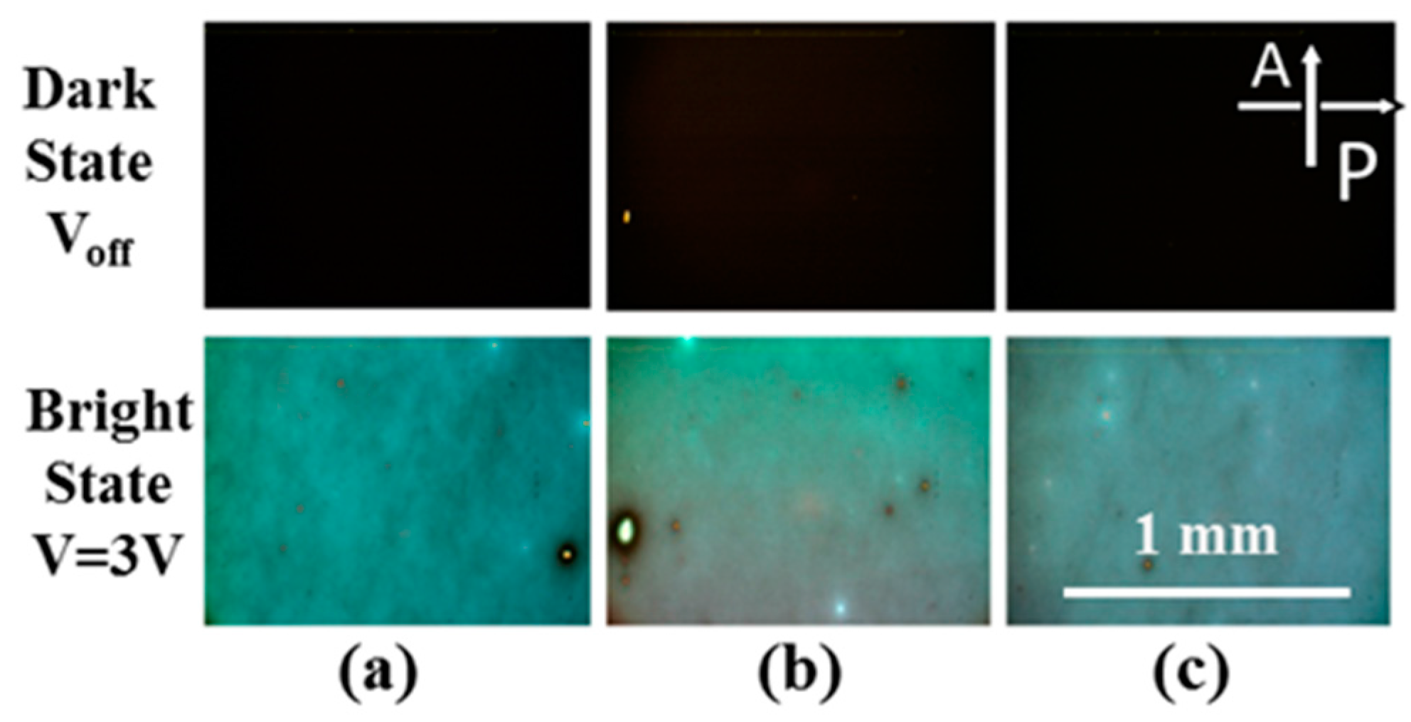
The photographs of the LC cells observed with a POM are shown in Figure 5 and Figure 6, which show the POSS alignment films prepared by Process I and Process II, respectively. Most LC cells, except for those of the POSS A film prepared by Process I, exhibited a good dark image (homeotropic alignment) in the voltage-off state. It was also observed that the LC cells can improve the dark state with the melting treatment of Process II, as seen by comparing the results shown in Figure 5b,c with results shown in Figure 6b,c. The LC cell with the POSS A film also becomes homeotropically aligned after the melting treatment as shown in Figure 6a. The semi-empirical rule called Friedel–Creagh–Kmetz (FCK) rule can be used to partially explain the mechanism of POSS-induced homeotropic alignment [22]. The FCK rule states that
  • γS < γLC—homeotropic alignment
  • γS > γLC—homogenous alignment
where γS describes the surface tension of the solid alignment film, and γLC is the surface tension of the LC. The LC molecules prefer to align perpendicularly to the solid film when the surface energy of the film is relatively low and the inter-molecular interaction of LC molecules is stronger than the interaction across the interface. The FCK rule has been widely supported by experimental data [22,23]. The contact angles and the calculated surface energy of the various POSS films, ITO glass substrates, and the commercial homeotropic (AL60101, JSR Corp. Tokyo, Japan) and homogeneous PI (AL-58, Daily Polymer Corp. Kaohsiung, Taiwan) films are summarized in Table 3. The alignment properties and FCK rule satisfaction of POSS films are also indicated in Table 3. As shown in Table 3, some of the POSS alignment films have surface energy values that are similar to those of the homeotropic PI and surface energies that are lower than those of the homogenous PI, as is expected in light of the FCK rule. The POSS films with homeotropic alignment fabricated by Process I, POSS B and POSS C, have surface energies similar to those of the homogeneous PI film, which cannot be explained by the FCK rule. The alignment of LC is known to be influenced by LC elastic constants and the surface morphology of the alignment films. A nematic liquid crystal that was vertically aligned on an anodic porous alumina (Al2O3) film has been reported [24,25] although it showed a higher surface energy compared with a homogenous PI [24]. The authors believed that, even if the LC director may prefer to align parallel to the surface of porous alumina films according to the FCK rule, the LCs of the bulk align homeotropically due to the smaller distortion energy of the vertical orientation, as opposed to the parallel orientation, with respect to the films, [24]. As shown in Figure 3 and Figure 4, the clusters of the POSS films may have an influence on the LC molecules that is similar to that of the porous alumina films. The influence of the homeotropically aligned nematic LC on the POSS films can then be expected by the same mechanism.
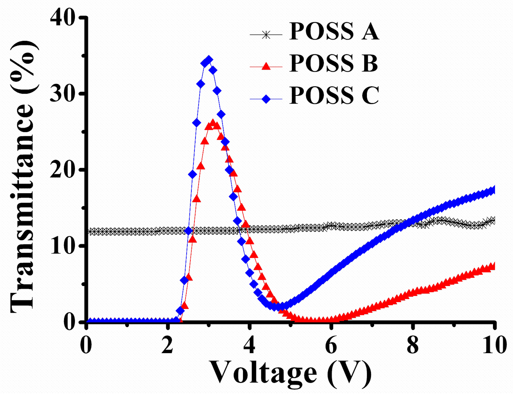
The voltage-dependent transmittance properties of LC cells with POSS films fabricated by Process I and Process II are shown in Figure 7 and Figure 8, respectively. The threshold voltage of each POSS-induced homeotropic alignment LC cell is close to 2.2 V, which agrees with the theoretical value [26]. LC molecules are aligned with the electric field, and the disclination lines are generated due to non-buffed alignment films, as the voltage is greater than the threshold voltage as shown in Figure 5. The transmittance values of LC cells fabricated by Process I reach about 30%, as shown in Figure 7. However, the transmittance of LC cells fabricated by Process II can reach ~70% as shown in Figure 8 although LC cells have not been treated with the rubbing process. No disclination lines are observed in those LC cell as shown in Figure 6. The improvement in LC alignment after melting treatment may be explained by the change in the surface roughness of the POSS films, which influences the interaction between the anisotropic elastic properties of LC and the morphology of the POSS alignment layer. The mechanism of the observed rubbing-like alignment for the POSS films with the melting treatment is still an open question and deserves further study in the future.
The alignment properties of POSS alignment films are also influenced by the pretilt angle and the anchoring energy. The pretilt angle and the polar anchoring energy of POSS alignment films with the melting treatment of Process II are summarized in Table 4. The pretilt angle is around 89°, and the polar anchoring energy density is about 1.3 × 10⁻⁴ J/m2, regardless of the types of POSS nanomaterials. Kumar et al. have found that the anisotropy in the surface morphology of an alignment film on a submicron length scale plays a defining role in determining the LC alignment direction, and the anchoring energy primarily depends on chemical interactions between the LC and the alignment layer [27]. Our results shown in Table 4 may suggest that a similar value of the polar anchoring energy measured with the different POSS films may be due to their identical cage structures interacting with LC molecules.

4. Conclusions

By using POSS nanomaterials with various functional groups as LC alignment films, we successfully demonstrated the homeotropic alignment of LC cells. The dark states and the transmittance of bright states of LC cells were improved after the melting treatment of POSS films. The POSS films showed similar alignment properties, as they all had identical cage structures. The proposed POSS alignment films are also suitable for the future development of flexible LCDs using plastic substrates requiring a low temperature process.

Acknowledgments

We thank Andy Ying-Guey Fuh and Ko-Ting Cheng of National Cheng Kung University for their support of AFM measurements and Shug-June Hwang of National United University and Yi-Hsin Lin of National Chiao Tung University for their helpful discussions. We also thank the anonymous reviewers for their constructive comments and English editing. This work was supported by the Ministry of Science and Technology of Taiwan under grants: NSC 98-2112-M-009-020-MY2, NSC 100-2112-M-009-014-MY3, and MOST 103-2112-M-009-013-MY3.

Author Contributions

C.-W. Huang performed the experiments and analyzed the data. S.-C. Jeng conceived and designed the experiments and wrote the manuscript.

Conflicts of Interest

The authors declare no conflict of interest.

References

  1. Qi, H.; Hegmann, T. Impact of nanoscale particles and carbon nanotubes on current and future generations of liquid crystal displays. J. Mater. Chem. 2008, 18, 3288–3294. [Google Scholar]
  2. Jeng, S.-C.; Kuo, C.-W.; Wang, H.-L.; Liao, C.-C. Nanoparticles-induced vertical alignment in liquid crystal cell. Appl. Phys. Lett. 2007, 91, 061112. [Google Scholar]
  3. Hwang, S.-J.; Jeng, S.-C.; Yang, C.-Y.; Kuo, C.-W.; Liao, C.-C. Characteristics of nanoparticle-doped homeotropic liquid crystal devices. J Phys. D 2009, 42, 025102. [Google Scholar]
  4. Teng, W.-Y.; Jeng, S.-C.; Ding, J.-M.; Kuo, C.-W.; Chin, W.-K. Flexible homeotropic liquid crystal displays using low-glass-transition-temperature poly(ethylene terephthalate) substrates. Jpn. J. Appl. Phys. 2010, 49, 010205. [Google Scholar]
  5. Hwang, S.-J.; Jeng, S.-C.; Hsieh, I.-M. Nanoparticle-doped polyimide for controlling the pretilt angle of liquid crystals devices. Opt. Express 2010, 18, 16507–16512. [Google Scholar]
  6. Kim, D.H.; Kwon, D.W.; Gim, H.Y.; Jeong, K.U.; Lee, S.H.; Jeong, Y.H.; Ryu, J.J.; Kim, K.H. Polymer-stabilized pretilt angle on the surface of nanoparticle-induced vertical-alignment surface for multi-domain vertical-alignment liquid-crystal display. J. SID 2011, 19, 417–422. [Google Scholar]
  7. Chen, W.-Z.; Tsai, Y.-T.; Lin, T.-H. Single-cell-gap transflective liquid-crystal display based on photo- and nanoparticle-induced alignment effects. Opt. Lett. 2009, 34, 2545–2547. [Google Scholar]
  8. Fuh, A.Y.-G.; Huang, C.-Y.; Liu, C.-K.; Chen, Y.-D.; Cheng, K.-T. Dual Liquid crystal alignment configuration based on nanoparticle-doped polymer films. Opt. Express 2011, 19, 11825–11831. [Google Scholar]
  9. Baney, R.H.; Itoh, M.; Sakakibara, A.; Suzuki, T. Silsesquioxanes. Chem. Rev. 1995, 95, 1409–1430. [Google Scholar]
  10. Leu, C.M.; Chang, Y.T.; Wei, K.H. Polyimide-side-chain tethered polyhedral oligomeric silsesquioxane nanocomposites for low-dielectric film applications. Chem. Mater. 2003, 15, 3721–3727. [Google Scholar]
  11. Xiao, S.; Nguyen, M.; Gong, X.; Gao, Y.; Wu, H.; Moses, D.; Heeger, A.J. Stabilization of semiconducting polymers with silsesquioxane. Adv. Funct. Mater. 2003, 13, 25–29. [Google Scholar]
  12. Wang, Z.; Li, Y.; Dong, X.-H.; Yu, X.; Guo, K.; Su, H.; Yue, K.; Wesdemiotis, C.; Cheng, S.Z.D.; Zhang, W.-B. Giant gemini surfactants based on polystyrene–hydrophilic polyhedral oligomeric silsesquioxane shape amphiphiles: sequential “click” chemistry and solution self-assembly. Chem. Sci. 2013, 4, 1345–1352. [Google Scholar]
  13. Kim, D.-Y.; Kim, S.; Lee, S.-A.; Choi, Y.-E.; Yoon, W.-J.; Kuo, S.-W.; Hsu, C.-H.; Huang, M.; Lee, S.H.; Jeong, K.-U. Asymmetric organic−inorganic hybrid giant molecule: cyanobiphenyl monosubstituted polyhedral oligomeric silsesquioxane nanoparticles for vertical alignment of liquid crystals. J. Phys. Chem. C 2014, 118, 6300–6306. [Google Scholar]
  14. Tanaka, K.; Ishiguro, F.; Jeon, J.-H.; Hiraoka, T.; Chujo, Y. POSS ionic liquid crystals. NPG Asia Mater. 2015, 7, e174. [Google Scholar]
  15. Li, Y.; Dong, X.-H.; Zou, Y.; Wang, Z.; Yue, K.; Huang, M.; Liu, H.; Feng, X.; Lin, Z.; Zhang, W.; et al. Polyhedral oligomeric silsesquioxane meets “click” chemistry: Rational design and facile preparation of functional hybrid materials. Polymer 2017, 125, 303–329. [Google Scholar]
  16. Tanaka, K.; Kozuka, H.; Ueda, K.; Jeon, J.-H.; Chujo, Y. POSS-based molecular fillers for simultaneously enhancing thermal and viscoelasticity of poly(methyl methacrylate) films. Mater. Lett. 2017, 203, 62–67. [Google Scholar]
  17. Sigma-Aldrich Corp. Available online: https://www.sigmaaldrich.com/ (accessed on 30 May 2017).
  18. Owens, D.K.; Wendt, R.C. Estimation of the surface free energy of polymers. J. Appl. Polym. Sci. 1969, 13, 1741–1747. [Google Scholar]
  19. Chen, K.-H.; Chang, W.-Y.; Chen, J.-H. Measurement of the pretilt angle and the cell gap of nematic liquid crystal cells by heterodyne interferometry. Opt. Express 2009, 17, 14143–14149. [Google Scholar]
  20. Nastishin, Y.A.; Polak, R.D.; Shiyanovskii, S.V.; Bodnar, V.H.; Lavrentovich, O.D. Nematic polar anchoring strength measured by electric field techniques. J. Appl. Phys. 1999, 86, 4199–4213. [Google Scholar]
  21. Hwang, S.J. Precise optical retardation measurement of nematic liquid crystal display using the phase-sensitive technique. J. Display Technol. 2005, 1, 77–81. [Google Scholar]
  22. Cognard, J. Alignment of nematic liquid crystals and their mixtures. Mol. Cryst. Liq. Cryst. Suppl. 1982, 1, 6. [Google Scholar]
  23. Geary, J.M.; Goodby, J.W.; Kmetz, A.R.; Patel, J.S. The mechanism of polymer alignment of liquid-crystal materials. J. Appl. Phys. 1987, 62, 4100–4108. [Google Scholar]
  24. Maeda, T.; Hiroshima, K. Vertically Aligned Nematic Liquid Crystal on Anodic Porous Alumina. Jpn. J. Appl. Phys. 2004, 43, L1004. [Google Scholar]
  25. Tang, T.-T.; Kuo, C.-Y.; Pan, R.-P.; Shieh, J.-M.; Pan, C.-L. Strong Vertical Alignment of Liquid Crystal on Porous Anodic Aluminum Oxide Film. J. Display Technol. 2009, 5, 350–354. [Google Scholar]
  26. Lueder, E. Liquid Crystal Displays: Addressing Schemes and Electro-Optical Effects; John Wiley & Sons: Hoboken, NJ, USA, 2001. [Google Scholar]
  27. Kumar, S.; Kim, J.-H.; Shi, Y. What aligns liquid crystals on solid substrates? The role of surface roughness anisotropy. Phys. Rev. Lett. 2005, 94, 077803. [Google Scholar]
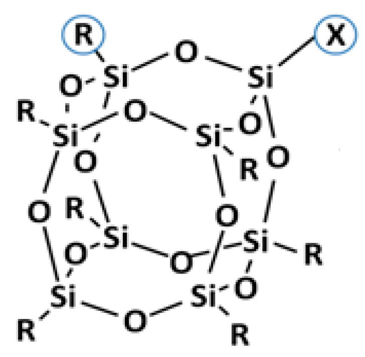
Figure 1. A schematic structure of a polyhedral oligomeric silsesquioxane (POSS) nanoparticle, where R is the nonreactive functional group and X is the reactive functional group [9].
Colloids 02 00009 g001
Figure 2. The structures of POSS nanomaterials used in this work. (a) Aminoethyl-aminopropylisobutyl-POSS (POSS A), (b) trans-cyclohexanediolisobutyl-POSS (POSS B), and (c) 1,2-propanediolisobutyl-POSS (POSS C) [17].
Colloids 02 00009 g002
Figure 3. The morphology of the POSS films observed via AFM by using Process I. (a) POSS A, (b) POSS B, and (c) POSS C.
Colloids 02 00009 g003
Figure 4. The morphology of the POSS films observed via AFM by using Process II. (a) POSS A, (b) POSS B, and (c) POSS C.
Colloids 02 00009 g004
Figure 5. The photographs of LC cells observed with a polarizing optical microscope (POM) prepared by Process I. (a) POSS A, (b) POSS B, and (c) POSS C.
Colloids 02 00009 g005
Figure 6. The photographs of LC cells observed with a POM for POSS films prepared by Process II. (a) POSS A, (b) POSS B, and (c) POSS C.
Colloids 02 00009 g006
Figure 7. The voltage-dependent transmittance of LC cells with POSS alignment films by using Process I.
Colloids 02 00009 g007
Figure 8. The voltage-dependent transmittance of LC cells with POSS alignment films by using Process II.
Colloids 02 00009 g008
Table 1. The properties of the POSS nanomaterials [17].
MaterialPOSS APOSS BPOSS C
Chemical FormulaC33H76N2O12Si8C36H78O14Si8C34H76O15Si8
Melting Point108–117 °C121–127 °C117–123 °C
Table 2. The surface roughness of POSS films.
Surface Roughness (nm)Process IProcess II
POSS A10.11.9
POSS B23.91.7
POSS C33.32.2
Table 3. The contact angle a and surface energy of various solid films.
Process MaterialProcess I (Coating)Process II (Melting)
H2OCH2I2SA bVA cFCKH2OCH2I2SA bVA cFCK
POSS A102.459.629.1NoNo107.359.229.0YesYes
POSS B73.547.142.7YesNo103.149.934.3YesYes
POSS C66.147.446.2YesNo105.959.628.8YesYes
H-PI d80.033.745.9
V-PI e100.248.035.4
ITO25.133.372.3
a Unit of contact angle: degree. b SA: Surface energy (mN/m). c VA: Homeotropic alignment. d H-PI: Homogenous PI. e V-PI: Homeotropic PI.
Table 4. The pretilt angle and polar anchoring energy (PAE) of POSS films.
MaterialPOSS APOSS BPOSS C
Pretilt angle89.7° ± 0.1°89.7° ± 0.2°89.4° ± 0.1°
PAE (×104 J/m2)1.3 ± 0.31.4 ± 0.31.2 ± 0.2