Article

Fatigue Behaviors of High-Speed Track Slabs Reinforced by GFRP Composite Rebar: Full-Scale Experimental Verification

Department of Civil Systems Engineering, Gyeongkuk National University, Andong-Si 36729, Republic of Korea
J. Compos. Sci. 2025, 9(11), 597; https://doi.org/10.3390/jcs9110597
Submission received: 30 August 2025 / Revised: 17 October 2025 / Accepted: 24 October 2025 / Published: 2 November 2025
(This article belongs to the Special Issue Research on Fatigue and Failure Mechanisms of Composites)

Abstract

This study deals with the fatigue behavior of on-site-installation-type track slabs subject to cycling train load developed by applying glass-fiber-reinforced polymer (GFRP) reinforcing bars. Concrete track slabs have the most severe deterioration in track circuit characteristic values due to the conduction influence of existing steel bars. Therefore, a track slab applying an insulator and lightweight GFRP reinforcement by replacing the existing steel bar was proposed from a design perspective. In order to present the validity of the proposed method, a full-size specimen was manufactured and a fatigue performance test was performed, and the results were compared with the test specimen applied with steel bars. From the results of various fatigue behaviors, it was found that displacement variations during cyclic loading remained within 1 mm, and load variations were within 10 kN, indicating excellent stability under accumulated fatigue cycles. This study analyzed the macro-level structural behavior of GFRP-reinforced concrete track slabs under fatigue loading. Future research will further investigate micro-level bond interactions between the reinforcement and concrete to validate long-term performance.

1. Introduction

Concrete track slabs in high-speed railway systems are subjected to extremely high numbers of load cycles and harsh environmental conditions throughout their service life. Conventional steel reinforcement, although providing ductility and well-established design methodologies, is prone to corrosion, chloride attack, and stray-current degradation in electrified rail systems. These durability problems shorten the service life of slabs and increase long-term maintenance costs, undermining the reliability of railway infrastructure. To address these challenges, the use of GFRP reinforcement has been proposed as a promising alternative. GFRP bars provide high tensile strength, corrosion resistance, and electrical insulation, which are particularly advantageous in track slab applications where structural durability and electrical neutrality are equally important. However, the linear–elastic brittle rupture of GFRP and its relatively lower modulus of elasticity compared to steel demand a shift in design philosophy. Instead of relying on ductility, the structural safety of GFRP-reinforced slabs must be ensured through service-level stress control and explicit verification against fatigue and creep-rupture under sustained and cyclic loads [1,2,3].
In recent years, both international codes and experimental studies have advanced the understanding of GFRP behavior under fatigue and sustained loading. The AASHTO Guide Specifications [1] established a framework in which creep rupture and fatigue limit states are mandatory checks, requiring that reinforcement stresses remain below conservative fractions of the design tensile strength at service load levels. Likewise, the CSA S6-19 Canadian Highway Bridge Design Code [2] and CSA S807-19 Specification [3] for Fiber-Reinforced Polymers reinforced this stress-limited design philosophy by stipulating durability factors and explicit fatigue verification for GFRP-reinforced bridges. The adoption of ACI 440.11-22 [4] for structural concrete further illustrates the institutional recognition of GFRP as a mainstream reinforcement material, though its emphasis remains primarily on sustained stress and serviceability rather than fatigue.
There are very few existing studies on the application of GFRP reinforcement to concrete track slabs in a railway system. Therefore, this study analyzed research trends focusing on the fatigue behavior of similar flexural members such as beams and slabs that incorporate GFRP reinforcement. Large-scale fatigue tests have shown that GFRP-reinforced beams and slabs can sustain millions of cycles without significant stiffness degradation, demonstrating that the material is capable of withstanding railway-type repeated load environments [5]. Investigations into bond behavior under cyclic loading have further revealed that GFRP–concrete bond performance remains stable even after extensive load repetitions, providing confidence that service-level stresses can be reliably transferred across the reinforcement–concrete interface [6]. In a broader context, Ebrahimzadeh et al. [7] provided a comprehensive review of GFRP-reinforced concrete segmental decks, highlighting that fatigue remains a governing factor for long-term serviceability and structural safety, particularly in bridge and marine applications. Ali et al. [8] studied static and fatigue behavior of concrete bridge deck slabs reinforced with BFRP and steel bars. At the material level, Alajarmeh et al. [9] investigated unidirectional pultruded GFRP composites and showed how high-fiber volume fractions influence durability under cyclic loading, offering insights into the fundamental fatigue mechanisms of GFRP composites. Comparative full-scale tests between steel- and GFRP-reinforced slab tracks provide compelling evidence of GFRP’s effectiveness. Results indicate that GFRP reinforcement can extend the fatigue life of track slabs by more than 30% relative to conventional steel reinforcement under identical axle load protocols, confirming that GFRP not only improves durability but also enhances overall fatigue resistance in railway applications [10].
This study develops and validates a fatigue design methodology for GFRP-reinforced concrete track slabs that aligns with the limit-state philosophy of international codes. The approach employs cracked-section elastic analysis to calculate reinforcement stresses under sustained and cyclic loading. These stresses are then checked against creep rupture and fatigue thresholds defined in AASHTO [1] and CSA S6/S807 [2,3], ensuring compliance with established design requirements. Beyond reinforcement stresses, the methodology incorporates serviceability checks, including crack-width and deflection limits, which are particularly important in slab tracks due to their influence on ride comfort and fastening system durability. To validate the design framework, this study integrates analytical design with full-scale experimental fatigue testing, directly comparing GFRP-reinforced slabs to conventional steel-reinforced specimens.
The objectives of the research are therefore threefold: (1) to establish a transparent and reproducible fatigue design framework for GFRP-reinforced track slabs based on code provisions and experimental evidence; (2) to demonstrate through large-scale testing that GFRP reinforcement can satisfy both fatigue resistance and serviceability requirements under railway-type repeated loading; and (3) to contribute to the refinement of international design codes by providing new insights into the fatigue performance of slab track systems.

2. Fatigue Design of GFRP Reinforcement

2.1. Governing Limit States

The fatigue behavior of GFRP reinforcement differs substantially from that of conventional steel reinforcement due to its linear–elastic stress–strain relationship up to brittle rupture. Design codes therefore adopt stress-based limit states, which restrict reinforcement stresses under sustained and cyclic loads to conservative fractions of the design tensile strength.
Creep rupture refers to the long-term failure of GFRP reinforcement under sustained stresses, which can occur at stress levels much lower than the short-term tensile capacity. The governing criterion in AASHTO (2018) is expressed as
f f , f s C c f f d
where f f , f s means sustained tensile stress in reinforcement under Service I load combinations (live load factor reduced to 0.2), and f f , f s is design tensile strength of GFRP, obtained from
f f d = C E f * f u
where f * f u means guaranteed tensile strength, and C E and C C denote environmental reduction factor and creep rupture reduction factor (default = 0.30 in AASHTO), respectively.
This limit state ensures that reinforcement will not fail prematurely under the combined effects of dead load, sustained live load, and environmental degradation.
Cyclic loading conditions are particularly relevant in bridge decks and railway slabs. Unlike steel, GFRP does not exhibit an endurance limit; fatigue resistance is stress-controlled. AASHTO specifies the following requirement:
f f , f C f f f d
where f f , f means maximum tensile stress in reinforcement under Service I + Fatigue I load combination, and C E is a fatigue reduction factor (default = 0.25). The two limit states—creep rupture and fatigue—act as complementary checks. Sustained stress governs long-term durability, while cyclic stress governs service environments with frequent loading. For highway bridges, bottom reinforcement is often governed by creep rupture, whereas top reinforcement near wheel loads is governed by fatigue limit state (FLS) Together, these provisions prevent both premature static rupture and cycle-induced degradation.

2.2. Stress Calculation Procedure and Design Methodology

Fatigue verification requires accurate estimation of stresses in GFRP reinforcement. Since GFRP does not yield, stresses are evaluated using linear–elastic cracked section analysis, ensuring compatibility between reinforcement and concrete strains. The reinforcement stress is expressed as
f f = n f · d · 1 k I c r M
where n f means the modular ratio of GFRP to concrete, and d, k, I c r and M denote effective depth of reinforcement, neutral axis ratio, cracked transformed moment of inertia and bending moment from service load combination, respectively.
Next, the neutral axis location is determined by enforcing force equilibrium:
A f E f d k h = 0.5 k h E c
where A f , h, and b mean reinforcement area, section depth, and section width, respectively. Iterative solutions yield k, which defines the cracked section properties.
The fatigue design of GFRP reinforcement requires a systematic sequence of calculations to evaluate stresses accurately and verify compliance with the governing limit states. The procedure begins with the transformation of the reinforcement area into an equivalent concrete area using the modular ratio n f . This transformation allows the cracked section analysis to incorporate the difference in stiffness between GFRP and concrete.
Once the equivalent section is established, the neutral axis depth is determined by satisfying the condition of internal force equilibrium between the tensile force carried by the GFRP reinforcement and the compressive force carried by the concrete in compression. This iterative calculation yields the neutral axis ratio k, which defines the stress distribution within the cracked section. With the neutral axis location known, the cracked moment of inertia of the transformed section, I c r , is then computed. This property is essential for evaluating the flexural stiffness of the cracked member and forms the basis for reinforcement stress calculations. Subsequently, the tensile stress in the GFRP reinforcement is obtained by applying the bending moment corresponding to the relevant service load combinations. For sustained load cases, the calculated stress f f , s must be checked against the creep rupture limit, ensuring that long-term stress levels remain below 30% of the design tensile strength. For fatigue load cases, the reinforcement stress f f , f is calculated under the Service I + Fatigue I combination and verified against the fatigue limit of 25% of the design tensile strength. This stepwise procedure, while straightforward in formulation, provides a rigorous and conservative basis for fatigue design. By explicitly linking material properties, section geometry, and applied loads, it ensures that GFRP reinforcement remains within safe stress thresholds under both sustained and cyclic demands.

3. Structural Design of a Full-Size Specimen

The structural design of the cam plate and concrete slab layer was carried out using GFRP reinforcement, based on the theoretical analysis of flexural and fatigue behaviors. The TCL (track concrete layer) was designed with an average thickness of 356 mm and width of 1000 mm, while the PCL (Protection Concrete Layer) measured 150 mm in thickness and 1000 mm in width. For the bridge application, the span length was selected to maximize impact effects under train loading. Longitudinal loads included start/braking forces transferred along the rail axis, modeled with a concentrated train load of 1.8 m and an equivalent line (EL) load acting horizontally at a height of 1.5 m. In addition, meandering loads of 100 kN distributed over 3.0 m, centrifugal loads, wind actions, and rail temperature effects were considered for both straight and curved track conditions. Constrained actions due to temperature change and shrinkage were incorporated according to DIN 1045-1 [11].
For slab design under constraint forces, the cam plate restrains the slab’s free contraction, inducing tensile stresses that must be resisted by GFRP reinforcement. The required reinforcement ratio was determined not only to satisfy structural demand but also to control crack widths under service conditions. Although tensile force was assumed to be distributed across the full width of the slab, stress concentration at the cam plate interface was recognized [12]. Thus, reinforcement in this region was conservatively designed to carry 50% of the total tensile force. If the reinforcement demand fell below the minimum requirement, an additional one-third was provided to ensure structural safety. Since the effective tensile strength of GFRP rebars varies with diameter, the reinforcement layout was adjusted such that the provided capacity closely matched the theoretical requirement.
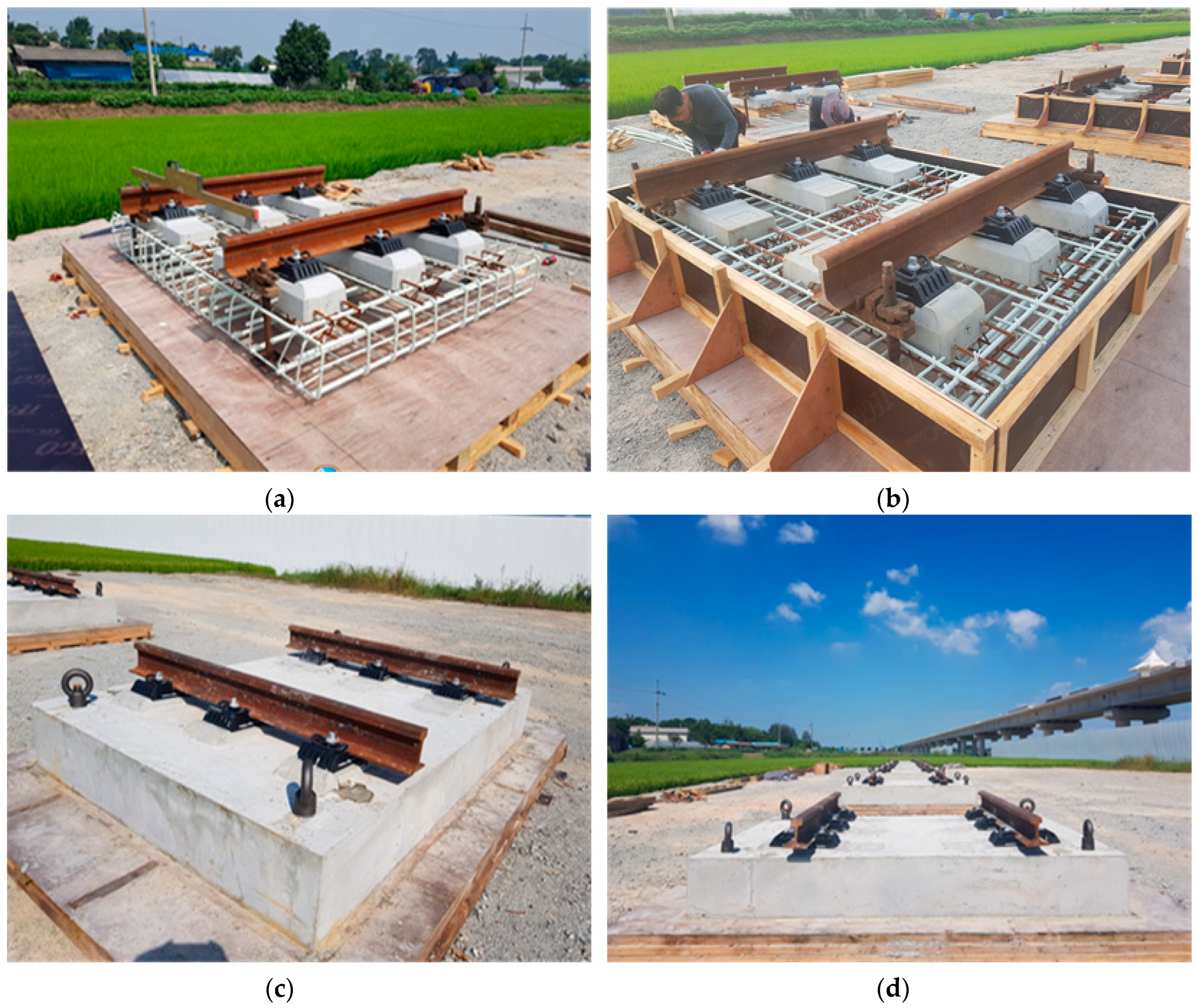
The TCL does not directly sustain vertical train loads, and its governing sectional force corresponds to longitudinal deflection effects. Crack width calculations were performed according to ACI 440.1R-06 [13], with a limiting value of 0.5 mm applied at the longitudinal bottom surface. This criterion ensured both serviceability and long-term durability of the slab system. The final reinforcement arrangement proposed a layout of 1.9 m in the longitudinal direction for full-scale fatigue specimen testing, as illustrated in Figure 1. By adopting this reinforcement strategy, the design not only satisfied structural performance requirements under combined load effects but also ensured adequate crack control and durability, validating the applicability of GFRP reinforcement in high-speed railway slab systems. Figure 2 shows manufacturing process of track concrete slab using GFRP rebar.

4. Full-Scale Experiment

Experimental Setup

In order to investigate the fatigue resistance and long-term behavior of reinforced concrete members, fatigue loading tests were conducted on beam specimens reinforced with either traditional steel rebars or GFRP bars. According to BS EN 13230-4 [14], the fatigue test for concrete track slabs is specified as frequency between 2 Hz and 10 Hz (identical frequency maintained during the duration of the test) for 2 million cycles. In this study, the fatigue test was conducted in compliance with this specification, and the loading frequency was set to 3 Hz considering the conditions of the testing equipment. Furthermore, although the standard specifies 2 million cycles, the number of loading cycles was increased to 3 million to enhance the reliability of the test results. Then, in this study, the full-scale specimens were fabricated outdoors and were exposed to environmental conditions (temperature, humidity, etc.) for more than three months. Since no concrete cracking was observed after curing, such environmental effects were not considered in the subsequent indoor fatigue tests. In this study, full-scale specimens identical to the actual structures were fabricated and tested in accordance with the BS EN 13230-4 [14] testing standard. The standard for slab testing does not specify the required number of specimens. Since this research deals with large, full-scale specimens rather than small-scale models used for probabilistic statistical analysis, one specimen was fabricated for each case and subjected to long-term fatigue testing.
Figure 3 and Table 1 provide detailed information on the loading protocol adopted for the long-term fatigue tests. As summarized in Table 1, the design axle load was 220 kN, in accordance with high-speed railway design standards [15]. The fatigue load was calculated by applying an impact factor (i) to the design axle load, resulting in a wheel load of 132 kN (i.e., 220/2 × 1.2). As illustrated in Figure 3, loading was first increased to the design load level (Fd), followed by cyclic loading between the minimum load (Fmin) and the reference load (F0). As mentioned earlier, the fatigue test was carried out for a total of 3 million cycles with 3 Hz loading frequency, during which the maximum deflection and crack propagation of the specimen were monitored. Figure 4 shows an overview of the fatigue testing setup.
Figure 5 and Figure 6 present the results of the static loading test conducted prior to the fatigue test for the longitudinal specimen reinforced with steel or GFRP bars. The loading sequence was applied in the order of 0.0 kN → 264 kN → 352 kN → 264 kN → 10.0 kN. The displacement was measured using load cells (L/C) installed beneath the specimen supports. These load cells continuously recorded vertical movement during the loading process to evaluate deformation behavior. From this test, the L/C displacement, the time history of L/C load and displacement, and the load–displacement relationship for L/C were obtained. The load–displacement curves in Figure 5 show that both specimens exhibit a typical load increase followed by a plateau and gradual decrease, indicating nonlinear deformation behavior before unloading. The steel-reinforced specimen (a) demonstrates slightly higher load capacity and longer plateau duration, reflecting its ductile yielding response. In contrast, the GFRP-reinforced specimen (b) shows a steeper load–displacement path and faster unloading, consistent with the linear–elastic and brittle characteristics of GFRP reinforcement. Figure 6 illustrates that the GFRP-reinforced specimen exhibits higher load-carrying capacity and stiffness compared to the steel-reinforced specimen under identical displacement levels. However, the steel specimen shows a slightly larger residual deformation, reflecting its ductile behavior, while the GFRP specimen demonstrates a more elastic and recoverable response.
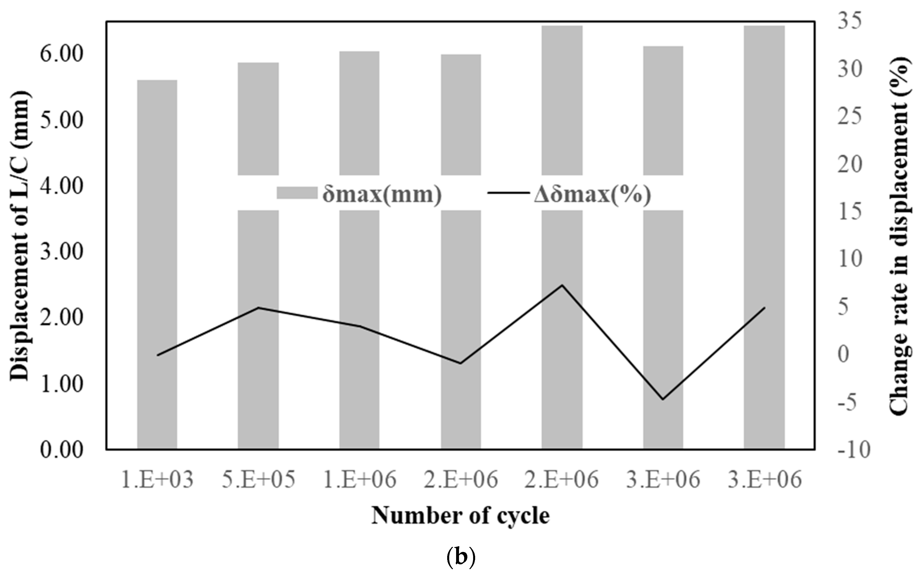
Figure 7 and Figure 8 compare the variations in L/C displacement and the trends in displacement change rate for GFRP- and steel-reinforced specimens under accumulated fatigue cycles (1 cycle: 10 kN → 264 kN → 10 kN). For both specimens, the displacement variation during repeated loading remained within 1 mm, indicating minimal change, and the rate of variation was found to decrease as the number of cycles accumulated. Figure 9 and Figure 10 shows comparison of the variations in L/C load and the trends in load change rate for GFRP- and steel-reinforced specimens under accumulated fatigue cycles. Similarly to the observations in Figure 8 and Figure 9, the load variation during repeated loading for both specimens remained within 10 kN, indicating minimal change, and the rate of variation decreased as the number of cycles increased. Figure 11 and Figure 12 present the variations in minimum and maximum L/C displacements and the corresponding change rates for GFRP- and steel-reinforced specimens under accumulated fatigue cycles. In Figure 11, the slight fluctuations in the increment rate suggest small elastic adjustments and microstructural accommodation during cyclic loading. Overall, no progressive increase in displacement of the steel reinforcement was observed up to 3 million cycles, confirming the long-term serviceability and deformation stability under repeated loading. In the case of the GFRP reinforcement (Figure 12), the small fluctuation in the increment rate reflects minor elastic adjustments rather than progressive degradation. Overall, the GFRP specimen maintained consistent stiffness and exhibited no significant increase in displacement, confirming its excellent fatigue resistance.
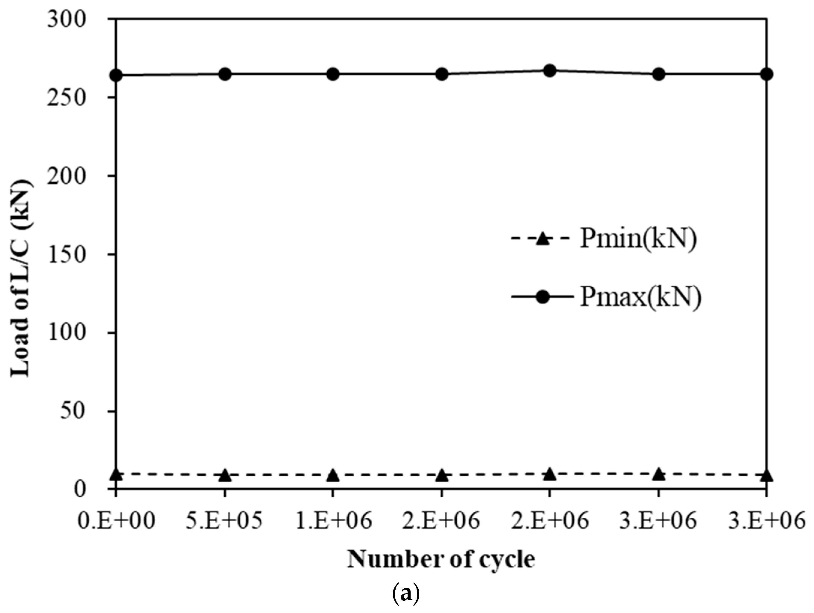
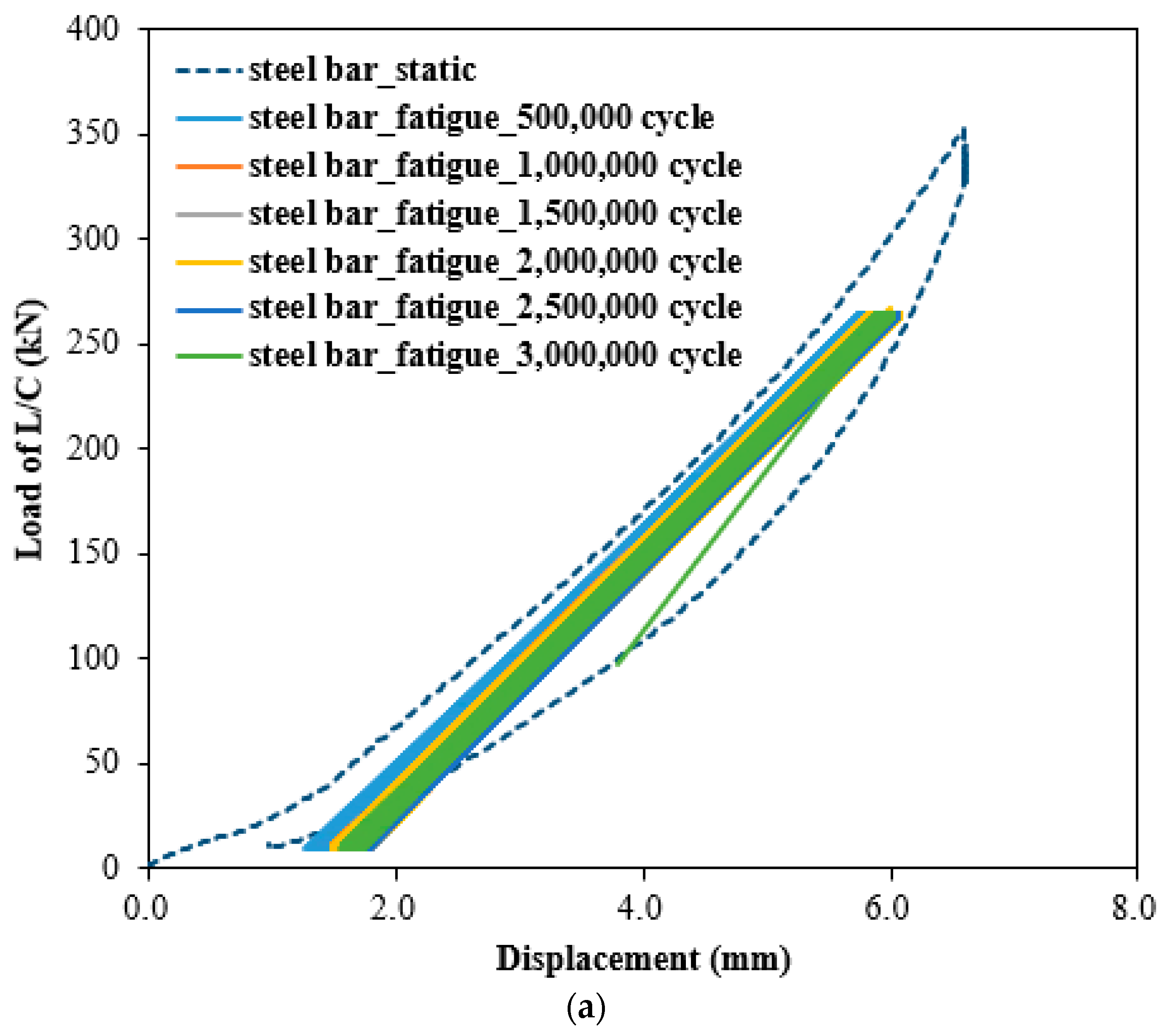
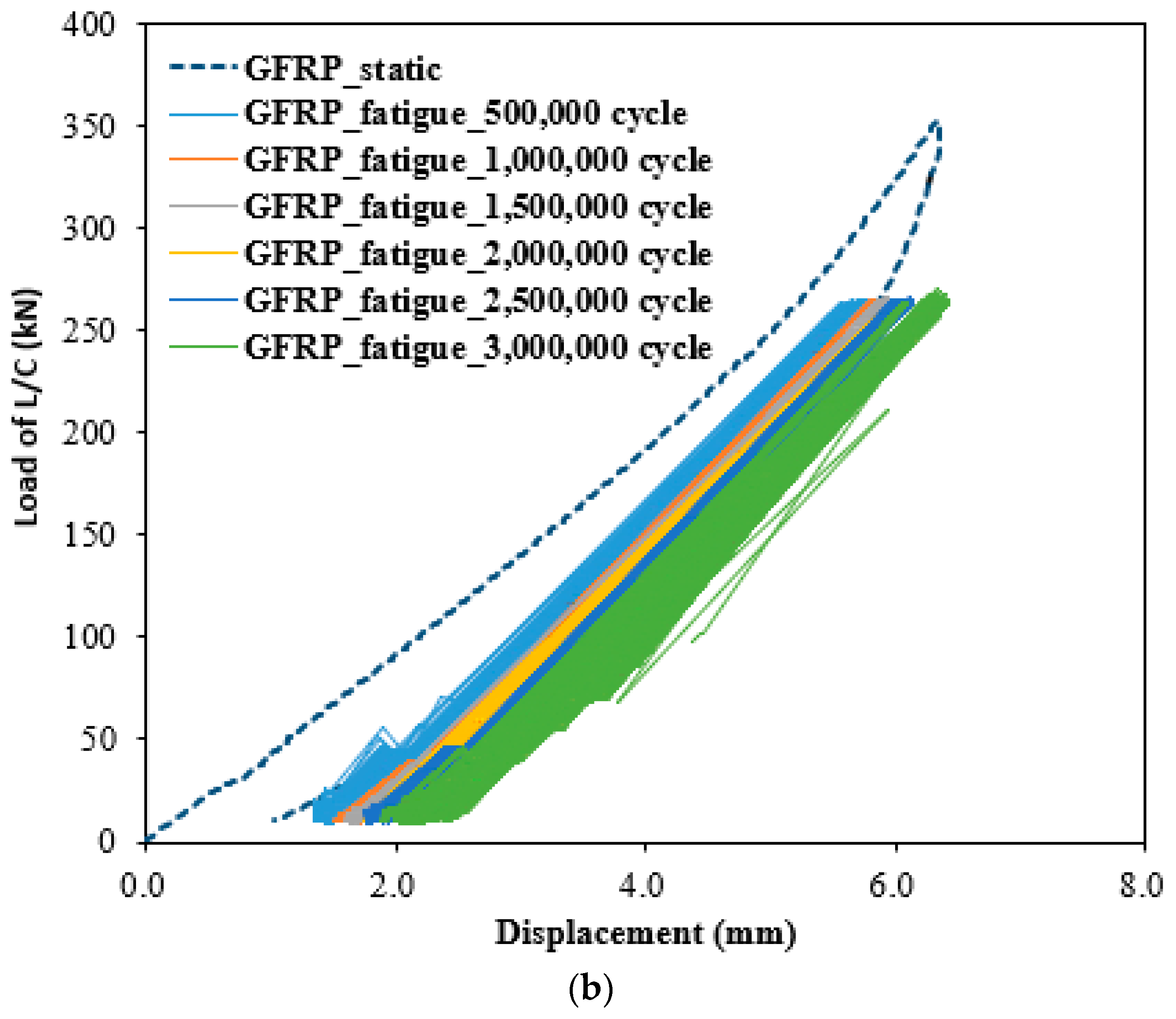
Figure 13 and Figure 14 present the L/C load–displacement responses of the two specimens under 1 to 3 million repeated loading cycles, as well as the variations in L/C displacement and L/C load with accumulated loading cycles. The results indicate that displacement increased slightly as the number of loading cycles progressed; however, the final displacement variation remained within 1 mm, indicating minimal change. Furthermore, while a slight increase in displacement was observed with cycle accumulation, the load variation was found to be negligible. Based on the experimental results, it can be concluded that the variation in load cell displacement with accumulated cycles was minimal, indicating the potential to ensure long-term serviceability. In addition, the small variation in load cell load with cycle accumulation suggests that dynamic structural stability and fatigue resistance can be adequately maintained.
Figure 15 shows the crack inspection results for each section of the GFRP-reinforced specimen after completion of the 3 million-cycle fatigue test. No cracks were observed following the fatigue test, indicating that the bond performance of the reinforcement was maintained even under dynamic repeated loading. A similar fatigue test was conducted on the steel-reinforced specimen, and comparable results to those of the GFRP-reinforced specimen were obtained. Based on the results of this study, since almost no displacement or cracking occurred after the completion of the fatigue loading, stiffness reduction and energy dissipation were not directly investigated but are expected to be negligible. GFRP reinforcement itself is brittle and has a lower elastic modulus, which could make it more susceptible to cracking under fatigue loading compared to steel reinforcement. However, the current fatigue design provisions for GFRP tend to be somewhat conservative, and the concrete used for track slabs is typically of high strength. Therefore, it is considered that within the range of fatigue loads applied in this study, the stress transfer was not sufficient to induce cracking.

5. Summary and Conclusions

This study investigates the fatigue behavior of GFRP-reinforced concrete track slabs subjected to high-speed train loads, with the aim of evaluating the long-term performance and serviceability of GFRP reinforcement in railway infrastructure. A full-scale specimen was manufactured, and fatigue tests were conducted over three million cycles to assess the fatigue resistance and structural behavior of GFRP-reinforced slabs in comparison to traditional steel-reinforced specimens. Within the limited scope of this study, this is the first attempt of its kind, and there are very few existing studies on this topic. We find the following key observations in designing GFRP-reinforced track structural system in long-term behaviors.
(1)
Both steel- and GFRP-reinforced specimens exhibited a typical nonlinear response characterized by a gradual load increase, plateau, and unloading phase. The steel-reinforced specimen showed slightly higher load capacity and a longer plateau, indicating ductile yielding, whereas the GFRP-reinforced specimen displayed a steeper load–displacement path and faster unloading, consistent with its linear–elastic and brittle characteristics. Under identical displacement levels, the GFRP specimen exhibited higher stiffness and load-carrying capacity, while the steel specimen showed slightly larger residual deformation due to its ductile nature.
(2)
For both materials, displacement variations during cyclic loading remained within 1 mm, and load variations were within 10 kN, indicating excellent stability under accumulated fatigue cycles. The fluctuation in displacement change rates decreased as the number of cycles increased, implying stabilization of internal stresses. The steel-reinforced specimen maintained stable deformation behavior without progressive displacement growth up to three million cycles. Similarly, the GFRP-reinforced specimen exhibited only minor elastic adjustments with no signs of stiffness degradation, confirming superior fatigue resistance.
(3)
Both steel- and GFRP-reinforced slabs maintained nearly identical load–displacement relationships across 1 to 3 million loading cycles, closely following the static curve. Displacement increased slightly with loading cycles; however, the total variation remained below 1 mm, signifying negligible deformation accumulation. The minimal change in load cell displacement and load with cycle accumulation indicates that dynamic structural stability and long-term serviceability can be effectively maintained under repeated loading. These findings verify that both reinforcement types provide sufficient stiffness retention and fatigue durability over extended service life.
(4)
No cracking was observed in the GFRP-reinforced specimen after the 3-million-cycle fatigue test, confirming that the bond between the GFRP bars and surrounding concrete was well maintained under dynamic loading. Similar behavior was observed in the steel-reinforced specimen. Based on these findings, a fatigue design methodology for GFRP-reinforced track slabs is proposed, harmonized with international standards. The methodology incorporates cracked-section elastic analysis for stress evaluation under sustained and cyclic loading, ensuring compliance with creep-rupture and fatigue limit states. Furthermore, serviceability criteria such as crack width and deflection limits are included to guarantee durability and safety. Overall, this study demonstrates that GFRP reinforcement offers a reliable, durable, and sustainable alternative to steel reinforcement for high-speed railway track slabs, contributing significantly to modern, long-life, low-maintenance infrastructure design.
The results of this study contribute to the ongoing efforts to refine the use of GFRP reinforcement in critical infrastructure, demonstrating that GFRP can serve as a durable, sustainable, and reliable alternative to steel reinforcement for high-speed railway track slabs. This research provides valuable insights into the performance and design considerations for GFRP-reinforced track slabs and encourages the broader adoption of GFRP as a sustainable solution in modern railway engineering. However, this study analyzed the macro-level structural behavior of GFRP-reinforced concrete track slabs subjected to fatigue loading. In future research, more comprehensive investigations with additional specimens will be required to examine the micro-level behavior in greater detail—such as the long-term bond interaction between the reinforcement and concrete under sustained loading—for further validation and comparison.

Funding

This research received no external funding.

Data Availability Statement

The original contributions presented in this study are included in the article. Further inquiries can be directed to the corresponding author.

Conflicts of Interest

The author declares no conflicts of interest.

References

  1. AASHTO. Guide Specifications for the Design of Concrete Bridge Decks Reinforced with GFRP Bars, 2nd ed.; American Association of State Highway and Transportation Officials: Washington, DC, USA, 2018. [Google Scholar]
  2. S6-19; Canadian Highway Bridge Design Code. Canadian Standards Association: Toronto, ON, Canada, 2019.
  3. S807-19; Specification for Fibre-Reinforced Polymers. Canadian Standards Association: Toronto, ON, Canada, 2019.
  4. ACI 440.11-22; Building Code Requirements for Structural Concrete Reinforced with Glass Fiber-Reinforced Polymer Bars. American Concrete Institute: Farmington Hills, MI, USA, 2022.
  5. Nagy, I.E.; Asadian, A.; Galal, K. Fatigue life and behaviour of ribbed GFRP reinforced concrete beams. Eng. Struct. 2024, 309, 117989. [Google Scholar] [CrossRef]
  6. Gao, K.; Wu, Z.; Li, Z.; Cai, C.; Zhang, L.; Xiao, S.; Hu, J. Fatigue bond behavior of glass fiber reinforced polymer bars with varying confinement levels. J. Build. Eng. 2025, 111, 113115. [Google Scholar] [CrossRef]
  7. Ebrahimzadeh, S.; Manalo, A.; Alajarmeh, O.; Sorbello, C.D.; Weerakoon, S.; Mohammed, A.; Hassanli, R.; Benmokrane, B. GFRP-reinforced concrete segmental decks for maritime infrastructures: Structural behaviour review. Sustain. Resilient Infrastruct. 2025, 1–32. [Google Scholar] [CrossRef]
  8. Ali, Y.M.S.; Wang, X.; Huawei, G.; Liu, S.; Da, L.; Wu, Z.; Moussa, A.M.A. Static and fatigue behavior of concrete bridge deck slabs reinforced with BFRP and steel bars. Structures 2024, 65, 106707. [Google Scholar] [CrossRef]
  9. Alajarmeh, O.; Manalo, A.; Ferdous, W.; Almasabha, G.; Tarawneh, A.; Awwad, K.E.; Safonov, A.; Zeng, X.; Schubel, P. Fatigue behavior of unidirectional fiber-reinforced pultruded composites with high volume fiber fraction. Fatigue Fract. Eng. Mater. Struct. 2023, 46, 2034–2048. [Google Scholar] [CrossRef]
  10. Toprak, M.A.; Güllü, A.; Özden, B.; Ölçer, B.; Durgun, Y.; Şahin, F.; Saruhan, H.; Yüksel, E. Fatigue behavior evaluation of two full-scale composite ballastless slab tracks incorporating steel and glass fiber rods. Constr. Build. Mater. 2025, 468, 140456. [Google Scholar] [CrossRef]
  11. DIN 1045-1:2008-08; Concrete, Reinforced and Prestressed Concrete Structures—Part 1: Design and Construction. Beuth Verlag: Berlin, Germany, 2008.
  12. Aly, M.H.F.; El-Naga, I.M.A.; Soliman, A.A.H.; Diab, M.A. Modelling of slab track systems for design purposes. J. Eng. Appl. Sci. 2023, 70, 115. [Google Scholar] [CrossRef]
  13. ACI 440.1R-06; Guide for the Design and Construction of Concrete Reinforced with FRP Bars. American Concrete Institute: Farmington Hills, MI, USA, 2006.
  14. BS EN 13230-4; Railway Applications—Track—Concrete Sleepers and Bearers. BSI Standards: London, UK, 2016.
  15. EN 1991-2; Eurocode 1—Actions on Structures, Part 2: Traffic Loads on Bridges. CEN: Brussels, Belgium, 2003.
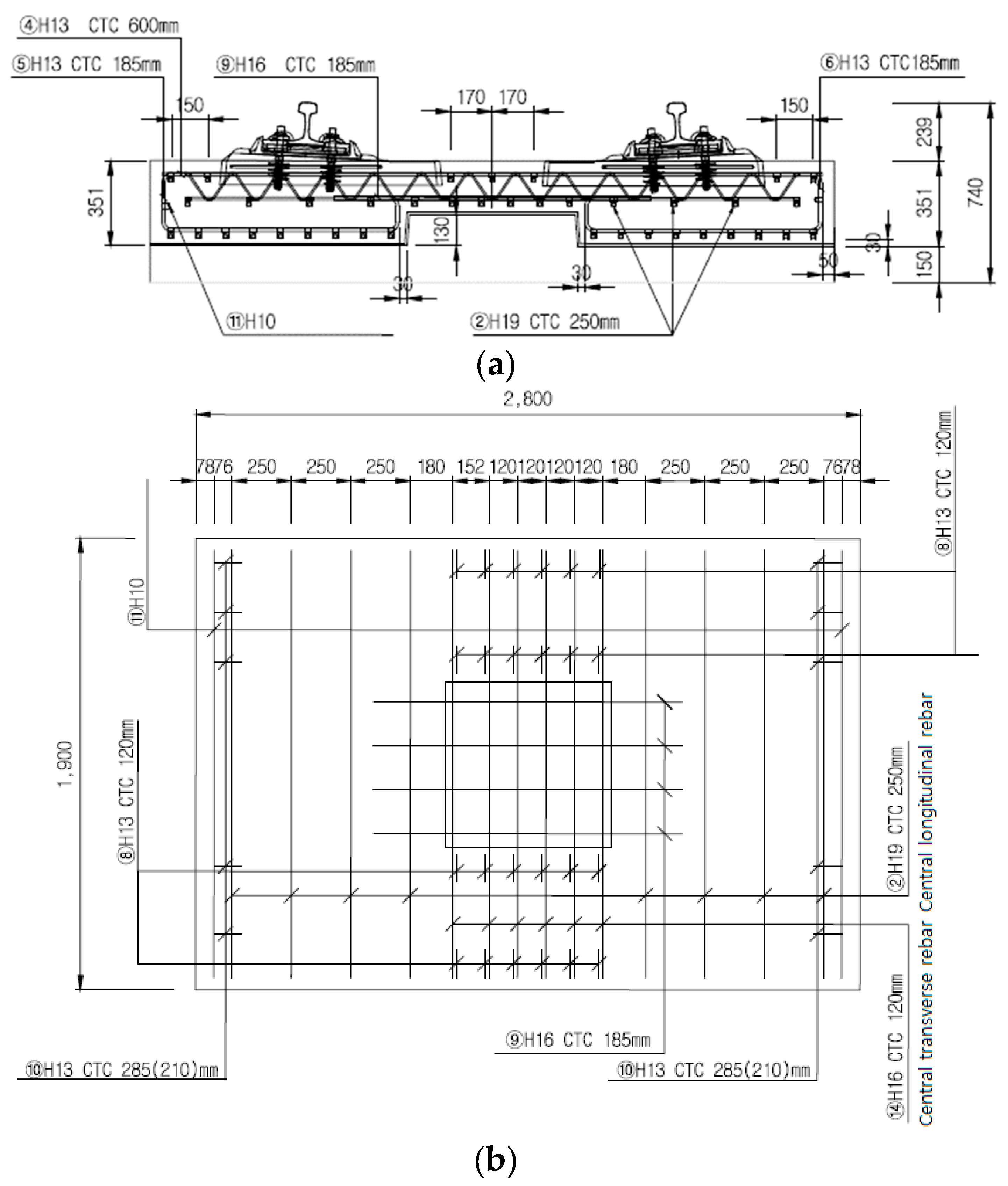
Figure 1. Flowchart for structural design of bridge track concrete slab. (a) Front view; (b) Longitudinal rebar arrangement.
Jcs 09 00597 g001
Figure 2. Manufacturing process of full-scale track concrete slab using GFRP rebar. (a) GFRP rebar arrangement; (b) Formwork installation; (c) Concrete casting and curing; (d) Specimen fabrication completed.
Jcs 09 00597 g002
Figure 3. Loading scenario for long-term fatigue tests.
Jcs 09 00597 g003
Figure 4. Experimental setup for long-term fatigue tests. (a) Specimen installation; (b) Loading setup details; (c) Loading cycles and measurement details.
Jcs 09 00597 g004
Figure 5. L/C displacements versus L/C load curves for the increased time under static loading. (a) Specimen using steel rebar; (b) Specimen using GFRP rebar.
Jcs 09 00597 g005
Figure 6. Comparison of L/C loads versus L/C displacements curves for GFRP and steel reinforcements under static loading.
Jcs 09 00597 g006
Figure 7. L/C displacements and change rates for increased fatigue loading cycles (Steel rebar). (a) L/C displacements for the increased loading cycles; (b) L/C displacement change rates for the increased loading cycles.
Jcs 09 00597 g007aJcs 09 00597 g007b
Figure 8. L/C displacements and change rates for increased fatigue loading cycles (GFRP rebar). (a) L/C displacements for the increased loading cycles; (b) L/C displacement change rates for the increased loading cycles.
Jcs 09 00597 g008aJcs 09 00597 g008b
Figure 9. Variations and increment rates in L/C loads for increased loading cycles (Steel rebar). (a) L/C load variations for the increased loading cycles; (b) Increment rates in L/C loads for the increased loading cycles.
Jcs 09 00597 g009aJcs 09 00597 g009b
Figure 10. Variations and increment rates in L/C loads for increased loading cycles (GFRP rebar). (a) L/C load variations for the increased loading cycles; (b) Increment rates in L/C loads for the increased loading cycles.
Jcs 09 00597 g010aJcs 09 00597 g010b
Figure 11. Variations in minimum and maximum L/C displacements for increased loading cycles (Steel rebar). (a) Minimum L/C displacement variations for the increased loading cycles; (b) maximum L/C displacement variations for the increased loading cycles.
Jcs 09 00597 g011aJcs 09 00597 g011b
Figure 12. Variations in minimum and maximum L/C displacements for increased loading cycles (GFRP rebar). (a) Minimum L/C displacement variations for the increased loading cycles; (b) maximum L/C displacement variations for the increased loading cycles.
Jcs 09 00597 g012aJcs 09 00597 g012b
Figure 13. Comparison of variations in L/C displacements versus loads for increased loading cycles. (a) Specimen using steel rebar; (b) Specimen using GFRP rebar.
Jcs 09 00597 g013aJcs 09 00597 g013b
Figure 14. Comparison of variations in L/C displacements and loads for increased loading cycles. (a) Specimen using steel rebar (b) Specimen using GFRP rebar.
Jcs 09 00597 g014
Figure 15. Final crack check after cycle loading (GFRP rebar).
Jcs 09 00597 g015
Table 1. Loading protocol for long-term fatigue tests.
ItemNotationUnitValues
Design axial load (Express railway)FkN220
Single wheel load1/2 × FkN110
Impact factori 1.2
Fatigue test load per single wheel loadF0 (=i × F/2)kN132
Increased load factorΦ 4/3
Design load per single wheel loadFd (=Φ × F0)kN176
Maximum fatigue test loadP0 (=2 × F0)kN264
Static cyclic loadPd (=2 × Fd)kN352
Fatigue minimum load per single wheel loadFminkN5
Minimum fatigue test loadPmin (=2 × Fmin)kN10
Disclaimer/Publisher’s Note: The statements, opinions and data contained in all publications are solely those of the individual author(s) and contributor(s) and not of MDPI and/or the editor(s). MDPI and/or the editor(s) disclaim responsibility for any injury to people or property resulting from any ideas, methods, instructions or products referred to in the content.