Article

Suppression of Delamination in CFRP Laminates with Ply Discontinuity Using Polyamide Mesh

1
Department of Mechanical & Aerospace Engineering, Faculty of Science and Technology, Tokyo University of Science, 2641 Yamazaki, Chiba 278-8510, Japan
2
Department of Mechanical Engineering, College of Science and Engineering, Aoyama Gakuin University, 5-10-1 Fuchinobe, Chuo-Ku, Kanagawa 252-5258, Japan
3
Division of Mechanical Engineering, Graduate School of Engineering, Osaka Metropolitan University, 1-1 Gakuen-Cho, Nakaku, Osaka 599-8531, Japan
4
School of Engineering, Newcastle University, Newcastle Upon Tyne NE1 7RU, UK
5
Department of Materials Science and Technology, Faculty of Advanced Engineering, Tokyo University of Science, 6-3-1, Niijuku, Tokyo 125-8585, Japan
*
Authors to whom correspondence should be addressed.
J. Compos. Sci. 2025, 9(8), 414; https://doi.org/10.3390/jcs9080414
Submission received: 30 June 2025 / Revised: 21 July 2025 / Accepted: 29 July 2025 / Published: 4 August 2025

Abstract

Carbon fiber-reinforced plastics (CFRPs) offer excellent in-plane mechanical performance, but their relatively low interlaminar fracture toughness makes them vulnerable to delamination, particularly around intralaminar discontinuities such as resin-rich regions or fiber gaps. This study investigates the effectiveness of polyamide (PA) mesh inserts in improving interlaminar toughness and suppressing delamination in CFRP laminates with such features. Two PA mesh configurations were evaluated: a fully embedded continuous layer and a 20 mm cut mesh strip placed between continuous and discontinuous plies near critical regions. Fracture toughness tests showed that PA mesh insertion improved interlaminar toughness approximately 2.4-fold compared to neat CFRP, primarily due to a mechanical interlocking mechanism that disrupts crack propagation and enhances energy dissipation. Uniaxial tensile tests with digital image correlation revealed that while initial matrix cracking occurred at similar stress levels, the stress at which complete delamination occurred was approximately 60% higher in specimens with a 20 mm mesh and up to 92% higher in specimens with fully embedded mesh. The fully embedded mesh provided consistent delamination resistance across the laminate, while the 20 mm insert localized strain redistribution and preserved global mechanical performance. These findings demonstrate that PA mesh is an effective interleaving material for enhancing damage tolerance in CFRP laminates with internal discontinuities.

1. Introduction

Carbon fiber-reinforced plastics (CFRPs) are exceptionally strong and lightweight, making them ideal for applications such as aircraft and automobiles. Their high strength-to-weight ratio and superior elasticity contribute to reduced fuel consumption and lower carbon dioxide emissions throughout the product lifecycle [1,2,3]. As CFRPs continue to be widely adopted across various industries, extensive research has been conducted to understand their damage mechanisms, service life, maintenance, and structural health monitoring [4,5]. A thorough understanding of their complex failure processes is essential for achieving robust and efficient designs in advanced engineering applications.
All CFRP laminates are prone to cumulative microscopic damage, including matrix cracks and delamination, which degrade mechanical properties and limit their use in structures subjected to high strain levels [6,7,8]. Transverse matrix cracks reduce stiffness and induce residual strains. Delamination, often initiating at the tips of such cracks, serves as a critical secondary damage mode that can propagate rapidly and cause structural failure [9,10]. Suppressing delamination is therefore a key challenge in enhancing the long-term durability and reliability of CFRP laminates, particularly in regions with complex internal architectures such as ply discontinuities [11].
Discontinuities are commonly introduced in industrial composite structures to enable cost-efficient, lightweight designs [12,13]. By selectively cutting prepregs at specific locations, material usage can be optimized, resulting in intentional fiber or ply terminations. The adoption of advanced manufacturing methods such as automated fiber placement has also enabled more flexible and efficient production of complex structures [14,15]. However, it has also introduced new types of defects, including resin-rich gaps and fiber misalignment. These manufacturing-induced flaws, combined with structural discontinuities, further increase local stress concentrations and the likelihood of interlaminar failure [16,17,18]. In regions where fiber or ply continuity is interrupted, excess resin tends to accumulate during curing, forming resin pockets that fill the spaces left by absent or misaligned fibers. Figure 1 illustrates examples of CFRP laminates with ply discontinuities and resin pockets: Figure 1a shows a resin pocket in a flat laminate, while Figure 1b shows resin pockets formed in tapered laminates. Understanding how ply discontinuities and associated resin pockets influence the damage behavior and mechanical performance of CFRP laminates is therefore essential.
To address these concerns, many studies have examined the effects of fiber or ply discontinuities on damage initiation, propagation, and failure in composite laminates—particularly in regions with ply drop-offs, including those arising from manufacturing defects—focusing on their impact on mechanical properties and damage initiation from discontinuous regions [17,18,19,20,21,22,23]. These investigations have shown that factors such as taper angle, step spacing, ply thickness, and resin pocket geometry significantly influence matrix cracking and delamination behavior. In addition to those studies, we have focused on evaluating microscopic damage mechanisms in simple unidirectional CFRP laminates with flat resin pocket configurations [24]. To gain a comprehensive understanding of damage behavior, numerical and analytical approaches have also been used to predict crack initiation and mechanical damage propagation caused by ply discontinuities [19,25,26,27].
As ply discontinuities in CFRP laminates trigger interlaminar damage such as delamination, primarily due to localized stress concentrations and resin-rich regions, it is necessary to enhance the interlaminar fracture toughness of laminates at these critical areas to suppress delamination and preserve structural integrity under mechanical loading. Although not specifically targeting critical regions with ply discontinuities, numerous strategies have been developed to enhance the overall properties of composite laminates. One widely studied approach to improving interlaminar fracture toughness involves incorporating interleaves and nanofillers in interlaminar regions to enhance energy dissipation and delay crack propagation. Thermoplastic fiber-based interleaves, such as polyimide, improve toughness through bridging mechanisms that absorb energy via deformation and debonding under load [28]. Similarly, combining nanoscale core–shell rubber particles with microscale short carbon fibers can substantially improve fracture toughness, with Veeramani et al. [29] reporting an increase of up to 127% compared to unmodified laminates. Rubber modified nanofibrous mats have also proven highly effective, with Maccaferri et al. [30] demonstrating a nearly 480% improvement in mode I fracture toughness. Polyetherimide hybrid systems enhance both mode I and mode II toughness [31], highlighting the important role of advanced polymer matrices in improving crack resistance.
Feather-inspired interleaves also show marked toughening capability by mimicking natural structures; Song et al. [32] reported a significant increase in interlaminar fracture toughness using a biomimetic interleaf inspired by feather shafts. Additionally, tailoring the microstructural heterogeneity within the toughening layer has emerged as an effective method, with Ou et al. [33] demonstrating enhanced fracture toughness in unidirectional CFRP laminates through optimized heterogeneity in the interleaf design.
In addition to material modifications, mechanical reinforcement techniques such as stitching and z-pinning offer through-thickness strengthening by inserting threads or pins perpendicular to the laminate layers, thereby restraining delamination and enhancing interlayer bonding [34]. Similarly, three-dimensional fiber architectures, such as woven, knitted, or braided composites, provide multidirectional reinforcement that improves load distribution and suppresses interlayer separation under mechanical or thermal stress [35].
Carbon nanotube interleaves have also gained attention for their multifunctional toughening potential. Functionalized multiwalled carbon nanotubes enhance both crack initiation and propagation resistance, achieving up to a 22% improvement in initiation toughness [36], while also contributing to electrical conductivity, which can support structural health monitoring [37]. However, their performance strongly depends on dispersion quality and matrix interaction, which may be hindered by resin viscosity and processing limitations [38]. Furthermore, interface engineering through precoating techniques has proven effective in improving interlaminar bonding and energy absorption, with Pan et al. [39] reporting that optimized interface treatments can balance mode I and mode II toughness across different laminate configurations.
Polyamide (PA) materials, with high melting points, good resin compatibility, and excellent mechanical properties, have been used in some studies as toughening interleaves in the form of micro/nanoparticles or nanofibers [40,41,42,43,44,45,46,47,48,49]. For example, Wang et al. [41] studied the inclusion of PA12 and PA6 particles (5 to 30 µm) in the interlaminar region of composites and identified toughening mechanisms such as crack deflection at the resin/particle interface, particle plastic deformation, and bridging. Zhao et al. [47] utilized low areal density PA66 fiber veils (4 to 10 g/m2) as interleaving layers in laminated composites, which, under delamination loading, exhibited significant fiber slippage, tearing, bridging, and fracture. These phenomena significantly enhanced the laminates’ energy absorption and interlaminar properties, with the 4 g/m2 PA66-interleaved composite showing increases of 13.6% in mode I and 139.8% in mode II fracture toughness, as well as improved shear and tensile strength. Nevertheless, the non-uniform structure and distribution of these PA materials may lead to inconsistent toughening performance. To address this limitation and achieve more reliable enhancement of interlaminar fracture toughness, the present study introduces PA mesh as a novel interleaving material. This approach aims to enhance interlaminar fracture toughness and effectively suppress the initiation of interlaminar damage in CFRP laminates, with particular emphasis on laminates containing intralaminar (ply-level) discontinuities. While many prior studies investigated general toughening approaches applied uniformly across the laminate, the novelty of this study lies in targeting critical regions, specifically ply discontinuities, where delamination is most likely to initiate due to local stress concentrations and resin accumulation.
In this study, the effectiveness of PA mesh in enhancing the interlaminar fracture toughness of CFRP laminates is experimentally evaluated through fracture tests on specimens with inserted mesh layers. Subsequently, PA mesh is strategically applied to critical regions near ply discontinuities, particularly resin-rich zones between continuous and discontinuous plies, to assess its ability to suppress delamination. Mechanical testing and damage observation are conducted to clarify the role of PA mesh in improving damage resistance and structural integrity. Furthermore, digital image correlation (DIC) is used to measure strain distribution during tensile loading, enabling evaluation of the mesh’s influence on the overall mechanical performance of the CFRP laminates.

2. Materials and Methods

2.1. Evaluation on the Interlaminar Fracture Toughness

To evaluate the interlaminar fracture toughness of CFRP laminates with inserted PA mesh, double cantilever beam (DCB) tests were conducted for mode I, and end notched flexure (ENF) tests were conducted for mode II.

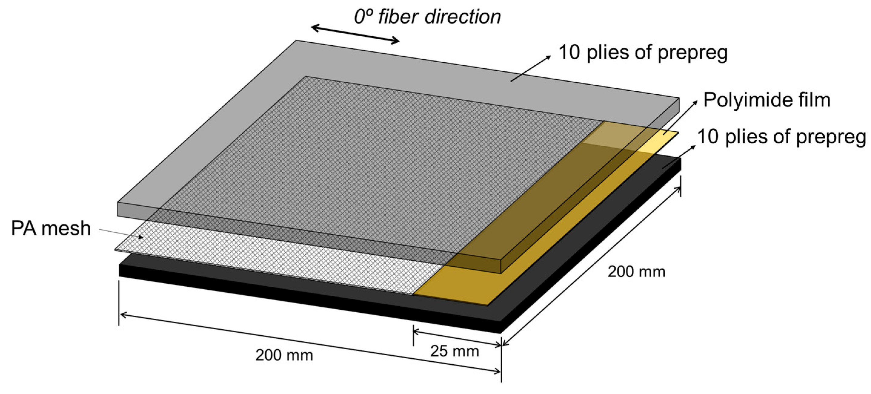
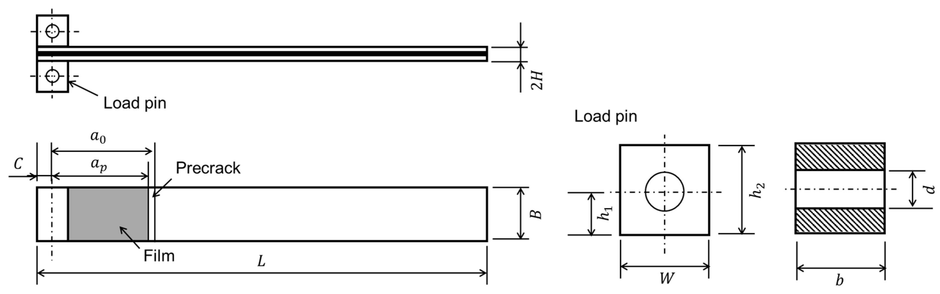
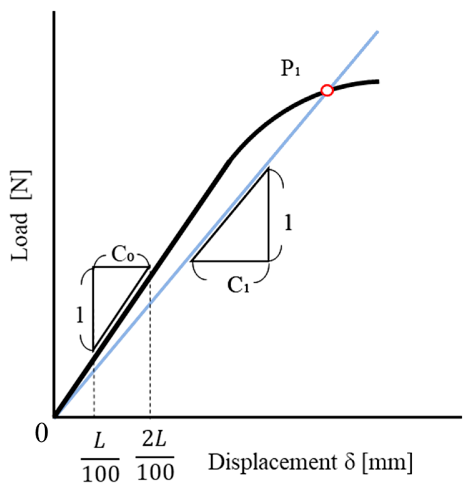
2.1.1. Mode I Interlaminar Fracture Toughness (DCB Test)

The test specimens were fabricated using T700SC/2592 CFRP prepreg (Toray Industries, Tokyo, Japan) with a fiber volume of 60% and a nominal thickness of 0.14 mm. A unidirectional (UD) [0]20 laminate was prepared by stacking 20 sheets of prepreg, each measuring 200 mm × 200 mm, into two sets of 10 plies. As illustrated in Figure 2, a PA mesh measuring 175 mm × 200 mm was inserted between the two stacked sets. The PA mesh (N-NO175T, NBC Meshtec Inc., Tokyo, Japan) had a fiber diameter of 50 µm, a thickness of 87 µm, and an opening of 95 µm. To introduce an initial crack, a 25 mm × 200 mm polyimide film with a thickness of 25 µm was placed between the upper and lower plies at the mid-plane. The laminate was cured using an autoclave (DANDELION 2010, Nagano, Japan) at 130 °C under a pressure of 0.2 MPa. Finally, the cured laminate was cut into test specimens using a precision cutting machine for composite materials (AC-300CF, Maruto, Tokyo, Japan). A schematic of the DCB test specimen configuration and its dimensions are shown in Figure 3 and Table 1, respectively.
A measuring microscope (VHX-1000, KEYENCE, Osaka, Japan) was used to measure the crack length during the DCB tests. Prior to measurement, the specimen edges were polished to enable crack tip observation for length measurement. Polishing was performed using a polisher (Tegrapol 15, Struers, Tokyo, Japan) with water as the lubricant and waterproof abrasive paper for grinding. The polishing process consisted of 1 min with 500 grit, 1 min 30 s with 1000 grit, 2 min with 2000 grit, and 2 min 30 s with 4000 grit paper. Finally, diamond polishing was performed using a diamond spray (DP Spray P–1 um, Struers, Tokyo, Japan) for 3 min to enhance the surface finish. Figure 4 shows the polished edge of a specimen.
DCB tests were carried out using a universal testing machine (SC-5H, JT Torsi Co., Kanagawa, Japan). In this study, measurements were taken of the load P , crack length a , and crack opening displacement (COD). Five specimens were tested. The first measurement was taken when the crack had propagated 3 mm from the initial crack, and subsequent measurements were made every 3 mm of crack propagation, with a total of five measurements per specimen. The loading speed was set at 0.5 mm/min up to 6 mm from the initial crack, and increased to 1.0 mm/min for crack propagation beyond 6 mm. Unloading was performed at a rate of 5.0 mm/min after each measurement. Mode I interlaminar fracture toughness G I was calculated using the following formula:
G I = 3 2 2 H P C B 2 B λ 2 3 α 1 ,
where P C is the critical load, λ is the compliance of the COD in the elastic portion of the load–COD curve, and α 1 is the slope of the linear approximation of the cube root of the compliance of the normalized crack length per unit width [50].

2.1.2. Mode II Fracture Toughness Evaluation (ENF Tests)

The materials used for specimen manufacturing in the ENF tests were identical to those used in the DCB tests. In this case, the laminates were cut to the dimensions shown in Figure 5 and detailed in Table 2. The edges of the specimens were then polished using the same technique as described previously.
Similar to the DCB tests, ENF tests were carried out using an SC-5H universal testing machine (JT Torsi Co., Kanagawa, Japan). In this study, measurements were taken of the load P and maximum deflection δ . Five specimens were tested. The load was applied at the midpoint of the support span, with a distance of 2 L = 70 mm, as shown in Figure 6. The test speed was set at 0.5 mm/min.
The mode II fracture toughness G I I C was calculated from Equation (2), where a 1 represents the estimated crack length at a specific load, calculated from Equation (3) [50]. Additionally, P 1 represents the specified load, C 0 denotes the compliance of the initial elastic part, and C 1 represents the compliance at a specified load, calculated from the load–COD curve. The maximum load P m a x was used as P 1 in this study. Figure 7 illustrates how C 1 and C 0 are determined.
G I I C = 9 a 0 2 P 1 2 C 1 2 B 2 L 3 + 3 a 1 3 ,
a 1 = C 1 C 0 a 0 3 + 2 3 C 1 C 0 1 L 3 1 3
For fractographic analysis after the DCB and ENF tests, the specimens were cut into small pieces and coated with gold by sputtering before observation under a scanning electron microscope (SEM) (KEYENCE, VE-7800, Osaka, Japan).

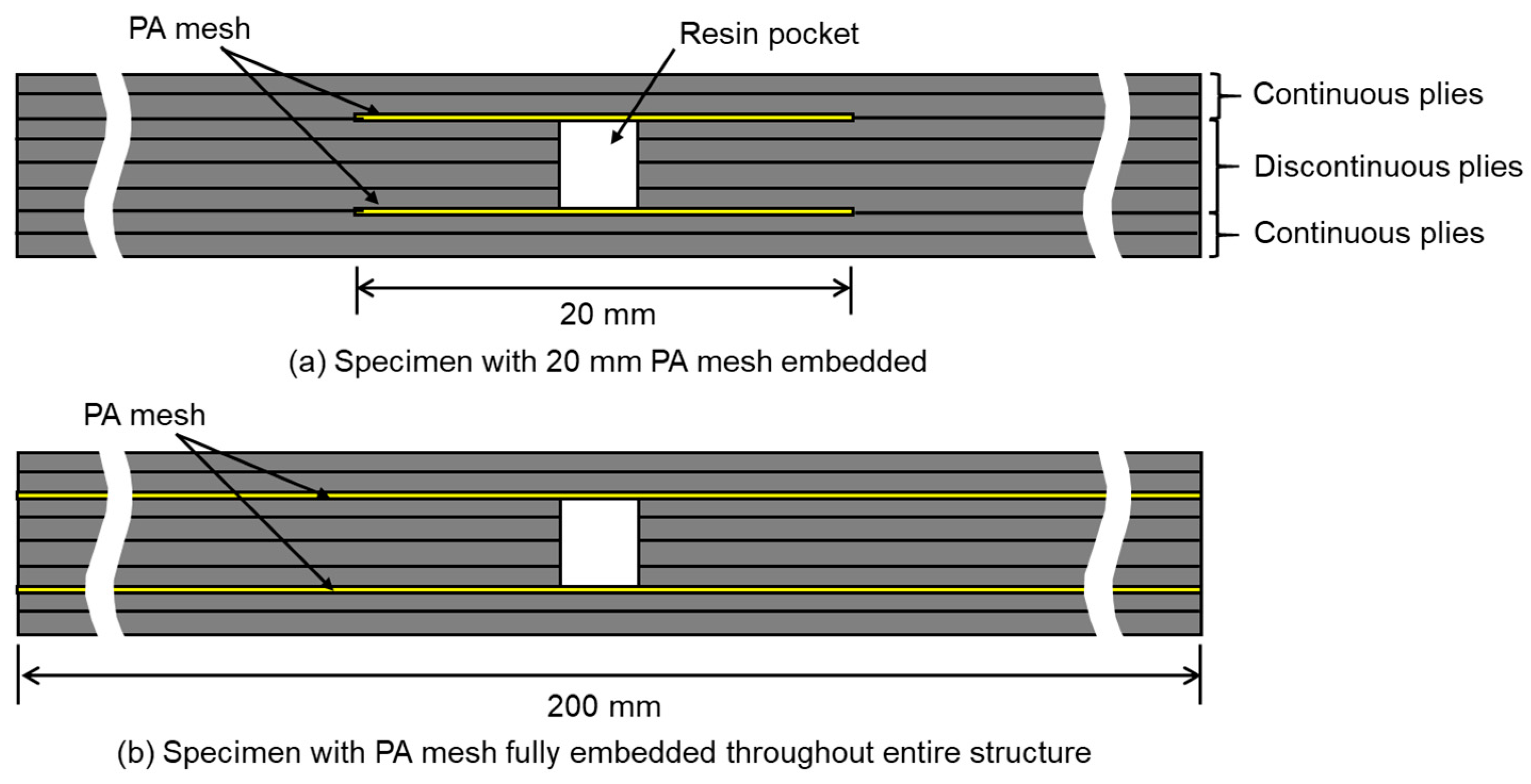
2.2. Application of PA Mesh in CFRP Laminates with Ply Discontinuities

To confirm the suppression of interlaminar delamination by inserting PA mesh, uniaxial tensile tests were conducted on UD CFRP laminates with ply discontinuities.

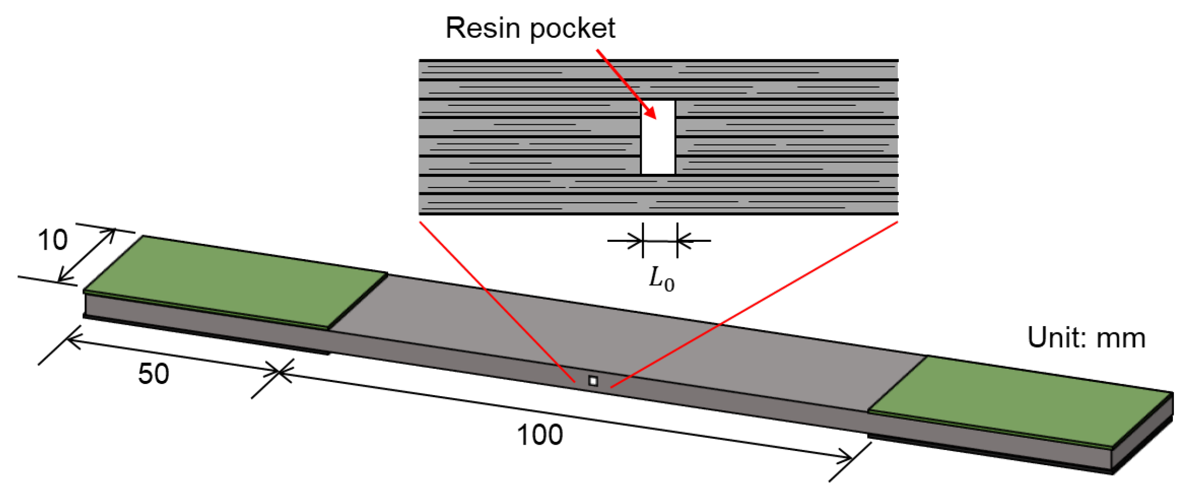
2.2.1. Laminate Configurations and Manufacturing

The laminate configuration of the specimens used in the uniaxial tensile tests was [02/PA/02]s. As illustrated in Figure 8, a stack of four UD tape prepreg plies was bisected perpendicularly to the fiber direction. The two halves were aligned with a predefined gap to form a symmetrical laminate structure, with PA meshes and continuous [0]2 UD laminates placed above and below the gap. The gap, or resin pocket length L 0 , was set to approximately 1 mm. Specimens were fabricated with either a 20 mm PA mesh embedded locally or with PA mesh fully embedded throughout the entire structure, as shown in Figure 9. This was performed to investigate whether local embedding of the PA mesh around critical regions such as ply discontinuities is sufficient to suppress delamination, or whether full embedding across the entire laminate is more effective in enhancing interlaminar fracture toughness. The CFRP prepreg, PA mesh materials, and manufacturing process described in Section 2.1 were used. During curing, resin from the adjacent UD plies flowed into the gap, forming a resin pocket that was cured simultaneously with the rest of the laminate. After cooling to room temperature, the laminate was sectioned into specimens, as shown in Figure 10.

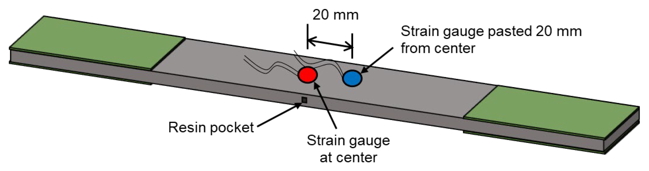
2.2.2. Tensile Tests and Damage Observation

Uniaxial tensile loading was applied at a crosshead speed of 0.5 mm/min using a TENSILON RTF-1350 tensile testing machine. To measure strain, two strain gauges, each with a gauge length of 5 mm (KFGS-5-120-C1-11L1M2R, Kyowa, Tokyo, Japan), were used. As shown in Figure 11, one strain gauge was adhered directly above the ply discontinuity area (resin pocket), while the other was affixed 20 mm from the center of the resin pocket to measure strain in the laminate without significant influence from the resin pocket. In situ edge observations were performed using a KEYENCE VHX-1000 optical microscope (lens: MX 7575CS, KEYENCE, Osaka, Japan) to verify the presence of damage.

3. Results and Discussion

3.1. Evaluation on the Interlaminar Fracture Toughness

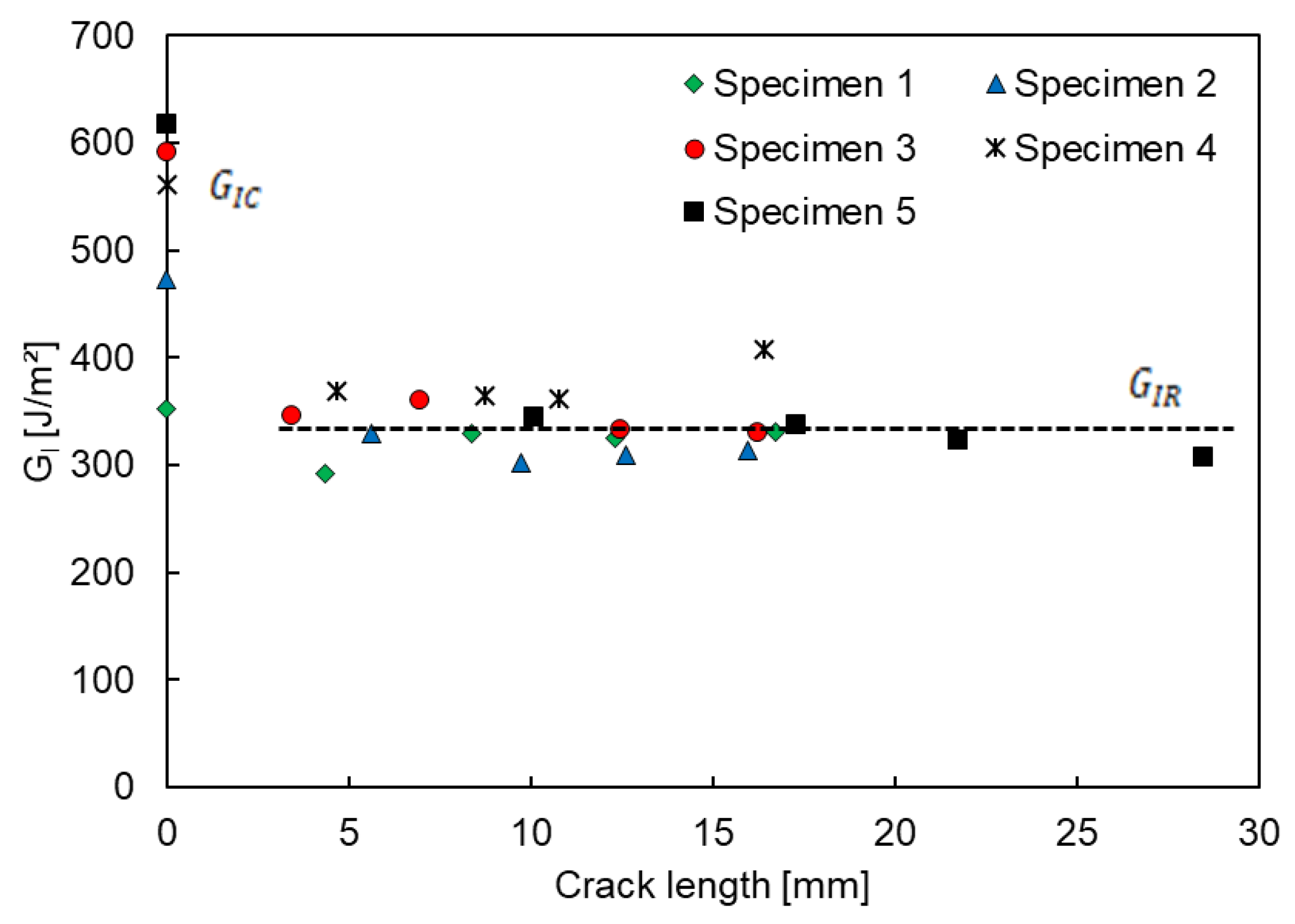
3.1.1. Mode I Interlaminar Fracture Toughness (DCB Tests)

Figure 12 shows the mode I fracture toughness ( G I )–crack length relationship for all specimens. The dotted lines indicate the average values of G I C and G I R , which were 519 J/m2 and 336 J/m2, respectively. G I C was calculated from the first loading cycle and represents the critical strain energy release rate required to initiate delamination. G I R , derived from subsequent cycles, represents the propagation strain energy release rate needed to sustain crack growth. Figure 13 displays bar charts comparing the G I C and G I R values of CFRP laminates with and without PA mesh inserts [11]. The error bars shown in the figure represent the standard deviations calculated from the test results of five specimens. G I C of the PA mesh-inserted laminate was higher than that of the neat laminate (348 J/m2), indicating improved resistance to crack initiation. However, G I R was lower than that of the neat CFRP (457 J/m2), suggesting reduced resistance to crack propagation.
Mode I fracture is characterized by crack surface opening perpendicular to the crack plane, often described as peeling. Although the inserted PA mesh increased the energy required for crack initiation, it did not effectively suppress crack propagation under this loading condition. This suggests that the current mesh configuration is insufficient to improve interlaminar toughness in mode I loading. Future work should explore mesh design modifications, such as finer mesh size, adjusted strand thickness, and altered orientation, to optimize both crack initiation resistance and propagation control.

3.1.2. Mode II Interlaminar Fracture Toughness (ENF Tests)

Figure 14 presents the load–deflection curves obtained from ENF tests conducted on five specimens. The peak loads for the specimens are highlighted with red dots. Figure 15 compares the mode II fracture toughness, G I I C , values between CFRP laminates with and without PA mesh inserts. G I I C values are averaged over five specimens and the error bars in the figure represent the corresponding standard deviations. The reference value for the neat CFRP laminate was obtained from [11]. The CFRP laminates incorporating a PA mesh insert exhibited a mode II fracture toughness approximately three times greater than that of the neat laminates.
To clarify the improvement in fracture toughness, fractography was conducted using SEM. Figure 16 and Figure 17 show the fractography results of a DCB and an ENF test specimen, respectively. Subfigure (a) in the figures presents the top surface, while subfigure (b) shows the bottom surface during the tests. On the top surface, the woven structure of the PA mesh is clearly visible, indicating that the mesh remained intact during fracture. In contrast, the bottom surface displays a clear imprint of the mesh pattern, replicating the geometry of the woven structure despite the absence of mesh on this side. Based on these SEM observations, it can be confirmed that the resin successfully penetrated the PA mesh structure, embedding well between the mesh fibers. Including the edge observation in Figure 4, no voids were observed at the interface, indicating good interfacial bonding quality. The imprint on the fractured surface suggests that the crack path was influenced by the physical presence of the mesh, providing evidence of a mechanical interlocking effect. Based on the SEM images, it can also be seen that the PA mesh fibers in the current study are aligned in the 0° and 90° directions, which reflects the intended fiber orientation during the insertion process.
By comparing the fracture surfaces under mode I (Figure 16a) and mode II (Figure 17a) loadings, it is evident that the PA mesh undergoes stretching deformation under mode II (shear) loading, particularly in the mesh fibers perpendicular to the direction of crack propagation, whereas no such deformation is observed under mode I loading. This indicates that, under shear loading, the PA mesh functions as a mechanical interlocking feature that disrupts the natural crack path. The crack is forced to deviate and navigate around the woven structure, thereby requiring additional energy for propagation. This deviation, together with interfacial friction contributes to the enhanced mode II fracture toughness. The presence of both the embedded mesh and its mirrored imprint, along with evidence of shear-induced deformation, supports the conclusion that the PA mesh improves resistance to shear-induced delamination through micromechanical toughening mechanisms.
The results clarify the role of PA mesh in enhancing the interlaminar fracture toughness of CFRP laminates under both mode I and mode II loading. While the mesh increased the resistance to crack initiation in mode I, it did not effectively suppress crack propagation due to the peeling nature of the fracture. In contrast, a significant improvement was observed under mode II loading, where the mesh disrupted the crack path through mechanical interlocking, requiring more energy for propagation. In actual structural applications, delamination typically occurs under mixed-mode loading rather than purely mode I or mode II. Considering the combined energy dissipation from both modes, the insertion of PA mesh leads to a clear overall enhancement in interlaminar fracture toughness. This demonstrates the effectiveness of PA mesh in improving the damage tolerance of CFRP laminates under realistic service conditions. However, further optimization of the mesh design and placement could enable better performance across a broader range of loading scenarios.

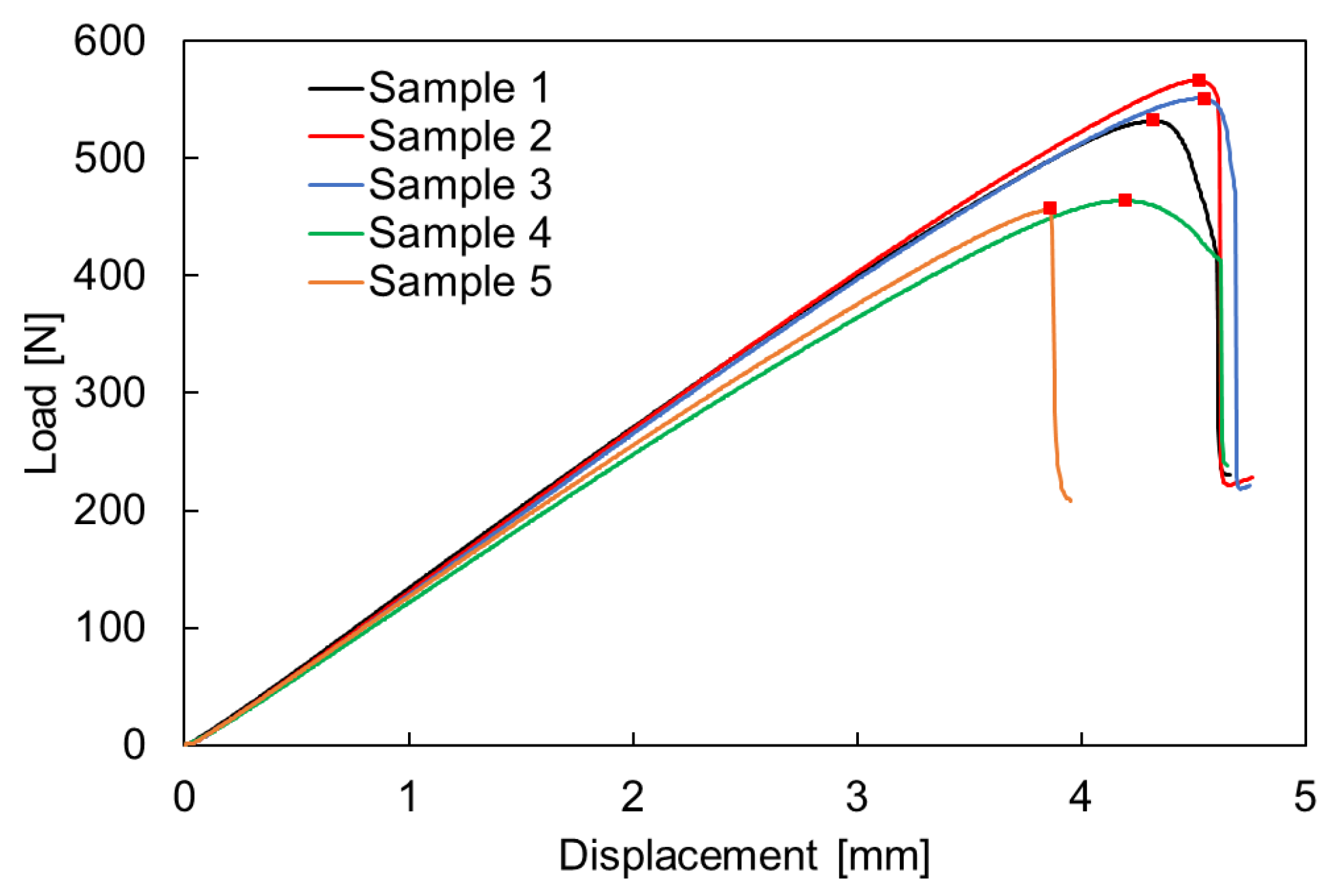
3.2. Application of PA Mesh in CFRP Laminates with Ply Discontinuities

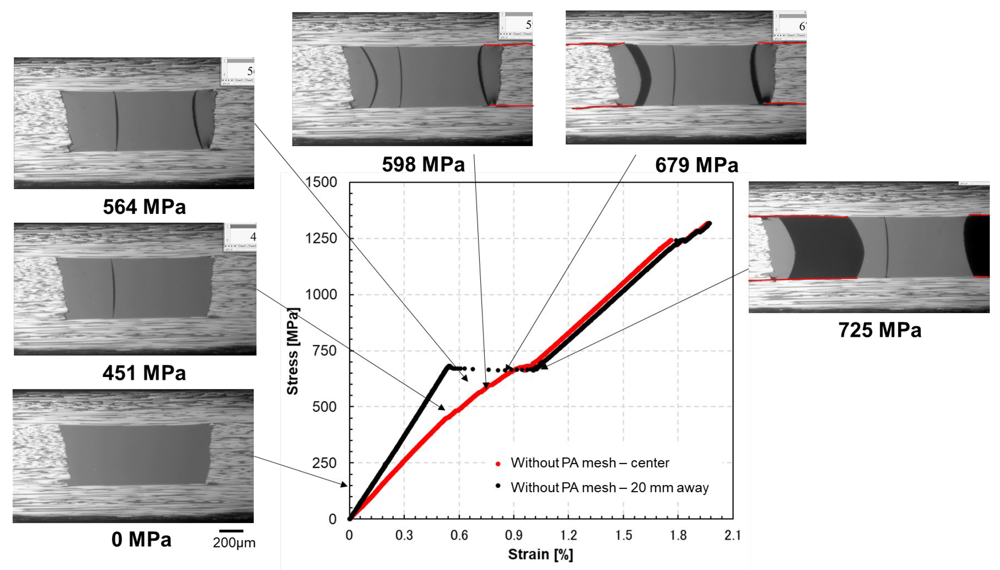
3.2.1. CFRP Laminate with No PA Mesh Embedded (Neat CFRP)

To validate the effectiveness of PA mesh in suppressing interlaminar delamination, the uniaxial tensile test results of CFRP laminates with embedded PA mesh were compared to those of neat CFRP laminates (without mesh insertion) from previous studies [24,26]. Figure 18 illustrates the representative stress–strain response of a neat specimen, accompanied by microscopic edge observations at selected stress levels during tensile loading.
From the nonlinearity (strain jumps) in the stress–strain curve and the corresponding edge observations shown in Figure 18, the onset of the first matrix crack was reported at 451 MPa [24,26]. A second matrix crack within the resin pocket appeared at 564 MPa, from which delamination initiated. The third matrix crack was observed at 679 MPa. In addition to the edge observations, the initiation and propagation of delamination were also indicated by a reduction in the slope of the stress–strain curve recorded by the centrally placed strain gauge following matrix cracking. Complete delamination between the continuous and discontinuous plies was confirmed to occur at approximately 725 MPa.

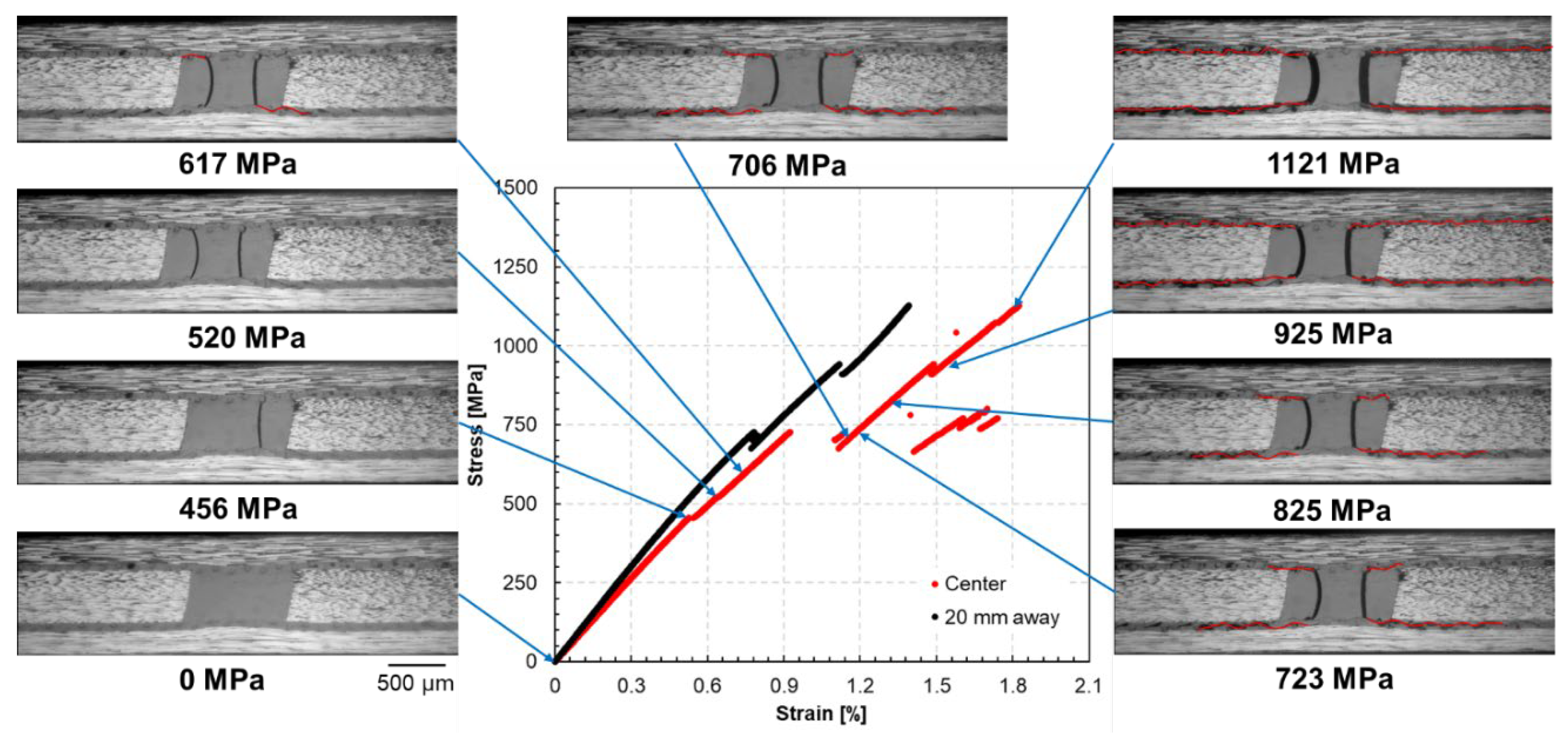
3.2.2. CFRP Laminate with 20 mm PA Mesh Embedded

The uniaxial tensile test results of specimens with 20 mm PA mesh embedded were compared to those of neat CFRP specimens. Figure 19 shows the stress–strain curves recorded by strain gauges placed at the center and 20 mm from the center for both types of specimens. Figure 20 presents the stress–strain curves along with edge observation results near the resin pocket at selected stress levels. The edge images were extracted from microscope video recordings captured during the test. The red lines overlaid on the images indicate the delamination propagation paths.
As shown in Figure 20, the first matrix crack in the resin pocket occurred at 456 MPa, followed by a second at 520 MPa. Small delamination from the matrix crack tips started to occur at 617 MPa, but the propagation was very slow as the applied stress increased. The decreasing slope of the stress–strain curve corresponds to the progression of delamination, indicating a loss of stiffness as the crack propagates. Above 600 MPa, while the slope of the curve for the neat CFRP specimen tended to decrease, the slope for the specimens with PA mesh inserts remained almost unchanged, showing linear behavior up to high stress levels. In other words, in the neat CFRP specimen, delamination progressed significantly above 600 MPa, whereas for the specimens with PA mesh inserts, it progressed slowly within the mesh layer even up to high stress levels.
A large strain jump was observed at approximately 720 MPa for the strain gauge pasted at the center, indicating a sudden delamination at all four edges of the resin pocket. At this point, the load continued to increase, and delamination progressed slowly up to a very high stress level of 1121 MPa. Complete separation between the continuous and discontinuous plies occurred at this stress level, leading to complete fracture soon after. This stress level is approximately 55% higher than that of the neat CFRP specimen, in which complete delamination occurred at about 725 MPa. This enhancement is attributed to the mechanical interlocking effect provided by the embedded PA mesh, which disrupts crack propagation and increases the energy required for delamination.

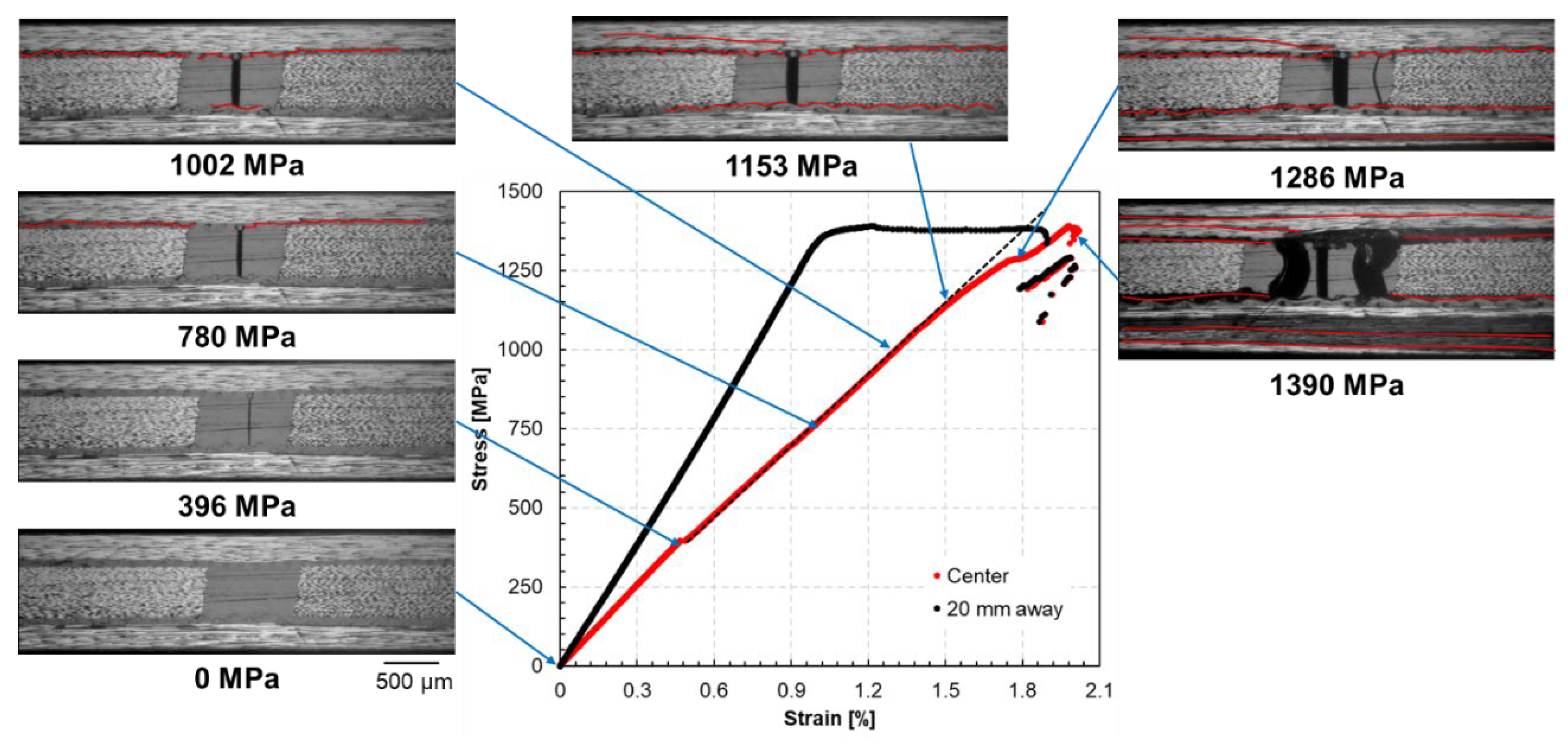
3.2.3. CFRP Laminate with PA Mesh Fully Embedded Throughout Entire Structure

The results of the uniaxial tensile test were compared between laminates with PA mesh fully embedded throughout their entire structure and neat CFRP specimens. The stress–strain curves are shown in Figure 21. Figure 22 presents the stress–strain curves and edge observation results (around the resin pocket) at specific applied stress levels.
The first matrix crack in the resin pocket occurred at 396 MPa, similar to the value for the neat CFRP specimen. The second matrix crack occurred at 1286 MPa, significantly higher than in the neat CFRP specimen and the specimen with a 20 mm PA mesh embedded. In those cases, the second crack usually occurred soon after the first, after which delamination started to propagate. However, in the specimen with the PA mesh fully embedded, the second crack occurred after significant delamination propagation. Above 600 MPa, while the slope of the curve for the neat CFRP specimen tended to decrease, the slope for the specimens with PA mesh inserts remained almost unchanged, showing linear behavior up to high stress levels. In other words, for neat CFRP specimens, delamination progressed significantly above 600 MPa, whereas in specimens with PA mesh inserts, it progressed slowly even up to high stress levels.
Delamination was first observed at 780 MPa in the edge observations and progressed slowly as the applied stress increased. At 1153 MPa, delamination also propagated between the continuous plies. This may have occurred because the enhanced interlaminar toughness between the continuous and discontinuous plies, due to the embedded PA mesh, caused the crack to propagate in locations where the fracture toughness was lower. Delamination between the continuous plies continued as the applied stress increased to 1286 MPa and 1390 MPa, as shown in Figure 22. Since delamination progressed very slowly in the specimen, it fractured immediately after complete ply separation at 1390 MPa. This final delamination stress was approximately 92% higher than that of the neat CFRP specimen (725 MPa), indicating a substantial improvement in delamination resistance. In this case, there was no large strain jump, and the stress–strain curves remained linear up to the high stress level of 1390 MPa. As previously noted, this improvement stems from the mechanical interlocking effect of the embedded PA mesh, which disrupts crack propagation and dissipates energy. Nevertheless, the tensile strength and fracture strain remained consistent with those of the neat CFRP laminate, indicating that mesh insertion does not compromise overall structural performance.

4. Effect of Embedded PA Mesh on Delamination and Mechanical Properties

Compared to neat CFRP laminates, those with PA mesh inserts show distinctly different stress–strain responses (Figure 19 and Figure 21). In neat specimens, delamination begins shortly after matrix cracking and progresses rapidly, causing a noticeable reduction in the slope of the stress–strain curve. In contrast, specimens with PA mesh, whether partially or fully embedded, maintain a stable initial slope, and delamination proceeds much more slowly. This result indicates that PA mesh effectively increases resistance to crack propagation and improves the mechanical performance of the laminate.
Based on the results obtained in this study, the laminates with fully embedded PA mesh suppress delamination more effectively than both the neat CFRP and the laminate with a 20 mm PA mesh insert. In the fully embedded configuration, delamination is significantly delayed and progresses very slowly, even under high applied stress. This enhanced performance is attributed to the mechanical interlocking effect of the PA mesh structure, which absorbs more energy and disrupts crack propagation throughout the entire laminate. Furthermore, the strength of the material, as indicated by the fracture stress and strain, remains comparable to that of the neat CFRP, indicating that the inclusion of PA mesh does not compromise the laminate strength.
Note that the results obtained in this study may not yet represent the optimal performance for delamination suppression. As discussed in Section 3.1.1, the propagation strain energy release rate ( G I R ) for mode I interlaminar fracture toughness suggests a limited ability to resist crack propagation once initiated. This indicates that the current PA mesh configurations have not been fully optimized for mode I loading conditions. Therefore, further research is needed to systematically investigate the influence of PA mesh dimensions and placement. A factorial design approach should be employed to optimize these parameters and maximize the improvement in fracture toughness, thereby fully exploiting the benefits of the embedded PA mesh structure.
To investigate the effect of embedding PA mesh in CFRP laminates, uniaxial tensile tests were conducted with full-field strain measurements using DIC in the axial, transverse, and shear directions. Figure 23 presents strain distribution maps obtained by DIC at approximately the same applied stress for three types of laminates: neat CFRP, CFRP with 20 mm embedded PA mesh, and CFRP with fully embedded PA mesh. In the axial strain field (Figure 23a), the laminates with 20 mm and fully embedded PA mesh exhibit localized high-strain concentrations originating near the resin pocket, indicating the onset of delamination. In contrast, the neat specimen displays a more pronounced axial strain distribution associated with complete delamination between the continuous and discontinuous plies. Given that complete delamination was observed in other neat specimens around 760 MPa, it is likely that delamination had also already progressed significantly in this case.
In the transverse strain field (Figure 23b), increased negative strain values are evident in the neat specimen, further indicating that the outer plies bear most of the load due to the loss of load transfer across the delaminated region, resulting in more pronounced transverse deformation. The PA mesh–reinforced laminates show different behavior: the fully embedded specimen generally exhibits a higher Poisson’s ratio across the entire area, reflecting a uniform transverse strain distribution, while the specimen with the 20 mm embedded mesh shows a localized increase in Poisson’s ratio around the delaminated region, indicating that transverse strain is more confined to this area.
In the shear strain field (Figure 23c), the laminate with fully embedded PA mesh shows notably high shear strain near the resin pocket, implying that the mesh contributes to interlaminar load transfer. On the other hand, the neat specimen exhibits very low shear strain within the delaminated region itself, while higher shear strain is concentrated in the upper and lower regions. This distribution is consistent with complete delamination, where interlaminar shear deformation can no longer be transmitted across the delaminated interface, causing the surrounding intact regions to accommodate the shear load.
While the fully embedded PA mesh specimens demonstrated superior suppression of delamination, it is important to highlight the advantages of localized insertion, such as the 20 mm mesh used in this study. Localized embedding improves interlaminar performance while preserving the original in-plane mechanical properties. Specifically, compared to the fully embedded mesh, the 20 mm PA mesh increased transverse and shear strain only around the delaminated region. This indicates that strain redistribution was localized and did not affect the global mechanical behavior of the laminate. Such behavior is particularly beneficial for applications where maintaining the original in-plane deformation characteristics is critical.
This study evaluated only uniaxial loading conditions, whereas actual structures are often subjected to more complex loading scenarios. Therefore, future studies should assess the long-term durability of PA mesh-interleaved laminates, particularly under fatigue loadings, to determine their suitability for realistic service environments. Additionally, the effects of the PA mesh on other mechanical properties such as bending strength, indentation resistance, impact performance, and out-of-plane behavior warrant further investigation. Furthermore, although this study employed a single PA mesh configuration in both the interlaminar fracture toughness evaluation and the application to laminates with ply discontinuities, optimizing key mesh parameters such as fiber diameter, thickness, and mesh opening is essential for further performance enhancement. A systematic investigation involving multiple PA mesh configurations is necessary to determine the optimal design for various laminate architectures and loading conditions.

5. Conclusions

This study examined the effectiveness of PA mesh as an interleaving material to enhance interlaminar performance in CFRP laminates with ply-level discontinuities such as resin pockets. Two configurations were tested: full laminate embedding and a 20 mm local mesh insert between continuous and discontinuous plies. Under mode II loading, the mesh improved interlaminar fracture toughness by approximately 2.4 times due to mechanical interlocking, which altered crack propagation paths and increased energy dissipation. Under mode I loading, the mesh enhanced crack initiation resistance but slightly reduced propagation resistance, likely due to local voids or weak bonding. This indicates the need for better mesh and resin interface design.
Uniaxial tensile tests revealed that while initial matrix cracking occurred at similar stress levels across all specimens, those with PA mesh showed significant suppression of delamination propagation. The 20 mm insert and the full embedding increased the stress at full delamination by approximately 55% and 92%, respectively. Local mesh placement effectively suppressed damage at critical regions without affecting overall tensile strength, while full embedding further improved delamination resistance at the cost of added transverse and shear strain. These findings demonstrate that PA mesh interleaving is a practical and scalable approach for improving delamination resistance in CFRP laminates. Further optimization through mixed-mode testing, fatigue evaluation, and interface engineering is recommended for demanding structural applications.

Author Contributions

Conceptualization, M.J.M.F., H.N. and S.O.; methodology, M.J.M.F., K.I. and H.N.; software, K.I. and S.Y.; validation, M.J.M.F., K.I. and V.V.; formal analysis, M.J.M.F. and K.I.; investigation, M.J.M.F., K.I. and H.N.; resources, S.O. and J.K.; data curation, M.J.M.F. and K.I.; writing—original draft, M.J.M.F.; writing—review and editing, M.J.M.F., K.I., H.N., S.Y., V.V., S.O. and J.K.; visualization, M.J.M.F. and K.I.; supervision, S.O., V.V., J.K. and S.Y.; project administration, M.J.M.F.; funding acquisition, M.J.M.F., J.K. and S.O. All authors have read and agreed to the published version of the manuscript.

Funding

A part of this work was supported by JKA and its promotion funds from KEIRIN RACE received by one of the co-authors (M. J. Mohammad Fikry).

Data Availability Statement

The raw data supporting the conclusions of this article will be made available by the authors on request.

Acknowledgments

During the preparation of this manuscript, the authors used ChatGPT (OpenAI, GPT-4, June 2025 version) for the purposes of language refinement, summarization, and clarity enhancement. The authors have reviewed and edited the output and take full responsibility for the content of this publication.

Conflicts of Interest

The authors declare no conflicts of interest.

Abbreviations

The following abbreviations are used in this manuscript:
CFRPCarbon fiber reinforced plastic
PAPolyamide
DCBDouble cantilever beam
ENFEnd-notched flexure
DICDigital image correlation
SEMScanning electron microscopy

References

  1. Zhang, J.; Lin, G.; Vaidya, U.; Wang, H. Past, present and future prospective of global carbon fibre composite developments and applications. Compos. Part B Eng. 2023, 250, 110463. [Google Scholar] [CrossRef]
  2. Hasebe, S.; Higuchi, R.; Yokozeki, T.; Takeda, S. Prediction of compression after impact strength from surface profile of low-velocity impact damaged CFRP laminates using machine learning. Compos. Part A Appl. Sci. Manuf. 2025, 189, 108560. [Google Scholar] [CrossRef]
  3. Rajak, D.K.; Wagh, P.H.; Linul, E. Manufacturing Technologies of Carbon/Glass Fiber-Reinforced Polymer Composites and Their Properties: A Review. Polymers 2021, 13, 3721. [Google Scholar] [CrossRef]
  4. Li, A.; Zhang, H.; Yang, D. Bearing performance and progressive failure analysis of bolted joint in 3D printed pseudo-woven CFRP composite with fibre steering. Compos. Part A Appl. Sci. Manuf. 2025, 188, 108526. [Google Scholar] [CrossRef]
  5. Yoneyama, S.; Koyanagi, J.; Arikawa, S. Measurement of discontinuous displacement/strain using mesh-based digital image correlation. Adv. Compos. Mater. 2015, 25, 329–343. [Google Scholar] [CrossRef]
  6. Ou, Y.; Zhu, D.; Zhang, H.; Yao, Y.; Mobasher, B.; Huang, L. Mechanical properties and failure characteristics of CFRP under intermediate strain rates and varying temperatures. Compos. Part B Eng. 2016, 95, 123–136. [Google Scholar] [CrossRef]
  7. Li, W.; Liu, Y.; Jiang, P.; Guo, F.; Cheng, J. Study on Delamination Damage of CFRP Laminates Based on Acoustic Emission and Micro Visualization. Materials 2022, 15, 1483. [Google Scholar] [CrossRef]
  8. Oshima, S.; Higuchi, R.; Kobayashi, S. Experimental characterization of cracking behavior initiating from microdefects in cross-ply CFRP laminates. Eng. Fract. Mech. 2023, 281, 109116. [Google Scholar] [CrossRef]
  9. Li, Y.; Wang, B.; Zhou, L. Study on the effect of delamination defects on the mechanical properties of CFRP composites. Eng. Fail. Anal. 2023, 153, 107576. [Google Scholar] [CrossRef]
  10. Bätzel, T.; Welker, C.; Hornig, A.; Stommel, M.; Spickenheuer, A.; Gude, M. Interlaminar properties of tailored fiber placement based CFRP laminates. Mech. Adv. Mater. Struct. 2025; 1–12, in press. [Google Scholar]
  11. Fikry, M.J.M.; Terashi, N.; Koizumi, K.; Ogihara, S. Inhibition of interlaminar damage in CFRP laminates by inserting non-woven carbon fiber interlaminar reinforced tissue. Adv. Compos. Mater. 2024, 34, 513–533. [Google Scholar] [CrossRef]
  12. Woigk, W.; Zhang, B.; Jones, M.I.; Kuhtz, M.; Hornig, A.; Gude, M.; Hallett, S.R. Effect of saw-tooth ply drops on the mechanical performance of tapered composite laminates. Compos. Struct. 2021, 272, 114197. [Google Scholar] [CrossRef]
  13. Nakatani, H.; Nakaya, K.; Matsuba, A.; Kouno, Y.; Ogihara, S. Effect of prepreg cut on the mechanical properties in CFRP laminates. J. Solid Mech. Mater. Eng. 2011, 5, 742–752. [Google Scholar] [CrossRef]
  14. Kukwi, T.; Shan, C.; Pengfei, L.; Zhang, B.; Leiyang, G.; Wang, Z. Continuous improvement in composite manufacturing: A review of automated fiber placement process evolution and future research prospects. Appl. Compos. Mater. 2025; in press. [Google Scholar]
  15. Xu, X.; Cheng, L.; Cai, Z.; Li, J.; Ke, Y. Multi-source lay-up error analysis and lay-up pressure optimization for robotic automated fiber placement (AFP). Compos. Part A Appl. Sci. Manuf. 2025, 193, 108825. [Google Scholar] [CrossRef]
  16. Simacek, P.; Minakuchi, S.; Advani, S.G. A model to describe transient transverse deformation during prepreg consolidation. Compos. Part A Appl. Sci. Manuf. 2025, 197, 109021. [Google Scholar] [CrossRef]
  17. He, K.; Hoa, S.V.; Ganesan, R. The study of tapered laminated composite structures: A review. Compos. Sci. Technol. 2000, 60, 2643–2657. [Google Scholar] [CrossRef]
  18. Fikry, M.J.M.; Vinogradov, V.; Ogihara, S. Mechanical properties and damage behavior of tapered unidirectional CFRP laminates. Mech. Eng. J. 2023, 10, 23-00079. [Google Scholar] [CrossRef]
  19. Lu, X.; Higuchi, R.; Hua, X.; Nagashima, T.; Yokozeki, T. Experimental and numerical study on failure mechanisms of tapered laminates: Effects of ply thickness and taper ratio. Compos. Sci. Technol. 2024, 256, 110784. [Google Scholar] [CrossRef]
  20. Minakuchi, S.; Takeda, N. Ply curving termination to suppress delamination in composite ply drop-off. In ICAF 2019—Structural Integrity in the Age of Additive Manufacturing; Niepokolczycki, A., Komorowski, J., Eds.; Springer: Cham, Switzerland, 2020; pp. 124–132. [Google Scholar]
  21. Ohashi, N.; Yoshida, T.; Minakuchi, S. Ply curving termination for enhancing tensile strength of composite ply drop-off: Static evaluation and failure mechanism. Adv. Compos. Mater. 2025, 34, 307–328. [Google Scholar] [CrossRef]
  22. Zhang, B.; Kawashita, L.F.; Jones, M.I.; Lander, J.K.; Hallett, S.R. An experimental and numerical investigation into damage mechanisms in tapered laminates under tensile loading. Compos. Part A Appl. Sci. Manuf. 2020, 133, 105862. [Google Scholar] [CrossRef]
  23. Minakuchi, S.; Simacek, P.; Advani, S.G. In-situ consolidation deformation of composite laminate with gaps of various widths. Compos. Part A Appl. Sci. Manuf. 2024, 180, 108054. [Google Scholar] [CrossRef]
  24. Fikry, M.J.M.; Arai, Y.; Inoue, R.; Vinogradov, V.; Tan, K.T.; Ogihara, S. Damage behavior in unidirectional CFRP laminates with ply discontinuity. Appl. Compos. Mater. 2025; 1–19, in press. [Google Scholar]
  25. Gan, K.W.; Allegri, G.; Hallett, S.R. A simplified layered beam approach for predicting ply drop delamination in thick composite laminates. Mater. Des. 2016, 108, 570–580. [Google Scholar] [CrossRef]
  26. Fikry, M.J.M.; Vinogradov, V.; Ogihara, S. Experimental observation and modeling of resin pocket cracking in unidirectional laminates with ply discontinuity. Compos. Sci. Technol. 2022, 218, 109175. [Google Scholar] [CrossRef]
  27. Fikry, M.J.M.; Vinogradov, V.; Ogihara, S. Analytical prediction of the local Young’s modulus in CFRP laminate with ply discontinuity: A variational approach. Adv. Compos. Mater. 2023, 32, 843–865. [Google Scholar] [CrossRef]
  28. Chen, L.; Wu, L.-W.; Jiang, Q.; Tian, D.; Zhong, Z.; Wang, Y.; Fu, H.-J. Improving interlaminar fracture toughness and impact performance of carbon fiber/epoxy laminated composite by using thermoplastic fibers. Molecules 2019, 24, 3367. [Google Scholar] [CrossRef]
  29. Veeramani, N.; Devine, M.; Quinn, J.A.; Alapati, A.K.; Bolluk, A.; Ray, D. Enhancing fracture toughness of carbon fiber/epoxy composites using polyphenylene ether as a modifier. J. Appl. Polym. Sci. 2024, 141, e55388. [Google Scholar] [CrossRef]
  30. Maccaferri, E.; Mazzocchetti, L.; Benelli, T.; Brugo, T.M.; Zucchelli, A.; Giorgini, L. Rubbery-modified CFRPs with improved Mode I fracture toughness: Effect of nanofibrous mat grammage and positioning on tanδ behaviour. Polymers 2021, 13, 1918. [Google Scholar] [CrossRef]
  31. Wang, J.; Pozegic, T.R.; Xu, Z.; Nigmatullin, R.; Harniman, R.L.; Eichhorn, S.J. Cellulose nanocrystal-polyetherimide hybrid nanofibrous interleaves for enhanced interlaminar fracture toughness of carbon fibre/epoxy composites. Compos. Sci. Technol. 2019, 182, 107744. [Google Scholar] [CrossRef]
  32. Song, W.; Chen, Y.; Mu, Z.; Wang, Y.; Zhang, Z.; Wang, Z.; Liu, L.; Zhang, B.; Li, Y.; Li, B.; et al. A feather-inspired interleaf for enhanced interlaminar fracture toughness of carbon fiber reinforced polymer composites. Compos. Part B Eng. 2022, 236, 109827. [Google Scholar] [CrossRef]
  33. Ou, Y.; Fu, A.; Wu, L.; Yi, X.; Mao, D. Enhanced interlaminar fracture toughness of unidirectional CFRP laminates with tailored microstructural heterogeneity of toughening layer. Compos. Part A Appl. Sci. Manuf. 2024, 176, 107872. [Google Scholar] [CrossRef]
  34. Sun, X.; Liu, H.-Y.; Yan, W.; Tong, L.; Mai, Y.-W. Modelling composite reinforcement by stitching and z-pinning. In Multi-Scale Modelling of Composite Material Systems; Woodhead Publishing: Cambridge, UK, 2005; pp. 319–355. [Google Scholar]
  35. Tong, L.; Mouritz, A.P.; Bannister, M.K. 3D Fibre Reinforced Polymer Composites; Elsevier Science Ltd.: Oxford, UK, 2002. [Google Scholar]
  36. Borowski, E.; Soliman, E.; Kandil, U.F.; Taha, M.R. Interlaminar fracture toughness of CFRP laminates incorporating multi-walled carbon nanotubes. Polymers 2015, 7, 1020–1045. [Google Scholar] [CrossRef]
  37. Xu, F.; Yang, B.; Feng, L.; Huang, D.; Xia, M. Improved interlaminar fracture toughness and electrical conductivity of CFRPs with non-woven carbon tissue interleaves composed of fibers with different lengths. Polymers 2020, 12, 803. [Google Scholar] [CrossRef]
  38. Sager, R.; Klein, P.; Davis, D.; Lagoudas, D.C.; Warren, G.L.; Sue, H. Interlaminar fracture toughness of woven fabric composite laminates with carbon nanotube/epoxy interleaf films. J. Appl. Polym. Sci. 2011, 121, 2394–2405. [Google Scholar] [CrossRef]
  39. Pan, Y.; Wu, G.; Cheng, X.; Zhang, Z.; Li, M.; Ji, S.; Huang, Z. Mode I and Mode II interlaminar fracture toughness of CFRP/magnesium alloys hybrid laminates. Compos. Interfaces 2016, 23, 453–465. [Google Scholar] [CrossRef]
  40. Topzeven. Meshes, Plastic Mesh, Nylon (PA) Mesh (Woven). Available online: https://www.topzeven.com/meshes-2/plastic-mesh-nylon-pa-mesh/?lang=en (accessed on 20 April 2024).
  41. Wang, W.-T.; Yu, H.; Potter, K.; Kim, B.C. Effect of the characteristics of nylon microparticles on Mode-I interlaminar fracture toughness of carbon-fibre/epoxy composites. Compos. Part A Appl. Sci. Manuf. 2020, 138, 106073. [Google Scholar] [CrossRef]
  42. Wang, C.; He, Y.; Lin, Z.; Zhao, X.; Sun, C.; Guo, R.; Wang, X.; Zhou, F. Mechanical and tribological properties of FDM-printed polyamide. Tribol. Int. 2024, 191, 109198. [Google Scholar] [CrossRef]
  43. Kovács, T.; Simon-Stőger, L.; Heller, B.; Cs, V. Enhancing properties of PC/PA blends via compatibilization of olefin-maleic-anhydride copolymer based additives in masterbatch form. J. Polym. Res. 2021, 28, 294. [Google Scholar] [CrossRef]
  44. Dai, R.; Huang, M.; Ma, L.; Liu, W.; He, S.; Liu, H.; Zhu, C.; Wang, Y.; Zhang, Z.; Sun, A. Study on crystal structure and phase transitions of polyamide 12 via wide-angle X-ray diffraction with variable temperature. Adv. Compos. Hybrid Mater. 2020, 3, 522–529. [Google Scholar] [CrossRef]
  45. Beylergil, B.; Tanoğlu, M.; Aktaş, E. Effect of polyamide-6,6 (PA 66) nonwoven veils on the mechanical performance of carbon fiber/epoxy composites. Compos. Struct. 2018, 194, 21–35. [Google Scholar] [CrossRef]
  46. Marino, S.G.; Košťáková, E.K.; Czél, G. Development of pseudo-ductile interlayer hybrid composites of standard thickness plies by interleaving polyamide 6 nanofibrous layers. Compos. Sci. Technol. 2023, 234, 109924. [Google Scholar] [CrossRef]
  47. Zhao, Q.; Yang, Z.; Xue, Y.; Feng, Y.; Zhang, W.; Peng, Y.; Liu, Y.; Zhang, H.; Yu, J. Performance of interlayer toughened carbon fiber/epoxy composites of low areal density PA66 fiber veil. Acta Mater. Compos. Sin. 2025, 42, 263–271. [Google Scholar]
  48. Meireman, T.; Daelemans, L.; Rijckaert, S.; Rahier, H.; Van Paepegem, W.; De Clerck, K. Delamination resistant composites by interleaving bio-based long-chain polyamide nanofibers through optimal control of fiber diameter and fiber morphology. Compos. Sci. Technol. 2020, 193, 108126. [Google Scholar] [CrossRef]
  49. Daelemans, L.; Kizildag, N.; Van Paepegem, W.; D’hooge, D.R.; De Clerck, K. Interdiffusing core-shell nanofiber interleaved composites for excellent mode I and mode II delamination resistance. Compos. Sci. Technol. 2019, 175, 143–150. [Google Scholar] [CrossRef]
  50. J.I.S. K7086-1993; Testing Methods for Interlaminar Fracture Toughness of Carbon Fibre Reinforced Plastics. Japanese Standards Association: Tokyo, Japan, 1993.
Figure 1. Examples of composite laminates with ply discontinuities and resin pockets: (a) resin pocket formed in a flat laminate due to ply termination; (b) resin pockets observed in tapered laminates resulting from gradual ply drop-offs.
Jcs 09 00414 g001
Figure 2. Illustration of the lay-up structure of a laminate for interlaminar fracture toughness evaluation.
Jcs 09 00414 g002
Figure 3. Schematic specimen configuration for DCB tests.
Jcs 09 00414 g003
Figure 4. Edge observation of a polished specimen used for interlaminar fracture toughness evaluation.
Jcs 09 00414 g004
Figure 5. Schematic specimen configuration for ENF tests.
Jcs 09 00414 g005
Figure 6. Schematic for ENF test setup.
Jcs 09 00414 g006
Figure 7. Determination of C 0 and C 1 .
Jcs 09 00414 g007
Figure 8. Illustration of laminate with discontinuous plies and embedded PA mesh.
Jcs 09 00414 g008
Figure 9. Placement of PA mesh in the specimen: (a) Specimen with 20 mm PA mesh embedded; (b) specimen with PA mesh fully embedded throughout entire structure.
Jcs 09 00414 g009
Figure 10. Specimen measurement for uniaxial tensile tests.
Jcs 09 00414 g010
Figure 11. Strain gauge placement on a specimen.
Jcs 09 00414 g011
Figure 12. Mode I fracture toughness G I –crack length relationship for all specimens. Dotted lines show average G I values.
Jcs 09 00414 g012
Figure 13. Comparison of mode I interlaminar fracture toughness between neat CFRP laminate and CFRP laminate with PA mesh insert.
Jcs 09 00414 g013
Figure 14. Load–deflection curves from ENF tests. Red dots represent the maximum loads in the tests.
Jcs 09 00414 g014
Figure 15. Comparison of mode II interlaminar fracture toughness between neat CFRP laminate and CFRP laminate with PA mesh insert.
Jcs 09 00414 g015
Figure 16. Fractography of DCB test specimen using SEM: (a) top surface (side with mesh); (b) bottom surface (side with mesh imprint).
Jcs 09 00414 g016
Figure 17. Fractography of ENF test specimen using SEM: (a) top surface (side with mesh); (b) bottom surface (side with mesh imprint).
Jcs 09 00414 g017
Figure 18. Stress–strain curves and microscopic edge observations (around the resin pocket) captured at selected stress levels during the tensile test of a specimen with no PA mesh embedded [24,26]. Reproduced with permission from M. J. Mohammad Fikry, Composites Science and Technology; published by Elsevier, 2022.
Jcs 09 00414 g018
Figure 19. Stress–strain curves from the tensile test of a specimen with a 20 mm PA mesh embedded, in comparison to neat CFRP specimen.
Jcs 09 00414 g019
Figure 20. Stress–strain curves and results of edge observations (around the resin pocket) at specific applied stress levels for a specimen with a 20 mm PA mesh embedded. The red lines in the images indicate delamination propagation paths.
Jcs 09 00414 g020
Figure 21. Stress–strain curves from the tensile test of a specimen with PA mesh fully embedded throughout its entire structure, compared to a specimen without an inserted PA mesh interlayer.
Jcs 09 00414 g021
Figure 22. Stress–strain curves and edge observation results at specific applied stress levels for a specimen with PA mesh fully embedded throughout its entire structure.
Jcs 09 00414 g022
Figure 23. Strain distribution maps obtained by DIC at approximately the same applied stress: (a) axial strain, (b) transverse strain, and (c) shear strain for neat CFRP, CFRP with embedded 20 mm PA mesh, and CFRP with fully embedded PA mesh.
Jcs 09 00414 g023
Table 1. Specimen dimensions for DCB tests.
PartSymbolDimensionSize [mm]
DCB specimen L Length90
2 H Thickness2.3
B Width10
C Distance from specimen end load line6
a p Film crack length25
a 0 Precrack length28–32
Load pin W Width12
b Length12
h 1 Half height6
h 2 Height12
d Hole diameter5
Table 2. Specimen dimensions for ENF tests.
SymbolPartsSize [mm]
L Length110
2 H Thickness2.3
B Width10
CDistance from specimen end load line20
a p Film crack length25
a 0 Precrack length31–35
Disclaimer/Publisher’s Note: The statements, opinions and data contained in all publications are solely those of the individual author(s) and contributor(s) and not of MDPI and/or the editor(s). MDPI and/or the editor(s) disclaim responsibility for any injury to people or property resulting from any ideas, methods, instructions or products referred to in the content.

