Article

Bond Behavior Between Fabric-Reinforced Cementitious Matrix (FRCM) Composites and Different Substrates: An Experimental Investigation

College of Civil Engineering, Lanzhou Institute of Technology, Lanzhou 730050, China
*
Author to whom correspondence should be addressed.
J. Compos. Sci. 2025, 9(8), 407; https://doi.org/10.3390/jcs9080407 (registering DOI)
Submission received: 7 July 2025 / Revised: 26 July 2025 / Accepted: 30 July 2025 / Published: 1 August 2025

Abstract

This study investigates the bond behavior of fabric-reinforced cementitious matrix (FRCM) composites with three common masonry substrates—solid clay bricks (SBs), perforated bricks (PBs), and concrete hollow blocks (HBs)—using knitted polyester grille (KPG) fabric. Through uniaxial tensile tests of the KPG fabric and FRCM system, along with single-lap and double-lap shear tests, the interfacial debonding modes, load-slip responses, and composite utilization ratio were evaluated. Key findings reveal that (i) SB and HB substrates predominantly exhibited fabric slippage (FS) or matrix–fabric (MF) debonding, while PB substrates consistently failed at the matrix–substrate (MS) interface, due to their smooth surface texture. (ii) Prism specimens with mortar joints showed enhanced interfacial friction, leading to higher load fluctuations compared to brick units. PB substrates demonstrated the lowest peak stress (69.64–74.33 MPa), while SB and HB achieved comparable peak stresses (133.91–155.95 MPa). (iii) The FRCM system only achieved a utilization rate of 12–30% in fabric and reinforcement systems. The debonding failure at the matrix–substrate interface is one of the reasons that cannot be ignored, and exploring methods to improve the bonding performance between the matrix–substrate interface is the next research direction. HB bricks have excellent bonding properties, and it is recommended to prioritize their use in retrofit applications, followed by SB bricks. These findings provide insights into optimizing the application of FRCM reinforcement systems in masonry structures.

1. Introduction

Masonry structures, as the primary form of historical and early civil buildings, commonly suffer from material aging and insufficient seismic resistance. Statistics indicate that approximately 60% of existing masonry buildings in China were constructed before the establishment of modern seismic codes [1]. Proper reinforcement can significantly enhance the flexural and shear capacity of such structures [2,3]. In recent years, with the development of novel composite materials and diversified strengthening techniques, the repair and reinforcement of existing masonry structures have gained increasing popularity.
As a typical representative of organic systems, fiber-reinforced polymer (FRP) composites have attracted widespread attention in civil engineering, due to their high tensile strength, corrosion resistance, and lightweight yet robust properties [4,5]. The Italian design guideline CNR-DT 200/2006 [6] includes a dedicated chapter on masonry structures, demonstrating academic recognition of FRP reinforcement for masonry applications. However, further research has revealed inherent limitations of FRP, such as poor breathability, incompatibility with wet or low-temperature surfaces, low heat resistance [7,8,9], poor compatibility with masonry substrates [10,11,12], and relatively high costs [11,13,14]. These drawbacks have restricted the widespread adoption of FRP in the reinforcement of existing masonry structures. Moreover, once the shear capacity of the reinforcement system is exceeded, debonding failure occurs as the FRP layer separates from the substrate. Studies [15,16] have shown that debonding is often associated with the removal of reinforcement materials, as the substrate exhibits lower tensile strength compared to epoxy resins and fiber materials.
Debonding failure, as a common failure mode, leads to premature separation of the composite material from the substrate before its full reinforcement efficiency is realized. Therefore, investigating the bond behavior between composite materials and substrates (e.g., brick, concrete) is of great significance, prompting extensive research on this topic [14,17,18,19,20,21].
To address the stringent surface requirements of FRP for masonry substrates and to overcome the inherent flaws of epoxy resins, new inorganic reinforcement systems have emerged as alternatives to organic systems. These include fabric-reinforced cementitious matrix (FRCM) composites—also referred to as inorganic matrix grid (IMG) [22,23,24], textile-reinforced mortar (TRM) [10,11,25,26,27,28], or fabric-reinforced cementitious matrix (FRCM) [29,30,31,32] and steel-reinforced grout (SRG) composites [13,33,34,35,36,37]. These methods offer advantages such as ease of application, rapid construction, superior bond deformation performance, and cost-effectiveness, providing flexible reinforcement solutions for diverse conditions and requirements.
A literature review on inorganic composite reinforcement for masonry structures is summarized as follows: De Santis et al. [29] conducted a series of bond strength tests, demonstrating the notable nonlinear deformation performance of FRCM composites in both concrete and masonry structures. Razavizadeh et al. [13] combined experimental testing with numerical simulations to investigate the deformation compatibility of SRG with masonry substrates, deriving theoretical effective bond lengths for different masonry types to enhance reinforcement efficiency. Ismail et al. [26] performed quasi-static in-plane/out-of-plane tests on TRM-reinforced unreinforced masonry walls, showing that TRM fully adheres to masonry surfaces with superior deformation sensitivity, enabling energy dissipation before structural failure. Additionally, TRM effectively suppresses and delays crack propagation. Augenti et al. [35] studied the seismic performance of unreinforced masonry substructures before and after IMG reinforcement, revealing that IMG inhibits early cracking, improves deformation capacity, and minimizes adverse effects on the original structure.
As confirmed by the aforementioned studies [13,35], the effectiveness of inorganic composites depends not only on the mechanical properties of the fabric and mortar matrix, but also, critically, on the bond behavior at the fabric–matrix and matrix–substrate interfaces [38]. To understand this bond behavior, numerous targeted experiments have been conducted [38,39,40,41], analyzing factors such as bond length, specimen geometry, and reinforcement system type. The resulting data provides insights into the influence of these factors on bond performance.
With growing academic interest in composite materials for structural repair and reinforcement, relevant standards and guidelines have been established. The U.S. documents AC 434 [42] and ACI 549.4R-13 [43] specify testing procedures and design principles for composite reinforcement. The Italian guideline CNR-DT 200/2006 [6] recommends expanding its scope to include masonry structures, highlighting the importance of composite reinforcement in this context. The RILEM Technical Committee 250-CSM (Composites for Sustainable Strengthening of Masonry) and Assocompositi (Italian Industry Association for Composite Materials) conducted cyclic tests on 25 composite materials to study their uniaxial tensile and bond behavior [35]. These findings not only enhance the understanding of FRCM system, but also contribute to standardizing testing protocols.
Recently, a series of articles have been published using single-lap or double-lap shear tests to investigate the interfacial bonding performance between FRCM and concrete [44,45,46]. The research results indicate that the debonding failure between FRCM and the concrete interface mainly occurs between the fabric and matrix interface of the composite material itself, which is different from the cohesive failure between FRP and concrete. In addition, the interlocking effects between fabrics and between fabrics and matrix have been shown to affect the load response of FRCM composites in single-lap shear tests [47].
Despite these contributions, selecting appropriate composites based on existing research remains challenging. Most studies focus on the bond behavior of FRCM with a single substrate under varying conditions, limiting their applicability when substrates differ. Thus, systematic experimental research is necessary to investigate FRCM’s bond behavior with common substrates, particularly in rural areas of China, where masonry structures prevail.
This study investigates the bond performance between FRCM composites and various masonry substrates. Through single-lap and double-lap shear tests, the bond behavior of FRCM with solid brick (SB), perforated brick (PB), and concrete hollow block (HB) substrates is investigated, analyzing debonding modes, global load-slip behavior, failure loads, peak stresses, and composite utilization. The findings provide valuable insights for enhancing the flexibility of material selection in reinforcing existing masonry structures in rural regions.

2. Mechanical Properties of Materials

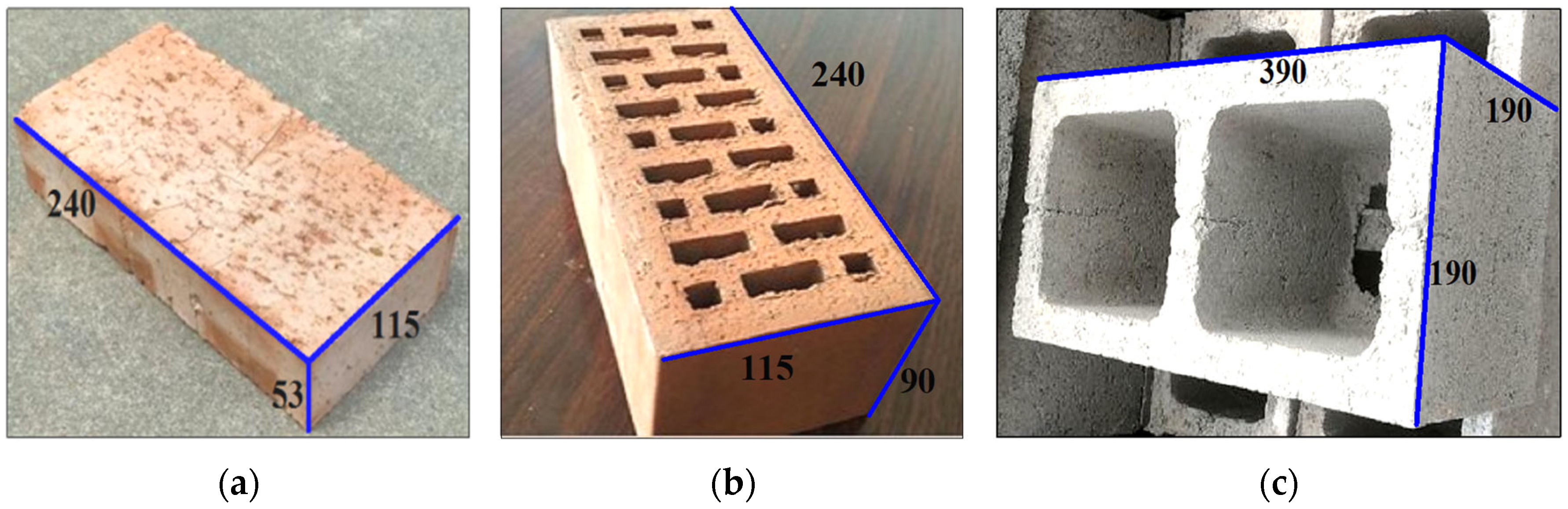
2.1. Mechanical Characteristics of Brick-Based Materials

This study investigates three of the most representative masonry materials commonly used in rural construction in China: solid clay bricks (SBs), fired perforated bricks (PBs), and concrete hollow blocks (HBs). SB: as a traditional masonry material, SB offers advantages such as simple production processes and low cost, having long dominated the rural construction market. PB: through optimized perforation design, PB maintains compressive strength while reducing material weight, aligning with the development trends of green building practices. HB: due to its prefabricated industrial nature, HB exhibits superior dimensional accuracy compared to fired bricks and significantly reduces clay consumption, making it a promising alternative to traditional fired bricks.
Standard specimen dimensions are illustrated in Figure 1. Mechanical parameter testing was conducted in strict accordance with GB/T 2542-2012 (Test Methods for Wall Bricks) [48] and GB/T 4111-2013 (Test Methods for Concrete Blocks and Bricks) [49]. Key indicators, including compressive strength and coefficient of variation (CoV), are summarized in Table 1.

2.2. Mechanical Properties of Fabric–Matrix Composites

This study employs knitted polyester grille (KPG) as the reinforcing fabric (Figure 2). The mesh aperture measures 25.4 mm × 25.4 mm, with a single fabric strand diameter of 2.1 mm. The warp-direction tensile strength of KPG exceeds 0.3 MPa, demonstrating superior performance compared to conventional fiberglass grids [50].
It is well-established that compatibility between fabric and matrix varies significantly across material combinations. Previous studies [51] confirm that KPG exhibits excellent interfacial bonding with cementitious matrices. The cementitious matrix in this study consists of cement, fine sand, fly ash, silica fume, and a superplasticizer, mixed with an appropriate proportion of tap water. The finalized mix design is presented in Table 2, while the corresponding mechanical properties of the matrix are summarized in Table 3.

3. Tensile Performance of Fabric and Reinforcement Systems

3.1. Tensile Properties of KPG Fabric

The KPG fabric, with a cross-sectional area of 3.46 mm2 per strand and uniform 25.4 mm spacing between warp and weft yarns (knitted in quadruple bundles), was tested exclusively along the warp direction to evaluate directional strength. Following the Round Robin testing protocols [53] and GB/T 3362-2017 (Test Methods for Tensile Properties of Carbon Fiber Multifilaments) [54], specially designed specimens (detailed in Figure 3) were prepared with 100 mm long fiber-reinforced polymer (FRP) plates, bonded at both ends to prevent stress concentration during gripping. Tensile tests were performed on a universal testing machine under displacement-controlled loading at 0.6 mm/min, with strain measurements obtained using a 100 mm gauge-length extensometer. The resulting tensile performance data are systematically presented in Table 4, providing characterization of the fabric’s mechanical behavior under uniaxial tension. σ, ε and E represent the tensile stress, tensile strain, and Young’s modulus of the fabric, respectively.

3.2. Tensile Performance of FRCM Strengthening System

Following the tensile testing guidelines for FRCM composites recommended in the literature [55], the strengthening system was designed with dimensions of 600 mm × 50 mm (length × width), as detailed in Figure 4. The composite system, with an average thickness of 10 mm, consisted of base and surface mortar layers with embedded-fabric reinforcement. Prior to embedding, the KPG fabric was pre-impregnated and subjected to slight manual pre-tensioning during fabrication, to maintain optimal flatness. Aluminum alloy plates were bonded at both ends to prevent premature failure caused by stress concentration at the gripping zones.
The FRCM installation procedure involved (i) applying the release agent on supporting pads and securing lower wooden formwork; (ii) casting the base mortar layer within the formwork; (iii) carefully pressing the fabric into the fresh mortar; (iv) installing upper formwork and casting the surface mortar layer; and (v) manually finishing the surface to achieve smoothness. The specimens were cured at ambient temperature for 28 days [56,57], with special attention given to potential microcracking from differential shrinkage. Such cracks were remedied by reapplying mortar slurry of identical mix proportions. The construction and curing are illustrated in Figure 5.

3.3. Crack Evolution in FRCM Strengthening System

Figure 6 illustrates the progressive crack development in the FRCM system, which exhibits three distinct failure phases: (i) uncracked stage, (ii) crack propagation stage, and (iii) rupture failure stage. During the initial uncracked stage, no surface cracking was observed, with the matrix contributing significantly to both load-bearing capacity and system stiffness. Upon exceeding the matrix tensile strength, the first crack typically initiated near the midspan region, accompanied by a marked reduction in system stiffness. The crack propagation stage was characterized by sequential formation of multiple cracks, including those beyond the extensometer measurement range. After reaching crack saturation, existing cracks progressively widened, ultimately exposing the embedded fabric reinforcement. Final failure occurred in the rupture stage, when tensile fracture of the fabric reinforcement precipitated complete system collapse. This three-stage failure mechanism demonstrates the sequential damage progression of the strengthening system: “matrix-dominated load-bearing—crack propagation and load transfer—fabric-dominated load-bearing—ultimate fracture failure”. The well-ordered failure process confirms the technical rationality of fabric-reinforced cementitious matrix (FRCM) composites as a viable alternative to conventional reinforcement materials.

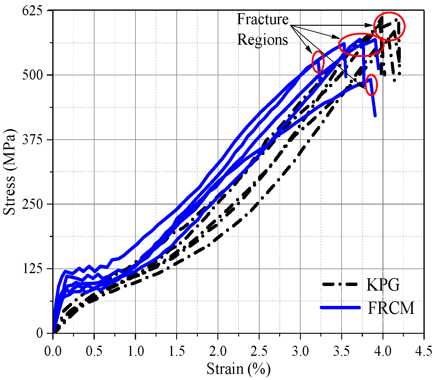
3.4. Stress–Strain Responses of Fabric and Strengthening System

Figure 7 presents the comparative stress–strain response curves obtained from uniaxial tensile testing of both the fabric and FRCM strengthening system, with corresponding quantitative results summarized in Table 5. The strengthening system consistently demonstrated marginally higher stress values than the standalone fabric, suggesting a measurable matrix contribution to the composite’s tensile resistance.
Three characteristic regimes were identified in the system’s mechanical response:
Pre-cracking Phase: the tensile behavior exhibited composite action, with both matrix and fabric sharing the applied stresses.
Post-cracking Phase: system stiffness underwent significant degradation upon initial matrix cracking, attributed to tensile hardening effects in the matrix between cracks [58].
Fabric-Dominated Phase: subsequent loading was resisted exclusively by the fabric reinforcement, evidenced by progressive crack widening until ultimate failure occurred at fabric rupture.
The experimental data confirm that while the matrix provides initial stiffness enhancement, the ultimate load-bearing capacity depends primarily on the fabric reinforcement characteristics. This transition in load-transfer mechanisms has important implications for the design of FRCM strengthening systems.

4. Experimental Design Details

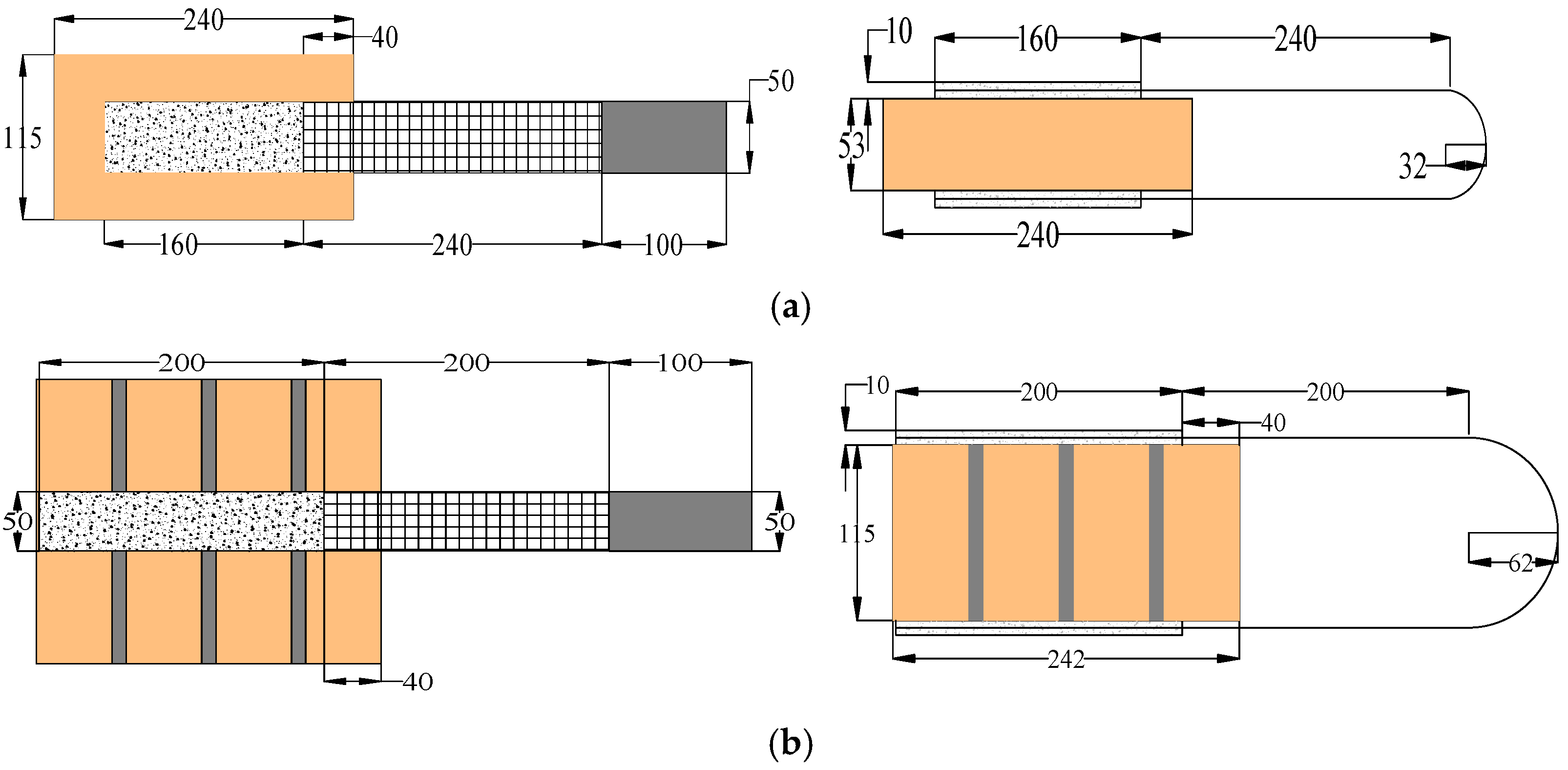
4.1. Specimen Design

Based on References [38,58,59,60,61], the bond lengths for brick substrate units and prisms were designed as 160 mm (for SB and PB substrates) and 200 mm (for HB substrates), respectively, with a uniform bond width of 50 mm. The unbonded lengths at the loading end were set at 40 mm for all specimens except HB prisms, which featured an 80 mm unbonded length.
This design methodology was implemented to systematically investigate (i) the influence of different brick substrate types (SB/PB/HB) on FRCM composite bond capacity and (ii) the effect of mortar joint presence/absence on composite bonding performance. Five replicate specimens were prepared for each test configuration. Detailed dimensional specifications are presented in Figure 8 (illustrating representative SB substrate specimens; PB/HB configurations follow analogous geometry, with adjusted bond lengths).

4.2. Specimen Nomenclature Convention

Specimens are designated using the nomenclature SB(PB/HB)-U(P)-S(D). SB-U-S: solid-brick unit under single-lap loading; HB-P-D: hollow-block prism under double-lap loading. Other designations follow analogous convention.

4.3. Specimen Fabrication

The prism specimens were constructed by experienced masons, using mortar with an average joint thickness of 10 mm, prepared with Type II Portland cement (maximum aggregate size 2 mm) at a 1:6:1 volumetric ratio of cement: fine sand: water [50]. Quality control testing per JGJ/T 223-2010 [52] on 70.7 mm3 mortar cubes yielded an average compressive strength of 8.92 MPa (CoV = 0.08), with all specimens undergoing 7-day moist curing followed by ambient-temperature conditioning (20 °C and 80% relative humidity) until testing, as documented in the fabrication process shown in Figure 9.

4.4. Test Setup

A specialized test setup was designed to accommodate both single-lap and double-lap shear test configurations. The system comprises two primary components: a rigid specimen fixation frame and modular loading-end adapters. For single-lap shear tests, the composite end of specimens was secured using corrugated rectangular steel plates before being mounted in the testing machine grips. Double-lap shear tests employed U-shaped steel connectors to engage the specimen’s semicircular ends, with subsequent fixation via base-mounted corrugated plates.
The apparatus components and assembly are detailed in Figure 10, with numerical annotations indicating the following: 1—top plate; 2—upper/lower corrugated plates; 3—base plate; 4—rigid threaded rods; 5—fastening nuts; 6—rectangular corrugated plate (single-lap); 7—U-shaped connector (double-lap); 8—steel guide sleeve; 9—steel dowel; 10—test specimen; 11—displacement transducer.

4.5. Instrumentation and Loading Protocol

The relative slip between the composite material and brick substrate was measured using paired displacement transducers, selected for their superior sensitivity and reliability in displacement monitoring. Each transducer was mounted with its fixed end secured to an aluminum plate attached to the exposed fabric reinforcement and its moving end anchored to the brick substrate surface, enabling direct measurement of interfacial slip displacement.
The tests employed displacement-controlled loading at a constant rate of 0.30 mm/min under uniaxial tension until failure. This loading rate was determined through comprehensive analysis of recommended rates (0.10–0.50 mm/min) [62] for bond characterization between composite materials and masonry substrates.

5. Analysis and Discussion of Bond Performance Test Results

The experimental investigation evaluated key bond performance parameters including debonding failure modes, global load-slip curves, failure loads, peak stresses, and composite utilization ratios.

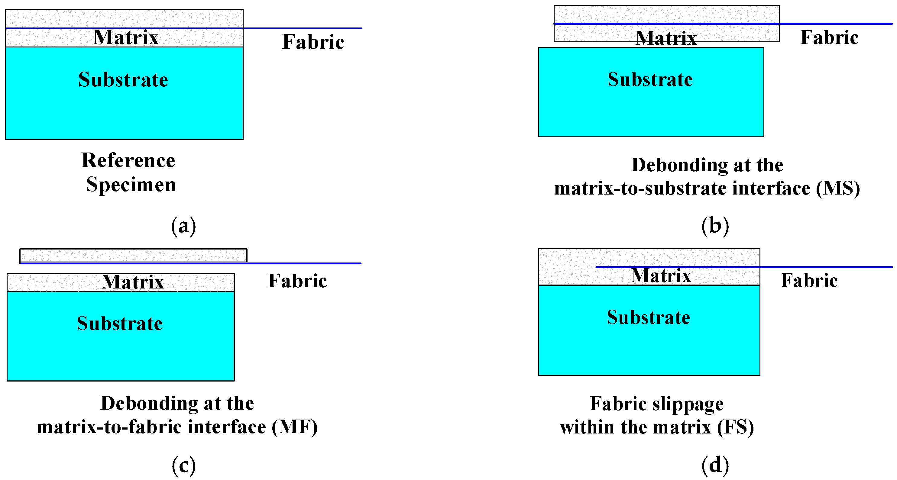
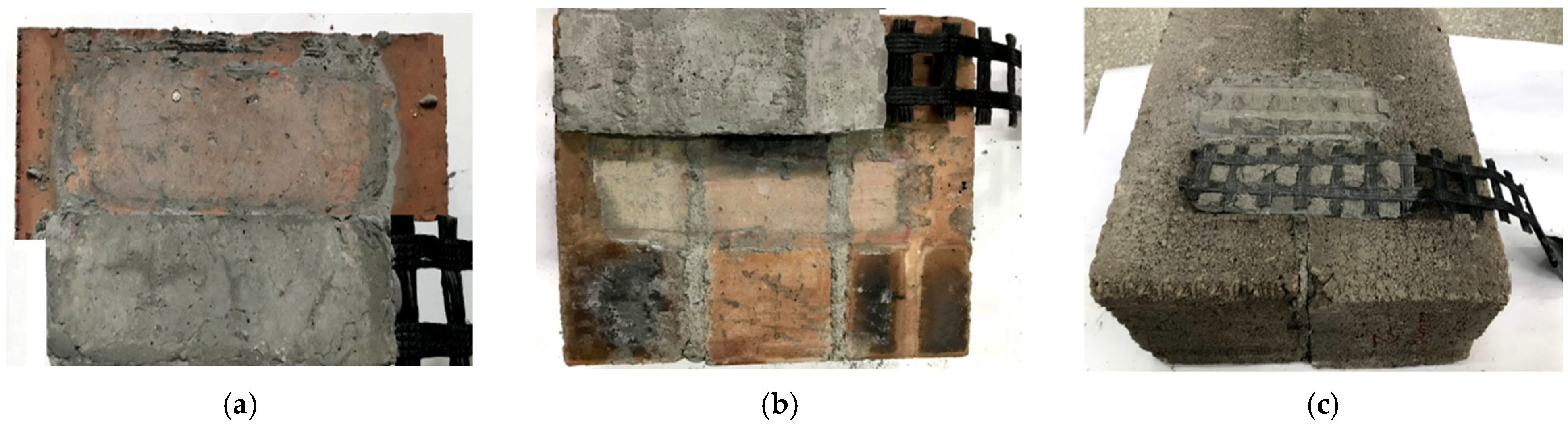
5.1. Characterization of Debonding Failure Modes

Figure 11 illustrates the characteristic failure modes observed at the FRCM composite–substrate interfaces, categorized as MS (matrix–substrate interfacial debonding), MF (matrix–fabric interfacial separation), and FS (fabric slippage within matrix). The predominant failure modes for each test group are systematically summarized in Table 6.
Figure 12 illustrates the predominant debonding failure modes observed during experimental testing, revealing substrate-dependent failure mechanisms. The MS failure occurred exclusively in PB brick substrates across all specimen configurations (Figure 12a,b), attributable to the brick’s smooth surface texture and micro-porosity, which hindered effective bonding, as evidenced by the absence of matrix cracking or fabric slippage post-debonding. In contrast, SB and HB substrates exhibited either MF or FS failures (Figure 12c–f), with the transition between these modes governed primarily by fabric–matrix interlock quality. Manual specimen fabrication introduced non-uniform vertical compaction pressure, where insufficient pressure led to MF failure (characterized by intact KPG–upper-matrix interfaces) while uniform pressure promoted FS failure (manifested as matrix striation parallel to weft yarns). Notably, the absence of substrate–matrix interfacial cracking in SB/HB specimens confirmed superior bond performance, with KPG’s high tensile strength preventing premature fabric rupture and allowing progressive matrix cracking, which demonstrated the FRCM system’s significant plastic deformation capacity.
The observed failure modes provide critical insights into FRCM system performance, highlighting the importance of substrate surface characteristics and manufacturing quality control. The PB substrates’ inherent limitations in bond formation contrasted sharply with the robust SB/HB matrix compatibility, while variations in compaction pressure during manual fabrication significantly influenced failure mode transitions between MF and FS types. These findings underscore the necessity for material-specific substrate preparation and standardized compaction protocols to ensure optimal interlock performance. The systematic documentation of failure characteristics offers valuable benchmarks for both bond quality assessment and practical application guidelines, meeting rigorous reporting standards while advancing understanding of FRCM-to-masonry bond behavior under different loading conditions and substrate configurations. The results emphasize the system’s deformation capacity, while identifying key parameters controlling interfacial failure mechanisms, providing a foundation for future research on standardized manufacturing processes and enhanced bond performance.

5.2. Global Load-Slip Behavior

Figure 13 presents the experimentally obtained global load-slip curves, where the load values were directly acquired from the universal testing machine and the global displacement represents the average of two displacement transducers mounted at the unbonded fabric region near the loading end. It should be noted that the single-lap and double-lap tests yielded comparable curve characteristics, and thus the analysis focuses exclusively on single-lap results. The comparative evaluation of failure loads and peak stresses between the two test configurations will be addressed in subsequent sections.
The global load-slip curves exhibit two distinct characteristics across all brick substrates: (i) all curves display fluctuating ascending patterns until failure, without pronounced linear phases, reflecting the fabric’s flexible tensile behavior due to its relatively low elastic modulus; (ii) prism specimens demonstrate more pronounced curve fluctuations compared to brick units, primarily attributable to the mechanical interlocking effect of mortar joints.
Detailed examination reveals substrate-specific behaviors: (i) PB prism specimens show significantly enhanced curve fluctuations and higher failure loads than PB units, resulting from increased interface roughness and frictional resistance induced by mortar joints; (ii) HB specimens exhibit minimal mortar joint effects due to compositional similarity between hollow blocks and joint mortar (cement–fine-sand–water system). Furthermore, larger fabric grid spacing contributes to increased interfacial slip, as the substantial yarn cross-section limits matrix penetration, resulting in predominantly surface-level bonding that reduces bond efficiency—a finding consistent with the existing literature [63].

5.3. Failure Load

The failure loads of composites with different brick substrates are summarized in Table 6. Both SB and HB substrates demonstrated comparable and significantly higher failure loads (4861–5873 N) compared to PB substrates (2796–3741 N), regardless of specimen configuration (units or prisms). This substantial performance variation primarily stems from distinct debonding failure mechanisms: FS (fabric slippage) and MF (matrix–fabric interfacial) failures dominated in SB and HB specimens, while MS (matrix–substrate interfacial) failure characterized PB specimens.

5.4. Peak Stress Analysis

The normal stress induced by applied loading serves as a critical parameter for shear testing [17]. In this section, Equation (1) was used to calculate the peak normal stress (σmax):
σ max = F max b t n
where Fmax represents the maximum applied load, bt denotes the fabric cross-sectional area, and n indicates the number of fabric strands along the warp direction. This normalization approach enables direct comparison of test results across varying bond widths [64].
As evidenced by the test results in Table 6, the bond performance of FRCM composites exhibits significant variations across the three brick substrates. The peak stresses follow this order: solid brick (144.11–155.95 MPa) > hollow block (133.91–149.48 MPa) > perforated brick (69.64–74.33 MPa). Notably, the peak stresses on solid bricks and hollow blocks are comparable, whereas those on perforated bricks are approximately 50% lower. This discrepancy may be attributed to substrate surface morphology: the perforated bricks’ smooth surface reduces the effective bonding area at the FRCM–substrate interface, while the rougher surfaces of solid bricks and hollow blocks enhance interfacial bonding through mechanical interlocking.
Furthermore, double-lap specimens generally demonstrate marginally higher peak stresses than single-lap ones (+2.4% for solid brick, +10.9% for hollow block, and +1.4% for perforated brick). This improvement likely stems from more uniform load distribution and reduced local stress concentration under double-lap loading. However, the underlying mechanisms—interfacial failure modes or fabric stress redistribution—require further investigation. Comprehensive characterization using scanning electron microscopy (SEM) for interface morphology examination combined with digital image correlation (DIC) techniques for strain field analysis would be essential to elucidate these phenomena.

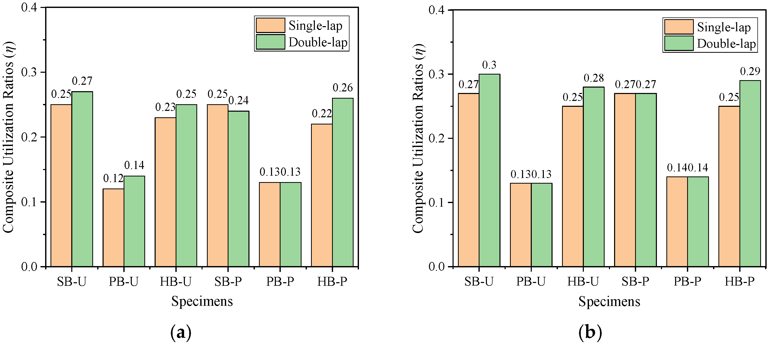
5.5. Composite Utilization Ratio

When evaluating bond performance test results, two key utilization ratios (η) must be considered, according to established definitions in Reference [63]: (1) fabric utilization ratio (VS fabric), calculated as the bond peak stress (σbond) divided by the fabric’s ultimate tensile stress (σfabric); and (2) system utilization ratio (VS system), determined by the bond peak stress relative to the system’s ultimate tensile stress (σfabric). The following formulas, (2) and (3), are used to calculate η(vs fabric) and η(vs system), respectively:
η vs   fabric = σ bond σ fabric
η vs   system = σ bond   σ system
As presented in Table 6 and Figure 14, the calculated utilization ratios reveal several important findings. Both fabric and system utilization ratios fell within the 12–30% range across all test configurations (single-/double-lap), showing no significant difference between the two metrics. This relatively low efficiency may be attributed to (i) limited bond strength at the brick substrate–matrix interface restricting full development of the fabric’s tensile capacity, and (ii) reduced bonding effectiveness for large cross-section fabrics, promoting fabric slippage within the matrix under tensile loading. Notably, PB substrates demonstrated the lowest utilization ratios, regardless of specimen configuration (units/prisms), directly correlating with their smooth surface characteristics. These results suggest that substrate surface roughness plays a critical role in minimizing interfacial debonding failures (MS mode), while fabric–matrix interlocking capability significantly influences the tensile performance of strengthening systems [17,65].

6. Conclusions

This study systematically investigated the bond behavior between FRCM composites and various brick substrates (SB, PB, HB) using knitted polyester grille (KPG) fabric. Through comprehensive testing of the fabric and strengthening system’s tensile mechanical response, as well as shear tests under both single-lap and double-lap loading configurations, the following key conclusions were drawn:
(1)
The FRCM strengthening system exhibited three distinct failure phases: uncracked, crack development, and rupture. Throughout all loading stages, the system demonstrated superior strength and stiffness compared to the fabric alone, despite their similar peak stress values.
(2)
Test setup (single-lap vs. double-lap) showed negligible influence on debonding failure modes. Specimens predominantly failed through either interfacial debonding or fabric slippage, with the transition between these modes governed by fabric–matrix interlock quality.
(3)
The presence of mortar joints significantly affected load-slip response curves, particularly in prism specimens, which exhibited more pronounced curve fluctuations compared to brick units across all loading conditions.
(4)
Both loading configurations produced comparable failure loads with low experimental variability, confirming the reliability of the designed test apparatus. Peak stresses showed strong dependence on debonding failure modes.
(5)
The FRCM system achieved 12–30% utilization efficiency for both fabric and composite system capacities. This constrained performance resulted from (i) dominant failure mode characteristics; and (ii) potential overdesign of fabric tensile capacity (requiring further verification).
(6)
Through comprehensive comparative analysis, concrete hollow blocks can achieve higher bonding performance and reasonable debonding failure modes in the renovation and repair process of actual engineering, and should be recommended as the most suitable substrate material. In addition, FRCM composite materials showed similar peak stress and failure modes in single-lap and double-lap tests. For areas where simultaneous construction of both sides of the wall is not possible, only the exterior wall can be used for construction, which can cooperate with the deformation of the brick substrate without generating additional stiffness.

Author Contributions

Methodology, software, investigation, writing—original draft, project administration, funding acquisition, P.M.; conceptualization, writing—review and editing, S.Y.; software, writing—original draft, S.J. All authors have read and agreed to the published version of the manuscript.

Funding

This research was funded by the Lanzhou Science and Technology Plan Project (grant No. 2024–9–302) and the Natural Science Foundation of China (grant No. 51978401).

Data Availability Statement

The original contributions presented in the study are included in the article; further inquiries can be directed to the corresponding authors.

Conflicts of Interest

The authors declare no conflicts of interest.

References

  1. GB 50011-2010; Code for Seismic Design of Buildings. China Architecture & Building Press: Beijing, China, 2010.
  2. Bagheri, B.; Lee, J.-H.; Kim, H.-G.; Oh, S.-H. Experimental Evaluation of the Seismic Performance of Retrofitted Masonry Walls. Compos. Struct. 2020, 240, 111997. [Google Scholar] [CrossRef]
  3. Marcari, G.; Manfredi, G.; Prota, A.; Pecce, M. In-Plane Shear Performance of Masonry Panels Strengthened with FRP. Compos. Part B Eng. 2007, 38, 887–901. [Google Scholar] [CrossRef]
  4. Zhou, D.; Lei, Z.; Wang, J. In-Plane Behavior of Seismically Damaged Masonry Walls Repaired with External BFRP. Compos. Struct. 2013, 102, 9–19. [Google Scholar] [CrossRef]
  5. Babatunde, S.A. Review of Strengthening Techniques for Masonry Using Fiber Reinforced Polymers. Compos. Struct. 2017, 161, 246–255. [Google Scholar] [CrossRef]
  6. NR-DT 200/2006; Guide for the Design and Construction of Externally Bonded FRP Systems for Strengthening Existing Structures. Materials, RC and PC Structures, Masonry Structures. National Research Council, Rome-CNR: Rome, Italy, 2006.
  7. Tetta, Z.C.; Bournas, D.A. TRM vs FRP Jacketing in Shear Strengthening of Concrete Members Subjected to High Temperatures. Compos. Part B Eng. 2016, 106, 190–205. [Google Scholar] [CrossRef]
  8. Raoof, S.M.; Bournas, D.A. Bond between TRM versus FRP Composites and Concrete at High Temperatures. Compos. Part B Eng. 2017, 127, 150–165. [Google Scholar] [CrossRef]
  9. Raoof, S.M.; Bournas, D.A. TRM versus FRP in Flexural Strengthening of RC Beams: Behaviour at High Temperatures. Constr. Build. Mater. 2017, 154, 424–437. [Google Scholar] [CrossRef]
  10. Papanicolaou, C.G.; Triantafillou, T.C.; Karlos, K.; Papathanasiou, M. Textile-Reinforced Mortar (TRM) versus FRP as Strengthening Material of URM Walls: In-Plane Cyclic Loading. Mater. Struct. 2007, 40, 1081–1097. [Google Scholar] [CrossRef]
  11. Papanicolaou, C.G.; Triantafillou, T.C.; Papathanasiou, M.; Karlos, K. Textile Reinforced Mortar (TRM) versus FRP as Strengthening Material of URM Walls: Out-of-Plane Cyclic Loading. Mater. Struct. 2007, 41, 143–157. [Google Scholar] [CrossRef]
  12. De Felice, G.; De Santis, S.; Garmendia, L.; Ghiassi, B.; Larrinaga, P.; Lourenço, P.B.; Oliveira, D.V.; Paolacci, F.; Papanicolaou, C.G. Mortar-Based Systems for Externally Bonded Strengthening of Masonry. Mater. Struct. 2014, 47, 2021–2037. [Google Scholar] [CrossRef]
  13. Razavizadeh, A.; Ghiassi, B.; Oliveira, D.V. Bond Behavior of SRG-Strengthened Masonry Units: Testing and Numerical Modeling. Constr. Build. Mater. 2014, 64, 387–397. [Google Scholar] [CrossRef]
  14. Kouris, L.A.S.; Triantafillou, T.C. State-of-the-Art on Strengthening of Masonry Structures with Textile Reinforced Mortar (TRM). Constr. Build. Mater. 2018, 188, 1221–1233. [Google Scholar] [CrossRef]
  15. Oliveira, D.V.; Basilio, I.; Lourenço, P.B. Experimental Bond Behavior of FRP Sheets Glued on Brick Masonry. J. Compos. Constr. 2011, 15, 32–41. [Google Scholar] [CrossRef]
  16. Mazzotti, C.; Savoia, M.; Ferracuti, B. A New Single-Shear Set-up for Stable Debonding of FRP–Concrete Joints. Constr. Build. Mater. 2009, 23, 1529–1537. [Google Scholar] [CrossRef]
  17. Ombres, L.; Mancuso, N.; Mazzuca, S.; Verre, S. Bond between Carbon Fabric-Reinforced Cementitious Matrix and Masonry Substrate. J. Mater. Civ. Eng. 2019, 31, 04018356. [Google Scholar] [CrossRef]
  18. Bui, T.-L.; Si Larbi, A.; Reboul, N.; Ferrier, E. Shear Behaviour of Masonry Walls Strengthened by External Bonded FRP and TRC. Compos. Struct. 2015, 132, 923–932. [Google Scholar] [CrossRef]
  19. De Santis, S.; de Felice, G. Tensile Behaviour of Mortar-Based Composites for Externally Bonded Reinforcement Systems. Compos. Part B Eng. 2015, 68, 401–413. [Google Scholar] [CrossRef]
  20. Shiping, Y.; Boxue, W.; Chenxue, Z.; Shuang, L. Bond Performance between Textile Reinforced Concrete (TRC) and Brick Masonry under Conventional Environment. Structures 2022, 36, 392–403. [Google Scholar] [CrossRef]
  21. Bilotta, A.; Ceroni, F.; Nigro, E.; Pecce, M. Experimental Tests on FRCM Strengthening Systems for Tuff Masonry Elements. Constr. Build. Mater. 2017, 138, 114–133. [Google Scholar] [CrossRef]
  22. Augenti, N.; Parisi, F.; Prota, A.; Manfredi, G. In-Plane Lateral Response of a Full-Scale Masonry Subassemblage with and without an Inorganic Matrix-Grid Strengthening System. J. Compos. Constr. 2011, 15, 578–590. [Google Scholar] [CrossRef]
  23. Balsamo, A.; Iovinella, I.; Di Ludovico, M.; Prota, A. Masonry Reinforcement with IMG Composites: Experimental Investigation. Key Eng. Mater. 2014, 624, 275–282. [Google Scholar] [CrossRef]
  24. Giamundo, V.; Lignola, G.P.; Maddaloni, G.; Balsamo, A.; Prota, A.; Manfredi, G. Experimental Investigation of the Seismic Performances of IMG Reinforcement on Curved Masonry Elements. Compos. Part B Eng. 2015, 70, 53–63. [Google Scholar] [CrossRef]
  25. Garmendia, L.; Larrinaga, P.; García, D.; Marcos, I. Textile-Reinforced Mortar as Strengthening Material for Masonry Arches. Int. J. Arch. Herit. 2014, 8, 627–648. [Google Scholar] [CrossRef]
  26. Ismail, N.; Ingham, J.M. In-Plane and out-of-Plane Testing of Unreinforced Masonry Walls Strengthened Using Polymer Textile Reinforced Mortar. Eng. Struct. 2016, 118, 167–177. [Google Scholar] [CrossRef]
  27. Giaretton, M.; Dizhur, D.; Garbin, E.; Ingham, J.M.; Da Porto, F. In-Plane Strengthening of Clay Brick and Block Masonry Walls Using Textile-Reinforced Mortar. J. Compos. Constr. 2018, 22, 04018028. [Google Scholar] [CrossRef]
  28. Donnini, J.; Maracchini, G.; Lenci, S.; Corinaldesi, V.; Quagliarini, E. TRM reinforced tuff and fired clay brick masonry: Experimental and analytical investigation on their in-plane and out-of-plane behavior. Constr. Build. Mater. 2021, 272, 121643. [Google Scholar] [CrossRef]
  29. De Santis, S.; Hadad, H.A.; De Caso, Y.; Basalo, F.; De Felice, G.; Nanni, A. Acceptance Criteria for Tensile Characterization of Fabric-Reinforced Cementitious Matrix Systems for Concrete and Masonry Repair. J. Compos. Constr. 2018, 22, 04018048. [Google Scholar] [CrossRef]
  30. Babaeidarabad, S.; Nanni, A. In-Plane Behavior of Unreinforced Masonry Walls Strengthened with Fabric- Reinforced Cementitious Matrix (FRCM). In SP-299: Fiber Reinforced Concrete for Sustainable Structures; American Concrete Institute: Farmington Hills, MI, USA, 2015. [Google Scholar]
  31. Alecci, V.; Focacci, F.; Rovero, L.; Stipo, G.; De Stefano, M. Extrados Strengthening of Brick Masonry Arches with PBO–FRCM Composites: Experimental and Analytical Investigations. Compos. Struct. 2016, 149, 184–196. [Google Scholar] [CrossRef]
  32. Alecci, V.; Focacci, F.; Rovero, L.; Stipo, G.; De Stefano, M. Intrados Strengthening of Brick Masonry Arches with Different FRCM Composites: Experimental and Analytical Investigations. Compos. Struct. 2017, 176, 898–909. [Google Scholar] [CrossRef]
  33. Grande, E.; Imbimbo, M.; Sacco, E. Investigation on the Bond Behavior of Clay Bricks Reinforced with SRP and SRG Strengthening Systems. Mater. Struct. 2015, 48, 3755–3770. [Google Scholar] [CrossRef]
  34. De Santis, S.; Casadei, P.; De Canio, G.; De Felice, G.; Malena, M.; Mongelli, M.; Roselli, I. Seismic Performance of Masonry Walls Retrofitted with Steel Reinforced Grout. Earthq. Eng. Struct. Dyn. 2016, 45, 229–251. [Google Scholar] [CrossRef]
  35. De Santis, S.; Ceroni, F.; De Felice, G.; Fagone, M.; Ghiassi, B.; Kwiecień, A.; Lignola, G.P.; Morganti, M.; Santandrea, M.; Valluzzi, M.R.; et al. Round Robin Test on Tensile and Bond Behaviour of Steel Reinforced Grout Systems. Compos. Part B Eng. 2017, 127, 100–120. [Google Scholar] [CrossRef]
  36. Wang, X.; Lam, C.C.; Iu, V.P.; Kou, K.P. Experimental and Analytical Investigation of Steel Reinforced Grout (SRG) Strengthened Masonry Panels. Key Eng. Mater. 2017, 747, 226–233. [Google Scholar] [CrossRef]
  37. Ekenel, M.; Basalo, F.D.C.Y.; Nanni, A. Acceptance Criteria for Concrete and Masonry Strengthening Using Fabric-Reinforced Cementitious Matrix (FRCM) and Steel Reinforced Grout (SRG) Composites. In Proceedings of the ACI Convention, 2017. [Google Scholar]
  38. Wang, X.; Lam, C.C.; Iu, V.P. Bond Behaviour of Steel-TRM Composites for Strengthening Masonry Elements: Experimental Testing and Numerical Modelling. Constr. Build. Mater. 2020, 253, 119157. [Google Scholar] [CrossRef]
  39. D’Antino, T.; Sneed, L.H.; Carloni, C.; Pellegrino, C. Influence of the Substrate Characteristics on the Bond Behavior of PBO FRCM-Concrete Joints. Constr. Build. Mater. 2015, 101, 838–850. [Google Scholar] [CrossRef]
  40. Subramaniam, K.V.; Carloni, C.; Nobile, L. Width Effect in the Interface Fracture during Shear Debonding of FRP Sheets from Concrete. Eng. Fract. Mech. 2007, 74, 578–594. [Google Scholar] [CrossRef]
  41. Dalalbashi, A.; Ghiassi, B.; Oliveira, D.V.; Freitas, A. Fiber-to-Mortar Bond Behavior in TRM Composites: Effect of Embedded Length and Fiber Configuration. Compos. Part B Eng. 2018, 152, 43–57. [Google Scholar] [CrossRef]
  42. ICC-ES AC 434; Acceptance Criteria for Masonry and Concrete Strengthening Using Fiber-Reinforced Cementitious Matrix (FRCM) Composite Systems. ICC-Evaluation Service: Whittier, CA, USA, 2013.
  43. ACI 549.4R-13; Guide to Design and Construction of Externally Bonded Fabric-Reinforced Cementitious Matrix (FRCM) Systems for Repair and Strengthening Concrete and Masonry Structures. American Concrete Institute: Farmington Hills, MI, USA, 2013.
  44. Sneed, L.H.; D’Antino, T.; Carloni, C.; Pellegrino, C. A Comparison of the Bond Behavior of PBO-FRCM Composites Determined by Double-Lap and Single-Lap Shear Tests. Cem. Concr. Compos. 2015, 64, 37–48. [Google Scholar] [CrossRef]
  45. Alecci, V.; Barducci, S.; Stefano, M.D.; Galassi, S.; Luciano, R.; Rovero, L.; Stipo, G. Reliability of Different Test Setups and Influence of Mortar Mixture on the Fabric-Reinforced Cementitious Matrix-to-Brick Bond Response. J. Test. Eval. 2021, 49, 4476–4495. [Google Scholar] [CrossRef]
  46. Barducci, S.; Alecci, V.; De Stefano, M.; Misseri, G.; Rovero, L.; Stipo, G. Experimental and Analytical Investigations on Bond Behavior of Basalt-FRCM Systems. J. Compos. Constr. 2020, 24, 04019055. [Google Scholar] [CrossRef]
  47. D’Antino, T.; Carloni, C.; Sneed, L.H.; Pellegrino, C. Matrix–Fiber Bond Behavior in PBO FRCM Composites: A Fracture Mechanics Approach. Eng. Fract. Mech. 2014, 117, 94–111. [Google Scholar] [CrossRef]
  48. GB/T 2542–2012; Test Methods for Wall Bricks. Standardization Administration of China: Beijing, China, 2012.
  49. GB/T 4111-2013; Test Methods for the Concrete Block and Brick. China Architecture & Building Press: Beijing, China, 2013.
  50. Ma, P.; Xin, R.; Yao, J. Assessment of Failure Mode and Seismic Performance of Damaged Masonry Structures Retrofitted with Grout-Injected Ferrocement Overlay Reinforcement (GFOR). Constr. Build. Mater. 2021, 305, 124778. [Google Scholar] [CrossRef]
  51. Zhou, F.; Chen, X.; Du, Y. Study on In-Plane Shear Behavior of CTRM Plate. J. Hunan Univ. Nat. Sci. 2021, 48, 39–46. Available online: https://www.cnki.com.cn/Article/CJFDTotal-HNDX202105005.htm (accessed on 1 July 2025).
  52. JGJ/T 223–2010; Technical Specification for Application of Ready-Mixed Mortar. Standardization Administration of China: Beijing, China, 2011.
  53. Valluzzi, M.R.; Oliveira, D.V.; Caratelli, A.; Castori, G.; Corradi, M.; de Felice, G.; Garbin, E.; Garcia, D.; Garmendia, L.; Grande, E.; et al. Round Robin Test for Composite-to-Brick Shear Bond Characterization. Mater. Struct. 2012, 45, 1761–1791. [Google Scholar] [CrossRef]
  54. GB/T 3362-2017; Test Methods for Tensile Properties of Carbon Fiber Multifilament. Standardization Administration of China: Beijing, China, 2017.
  55. RILEM. Technical Committee 232-TDT (Wolfgang Brameshuber) Recommendation of RILEM TC 232-TDT: Test Methods and Design of Textile Reinforced Concrete. Mater. Struct. 2016, 49, 4923–4927. [Google Scholar] [CrossRef]
  56. CEN EN 1015-2; Methods of Test for Mortar for Masonry—Part 2: Bulk Sampling of Mortars and Preparation of Test Mortars. European Committee for Standarization: Brussels, Belgium, 1998.
  57. CEN EN 196-1; Methods of Testing Cement—Part 1: Determination of Strength. European Committee for Standarization: Brussels, Belgium, 2005.
  58. Leone, M.; Aiello, M.A.; Balsamo, A.; Carozzi, F.G.; Ceroni, F.; Corradi, M.; Gams, M.; Garbin, E.; Gattesco, N.; Krajewski, P.; et al. Glass Fabric Reinforced Cementitious Matrix: Tensile Properties and Bond Performance on Masonry Substrate. Compos. Part B Eng. 2017, 127, 196–214. [Google Scholar] [CrossRef]
  59. Carozzi, F.G.; Bellini, A.; D’Antino, T.; de Felice, G.; Focacci, F.; Hojdys, Ł.; Laghi, L.; Lanoye, E.; Micelli, F.; Panizza, M.; et al. Experimental Investigation of Tensile and Bond Properties of Carbon-FRCM Composites for Strengthening Masonry Elements. Compos. Part B Eng. 2017, 128, 100–119. [Google Scholar] [CrossRef]
  60. Olivito, R.S.; Codispoti, R.; Cevallos, O.A. Bond Behavior of Flax-FRCM and PBO-FRCM Composites Applied on Clay Bricks: Experimental and Theoretical Study. Compos. Struct. 2016, 146, 221–231. [Google Scholar] [CrossRef]
  61. Grande, E.; Imbimbo, M.; Sacco, E. Bond Behaviour of CFRP Laminates Glued on Clay Bricks: Experimental and Numerical Study. Compos. Part B Eng. 2011, 42, 330–340. [Google Scholar] [CrossRef]
  62. Bellini, A.; Aiello, M.A.; Bencardino, F.; de Carvalho Bello, C.B.; Castori, G.; Cecchi, A.; Ceroni, F.; Corradi, M.; D’Antino, T.; De Santis, S.; et al. Influence of Different Set-up Parameters on the Bond Behavior of FRCM Composites. Constr. Build. Mater. 2021, 308, 124964. [Google Scholar] [CrossRef]
  63. Lignola, G.P.; Caggegi, C.; Ceroni, F.; De Santis, S.; Krajewski, P.; Lourenço, P.B.; Morganti, M.; Papanicolaou, C.; Pellegrino, C.; Prota, A.; et al. Performance Assessment of Basalt FRCM for Retrofit Applications on Masonry. Compos. Part B Eng. 2017, 128, 1–18. [Google Scholar] [CrossRef]
  64. Ma, P.; Xin, R.; Yao, J. An Investigation of Bond Behavior between Composite Materials (CFRP, GWMM, KPGC) and Substrates (Brick and Concrete) for Strengthening Existing Masonry Structures. Constr. Build. Mater. 2023, 409, 134019. [Google Scholar] [CrossRef]
  65. Ascione, L.; de Felice, G.; De Santis, S. A Qualification Method for Externally Bonded Fibre Reinforced Cementitious Matrix (FRCM) Strengthening Systems. Compos. Part B Eng. 2015, 78, 497–506. [Google Scholar] [CrossRef]
Figure 1. Brick substrate (dimensions in mm): (a) SB; (b) PB; (c) HB.
Jcs 09 00407 g001
Figure 2. Knitted polyester grille (mm).
Jcs 09 00407 g002
Figure 3. Dimensional specifications of test fabric (mm).
Jcs 09 00407 g003
Figure 4. Dimensional details of FRCM strengthening system (mm).
Jcs 09 00407 g004
Figure 5. Construction and curing processes of FRCM system: (a) construction; (b) curing.
Jcs 09 00407 g005
Figure 6. Crack evolution in FRCM strengthening system: (a) uncracked stage; (b) first crack; (c) crack propagation stage; (d) rupture failure stage.
Jcs 09 00407 g006
Figure 7. Stress–strain response curves of fabric and strengthening systems.
Jcs 09 00407 g007
Figure 8. Dimensional specifications of unit and prism specimens (mm): (a) SB-U-S and SB-U-D; (b) SB-P-S and SB-P-D.
Jcs 09 00407 g008
Figure 9. Schematic illustration of prism specimen fabrication and curing process: (a) SB-prism; (b) PB-prism; (c) HB-prism; (d) curing of bonded specimens.
Jcs 09 00407 g009aJcs 09 00407 g009b
Figure 10. Test setup: (a) component configuration for single-lap and double-lap setups; (b) integration assembly.
Jcs 09 00407 g010
Figure 11. Debonding failure modes of FRCM composites at substrate interfaces: (a) reference specimen; (b) MS; (c) MF; (d) FS.
Jcs 09 00407 g011
Figure 12. Characteristic debonding failure modes of test specimens: (a) PB-U-S; (b) PB-P-S; (c) HB-P-S; (d) SB-P-D; (e) SB-U-S; (f) HB-U-D.
Jcs 09 00407 g012aJcs 09 00407 g012b
Figure 13. Global load-slip curves of single-lap shear specimens: (a) SB-U-S; (b) SB-P-S; (c) PB-U-S; (d) PB-P-S; (e) HB-U-S; (f) HB-P-S.
Jcs 09 00407 g013aJcs 09 00407 g013b
Figure 14. Composite utilization ratios: (a) utilization ratios of fabric; (b) utilization ratios of system.
Jcs 09 00407 g014
Table 1. Mechanical properties of brick-substrate materials.
CategoryDimensions (mm)Compressive StrengthTesting Standard
Length × Width × HeightMean (MPa)(CoV)
SB240 × 115 × 5314.380.18GB/T 2542-2012 [48]
PB240 × 115 × 9012.870.13GB/T 2542-2012 [48]
HB390 × 190 × 1903.130.15GB/T 4111-2013 [49]
Table 2. Mix design proportions of matrix material (by weight ratio).
MatrixCementFine SandWaterFly AshSilica FumeSuperplasticizer
Cementitious matrix11.50.350.120.060.01
Table 3. Fundamental mechanical properties of matrix material.
MatrixCompressive StrengthElastic ModulusTesting Standard
Mean (MPa)(CoV)Mean (MPa)(CoV)
Cementitious matrix25.730.1138550.13JGJ/T 223-2010 [52]
Table 4. Tensile test results of fabric (the cross-sectional area of the fabric: bt = 3.46 mm2).
Fabricσ (MPa)ε (%)E (GPa)n
KPG596.54 (0.11)4.07 (0.07)18.13 (0.12)8
Table 5. Tensile test results of FRCM strengthening system (data in parentheses, CoV).
Strengthening SystemPre-Cracking PhasePost-Cracking PhaseFabric-Dominated Phase
σI (Mpa)εI (%)EI (Gpa)σII (Mpa)εII (%)EII (Gpa)σIII (Mpa)εIII (%)EIII (Gpa)
FRCM88.240.1367.34148.741.136.22543.333.6515.66
(0.16)(0.11)(0.29)(0.17)(0.21)(0.10)(0.07)(0.08)(0.13)
Where the symbols σ, ε, and E, respectively, represent the fabric’s tensile stress, tensile strain, and Young’s modulus, while the Roman numeral subscripts (I, II, III) denote distinct testing phases corresponding to pre-cracking, post-cracking, and fabric-dominated phase.
Table 6. Summary of experimental test results.
SpecimensFailure LoadFailure DisplacementPeak StressComposite Utilization RatioDebonding Failure Modes
(N)(mm)(MPa)VS FabricVS System
SB-U-S5700.144.06146.800.250.27FS
PB-U-S3170.061.9369.640.120.13MS
HB-U-S4998.623.74135.160.230.25FS
SB-P-S4861.604.05146.260.250.27MF + FS
PB-P-S3741.092.0473.690.130.14MS
HB-P-S5038.553.71133.910.220.25MF + FS
SB-U-D5817.634.32155.950.270.30FS
PB-U-D2796.511.9670.940.140.13MS
HB-U-D5873.614.12148.850.250.28FS
SB-P-D4934.713.99144.110.240.27MF + FS
PB-P-D3060.182.0674.330.130.14MS
HB-P-D4999.764.14149.480.260.29MF + FS
Disclaimer/Publisher’s Note: The statements, opinions and data contained in all publications are solely those of the individual author(s) and contributor(s) and not of MDPI and/or the editor(s). MDPI and/or the editor(s) disclaim responsibility for any injury to people or property resulting from any ideas, methods, instructions or products referred to in the content.

