Article

Replacing Glass with Basalt in the Vacuum Infusion Process of Vinyl Ester Composite Laminates: Effect on the Mechanical Performance and Life Cycle Assessment (LCA) †

Department of Engineering, University of Messina, Contrada di Dio (S. Agata), 98166 Messina, Italy
*
Author to whom correspondence should be addressed.
This paper is an extended version of our paper published in Totaro, M.; Risitano, G.; Di Bella, G.; Crisafulli, D.; D’Andrea, D. A Comparative Study on Mechanical Properties and Failure Mechanisms in Basalt and Glass Fibre Reinforced Composites. Procedia Structural Integrity 2024; 66: 205-211. 8th International Conference on Crack Paths—Rimini (CP 2024), Italy, 10–12 September 2024, Code 205571.
J. Compos. Sci. 2025, 9(6), 308; https://doi.org/10.3390/jcs9060308
Submission received: 7 May 2025 / Revised: 29 May 2025 / Accepted: 6 June 2025 / Published: 18 June 2025
(This article belongs to the Section Composites Applications)

Abstract

:
The increasing demand for environmentally friendly materials has driven researchers and industries to explore alternatives that combine performance with reduced environmental impact. In this framework, the possibility of replacing glass-fibre-reinforced composites (GFRCs) with basalt-fibre-reinforced composites (BFRCs) is attracting increasing attention. In this study, basalt–vinyl ester specimens and glass–vinyl ester specimens were mechanically characterized using both the Risitano Thermographic and Static Thermographic Methods. The results indicate that energy methods are effective for the mechanical characterization of complex materials like basalt and glass fibre composites. The average ultimate tensile strength was 374 ± 20.2 MPa for BFRCs and 295 ± 4.7 MPa for GFRCs, showing a 26.7% improvement with basalt. The fatigue limit was 96.5 ± 0.2 MPa for BFRCs and 104.8 ± 0.8 MPa for GFRCs, while the static stress limit estimated via thermography was 99.9 ± 6.45 MPa and 101.7 ± 5.24 MPa, respectively. Furthermore, the failure mechanisms of both BFRC and GFRC specimens were investigated. Additionally, a Life Cycle Assessment (LCA) was performed to evaluate the environmental impact of basalt and glass fibre composites. The results showed that BFRCs have lower environmental impacts, including 0.67 kg CO2-eq with respect to climate change versus 0.81 kg CO2-eq for GFRCs. This work highlights how the two materials are comparable in terms of their mechanical performance but different in terms of their sustainability and environmental impact.

1. Introduction

In recent decades, the rising demand for materials that offer a combination of high mechanical strength and lightweight properties has significantly accelerated the development of advanced fibre-reinforced composite materials. This demand stems from the need to create solutions that improve efficiency and performance across industries such as the aerospace, automotive, construction, and renewable energy industries and create eco-sustainable solutions [1,2,3]. By reducing weight while maintaining or even enhancing structural integrity, these materials allow for greater fuel efficiency, lower emissions, and increased durability in harsh environments. Consequently, the focus on fibre-reinforced composites has expanded, leading to innovations in material composition and processing techniques, as well as the exploration of new fibre types, such as basalt [4], hemp [5,6], and flax [7,8], that offer unique benefits in terms of sustainability and mechanical performance. Among these new fibre types, basalt fibres have gained particular attention due to their advantageous combination of mechanical properties, thermal stability [9], and environmental benefits [10]. Derived from volcanic rock, basalt fibres are produced through the application of spinneret technology to the molten raw material, similar to the production of traditional glass fibres [11], without the need for additional chemicals, making them an environmentally friendly alternative to traditional synthetic fibres. Thanks to their high tensile strength and excellent chemical and thermal resistance, but mostly their greater sustainability [10,12,13], basalt fibres are increasingly replacing glass fibres in many industrial applications, such as aerospace [14], automotive [15], and construction and civil engineering [16] applications, as well as other fields [17,18,19], where resistance to harsh environmental conditions and sustainability are crucial aspects. Compared with the widely used E-glass fibres, basalt fibres offer advantages in terms of their mechanical properties and environmental aspects. Although both fibre types share similar densities, basalt fibres exhibit higher tensile and compressive strength, as well as improved chemical and corrosion resistance [20]. Vashıshtha and Sharma [21] compared the quasi-static and dynamic impact loads of glass and basalt high-performance fibres in woven fabric-reinforced composites with thermoplastic and thermoset matrices, emphasizing the superior flexural properties of thermoplastic-based basalt composites over glass. Lopresto et al. [22] investigated the possibility of replacing glass fibres in most of their applications, evaluating the mechanical properties of E-glass- and basalt-fibre-reinforced plastic laminates. Their study showed that the basalt material had a high performance in terms of its Young’s modulus, compressive and bending strength, impact force, and energy. Meanwhile, Agrawal et al. [23] compared the tensile and fatigue behaviour of unidirectional glass fibre/epoxy (GFRP) and basalt fibre/epoxy (BFRP) composites and showed that both GFRPs and BFRPs have very similar tensile behaviour, whereas BFRPs perform better than GFRPs in terms of their fatigue life and degradation of properties. Despite these benefits, the cost of basalt fibres remains higher than that of E-glass, which has limited their widespread adoption in cost-sensitive industries. However, as manufacturing processes for basalt fibres continue to advance, production costs are expected to decrease, making them an increasingly viable option for a broader range of applications. The aim of this study was to conduct a comprehensive comparison of the static and fatigue behaviour of basalt and glass fibre composites through the application of energy methods, in particular the Static Thermographic Method (STM) and the Risitano Thermographic Method (RTM). In terms of tensile strength, experimental tests showed an average of 374 ± 20.2 MPa for basalt fibre composites and 295 ± 4.7 MPa for glass fibre composites, indicating a +26.7% increase with basalt. The fatigue limit was 96.5 ± 0.2 MPa for BFRCs and 104.8 ± 0.8 MPa for GFRCs. In addition to assessing their performance under static and fatigue loads, the study also explored the distinct failure mechanisms exhibited by basalt and glass fibre composites. This dual focus on both performance and failure modes provides a holistic understanding of these materials, supporting their potential applications in areas where long-term reliability and endurance are critical. Furthermore, a numerical analysis was conducted to compare the elastic behaviour of both composites with the results of experimental tests. Finally, a Life Cycle Assessment (LCA) was conducted to compare the sustainability of glass and basalt fibre composites. This LCA focused on assessing the environmental impact of each composite up to the production stage. These observations contribute to a better understanding of the sustainability potential of basalt fibre composites and their suitability as eco-friendly alternatives in various industrial applications. The use of LCA extends to numerous sectors, including the automotive [24], naval [25], and aerospace sectors [26], among others. The increasing attention devoted to environmental sustainability in materials research calls for a shift toward broader, system-level evaluations. In this context, the findings reaffirm the relevance of basalt-fibre-reinforced composites (BFRCs), which not only exhibit mechanical and environmental performance on par with or in some respects superior to traditional glass-fibre-reinforced composites (GFRCs), but also display favourable failure behaviours that are particularly valuable from a structural design standpoint. These attributes position BFRCs as promising candidates to progressively phase out GFRCs in several application domains.

2. Theoretical Background

Risitano was the first researcher to apply infrared thermography for assessing material fatigue in 1986 [27]. Later, in 2000, La Rosa and Risitano introduced the Thermographic Method, which enabled the rapid estimation of a material fatigue life [28]. RTM has since been widely adopted and further developed by many researchers [29,30,31]. The RTM involves determining the stabilization temperature corresponding to the stress level applied to the specimen. The surface temperature evolution can be divided into three distinct phases: in the first phase, the temperature rises until it reaches a stabilization point. During the second phase, the temperature remains constant at its stabilization value, ΔTst. In the third phase, the temperature begins to rise again before the specimen ultimately fails. The energy parameter, ϕ, can be determined as the area under the curve representing the temperature variation over the number of cycles, N (expressed in cycles∙K). Observations indicate that as the applied stress increases, the stabilization temperature also increases. However, the energy parameter remains nearly constant regardless of the applied stress, according to the following relationship:
Φ = Ni ΔTst
The fatigue limit is ultimately estimated as the stress level corresponding to a negligible increase in temperature (ΔTst∼0 K). The STM is based on the evolution of the temperature trend (dash-dot line) during a static tensile test (Figure 1). As observed by Risitano and Risitano [32], the thermal behaviour of a material under static tensile load is divided into three thermal phases. In the first phase, a linear cooling of the surface temperature is observed due to the thermoelastic effect, as formulated by Lord Kelvin:
Δ T s = α ρ · c T 0 · σ 1 = K m T 0 · σ 1
In this equation, ΔTs represents the surface temperature change, α is the coefficient of thermal expansion, ρ is the material density, σ1 is the principal applied stress, T0 is the absolute temperature of the material, and c is its specific heat capacity at constant pressure. Km is the thermoelastic constant. In the second phase, a deviation from the initial linear trend is observed, which is caused by the onset of early microdamage, until a minimum temperature is reached at the material yield stress (σy). In the third phase, there is an exponential increase in temperature until the material ultimately fails. The limit stress (σlim) can be estimated as the stress corresponding to the point at which the slope occurs between the first and second phase.

3. Materials and Methods

3.1. Specimens Preparation

For this study, two fibre-reinforced composite panels (1 m × 1 m) were sourced from Intermarine, a shipyard based in Sarzana, Italy. The distinguishing feature between the two lay in the nature of their reinforcements: one integrated traditional E-glass fibres, while the other employed continuous basalt fibres. Each panel was manufactured with six plies of woven fabric, resulting in an overall areal weight of 1100 g/m2. The basalt reinforcement was based on FILAVATM fibres (ISOMATEX S.A., Gembloux (Les Isnes), Belgium), processed into a Panama-style double weave to optimize mechanical interlocking. Conversely, the glass fibre fabric adhered to a more conventional weaving scheme typical of marine-grade composites. As the polymeric matrix, a low-viscosity vinyl ester resin Atlac® 580 AC 300 (AOC Italia S.r.l., Filago, Italy) was adopted, catalyzed with NOROX® (United Initiators GmbH, Pullach, Germany). This resin is engineered to perform under harsh marine conditions, offering a reliable balance between mechanical strength and moisture resistance. Its processing behaviour—particularly its compatibility with vacuum infusion techniques—ensured uniform impregnation and defect-free consolidation across the laminates. A summary of the material specifications is provided in Table 1 and Table 2.
The composite panels were manufactured via vacuum infusion, a closed-mould process depicted in Figure 2a. In this method, a vacuum is applied to draw the resin through the fibre stack, promoting uniform distribution and deep impregnation of the reinforcement layers. This technique not only minimizes the risk of void formation but also enhances the overall quality of the laminate, leading to improved mechanical properties and structural reliability. The process involves two key steps:
  • Layering of the Composite: The individual layers of glass or basalt fibres are carefully arranged in the desired lamination sequence. For this study, the sequence consisted of alternating orientations of fabric layers to optimize mechanical properties.
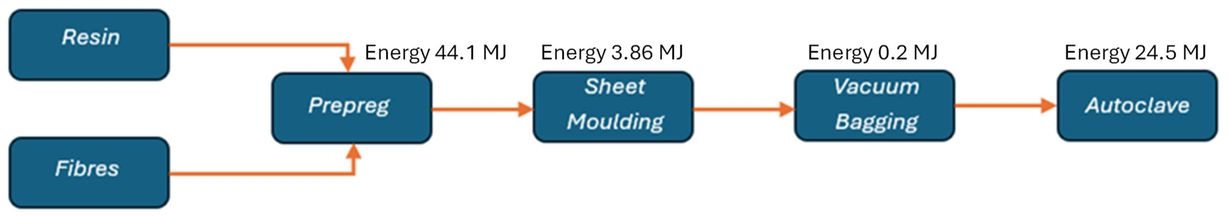
  • Vacuum Infusion: A vacuum bag is placed over the laminate stack, and resin is introduced into the system under vacuum. The resin permeates through the fibre layers, bonding them together and ensuring uniform resin distribution across the panel. The infusion process took place at room temperature, allowing for full resin penetration through the core and adequate adhesion between layers.
Vacuum infusion was selected for its proven capacity to yield high-performance laminates, characterized by improved flexural behaviour, increased stiffness, and a reduced presence of voids—factors closely linked to higher fibre volume fractions. The panels obtained through this method (Figure 2b,c) show excellent structural cohesion, making them particularly suitable for application in internal non-structural bulkheads within marine environments. Additionally, the closed-mould nature of the process contributes to lower emissions of volatile organic compounds (VOCs), supporting a more environmentally responsible manufacturing approach. Within Intermarine’s current production framework, glass fibre laminates are commonly adopted for such internal components. The motivation to explore basalt as an alternative stems from its comparable mechanical properties, paired with a more favourable environmental profile. Figure 3 presents close-up views of the basalt and glass fibre specimens captured under a Leica M165 FC optical microscope. The basalt fibres exhibit a coarser texture and a more defined weave geometry, suggesting increased robustness. In contrast, the glass fibres appear finer and show a less prominent woven structure, indicative of differences in fibre morphology and interlacing density.

3.2. Experimental Tests

The experimental tests consist of static tensile and stepwise fatigue tests, according to the ASTM D 3039/D 3039M standard. During the tests, the surface temperature of the specimen was monitored using an infrared camera, FLIR SC640. Five static tensile tests per material were performed under displacement control, with a crosshead speed of 2 mm/min, using a servo-hydraulic loading machine MTS 810, as shown in Figure 4, with a maximum load capacity of 250 kN. In applying the RTM, 2 stepwise fatigue tests per material were performed using the same loading machine with a stress ratio of R = 0.1 and a testing frequency of 10 Hz. Each step consisted of ΔN = 20.000 cycles, with the load being increased by Δσ = 10 MPa at each step, continuing until failure. A summary of the test configurations is provided in Table 3.

3.3. Thermal Analysis Methodology

Usually, to apply the STM, the maximum value of a rectangular area selected on the specimen is recorded and processed using a rlowess filter. This approach works well for most materials, where the point of maximum stress remains constant throughout the entire test, and failure starts from that point. However, when the same method was applied to composites, the signal was much more disturbed. This is because the maximum damage, corresponding to the hottest point, occurred at random locations that continuously shifted during the test. To address the difficulties encountered in signal analysis, a new data processing approach was developed. This approach is based on a statistical analysis aimed at identifying the five points on the specimen’s surface that are most stressed during the test. Specifically, the idea is to determine which five “spots” are the hottest on the surface most frequently during Phases I and II, and to calculate how often, in percentage terms, these points appear as the hottest. Typically, these five points are located relatively close to each other on the specimen’s surface and tend to concentrate near the clamping areas. Once these points are identified, the area enclosing them is selected, and the maximum temperature value within this zone is plotted. This approach allows for focusing on the most critical areas of the specimen, enhancing the detection of thermo-mechanical behaviour during the test. The disturbed signal, on the other hand, does not occur in the application of RTM, where the maximum temperature on the specimen’s surface is evaluated as prescribed by the method.

3.4. LCA Goal and Scope Definition

This study included a comparative analysis of the environmental impacts of vinyl ester resin composites reinforced with glass and basalt fibres. The primary aim was to quantify and compare the environmental loads associated with their production, identifying the most sustainable option. LCA follows a “cradle-to-gate” approach and applies the cut-off method, where no credits are given for recycled material unless it is recycled within the product system. Consequently, recyclable materials only bear the costs of the recycling process when they are recycled, with no additional charges for the recycling itself. When available, recyclable materials were sourced from the Italian market, otherwise from the European market. These materials included all upstream burdens, such as the average transportation of the product within the geographical area and the inputs needed to compensate for losses during trade and transport [33]. The functional unit defined for this study was the creation of a single specimen. The data for this analysis were derived from a combination of technical information (primary data) and literature integration (secondary data), providing a solid basis for the analysis. The analysis was performed using the OpenLCA software (GreenDelta, version 2.1.1), integrated with the Ecoinvent database (version 3.10, released in 2024). This methodology aligned with the international standards ISO 14040 and ISO 14044, providing a rigorous and structured methodological framework for conducting LCA studies [34].

3.5. Life Cycle Inventory

During the life cycle inventory phase, data regarding the inputs and outputs associated with the production of composites reinforced with basalt and glass fibres, using vinyl ester resin, were systematically collected. This analysis included the quantification of raw materials and the emissions generated during the production process. For modelling the production of basalt fibres, which is not available in the Ecoinvent database, the specific study [35] was referenced. Table 4 illustrates the details of the materials and energy required for the production of 1 kg of basalt fibres. For glass fibres and vinyl ester resin, production data were directly obtained from the Ecoinvent database. Figure 5 shows the block diagrams developed on OpenLCA for the production of the composites.
The energy required for the vacuum bagging process was obtained by consulting the study [36], which describes the production of 1 kg of composite. The block diagram of the energy needed for this process is shown in Figure 6.
The data were scaled based on the specific quantities used in the production of the composites.

4. Results

4.1. Static Characterization

Figure 7a,b illustrate the tensile stress–strain responses for the basalt- and glass-fibre-reinforced composites, respectively. Given the high repeatability of the experimental data, each graph presents a single, representative curve for clarity. In the case of the BFRC (Figure 7a), the curve does not follow a smooth, monotonic path. Instead, an initial load drop is observed, followed by a more significant decline at 374 MPa, corresponding to the onset of delamination—a critical failure event in this material system.
By contrast, the tensile response of the GFRC (Figure 7b) is markedly brittle, displaying a linear progression up to a sudden rupture occurring at approximately 295 Mpa. Notably, the initial load drop in the BFRC appears around 270 Mpa, which is lower than the ultimate strength recorded for the GFRC. However, the BFRC outperforms its counterpart in terms of ductility and energy absorption, offering a more gradual and damage-tolerant failure profile.
In this analysis, the tensile strength of the BFRC is defined by the stress level at which the first delamination occurs, with earlier fluctuations interpreted as indicators of incipient internal damage. The tensile strength values for both composites, averaged over five specimens per material, are summarized in Table 5. These contrasting behaviours are closely tied to the underlying failure mechanisms, which are further investigated through infrared thermographic analysis in Section 4.3.
The applied stress is plotted versus the filtered temperature signal in Figure 8a,b for both the BFRC and GFRC. Again, one representation is reported for each case. For the BFRC, the delamination instant was chosen to synchronize the temperature and load data. In the initial portion of the ΔT vs. time curve (Phase 1), a clear linear trend can be observed. This is followed by a deviation from linearity (Phase 2), where the slope varies depending on the case. Subsequently, the temperature rises steadily until failure. Two linear regression lines can be drawn, one for Phase 1 and one for Phase 2, and their equations determined. Solving these equations yields the coordinates of their intersection point. The value of limit stress evaluated with STM is 99.9 ± 6.45 Mpa for the BFRC and 101.7 ± 5.24 Mpa for the GFRC.

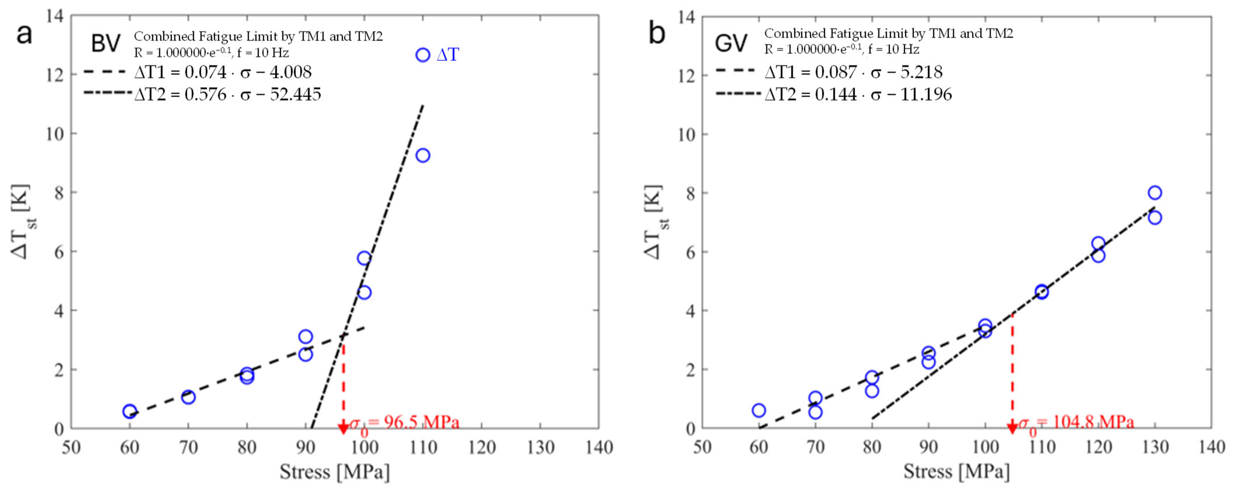
4.2. Fatigue Characterization

To compare the stress limit with the fatigue limit, two stepwise fatigue tests were conducted for each material, demonstrating excellent repeatability using the RTM.
Figure 9 presents the temperature evolution vs. the applied stress level. For each stress level, the corresponding stabilization temperature was determined. It was observed that for the BFRC, the temperature does not stabilize when the stress increases from 110 MPa to 120 MPa (Figure 9a), continuing to rise until the specimen fails. Similarly, for the GFRC, this instability occurs during the transition from 130 MPa to 140 MPa (Figure 9b). It is observed that, under equal loads, the thermal response of the two materials is different. In particular, basalt exhibits more pronounced heat increases because delamination occurs before failure. This delamination releases heat, contributing to more significant temperature deltas.
By plotting the stabilization temperature against the corresponding stress level (Figure 10a,b), a clear bilinear trend emerges. Linear regression was performed on the lower and upper datasets, and their intersection was used to determine the fatigue limit at R = 0.1 using the TM approach. The results indicate a fatigue limit of 96.5 ± 0.2 MPa for the BFRC and 104.8 ± 0.8 MPa for the GFRC.
Notably, the stress limit determined through STM falls within a similar range to that observed in traditional fatigue testing. These findings highlight that STM can serve as a reliable method for estimating the fatigue limit, even in composite materials. A summary of the fatigue results for the GFRC and BFRC is presented in Table 6, based on two tests per material.

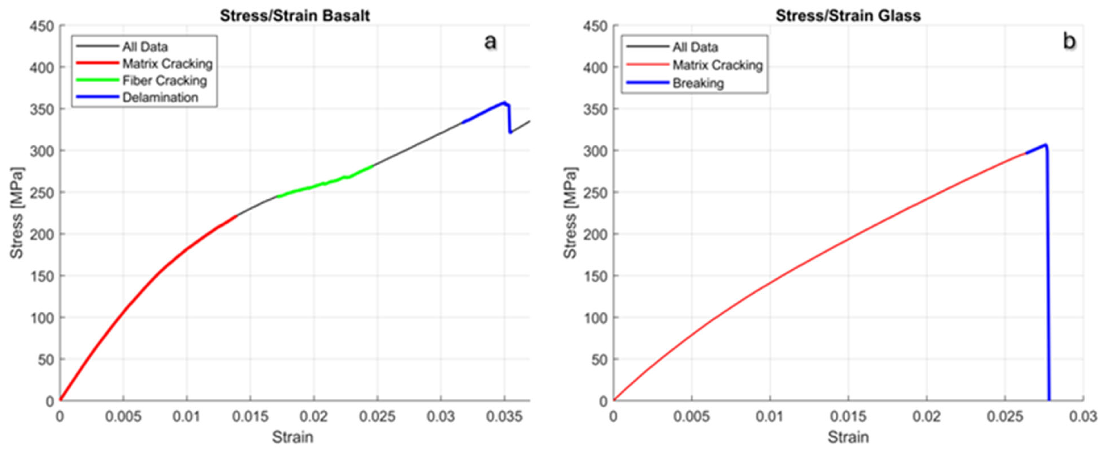
4.3. Tensile Failure Analysis

Two distinct failure mechanisms were identified during tensile testing: one primarily involving the cracking of the polymer matrix and the other associated with different modes of fibre failure. These damage modes were investigated through infrared thermography, which enabled real-time visualization and differentiation based on thermal signatures. The thermal maps use a colour scale from deep purple to bright yellow, where warmer colours correspond to localized increases in temperature associated with damage evolution.
In the red-highlighted segments of the stress–strain curves in Figure 7a,b, matrix cracking emerges as the dominant failure process, characterized by the appearance of sporadic high-temperature spots on the specimen’s surface. These localized heat spikes, shown as pale violet areas in Figure 11a (basalt fibres) and Figure 11b (glass fibres), develop progressively as the material deforms. Given that both composites share the same resin system, the matrix behaviour is broadly comparable. However, it is the fibre architecture and failure behaviour that drive the key differences in global mechanical response.
For the basalt-fibre-reinforced composite, the initial load drop (green zone in Figure 7a) corresponds to localized fibre breakage near the outer edges of the specimen, as visualized in Figure 11c. A subsequent load reduction (blue zone in Figure 7a) is attributed to interlaminar damage, namely delamination and fibre-matrix debonding, which eventually propagates through the laminate, culminating in structural collapse (Figure 11d).
In contrast, the glass fibre composite exhibits a more brittle failure. The blue segment of the GFRC curve in Figure 7b marks an abrupt, catastrophic rupture, with no prior indication of progressive damage. Failure typically initiates at the gripping ends of the specimen (Figure 11e), either at the upper or lower extremities, resulting in sudden fracture without significant energy absorption.
Figure 12a shows evidence of lateral fibre rupture in the basalt-fibre-reinforced specimens. Following this initial damage, two distinct delamination patterns were observed. In the first case, exemplified by specimen 3 V, the outermost layer experiences localized warping, indicating the onset of interlaminar instability. In the second case, represented by specimen 2 V, delamination initiates with the detachment of the first ply and subsequently propagates through the thickness, ultimately leading to the complete separation of all layers. Similar delamination and debonding phenomena have also been reported by [37]. For GF specimens, Figure 12b provides magnified cross-section and side views, showing a slight debonding phenomenon. Also, Ref. [38] observed that in vacuum-infused glass samples, the interlaminar bonding is robust, and layer delamination is absent.
After evaluating the mechanical properties of the two materials, it is evident that BF laminates exhibit superior static mechanical properties and comparable fatigue performance to GF. This thermographic analysis further underscores the advantages of BFRC, not only in terms of cost-effectiveness and sustainability but also regarding its failure behaviour, a critical factor in design applications. However, despite the 26.7% higher ultimate tensile strength of the BFRC (374 ± 20.2 MPa) compared to the GFRC (295 ± 4.7 MPa), the fatigue limits obtained via STM and RTM are slightly lower for the BFRC (99.9 ± 6.45 MPa and 96.5 ± 0.2 MPa, respectively) than for the GFRC (101.7 ± 5.24 MPa and 104.8 ± 0.8 MPa, respectively). While the STM values fall within overlapping uncertainty ranges, suggesting statistical equivalence, the RTM results confirm a consistent, albeit modest, fatigue performance advantage for the GFRC.
This discrepancy can be attributed to the different internal damage mechanisms observed. The BFRC exhibits a greater susceptibility to premature interlaminar delamination, as evidenced by infrared thermographic monitoring and fractographic analysis. This behaviour is likely attributable to the synergistic effect of the higher axial stiffness of basalt fibres, the more open and heterogeneous weave topology, and possible suboptimal fibre–matrix interfacial adhesion. These characteristics can promote elevated interfacial shear stresses under cyclic loading, accelerating damage initiation and propagation within the interlaminar regions, ultimately leading to a reduction in fatigue life. On the other hand, BF components are capable of sustaining loads, extending their operational lifespan and mitigating the risk of catastrophic failure. This characteristic allows damaged BF components to remain functional for longer periods, improving the safety and durability of the systems in which they are integrated.

4.4. Life Cycle Impact Assessment

To assess the environmental impacts associated with the life cycle of the composite samples, the Life Cycle Impact Assessment (LCIA) was conducted using the Environmental Footprint (EF) 3.1 method developed by the European Commission [40]. The EF 3.1 method is recognized for its recent updates in characterization factors across various impact categories, aligning with the latest scientific findings and European environmental policies [41]. This methodology stands out for its ability to analyze a broad spectrum of impact categories, organized into four main areas of protection: climate change, human health, resource depletion, and ecosystem quality.
The impact assessment results for the basalt and glass fibre composites are detailed in Table 7 and Table 8, respectively.
The analysis reveals that basalt fibre composites exhibit lower environmental impacts compared to glass fibre composites across all evaluated categories. Specifically, in the climate change category, the basalt fibre composite showed emissions of 0.67 kg CO2-Eq, while the glass fibre composite recorded 0.81 kg CO2-Eq. This reduction in impact indicates the lower energy intensity and process emissions associated with the production of basalt fibres.
Differences observed in the categories of freshwater ecotoxicity and human toxicity reflect the further environmental benefits of basalt, with lower releases of toxic and polluting substances. Furthermore, regarding resource depletion, the basalt fibre composite demonstrated more efficient resource use compared to the glass fibre composite, supporting its adoption as a more sustainable material.
These results confirm that basalt fibres not only significantly reduce environmental impacts compared to glass fibres but also offer substantial advantages in terms of resource conservation and ecosystem protection. The use of advanced methodologies like EF 3.1 allows for a detailed and updated understanding of environmental impacts, essential for guiding decisions in the composite materials industry towards more sustainable options. A detailed graphical comparison of the most significant environmental impact indicators for the basalt and glass fibre samples is presented in Figure 13. This visual representation clarifies the main differences between the two materials, providing an immediate understanding of the related environmental impacts.
Additionally, Figure 14 shows a percentage-based comparison between the BFRC and GFRC across the main environmental impact categories, using GFRC values as the reference baseline (100%). This allows for a clear visualization of the relative impact reductions achieved by using basalt fibres instead of glass fibres.

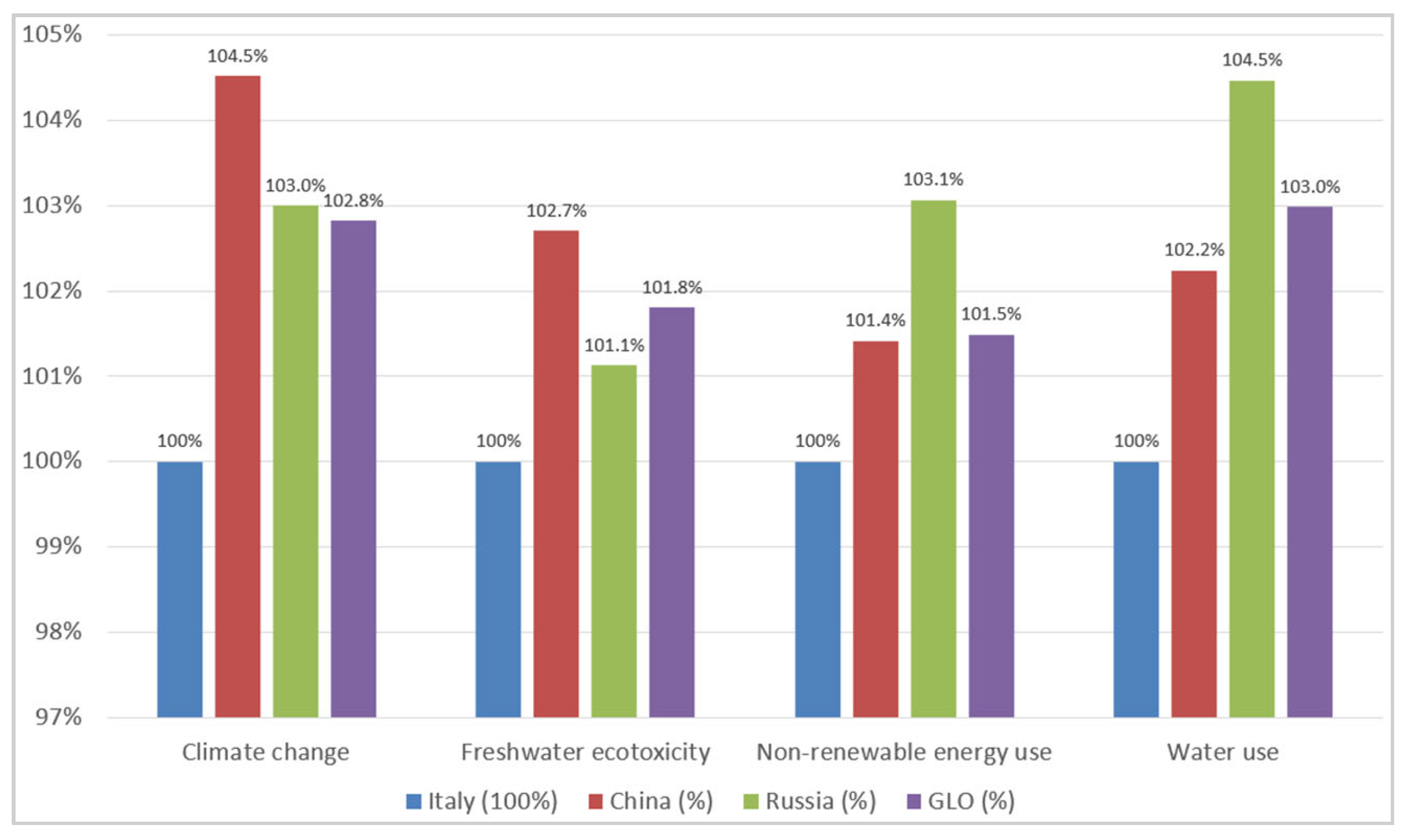
4.5. Geographical Sensitivity Analysis

The influence of geographical variability on the Life Cycle Assessment results was evaluated by comparing four geographical scenarios related to the production of the BFRC: Italy, China, Russia, and GLO (the latter representing the weighted global average provided by the Ecoinvent database). China and Russia were selected as geographical scenarios because they are among the main countries involved in the industrial production of basalt fibres, with representative and distinct energy mixes useful for assessing the influence of geographical context on environmental impacts.
The environmental impact results are fully reported in Table 9 for all considered impact categories. Figure 15 presents the results as percentage variations relative to the Italian scenario (baseline = 100%), focusing on four main categories: climate change, freshwater ecotoxicity, non-renewable energy use, and water use. Although differences emerge due to varying energy and production contexts, the overall trend remains consistent, with limited percentage variations across the analyzed geographical scenarios.
To provide a clearer and more detailed representation of the results related to the climate change impact category, Figure 16 presents a direct comparison between the impacts calculated for the four geographical scenarios of the BFRC and the reference value of the GFRC (indicated by the dashed line). This representation allows for a more immediate visualization of the significant reduction in climate impacts associated with the BFRC, ranging from 14% in the China scenario to 18% in the Italy scenario.
This result confirms that the BFRC represents a more environmentally sustainable alternative to the GFRC, even when accounting for geographical uncertainty in the datasets used.

5. Conclusions

In this study, the mechanical behaviour and sustainability of a basalt-fibre-reinforced composite (BFRC) and a glass-fibre-reinforced composite (GFRC) have been thoroughly investigated, highlighting the comparable mechanical properties of BFRCs and GFRCs, as obtained through static and stepwise fatigue tests. However, a significant difference emerges in their failure mechanisms.
  • Basalt fibres exhibit advantageous failure behaviour, offering extended operational lifespans and greater design flexibility.
  • The thermal and fatigue analyses further demonstrate the resilience of BFRCs under static and dynamic loads, reinforcing their suitability for demanding industrial applications.
  • The results of LCA emphasize the reduced environmental footprint of basalt fibres, including lower greenhouse gas emissions, resource depletion, and toxic substance releases.
These findings align with the increasing demand for eco-sustainable solutions in industries such as the automotive, aerospace, and construction industries. Although the higher cost of basalt fibres currently limits their adoption in cost-sensitive applications, advancements in production technologies are expected to enhance their economic feasibility. By integrating performance, sustainability, and cost-effectiveness, basalt fibre composites will be an alternative to traditional glass fibres, paving the way for innovative and environmentally responsible engineering solutions across many industrial sectors. Future challenges will involve comparisons with other types of composites, such as basalt and glass fibre composites obtained with polyester resin.

Author Contributions

Conceptualization, D.D., F.S., G.D.B., M.T. and G.R.; methodology, D.D., F.S., M.T. and G.R.; software, F.S. and M.T.; validation, D.D., F.S., G.D.B., M.T. and G.R.; formal analysis, D.D. and M.T.; investigation, D.D., F.S. and M.T.; resources, G.D.B.; data curation, D.D., F.S. and M.T.; writing—original draft preparation, D.D., F.S. and M.T.; writing—review and editing, D.D. and M.T.; visualization, D.D., F.S. and M.T.; supervision, G.D.B. and G.R. All authors have read and agreed to the published version of the manuscript.

Funding

This research received no external funding.

Data Availability Statement

Data is contained within the article. The data presented in this study are available on request from the corresponding author.

Conflicts of Interest

The authors declare no conflicts of interest.

References

  1. Vassilopoulos, A.P. The history of fiber-reinforced polymer composite laminate fatigue. Int. J. Fatigue 2020, 134, 105512. [Google Scholar] [CrossRef]
  2. Siengchin, S. A review on lightweight materials for defence applications: Present and future developments. Def. Technol. 2023, 24, 1–17. [Google Scholar] [CrossRef]
  3. Alshahrani, H.; Sebaey, T.A.; Awd Allah, M.M.; Abd El-baky, M.A. Jute-basalt reinforced epoxy hybrid composites for lightweight structural automotive applications. J. Compos. Mater. 2023, 57, 1315–1330. [Google Scholar] [CrossRef]
  4. Fiore, V.; Scalici, T.; Di Bella, G.; Valenza, A. A review on basalt fibre and its composites. Compos. B Eng. 2015, 74, 74–94. [Google Scholar] [CrossRef]
  5. Srikavi, A.; Mekala, M. Characterization of Sunn hemp fibers as a substitute for synthetic fibers in composites and various applications. Ind. Crops Prod. 2023, 192, 116135. [Google Scholar] [CrossRef]
  6. Anand, P.B.; Nagaraja, S.; Jayaram, N.; Sreenivasa, S.P.; Almakayeel, N.; Khan, T.M.Y.; Kumar, R.; Kumar, R.; Ammarullah, M.I. Kenaf fiber and hemp fiber multi-walled carbon nanotube filler-reinforced epoxy-based hybrid composites for biomedical applications: Morphological and mechanical characterization. J. Compos. Sci. 2023, 7, 324. [Google Scholar] [CrossRef]
  7. Malik, K.; Ahmad, F.; Yunus, N.A.; Gunister, E.; Ali, S.; Raza, A. Physical and mechanical properties of kenaf/flax hybrid composites. J. Appl. Polym. Sci. 2023, 140, e53421. [Google Scholar] [CrossRef]
  8. Ahmed, J.P.S.; Sudarsan, S.; Parthiban, E.; Trofimov, E.; Sridhar, B. Exploration of mechanical properties of hemp fiber/flax fiber reinforced composites based on biopolymer and epoxy resin. Mater. Today Proc. 2023; in press. [Google Scholar] [CrossRef]
  9. Zaragoza-Benzal, A.; Ferrández, D.; Prieto, M.I.; Atanes-Sánchez, E. Fire-resistant performance of new sustainable waste-lightened composites with glass and basalt fibres reinforcement. Constr. Build. Mater. 2024, 411, 134620. [Google Scholar] [CrossRef]
  10. Jagadeesh, P.; Rangappa, S.M.; Siengchin, S. Basalt fibers: An environmentally acceptable and sustainable green material for polymer composites. Constr. Build. Mater. 2024, 436, 136834. [Google Scholar] [CrossRef]
  11. Pavliukevich, Y.; Papko, L.; Trusova, E.; Uvarov, A. Optimization of the basalt glass composition for the continuous fiber production. Chem. Chem. Eng. 2024, 2022, 2. [Google Scholar] [CrossRef]
  12. Yorseng, K.; Mavinkere Rangappa, S.; Parameswaranpillai, J.; Siengchin, S. Towards green composites: Bioepoxy composites reinforced with bamboo/basalt/carbon fabrics. J. Clean. Prod. 2022, 363, 132314. [Google Scholar] [CrossRef]
  13. Pareek, K.; Saha, P.; Saha, P. Basalt Fiber and Its Composites: An Overview. In Proceedings of the National Conference on Advances in Structural Technologies (CoAST-2019), Assam, India, 1–3 February 2019; pp. 53–62. [Google Scholar]
  14. Nagaraju, S.B.; Priya, H.C.; Girijappa, Y.G.T.; Puttegowda, M. Lightweight and sustainable materials for aerospace applications. In Lightweight and Sustainable Composite Materials; Elsevier: Amsterdam, The Netherlands, 2023; pp. 157–178. [Google Scholar]
  15. Balaji, K.V.; Shirvanimoghaddam, K.; Rajan, G.S.; Ellis, A.V.; Naebe, M. Surface treatment of Basalt fiber for use in automotive composites. Mater. Today Chem. 2020, 17, 100334. [Google Scholar]
  16. Monaldo, E.; Nerilli, F.; Vairo, G. Basalt-based fiber-reinforced materials and structural applications in civil engineering. Compos. Struct. 2019, 214, 246–263. [Google Scholar] [CrossRef]
  17. Liu, H.; Yu, Y.; Liu, Y.; Zhang, M.; Li, L.; Ma, L.; Sun, Y.; Wang, W. A Review on Basalt Fiber Composites and Their Applications in Clean Energy Sector and Power Grids. Polymers 2022, 14, 2376. [Google Scholar] [CrossRef]
  18. Chowdhury, I.R.; Pemberton, R.; Summerscales, J. Developments and Industrial Applications of Basalt Fibre Reinforced Composite Materials. J. Compos. Sci. 2022, 6, 367. [Google Scholar] [CrossRef]
  19. Fiore, V.; Di Bella, G.; Valenza, A. Glass-basalt/epoxy hybrid composites for marine applications. Mater. Des. 2011, 32, 2091–2099. [Google Scholar] [CrossRef]
  20. Liu, J.; Chen, M.; Yang, J.; Wu, Z. Study on Mechanical Properties of Basalt Fibers Superior to E-glass Fibers. J. Nat. Fibers 2022, 19, 882–894. [Google Scholar] [CrossRef]
  21. Vashıshtha, A.; Sharma, D. Mechanical Performance of Basalt and Glass Woven Composites TT—Mechanical Performance of Basalt and Glass Woven Composites. Tekst. Ve Mühendis 2024, 31, 88–98. [Google Scholar] [CrossRef]
  22. Lopresto, V.; Leone, C.; De Iorio, I. Mechanical characterisation of basalt fibre reinforced plastic. Compos. B Eng. 2011, 42, 717–723. [Google Scholar] [CrossRef]
  23. Agrawal, M. A comparative study of static and fatigue performance of glass and basalt fiber reinforced epoxy composites. Polym. Compos. 2024, 45, 3551–3565. [Google Scholar] [CrossRef]
  24. Cucinotta, F.; Raffaele, M.; Salmeri, F. A Well-to-Wheel Comparative Life Cycle Assessment Between Full Electric and Traditional Petrol Engines in the European Context. In Advances on Mechanics, Design Engineering and Manufacturing III, Proceedings of the International Joint Conference on Mechanics, Design Engineering & Advanced Manufacturing, JCM 2020, Aix-en-Provence, France, 2–4 June 2020; Springer: Berlin/Heidelberg, Germany, 2021; pp. 188–193. [Google Scholar]
  25. Cucinotta, F.; Barberi, E.; Salmeri, F. A Review on Navigating Sustainable Naval Design: LCA and Innovations in Energy and Fuel Choices. J. Mar. Sci. Eng. 2024, 12, 520. [Google Scholar] [CrossRef]
  26. Keiser, D.; Schnoor, L.H.; Pupkes, B.; Freitag, M. Life cycle assessment in aviation: A systematic literature review of applications, methodological approaches and challenges. J. Air Transp. Manag. 2023, 110, 102418. [Google Scholar] [CrossRef]
  27. Curti, G.; La Rosa, G.; Orlando, M.; Risitano, A. Analisi tramite infrarosso termico della temperatura limite in prove di fatica. Proc. XIV Convegno Naz. AIAS 1986, 211–220. [Google Scholar]
  28. La Rosa, G.; Risitano, A. Thermographic methodology for rapid determination of the fatigue limit of materials and mechanical components. Int. J. Fatigue 2000, 22, 65–73. [Google Scholar] [CrossRef]
  29. Williams, P.; Liakat, M.; Khonsari, M.M.; Kabir, O.M. A thermographic method for remaining fatigue life prediction of welded joints. Mater. Des. 2013, 51, 916–923. [Google Scholar] [CrossRef]
  30. Colombo, C.; Vergani, L.; Burman, M. Static and fatigue characterisation of new basalt fibre reinforced composites. Compos. Struct. 2012, 94, 1165–1174. [Google Scholar] [CrossRef]
  31. Crisafulli, D.; Fintová, S.; Santonocito, D.; D’Andrea, D. Microstructural characterization and mechanical behaviour of laser powder Bed Fusion stainless steel 316L. Theor. Appl. Fract. Mech. 2024, 131, 104343. [Google Scholar] [CrossRef]
  32. Risitano, A.; Risitano, G. Determining fatigue limits with thermal analysis of static traction tests. Fatigue Fract. Eng. Mater. Struct. 2013, 36, 631–639. [Google Scholar] [CrossRef]
  33. Wernet, G.; Bauer, C.; Steubing, B.; Reinhard, J.; Moreno-Ruiz, E.; Weidema, B. The ecoinvent database version 3 (part I): Overview and methodology. Int. J. Life Cycle Assess. 2016, 21, 1218–1230. [Google Scholar] [CrossRef]
  34. ISO EN. 14044; Environmental Management, Life Cycle Assessment, Requirements and Guidelines. DIN Deutsches Institut für Normung e. V.: Berlin, Germany, 2006.
  35. Fořt, J.; Kočí, J.; Černý, R. Environmental efficiency aspects of basalt fibers reinforcement in concrete mixtures. Energies 2021, 14, 7736. [Google Scholar] [CrossRef]
  36. Ramachandran, K.; Gnanasagaran, C.L.; Vekariya, A. Life cycle assessment of carbon fiber and bio-fiber composites prepared via vacuum bagging technique. J. Manuf. Process 2023, 89, 124–131. [Google Scholar] [CrossRef]
  37. Scalici, T.; Pitarresi, G.; Badagliacco, D.; Fiore, V.; Valenza, A. Mechanical properties of basalt fiber reinforced composites manufactured with different vacuum assisted impregnation techniques. Compos. B Eng. 2016, 104, 35–43. [Google Scholar] [CrossRef]
  38. Talabari, A.A.; Alaei, M.H.; Shalian, H.R. Experimental Investigation of Tensile Properties in a Glass/Epoxy Sample Manufactured by Vacuum Infusion, Vacuum Bag and Hand Layup Process. J. Compos. Adv. Mater./Rev. Compos. Matériaux Avancés 2019, 29, 179–182. [Google Scholar] [CrossRef]
  39. Totaro, M.; Risitano, G.; Di Bella, G.; Crisafulli, D.; D’Andrea, D. A Comparative Study on Mechanical Properties and Failure Mechanisms in Basalt and Glass Fibre Reinforced Composites. Procedia Struct. Integr. 2024, 66, 205–211. [Google Scholar] [CrossRef]
  40. Fazio, S.; Biganzoli, F.; De Lv Zampori, L.; Sala, S.; Diaconu, E. Supporting Information to the Characterisation Factors of Recommended EF Life Cycle Impact Assessment Methods; Publications Office of the European Union: Luxembourg, 2018. [Google Scholar]
  41. World Health Organization. INFOSAN Activity Report 2018/2019; Food & Agriculture Org.: Rome, Italy, 2020. [Google Scholar]
Figure 1. Thermal phases during a static tensile test.
Jcs 09 00308 g001
Figure 2. (a) Vacuum infusion; (b) FRP laminate; (c) BRP laminate.
Jcs 09 00308 g002
Figure 3. (a) GF specimen; (b) BF specimen.
Jcs 09 00308 g003
Figure 4. Experimental test.
Jcs 09 00308 g004
Figure 5. (a) OpenLCA model graph of the basalt fibre composite specimen; (b) OpenLCA model graph of the glass fibre composite specimen.
Jcs 09 00308 g005
Figure 6. Energy related to the production process of 1 kg of composite material.
Jcs 09 00308 g006
Figure 7. Stress–strain curve for (a) the BFRC and (b) the GFRC.
Jcs 09 00308 g007
Figure 8. Temperature trend vs. applied stress (2 mm·min−1). (a) BFRC; (b) GFRB.
Jcs 09 00308 g008
Figure 9. Stepwise fatigue test R = 0.1 for (a) the BFRC and (b) the GFRC.
Jcs 09 00308 g009
Figure 10. Fatigue limit of (a) the BFRC and (b) the GFRC at R = 0.1 according to the TM.
Jcs 09 00308 g010
Figure 11. Matrix cracking in (a) the BFRC and (b) the GFRC. (c) BF segment failure; (d) BF delamination; (e) GF breaking.
Jcs 09 00308 g011
Figure 12. Broken specimens: (a) BF; (b) GF [39].
Jcs 09 00308 g012
Figure 13. Graphical comparison of the most significant environmental impact indicators for basalt and glass fibre samples.
Jcs 09 00308 g013
Figure 14. Percentage comparison of the BFRC versus GFRC across key environmental impact categories (GFRC = 100%).
Jcs 09 00308 g014
Figure 15. Percentage comparison of the BFRC’s environmental impacts relative to the Italian scenario (baseline = 100%) regarding four key categories.
Jcs 09 00308 g015
Figure 16. Direct comparison of climate change impacts of the BFRC in the four geographical scenarios relative to the GFRC value (dashed line).
Jcs 09 00308 g016
Table 1. Properties of vinyl ester resin (source: producer datasheet).
Product Specification upon Delivery
ViscositymPa × s130–170
Gel time (range 25–35 °C)min65–75
Curing time (range 25–peak)min89–95
Properties of Cast Unfilled Resin
HardnessBarcol40
Tensile strengthMPa78
Tensile modulusGPa3
Elongation at break%3.4
Flexural strengthMPa150
Flexural modulusGPa3.5
Heat deflection temperature°C107
Impact resistance (unnotched sample)kJ/m215
Table 2. Properties of glass and basalt fibres (source: producer datasheet).
BasaltGlass
Tensile modulus [GPa]8976
Density [g/cm3]2.031.89
Table 3. Number of tests.
BasaltGlass
Static tensile tests55
Stepwise fatigue tests22
Table 4. Material and energy inputs required to produce 1 kg of basalt fibres.
InputQuantity
Water0.748 kg
Basalt rock1.4 kg
Lubricating oil0.0021 kg
Silicone0.004 kg
Electricity1.2 kWh
Natral gas12.5 Mj
Diesel0.0124 L
Table 5. Results from experimental static tensile tests.
BFRCGFRCPercentage Increase (%)
Ultimate tensile strength (Mpa)374 ± 20.2295 ± 4.7+26.7%
Table 6. Results from energy methods.
BFRCGFRC
Stress Limit performed with STM (MPa)99.9 ± 6.45101.7 ± 5.24
Fatigue Limit performed with RTM (MPa)96.5 ± 0.2 104.8 ± 0.8
Table 7. Life Cycle Impact Assessment results for the basalt fibre specimen.
Impact CategoryResultsUnit
Acidification2.75 × 10−3mol H+-Eq
Climate change6.67 × 10−1kg CO2-Eq
Climate change: biogenic2.29 × 10−3kg CO2-Eq
Climate change: fossil6.64 × 10−1kg CO2-Eq
Climate change: land use and land use change1.77 × 10−4kg CO2-Eq
Ecotoxicity: freshwater4.89 × 100CTUe
Ecotoxicity: freshwater, inorganics2.52 × 100CTUe
Ecotoxicity: freshwater, organics2.37 × 100CTUe
Energy resources: non-renewable1.12 × 101MJ, net calorific value
Eutrophication: freshwater1.45 × 10−4kg P-Eq
Eutrophication: marine4.36 × 10−4kg N-Eq
Eutrophication: terrestrial4.71 × 10−3mol N-Eq
Human toxicity: carcinogenic3.49 × 10−9CTUh
Human toxicity: carcinogenic, inorganics8.54 × 10−11CTUh
Human toxicity: carcinogenic, organics3.40 × 10−9CTUh
Human toxicity: non-carcinogenic7.79 × 10−9CTUh
Human toxicity: non-carcinogenic, inorganics7.29 × 10−9CTUh
Human toxicity: non-carcinogenic, organics4.96 × 10−10CTUh
Ionizing radiation: human health6.57 × 10−2kBq U235-Eq
Land use3.50 × 100dimensionless
Material resources: metals/minerals7.47 × 10−6kg Sb-Eq
Ozone depletion2.32 × 10−8kg CFC-11-Eq
Particulate matter formation1.71 × 10−8disease incidence
Photochemical oxidant formation: human health2.02 × 10−3kg NMVOC-Eq
Water use3.23 × 10−1m3 world Eq deprived
Table 8. Life Cycle Impact Assessment results for the glass fibre specimen.
Impact CategoryResultsUnit
Acidification3.75 × 10−3mol H+-Eq
Climate change8.12 × 10−1kg CO2-Eq
Climate change: biogenic2.31 × 10−3kg CO2-Eq
Climate change: fossil8.09 × 10−1kg CO2-Eq
Climate change: land use and land use change2.96 × 10−4kg CO2-Eq
Ecotoxicity: freshwater6.89 × 100CTUe
Ecotoxicity: freshwater, inorganics3.50 × 100CTUe
Ecotoxicity: freshwater, organics3.39 × 100CTUe
Energy resources: non-renewable1.35 × 101MJ, net calorific value
Eutrophication: freshwater1.89 × 10−4kg P-Eq
Eutrophication: marine6.31 × 10−4kg N-Eq
Eutrophication: terrestrial6.71 × 10−3mol N-Eq
Human toxicity: carcinogenic4.90 × 10−9CTUh
Human toxicity: carcinogenic, inorganics1.56 × 10−10CTUh
Human toxicity: carcinogenic, organics4.75 × 10−9CTUh
Human toxicity: non-carcinogenic1.36 × 10−8CTUh
Human toxicity: non-carcinogenic, inorganics1.30 × 10−8CTUh
Human toxicity: non-carcinogenic, organics6.30 × 10−10CTUh
Ionizing radiation: human health7.89 × 10−2kBq U235-Eq
Land use3.90 × 100dimensionless
Material resources: metals/minerals1.92 × 10−5kg Sb-Eq
Ozone depletion1.85 × 10−8kg CFC-11-Eq
Particulate matter formation2.56 × 10−8disease incidence
Photochemical oxidant formation: human health2.78 × 10−3kg NMVOC-Eq
Water use3.91 × 10−1m3 world Eq deprived
Table 9. Environmental impact results of the BFRC in different geographical scenarios across all considered categories.
Impact CategoryItalyChinaRussiaGloUnit
Acidification2.75 × 10−32.90 × 10−32.80 × 10−32.82 × 10⁻³mol H+-Eq
Climate change6.67 × 10−16.97 × 10−16.87 × 10−16.85 × 10⁻¹kg CO2-Eq
Climate change: biogenic2.29 × 10−32.03 × 10−32.04 × 10−32.05 × 10⁻³kg CO2-Eq
Climate change: fossil6.64 × 10−16.95 × 10−16.84 × 10−16.83 × 10⁻¹kg CO2-Eq
Climate change: land use and land use change1.77 × 10−41.92 × 10−43.00 × 10−42.24 × 10⁻⁴kg CO2-Eq
Ecotoxicity: freshwater4.89 × 1005.02 × 1004.94 × 1004.98 × 100CTUe
Ecotoxicity: freshwater, inorganics2.52 × 1002.62 × 1002.54 × 1002.58 × 100CTUe
Ecotoxicity: freshwater, organics2.37 × 1002.40 × 1002.40 × 1002.40 × 100CTUe
Energy resources: non-renewable1.12 × 1011.14 × 1011.16 × 1011.14 × 101MJ, net calorific value
Eutrophication: freshwater1.45 × 10−41.49 × 10−41.60 × 10−41.56 × 10⁻⁴kg P-Eq
Eutrophication: marine4.36 × 10−44.75 × 10−44.49 × 10−44.57 × 10⁻⁴kg N-Eq
Eutrophication: terrestrial4.71 × 10−35.07 × 10−34.76 × 10−34.86 × 10⁻³mol N-Eq
Human toxicity: carcinogenic3.49 × 10−93.59 × 10−93.61 × 10−93.59 × 10⁻⁹CTUh
Human toxicity: carcinogenic, inorganics8.54 × 10−118.63 × 10−118.60 × 10−118.63 × 10⁻¹¹CTUh
Human toxicity: carcinogenic, organics3.40 × 10−93.50 × 10−93.52 × 10−93.50 × 10⁻⁹CTUh
Human toxicity: non-carcinogenic7.79 × 10−98.07 × 10−97.98 × 10−98.03 × 10⁻⁹CTUh
Human toxicity: non-carcinogenic, inorganics7.29 × 10−97.55 × 10−97.47 × 10−97.52 × 10⁻⁹CTUh
Human toxicity: non-carcinogenic, organics4.96 × 10−105.13 × 10−105.08 × 10−105.08 × 10⁻¹⁰CTUh
Ionizing radiation: human health6.57 × 10−26.49 × 10−27.43 × 10−26.77 × 10⁻²kBq U235-Eq
Land use3.50 × 1003.48 × 1003.40 × 1003.46 × 100dimensionless
Material resources: metals/minerals7.47 × 10−67.66 × 10−67.66 × 10−67.66 × 10⁻⁶kg Sb-Eq
Ozone depletion2.32 × 10−81.56 × 10−81.67 × 10−81.58 × 10⁻⁸kg CFC-11-Eq
Particulate matter formation1.71 × 10−82.02 × 10−81.72 × 10−81.83 × 10⁻⁸disease incidence
Photochemical oxidant formation: human health2.02 × 10−32.17 × 10−32.12 × 10−32.13 × 10⁻³kg NMVOC-Eq
Water use3.23 × 10−13.31 × 10−13.38 × 10−13.33 × 10⁻¹m3 world Eq deprived
Disclaimer/Publisher’s Note: The statements, opinions and data contained in all publications are solely those of the individual author(s) and contributor(s) and not of MDPI and/or the editor(s). MDPI and/or the editor(s) disclaim responsibility for any injury to people or property resulting from any ideas, methods, instructions or products referred to in the content.

